
Chapter 19: Drawing Curves
So far in this book, you’ve been using basic lines, arcs, and circles to create your drawings. Now it’s time to add polylines and spline curves to your repertoire. Polylines offer many options for creating forms, including solid fills and free-form curved lines. Spline curves are perfect for drawing accurate and smooth nonlinear objects.
In this chapter, you’ll learn to do the following:
- Create and edit polylines
- Create a polyline spline curve
- Create and edit true spline curves
- Mark divisions on curves
Polylines are like composite line segments and arcs. A polyline may look like a series of line segments, but it acts like a single object. This characteristic makes polylines useful for a variety of applications, as you’ll see in the upcoming exercises.
Drawing a Polyline
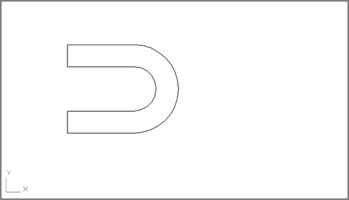
First, to learn about the polyline, you’ll begin a drawing of the top view of the joint shown in Figure 19-1.
Figure 19-1: A sketch of a metal joint

Follow these steps to draw the joint:
1. Open a new file using the acad.dwt template, and save it as Joint2d. Don’t bother to make special setting changes because you’ll create this drawing with the default settings.
2. From the navigation bar, choose Zoom All from the flyout or type Z↵A↵.
3. Click the Polyline tool on the Draw panel, or type Pl↵.
4. At the Specify start point: prompt, enter a point at coordinate 3,3 to start your polyline.
5. At the Specify next point or [Arc/Halfwidth/Length/Undo/Width]: prompt, enter @3<0↵ to draw a horizontal line of the joint.
6. At the Specify next point or [Arc/Close/Halfwidth/Length/Undo/Width]: prompt, enter A↵ to continue your polyline with an arc.
Using the Arc Option in the Polyline Tool
The Arc option enables you to draw an arc that starts from the last point you selected and then select additional options. Select the Arc option; as you move your cursor, an arc follows it in a tangential direction from the first line segment you drew. You can return to drawing line segments by entering L↵.
7. At the prompt
Specify endpoint of arc or
[Angle/CEnter/CLose/Direction/Halfwidth/Line/Radius/Second pt/Undo/Width]:
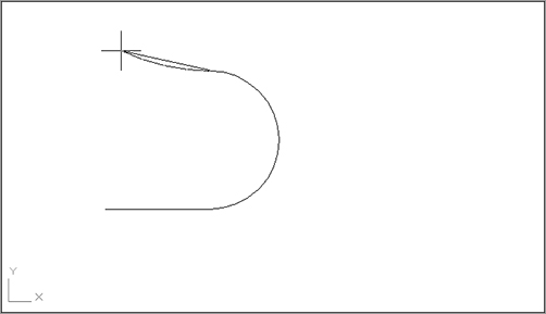
enter @4<90↵ to draw a 180° arc from the last point you entered. Your drawing should now look similar to Figure 19-2.
8. To continue the polyline with another line segment, enter L↵.
Figure 19-2: A polyline line and arc
9. At the Specify next point or [Arc/Close/Halfwidth/Length/Undo/Width]: prompt, enter @3<180↵. Another line segment continues from the end of the arc.
10. Press ↵ to exit the Polyline tool.
You now have a sideways, U-shaped polyline that you’ll use in the next exercise to complete the top view of your joint.
Setting Polyline Options
Let’s take a break from the tutorial to look at some of the options in the Polyline prompt that you didn’t use:
Close Draws a line segment from the last endpoint of a sequence of lines to the first point picked in that sequence. This works exactly like the Close option for the Line command.
Length Enables you to specify the length of a line that will be drawn at the same angle as the last line entered.
Halfwidth Creates a tapered line segment or an arc by specifying half its beginning and ending widths (see Figure 19-3).
Figure 19-3: A tapered line segment and an arc created with Halfwidth
Width Creates a tapered line segment or an arc by specifying the full width of the segment’s beginning and ending points.
Undo Deletes the last line segment drawn.
Radius/Second pt The Radius and Second pt options appear when you use the arc option to draw polyline segments. Radius lets you specify a radius for the arc and Second pt lets you specify a second point in a three-point arc.
If you want to break a polyline into simple lines and arcs, you can use the Explode option on the Modify panel, just as you would with blocks. After a polyline is exploded, it becomes a set of individual line segments or arcs.
To turn off the filling of solid polylines, open the Options dialog box and click the Display tab. Clear the Apply Solid Fill check box in the Display Performance group.
Filleting a Polyline
You can use the Fillet tool on the Modify panel to fillet all the vertices of a polyline composed of straight-line segments. Click the Fillet tool, set your fillet radius by typing R↵ and entering a radius value, type P↵ to select the Polyline option, and then pick the polyline you want to fillet.
You can edit polylines with many of the standard editing commands. To change the properties of a polyline, click the polyline to select it, right-click, and select Properties to open the Properties palette. You can use the Stretch command on the Modify panel to move vertices of a polyline. The Trim, Extend, and Break commands on the Modify panel also work with polylines.
In addition, many editing capabilities are offered only for polylines. For instance, later in this section you’ll see how to smooth out a polyline by using the Fit option in the Pedit command.
In this exercise, you’ll use the Offset command on the Modify panel to add the inside portion of the joint:
1. Click the Offset tool in the Home tab’s Modify panel, or type O↵.
2. At the Specify offset distance or [Through/Erase/Layer] <Through>: prompt, enter 1.
3. At the Select object to offset or [Exit/Undo]<Exit>: prompt, pick the U-shaped polyline you just drew.
4. At the Specify point on side to offset or [Exit/Multiple/Undo] <Exit>: prompt, pick a point on the inside of the U shape. You’ll see a concentric copy of the polyline appear (see Figure 19-4).
5. Press ↵ to exit the Offset command.
The concentric copy of a polyline made by choosing the Offset tool can be useful when you need to draw complex parallel curves like the ones in Figure 19-5.
Next, complete the top view of the joint. To do this, you’ll use the Edit Polyline tool, otherwise known as the Pedit command:
1. Connect the ends of the polylines with two short line segments (see Figure 19-6).
2. Choose Edit Polyline from the expanded Modify panel or type PE↵.
3. At the Select polyline or [Multiple]: prompt, pick the outermost polyline.
Figure 19-4: The offset polyline
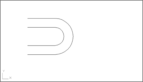
Figure 19-5: Sample complex curves drawn by using offset polylines
Figure 19-6: The polyline so far
4. At the prompt
Enter an option
[Close/Join/Width/Edit vertex/Fit/Spline/Decurve/Ltype gen/Reverse/Undo]:
enter J↵ for the Join option.
5. At the Select objects: prompt, select all the objects you’ve drawn so far.
6. Press ↵ to join all the objects into one polyline. It appears that nothing has happened.
7. Press ↵ again to exit the Pedit command.
8. Click the drawing to expose its grips. The entire object is highlighted, indicating that all the lines have been joined into a single polyline.
What to Do If the Join Option Doesn’t Work
If the objects to be joined don’t touch, you can use the fuzz join feature. Type Pe↵M↵ to start the Pedit command with the Multiple option, then select all the objects you want to join and press ↵. If you see a convert message, enter Y↵. At the Enter an option [Close/Open/Join/Width/Fit/Spline/Decurve/Ltype gen/Undo]: prompt, enter J↵. At the Enter fuzz distance or [Jointype]: prompt, enter a distance that approximates the size of the gap between objects. By default, AutoCAD extends the lines so they join end to end. You can use the Jointype option if you want Pedit to join segments with an additional segment.
By using the Width option under Edit Polyline, you can change the width of a polyline. Let’s change the width of your polyline to give some width to the outline of the joint. To do this, you’ll use the Edit Polyline tool again, but this time you’ll use a shortcut:
1. Double-click the polyline.
2. At the Enter an option [Open/Join/Width/Edit vertex/Fit/Spline/Decurve/Ltype gen/Reverse/Undo]: prompt, enter W↵ for the Width option.
3. At the Specify new width for all segments: prompt, enter .03↵ for the new width of the polyline. The line changes to the new width (see Figure 19-7), and you now have a top view of your joint.
4. Press ↵ to exit the Pedit command.
5. Save this file.
In most cases, you can simply double-click on a polyline to start the Pedit command. But if you want to edit multiple polylines or if you want to convert an object or set of objects into a polyline, use the Edit Polyline tool from the Modify panel to start Pedit.
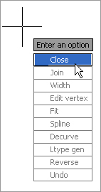
In addition, if you have Dynamic Input turned on in the status bar, you can select the Edit Polyline options from a menu that appears at the cursor (Figure 19-8).
Figure 19-7: The polyline with a new thickness
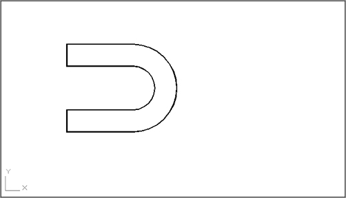
Figure 19-8: The Edit Polyline options that appear at the cursor
Setting Pedit Options
Here’s a brief look at a few of the Pedit options you didn’t try firsthand:
Close Connects the two endpoints of a polyline with a line segment. If the polyline you selected to be edited is already closed, this option changes to Open.
Open Removes the last segment added to a closed polyline.
Spline/Decurve The Spline option smoothes a polyline into a spline curve (discussed in detail later in this chapter). The Decurve option changes a spline polyline back into its original shape before the Spline option was applied.
Edit Vertex Lets you edit each vertex of a polyline individually (discussed in detail later in this section).
Fit Turns polyline segments into a series of arcs.
Ltype Gen Controls the way noncontinuous linetypes pass through the vertices of a polyline. If you have a fitted or spline curve with a noncontinuous linetype, turn on this option.
Reverse Reverses the orientation of a polyline. The orientation is based on the order in which points are selected to create the polyline. The first point picked is the beginning, or point 1; the next point is point 2, and so on. In some cases, you may want to reverse this order using the Reverse option.
Undo Removes the last polyline line segment.
Using Polylines to Set Line Weights
Typically, you would use the Lineweight feature of AutoCAD to set line weights in your drawing. In cases where the Lineweight feature will not work, you can change the thickness of regular lines and arcs by using Pedit to change them into polylines and then using the Width option to change their width.
Smoothing Polylines
You can create a curve in AutoCAD in many ways. If you don’t need the representation of a curve to be accurate, you can use a polyline curve. In the following exercise, you’ll draw a polyline curve to represent a contour on a topographical map:
1. Open the topo.dwg file. The top image in Figure 19-9 contains the drawing of survey data. Some of the contours have already been drawn in between the data points.
2. Zoom in to the upper-right corner of the drawing so your screen displays the area shown in the bottom image in Figure 19-9.
3. Click the Polyline tool on the Draw panel. Using the Center osnap, draw a polyline that connects the points labeled 254.00. Your drawing should look like the bottom image in Figure 19-9.
4. Press ↵.
5. Next you’ll convert the polyline you just drew into a smooth contour line. Double-click the contour line you just drew.
6. At the prompt
Enter an option
[Close/Join/Width/Edit vertex/Fit/Spline/Decurve/Ltype gen/Reverse/Undo]:
type F↵ to select the Fit option. The polyline smoothes out into a series of connected arcs that pass through the data points.
7. Press ↵ to end the command.
Your contour is now complete. The Fit option under the Pedit command causes AutoCAD to convert the straight-line segments of the polyline into arcs. The endpoints of the arcs pass through the endpoints of the line segments, and the curve of each arc depends on the direction of the adjacent arc. This gives the effect of a smooth curve. Next you’ll use this polyline curve to experiment with some of the editing options unique to the Pedit command.
Editing Vertices
One of the Pedit options that I haven’t yet discussed, Edit Vertex, is like a command within a command. Edit Vertex has numerous suboptions that enable you to fine-tune your polyline by giving you control over individual vertices.
Figure 19-9: The topo.dwg file shows survey data portrayed in an AutoCAD drawing. Notice the dots indicating where elevations were taken. The actual elevation value is shown with a diagonal line from the point.
To access the Edit Vertex options, follow these steps:
1. Turn off the Data and Border layers to hide the data points and border.
2. Double-click the polyline you just drew.
3. Type E↵ to enter Edit Vertex mode. An X appears at the beginning of the polyline, indicating the vertex that will be affected by the Edit Vertex options.
When using Edit Vertex, you must be careful about selecting the correct vertex to be edited. Edit Vertex has 10 options. You often have to exit the Edit Vertex operation and use Pedit’s Fit option to see the effect of several Edit Vertex options on a curved polyline.
Edit Vertex Suboptions
After you enter the Edit Vertex mode of the Pedit command, you can perform the following functions:
- Break the polyline between two vertices.
- Insert a new vertex.
- Move an existing vertex.
- Regen the drawing to view the current shape of the polyline.
- Straighten a polyline between two vertices.
- Change the tangential direction of a vertex.
- Change the width of the polyline at a vertex.
Turning Objects into Polylines and Polylines into Splines
At times, you’ll want to convert regular lines, arcs, or even circles into polylines. You might want to change the width of lines or join lines to form a single object such as a boundary. Here are the steps to convert lines, arcs, and circles into polylines:
1. Click the Edit Polyline tool from the Home tab’s expanded Modify panel, or type Pe↵ at the Command prompt.
2. At the Select polyline or [Multiple]: prompt, pick the object you want to convert. If you want to convert a circle to a polyline, first break the circle (using the Break tool on the Modify panel) so it becomes an arc of approximately 359°.
3. At the prompt
Object selected is not a polyline. Do you want to turn it into one? <Y>:
press ↵. The object is converted into a polyline.
If you want to convert several objects to polylines, type M↵ at the Select polyline or [Multiple]: prompt, then select the objects you want to convert. You will see the Convert Lines, Arcs and Splines to polylines [Yes/No]? <Y>: prompt. Type Y↵, and all the selected objects are converted to polylines. You can then go on to use other Pedit options on the selected objects.
To turn a polyline into a true spline curve, do the following:
1. Click the Edit Polyline tool from the Home tab’s expanded Modify panel, or type Pe↵. Select the polyline you want to convert.
2. Type S↵ to turn it into a polyline spline, then press ↵ to exit the Pedit command.
3. Click the Spline tool on the Home tab’s expanded Draw panel or type Spl↵.
4. At the Specify first point or [Method/Knots/Object]: prompt, type O↵ for the Object option.
5. At the Select spline-fit polyline: prompt, click the polyline spline. Although it may not be apparent at first, the polyline is converted into a true spline.
You can also use the Edit Spline tool on the Home tab’s expanded Modify panel (or enter Spe↵) to edit a polyline spline. If you do, the polyline spline is automatically converted into a true spline.
If you know you’ll always want to convert an object into a polyline when using Pedit, you can turn on the Peditaccept system variable. Enter peditaccept↵ at the Command prompt, and then enter 1↵.
These functions are presented in the form of the following prompt:
[Next/Previous/Break/Insert/Move/Regen/Straighten/Tangent/Width/eXit] <N>:
The following sections examine each of the options in this prompt, starting with Next and Previous.
The Next and Previous Options
The Next and Previous options let you select a vertex for editing. When you start the Edit Vertex option, an X appears on the selected polyline to designate its beginning. As you select Next or Previous, the X moves from vertex to vertex to show which one is being edited. Let’s try this:
1. Press ↵ a couple of times to move the X along the polyline. (Because Next is the default option, you only need to press ↵ to move the X.)
2. Type P↵ for Previous. The X moves in the opposite direction. The default option becomes P.
Why Reverse a Polyline
One of more frequently asked questions I receive from readers is “How can I reverse the direction of a polyline?” It may seem like an odd question to someone new to AutoCAD, but reversing a polyline has quite a few uses. Perhaps the most common use is to turn a polyline that uses a complex linetype, one that includes text, right side up so that the text can be read more easily. (See Chapter 28 for an example of a linetype that includes text.) If for some reason you need to reverse the direction of a polyline or spline, you can do so by using the Reverse option in the Pedit command.
The Break Option
The Break option breaks the polyline between two vertices:
1. Position the X on one end of the segment you want to break.
2. Enter B↵ at the Command prompt.
3. At the Enter an option [Next/Previous/Go/eXit] <N>: prompt, use Next or Previous to move the X to the other end of the segment to be broken.
4. When the X is in the proper position, enter G↵ to break the polyline (see Figure 19-10).
You can also use the Break and Trim options on the Modify panel to break a polyline anywhere, as you did when you drew the toilet seat in Chapter 3.
The Insert Option
Next, try the Insert option, which inserts a new vertex:
1. Type X↵ to exit the Edit Vertex option temporarily. Then type U↵ to undo the break.
2. Type E↵ to return to the Edit Vertex option.
3. Press ↵ to advance the X marker to the next point.
4. Enter I↵ to select the Insert option.
5. When the prompt Specify location for new vertex: appears, along with a rubber-banding line originating from the current X position (see Figure 19-11), pick a point indicating the new vertex location. The polyline is redrawn with the new vertex.
Figure 19-10: How the Break option works
Figure 19-11: The new vertex location
Notice that the inserted vertex appears between the currently marked vertex and the next vertex, so the Insert option is sensitive to the direction of the polyline. If the polyline is curved, the new vertex won’t immediately be shown as curved. (See the first image in Figure 19-12.) You must smooth it out by exiting the Edit Vertex option and then using the Fit option, as you did to edit the site plan. (See the second image in Figure 19-12.) You can also use the Stretch command (on the Modify panel) to move a polyline vertex.
The Move Option
In this brief exercise, you’ll use the Move option to move a vertex:
1. Undo the inserted vertex by exiting the Edit Vertex option (enter X↵) and typing U↵.
2. Restart the Edit Vertex option, and use the Next or Previous option to place the X on the vertex you want to move.
3. Enter M↵ for the Move option.
4. When the Specify new location for marked vertex: prompt appears, along with a rubber-banding line originating from the X (see the first image in Figure 19-13), pick the new vertex. The polyline is redrawn (see the second image in Figure 19-13). Again, if the line is curved, the new vertex appears as a sharp angle until you use the Fit option (see the final image in Figure 19-13).
Figure 19-12: The polyline before and after the curve is fitted

You can also move a polyline vertex by using its grip.
The Regen Option
In some cases, the effect of an option does not appear in the drawing immediately. You can use the Regen option to update the display of the polyline and see any changes you’ve made up to that point.
Figure 19-13: Picking a new location for a vertex with the polyline before and after the curve is fitted
The Straighten Option
The Straighten option straightens all the vertices between two selected vertices. Using the Straighten option is a quick way to delete vertices from a polyline, as shown in the following exercise:
1. Undo the moved vertex (from the previous exercise).
2. Start the Edit Vertex option again, and select the starting vertex for the straight line.
3. Enter S↵ for the Straighten option.
4. At the Enter an option [Next/Previous/Go/eXit] <N>: prompt, move the X to the location for the other end of the straight-line segment.
5. After the X is in the proper position, enter G↵ for the Go option. The polyline straightens between the two selected vertices (see Figure 19-14).
Figure 19-14: A polyline after straightening
The Tangent Option
The Tangent option alters the direction of a curve on a curve-fitted polyline:
1. Undo the straightened segment from the previous exercise.
2. Restart the Edit Vertex option, and position the X on the vertex you want to alter.
3. Enter T↵ for the Tangent option. A rubber-banding line appears. (See the top image in Figure 19-15.)
4. Point the rubber-banding line in the direction of the new tangent, and click the mouse. An arrow appears, indicating the new tangent direction. (See the second image in Figure 19-15.)
Don’t worry if the polyline shape doesn’t change. You must use Fit to see the effect of Tangent. (See the final image in Figure 19-15.)
The Width Option
Finally, you’ll try the Width option. Unlike the Pedit command’s Width option, the Edit Vertex/Width option enables you to alter the width of the polyline at any vertex. Thus you can taper or otherwise vary polyline thicknesses. Try these steps:
1. Undo the tangent arc from the previous exercise.
2. Return to the Edit Vertex option, and place the X at the beginning vertex of a polyline segment you want to change.
3. Type W↵ to issue the Width option.
4. At the Specify starting width for next segment <0.0000>: prompt, enter a value—12↵, for example—indicating the polyline width desired at this vertex.
5. At the Specify ending width for next segment <12.0000>: prompt, enter the width—24↵, for example—for the next vertex.
The width of the polyline changes to your specifications (see Figure 19-16).
Figure 19-15: Picking a new tangent direction

The Width option is useful when you want to create an irregular or curved area in your drawing that is to be filled in solid. This is another option that is sensitive to the polyline direction.
Figure 19-16: A polyline with the width of one segment increased

As you’ve seen throughout these exercises, you can use the Undo option to reverse the last Edit Vertex option used. You can also use the Exit option to leave Edit Vertex at any time. Enter X↵ to display the Pedit prompt:
Enter an option
[Close/Join/Width/Edit vertex/Fit/Spline/Decurve/Ltype gen/Reverse/Undo]:
Filling In Solid Areas
You’ve learned how to create a solid area by increasing the width of a polyline segment. But suppose you want to create a solid shape or a thick line. AutoCAD provides the Solid, Trace, and Donut commands to help you draw simple filled areas. The Trace command acts just like the Line command (with the added feature of allowing you to draw wide line segments). Solid lets you create solid filled areas with straight sides, and Donut draws circles with a solid width.
You can create free-form, solid-filled areas by using the Solid hatch pattern. Create an enclosed area by using any set of objects, and then use the Hatch tool to apply a solid hatch pattern to the area. See Chapter 7 for details on using the Hatch tool.
Creating a Polyline Spline Curve
The Pedit command’s Spline option (named after the spline tool used in manual drafting) offers you a way to draw smoother and more controllable curves than those produced by the Fit option. A polyline spline doesn’t pass through the vertex points as a fitted curve does. Instead, the vertex points act as weights pulling the curve in their direction. These “weighted” vertex points are called control vertices. The polyline spline touches only its beginning and end vertices. Figure 19-17 illustrates this concept.
A polyline spline curve doesn’t represent a mathematically true curve. See the next section, “Using True Spline Curves,” to learn how to draw a more accurate spline curve.
Figure 19-17: The polyline spline curve pulled toward its control vertices
Let’s see how using a polyline spline curve may influence the way you edit a curve:
1. Undo the width changes you made in the previous exercise.
2. To change the contour into a polyline spline curve, double-click the polyline to be curved.
3. At the Enter an option [Close/Join/Width/Edit vertex/Fit/Spline/Decurve/Ltype gen/Reverse/Undo]: prompt, enter S↵. Your curve changes to look like Figure 19-18.
4. Press ↵ to exit Edit Polyline.
Figure 19-18: A spline curve
The curve takes on a smoother, more graceful appearance. It no longer passes through the points you used to define it. To see where the points went and to find out how spline curves act, do the following:
1. Click the curve. The original vertices appear as grips. (See the first image in Figure 19-19.)
2. Click the grip that is second from the top of the curve, as shown in the first image in Figure 19-19, and move the grip around. The curve follows your moves, giving you immediate feedback on how it will look.
3. Pick a point as shown in the second image in Figure 19-19. The curve is now fixed in its new position, as shown in the bottom image of Figure 19-19.
Figure 19-19: The fitted curve changed to a spline curve, with the location of the second vertex and the new curve

Displaying the Curve Frame
You can set up AutoCAD to display both the curved and the straight segments defining the curve by turning on the Splframe system variable. Enter splframe↵1↵, and then issue a Regen command. You’ll see a frame that connects the grips of the curve. To turn off the display of the straight segments, enter splframe↵0↵.
So far, you’ve been working with polylines to generate spline curves. The advantage of using polylines for curves is that they can be enhanced in many ways. You can modify their width, for instance, or join several curves. But at times, you’ll need a more exact representation of a curve.
The spline object, created by choosing the Spline tool in the Home tab’s expanded Draw panel, produces a more accurate model of a spline curve in addition to giving you more control over its shape.
The spline objects are true Non-Uniform Rational B-Spline (NURBS) curves. A full description of NURBS is beyond the scope of this book, but basically, NURBS are standard mathematical forms used to represent shapes.
Drawing a True Spline
The following steps describe the process used to create a spline curve. You don’t have to create them now. Make a note of this section, and refer to it when you need to draw and edit a spline. Here are the steps:
1. Choose the Spline tool from the expanded Draw panel, or type Spl↵.
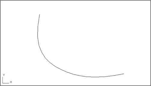
2. At the Specify first point or [Method/Knots/Object]: prompt, select a point to start the curve. (See Figure 19-20.) The prompt changes to Enter next point or [start Tangency/toLerance]:.
3. Continue to select points until you’ve entered all the points you need. As you pick points, a curve appears, and it bends and flows as you move your cursor. In Figure 19-20, a Center object snap was used to select the donuts that appear as dots in the survey plan.
4. After you’ve selected the last point, press ↵ to exit the Spline command.
If you prefer, you can also control the tangency of the spline at its first and last points. The following steps describe how the Tangency option can be used:
1. Start the spline just as before, and select the start point. At the Enter next point or [start Tangency/toLerance]: prompt, type T↵.
2. The prompt changes to Specify start tangent:. Also, a rubber-banding line appears from the first point of the curve to the cursor. Select a point indicating the tangency of the first point.
3. Continue to select the other points of your spline. After you’ve selected the last point, type T↵.
4. Use the cursor to indicate the tangency of the spline at the last point.
Figure 19-20: Start the spline curve at the first data point and then continue to select points.
You now have a smooth curve that passes through the points you selected. These points are called the fit points. If you click the curve, you’ll see the grips appear at the location of these fit points, and you can adjust the curve by clicking the grip points and moving them. You’ll also see an arrowhead grip that appears at the beginning of the spline. If you click this arrowhead grip, you see two options: Show Fit Points and Show Control Vertices (Figure 19-21).
Figure 19-21: The Show Fit Points and Show Control Vertices options.
The Show Fit Points option will display the grips at the fit points, which are the points you used to draw the spline in the previous example. By default, these fit points lie on the spline, though you can adjust how close the spline follows the fit points. You can also view the control vertices, or CVs for short, which are points that control the curvature of the spline and do not lie on the spline itself (see Figure 19-17). Along with the control vertices, you see a set of vectors called the control polyline. The control polyline helps you visualize the relationship between the CVs and the spline.
Understanding the Spline Options
You may have noticed a few other options in the first Spline command prompt. When you start the Spline command, you see the Method, Knots, Degree, and Object options:
Method Method lets you choose between Fit and CV. The Fit option causes the spline to be drawn through the lines you select. The CV, or Control Vertices, option causes the spline to use your selected points as control vertices (see Figure 19-17). Once you’ve drawn a spline, you can switch between fit and CV views of your polyline (Figure 19-21).
Knots This option is available only if Fit is chosen in the Method option discussed previously. This option offers three additional options: Chord, Square Root, and Uniform, which affect the shape of the spline as it passes through the fit point.
Chord The Chord option numbers the knots with decimal values.
Square Root The Square Root option numbers them based on the square root of the chord length between consecutive knots.
Uniform The Uniform option numbers the knots in consecutive integers.
Degree This option is available only if CV is chosen in the Method option discussed previously. The Degree option gives you control over the number of control vectors required to create a bend in the spline. You can use the value 1, 2, or 3. The 1 value will cause the spline to produce straight lines, 2 will generate sharp curves, and 3 will generate less-sharp curves. In simple terms, the Degree value controls how closely the spline follows its control polyline.
Object Object lets you convert a polyline into a spline. If the Fit option is selected under the Method option, you can convert only a spline-fitted polyline. If the CV option is selected under the Method option, you can select any polyline. With the CV Method option, the polyline will change shape so that the polyline vectors become control vectors.
Once you start to select points for the spline, you see the end Tangency, toLerance, Undo, and Close options. Table 19-1 describes these options.
Table 19-1: The Spline command options for selecting points
| Option | Function |
| end Tangency | Gives you control over the tangency at the beginning and end points of the spline. |
| toLerance | Lets you control how the curve passes through the fit points. The default value of 0 causes the curve to pass through the fit points. Any value greater than 0 causes the curve to pass close to, but not through, the points. |
| Undo | Lets you undo a point selection in case you select the wrong point. |
| Close | Lets you close the curve into a loop. If you choose this option, you’re prompted to indicate a tangent direction for the closing point. |
Joining Splines to Other Objects
While editing drawings, you may encounter a situation where a spline has been broken into two splines and you need the broken spline to behave as a single spline. The Join command will “mend” a broken spline, or any set of splines for that matter, as long as the splines are contiguous (touching end to end). To use the Join command, click the Join tool from the Home tab’s expanded Modify panel or type Join↵. Select the first spline, then select the splines you want to join to the first.
Join can be used with other objects as well. You can join lines, polylines, 3D polylines, arcs, elliptical arcs, and Helixes with the following restrictions:
- Any of these objects can be joined to a spline, polyline, 3D polyline, or helix.
- Lines cannot be joined to arcs or elliptical arcs.
- Arcs cannot be joined to elliptical arcs.
- Arcs must have the same center point and radius but can have a gap between the segments you wish to join. The same is true for elliptical arcs.
- Lines must be collinear but can have gaps between the lines to be joined.
- Unless you are joining to a polyline or 3D polyline, objects must be on the same plane.
Fine-Tuning Spline Curves
Spline curves are different from other types of objects, and many of the standard editing commands won’t work on splines. AutoCAD offers the Edit Spline option, otherwise known as the Splinedit command, in the Home tab’s expanded Modify panel for making changes to splines.
Controlling the Fit Data of a Spline
The Fit Data option of the Splinedit command lets you adjust the tangency of the beginning and endpoints, add new control points, and adjust spline tolerance settings. To get to these options, follow these steps:
1. Choose Edit Spline from the expanded Modify panel, or type Spe↵ at the Command prompt.
2. At the Select spline: prompt, select the last spline you drew in the previous exercise.
3. At the Enter an option [Close/Join/Fit data/Edit vertex/convert to Polyline/Reverse/Undo/eXit]: prompt, type F↵ to select the Fit Data option.
4. At the [Add/Close/Delete/Move/Purge/Tangents/toLerance/eXit] <eXit>: prompt, enter the option you want to use. For example, to change the tangency of the first and last points of your spline, type t↵. You’re prompted to select the tangent point of the first and last points. Table 19-2 lists the Splinedit Fit Data options and what they’re for.
If you prefer, you can double-click on a spline to start the Splinedit command instead of selecting the Edit Spline tool in the Modify panel. If you have the Dynamic Input feature turned on, you can select Splinedit options from a menu that appears at the cursor (Figure 19-22) instead of typing in the option keyboard shortcuts.
Table 19-2: The Fit Data options of the Splinedit command
| Option | Function |
| Add | Lets you add more control points |
| Close | Lets you close the spline into a loop |
| Delete | Removes a control point from the spline |
| Move | Lets you move a control point |
| Purge | Deletes the fit data of the spline, thereby eliminating the Fit Data option for the purged spline |
| Tangents | Lets you change the tangency of the first and last points |
| toLerance | Controls the distance between the spline and a control point |
| eXit | Exits the Splinedit command |
Figure 19-22: The Splinedit options

Using Grip Options
The Splinedit command gives you a lot of control when you want to edit a spline. But if you want to make some minor changes, you can use the shortcut menu that appears when you hover over a grip on the spline. First, click on the spline to expose its grips, then hover over a fit point or CV. The list of options appears.

The options are slightly different depending on whether you have the fit points or CVs displayed. The options enable you to quickly add or remove a fit point or CV, and in the case of CVs, you also have the Refine Vertices option. The Refine option lets you control the pull exerted on a spline by a CV.
When Can’t You Use Fit Data?
The Fit Data option of the Splinedit command offers many ways to edit a spline. However, this option isn’t available to all spline curves. When you invoke certain other Splinedit options, a spline curve loses its fit data, thereby disabling the Fit Data option. These operations are as follows:
- Fitting a spline to a tolerance (Spline toLerance) and moving its control vertices.
- Fitting a spline to a tolerance (Spline toLolerance) and opening or closing it.
- Refining the spline.
- Purging the spline of its fit data by using the Purge option of the Splinedit command. (Choose Edit Spline from the expanded Modify panel, or enter Splinedit↵, and then select the spline and enter F↵P↵.)
Also note that the Fit Data option isn’t available when you edit spline curves that were created from polyline splines. See the sidebar “Turning Objects into Polylines and Polylines into Splines” earlier in this chapter.
If you’d like to learn more about the Splinedit options, check the AutoCAD Help website. It offers a detailed description of how these options work.
Convert a Spline into a Polyline
AutoCAD 2011 allows you to convert a spline object into a polyline. This can be very useful when you want to edit a spline using the polyline edit tools instead of the spline editing tools. You will lose some precision in the conversion, but more often than not, this is not an issue.
To convert a spline to a polyline, double-click the spline, and then at the Enter an option prompt, type P↵. At the Specify a precision <10>: prompt, enter a value from 0 to 99. Note that a higher precision value may reduce the performance of AutoCAD, so use a reasonable value. You may want to experiment with different values and pick the lowest value that will still give you the results you want.
Perhaps one of the most difficult things to do in manual drafting is to mark regular intervals on a curve. AutoCAD offers the Divide and Measure commands to help you perform this task with speed and accuracy.
You can find the Divide and Measure tools on the expanded Draw Ribbon panel, as shown in Figure 19-23. Click the title bar of the Draw panel, and then click the flyout arrowhead shown next to the Point tool to open the flyout.
The Divide and Measure commands are discussed here in conjunction with polylines, but you can use these commands on any object except blocks and text.
Figure 19-23: The Divide and Measure tools are in the expanded Draw Ribbon panel on the Point tool flyout.
Dividing Objects into Segments of Equal Length
Use the Divide command to divide an object into a specific number of equal segments. For example, suppose you need to mark off the contour you’ve been working on in this chapter into nine equal segments. One way to do this is to first find the length of the contour by using the List command and then sit down with a pencil and paper to figure out the exact distances between the marks. But there is another, easier way.
The Divide command places a set of point objects on a line, an arc, a circle, or a polyline, marking off exact divisions. The following exercise shows how it works:
1. Open the 19a-divd.dwg file. This file is similar to the one you’ve been working with in the previous exercises.
2. Click the Point flyout in the expanded Draw panel and select Divide, or type Div↵
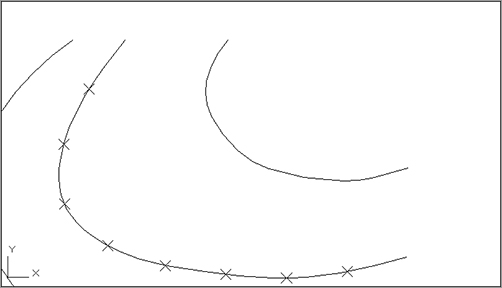
3. At the Select object to divide: prompt, pick the spline contour line that shows Xs in Figure 19-24.
4. The Enter the number of segments or [Block]: prompt that appears next is asking for the number of divisions you want on the selected object. Enter 9↵.
The Command prompt returns, and it appears that nothing has happened. But AutoCAD has placed several point objects on the contour that indicate the locations of the nine divisions you requested. To see these points more clearly, continue with the exercise.
Figure 19-24: Using the Divide command on a polyline
5. Choose Point Style from the Home tab’s Utilities panel or type DDPTYPE↵ to open the Point Style dialog box (Figure 19-25).
6. Click the X point style at the upper-right corner of the dialog box, click the Set Size Relative To Screen radio button, and then click OK.
7. If the Xs don’t appear, enter Re↵. A set of Xs appears, showing the nine divisions (shown earlier in Figure 19-24).
You can also change the point style by changing the Pdmode system variable. When Pdmode is set to 3, the point appears as an X.
The Divide command uses point objects to indicate the division points. You create point objects by using the Point command. They usually appear as dots. Unfortunately, such points are nearly invisible when placed on top of other objects. But, as you’ve seen, you can alter their shape by using the Point Style dialog box. You can use these X points to place objects or references to break the object being divided. (The Divide command doesn’t cut the object into smaller divisions.)
Finding Hidden Node Points
If you’re in a hurry and you don’t want to bother changing the shape of the point objects, you can do the following: Set Running Osnaps to Node. Then, when you’re in Point Selection mode, move the cursor over the divided curve. When the cursor gets close to a point object, the Node Osnap marker appears.
Sketching with AutoCAD
AutoCAD offers the Sketch command, which lets you do freehand drawing. The Sketch command can be set to draw polylines. If you’d like to know more about Sketch, the AutoCAD Help window offers an excellent description of how it works. Click the Help tool (question mark icon) in the InfoCenter, and then on the AutoCAD 2011 Help website, expand the Command Reference listing to Commands S Commands Sketch.
Figure 19-25: The Point Style dialog box

Dividing Objects into Specified Lengths
The Measure command acts just like Divide. However, instead of dividing an object into segments of equal length, the Measure command marks intervals of a specified distance along an object. For example, suppose you need to mark some segments exactly 5˝ apart along the contour. Try the following exercise to see how the Measure command is used to accomplish this task:
1. Erase the X-shaped point objects.
2. Click Measure from the Point flyout in the expanded Draw panel, or type Me↵.
3. At the Select object to measure: prompt, pick the contour at a point closest to its lower endpoint. I’ll explain shortly why this is important.
4. At the Specify length of segment or [Block]: prompt, enter 60↵. The X points appear at the specified distance.
5. Exit without saving this file.
Bear in mind that the point you pick on the object to be measured determines where the Measure command begins measuring. In the previous exercise, for example, you picked the contour near its bottom endpoint. If you picked the top of the contour, the results would be different because the measurement would start at the top, not the bottom.
Marking Off Intervals by Using Blocks Instead of Points
You can also use the Block option under the Divide and Measure commands to place blocks at regular intervals along a line, a polyline, or an arc. Here’s how to use blocks as markers:
1. Be sure the block you want to use is part of the current drawing file.
2. Start either the Divide or Measure command.
3. At the Specify length of segment or [Block]: prompt, enter B↵.
4. At the Enter name of block to insert: prompt, enter the name of a block.
5. At the Align Block with Object? [Yes/No] <Y>: prompt, press ↵ if you want the blocks to follow the alignment of the selected object. (Entering N↵ inserts each block at a 0 angle.)
6. At the Enter the number of segments: prompt, or the Specify length of segment: prompt, enter the number or length of the segments. The blocks appear at regular intervals on the selected object.
One example of using the Block option of Divide or Measure is to place a row of sinks equally spaced along a wall. Alternatively, you might use this technique to make multiple copies of an object along an irregular path defined by a polyline. In civil-engineering projects, you can indicate a fence line by using Divide or Measure to place Xs along a polyline.
Create and edit polylines. Polylines are extremely versatile. You can use them in just about any situation where you need to draw line work that is continuous. For this reason, you’ll want to master polylines early in your AutoCAD training.
Master It Draw the part shown here.

Create a polyline spline curve. Polylines can be used to draw fairly accurate renditions of spline curves. This feature of polylines make them a very useful AutoCAD object.
Master It Try drawing the outline of an object that has no or few straight lines in it, as in the file lowerfairing.jpg, which is included in the Chapter 19 sample files. You can use the methods described in Chapter 14 to import a raster image of your object and then trace over the image using polyline splines.
Create and edit true spline curves. If you need an accurate spline curve, you’ll want to use the Spline tool. Spline objects offer many more fine-tuning options that you won’t find with polylines.
Master It Try tracing over the same image from the previous Master It section, but this time use the Spline tool.
Mark divisions on curves. The Divide and Measure tools offer a quick way to mark off distances on a curved object. This can be a powerful resource in AutoCAD that you may find yourself using often.
Master It Mark off 12 equal divisions of the spline curves you drew in the previous Master It exercise.