
Appendix A: The Bottom Line
Each of The Bottom Line sections in the chapters suggest exercises to deepen skills and understanding. Sometimes there is only one possible solution, but often you are encouraged to use your skills and creativity to create something that builds on what you know and lets you explore one of many possible solutions.
Chapter 1: Exploring the AutoCAD and AutoCAD LT Interface
Use the AutoCAD window. AutoCAD is a typical Windows graphics program that makes use of menus, toolbars, Ribbon panels, and palettes. If you’ve used other graphics programs, you’ll see at least a few familiar tools.
Master It Name the components of the AutoCAD window you can use to select a function.
Solution AutoCAD offers the Quick Access toolbar, the Application menu, Ribbon panels, the navigation bar, and the status bar to give you access to the most common functions.
Get a closer look with the Zoom command. One of the first things you’ll want to learn is how to manipulate your views. The Zoom command is a common tool in graphics programs.
Master It Name at least two ways of zooming into a view.
Solution Choose options from the Zoom flyout in the View tab’s Navigate panel. You can also right-click and select Zoom from the shortcut menu and select Zoom options from the navigation bar’s Zoom flyout.
Save a file as you work. Nothing is more frustrating than having a power failure cause you to lose hours of work. It’s a good idea to save your work frequently. AutoCAD offers an Automatic Save feature that can be a lifesaver if you happen to forget to save your files.
Master It How often does the AutoCAD Automatic Save feature save your drawing?
Solution Automatic Save saves a copy of a drawing every 10 minutes by default. This interval can be modified by the user.
Make changes and open multiple files. As with other Windows programs, you can have multiple files open and exchange data between them.
Master It With two drawings open, how can you copy parts of one drawing into the other?
Solution Use Windows Copy and Paste. Select the parts you want to copy, right-click, and select Clipboard and then Copy. Go to the other drawing and then right-click in the drawing area and select Clipboard and then Paste.
Chapter 2: Creating Your First Drawing
Specify distances with coordinates. One of the most basic skills you need to learn is how to indicate exact distances through the keyboard. AutoCAD uses a simple annotation system to indicate distance and direction.
Master It What would you type to indicate a relative distance of 14 units at a 45 ° angle?
Solution @14<45.
Interpret the cursor modes and understand prompts. AutoCAD’s cursor changes its shape depending on the command that is currently active. These different cursor modes can give you a clue regarding what you should be doing.
Master It Describe the Point Selection cursor and the Pickbox cursor.
Solution The Point Selection cursor is a simple crosshair. The Pickbox cursor is a small square or pickbox.
Select objects and edit with grips. Grips are small squares or arrowheads that appear at key points on the object when they’re selected. They offer a powerful way to edit objects.
Master It How do you select multiple grips?
Solution Hold down the Shift key while clicking the grips.
Use Dynamic Input. Besides grips, objects display their dimensional properties when selected. These dimensional properties can be edited to change an object’s shape.
Master It How do you turn on Dynamic Input? And once it’s on, what key lets you shift between the different dimensions of an object?
Solution The Dynamic Input button on the AutoCAD status bar turns Dynamic Input on and off. When an object is selected, you can move between the dimensional properties by pressing the Tab key.
Get help. AutoCAD’s Help window is thorough in its coverage of AutoCAD’s features. New and experienced users alike can often find answers to their questions thorough the Help window, so it pays to become familiar with it.
Master It What keyboard key do you press for context-sensitive help?
Solution F1.
Display data in a text window. AutoCAD offers the AutoCAD Text Window, which keeps a running account of the commands you use. This can be helpful in retrieving input that you’ve entered when constructing your drawing.
Master It Name a command that displays its results in the AutoCAD Text Window.
Solution The List command.
Display the properties of an object. The Properties palette is one of the most useful sources for drawing information. Not only does it list the properties of an object, it lets you change the shape, color, and other properties of objects.
Master It How do you open the Properties palette for a particular object?
Solution Select the object whose properties you want to view. Right-click the object and select Properties.
Chapter 3: Setting Up and Using AutoCAD’s Drafting Tools
Set up a work area. A blank AutoCAD drawing offers few clues about the size of the area you’re working with, but you can get a rough idea of the area shown in the AutoCAD window.
Master It Name two ways to set up the area of your work.
Solution You can use the Limits command to define the work area, otherwise known as the limits of the drawing. You can also draw a rectangle that is the size of your work area.
Explore the drawing process. To use AutoCAD effectively, you’ll want to know how the different tools work together to achieve an effect. The drawing process often involves many cycles of adding objects and then editing them.
Master It Name the tool that causes the cursor to point in an exact horizontal or vertical direction.
Solution Polar Tracking. Ortho mode can also perform this function.
Plan and lay out a drawing. If you’ve ever had to draw a precise sketch with just a pencil and pad, you’ve probably used a set of lightly drawn guidelines to lay out your drawing first. You do the same thing in AutoCAD, but instead of lightly drawn guidelines, you can use any object you want. In AutoCAD, objects are easily modified or deleted, so you don’t have to be as careful when adding guidelines.
Master It What is the name of the feature that lets you select exact locations on objects?
Solution Object Snap, or Osnap.
Use the AutoCAD modes as drafting tools. The main reason for using AutoCAD is to produce precision technical drawings. AutoCAD offers many tools to help you produce a drawing with the precision you need.
Master It What dialog box lets you set both the grid and snap spacing?
Solution The Drafting Settings dialog box.
Chapter 4: Organizing Objects with Blocks and Groups
Create and insert a symbol. If you have a symbol that you use often in a drawing, you can draw it once and then turn it into an AutoCAD block. A block can be placed in a drawing multiple times in any location, like a rubber stamp. A block is stored in a drawing as a block definition, which can be called up at any time.
Master It Name the dialog box used to create a block from objects in a drawing, and also name the tool to open this dialog box.
Solution The Block Definition dialog box can be opened using the Create tool.
Modify a block. Once you’ve created a block, it isn’t set in stone. One of the features of a block is that you can change the block definition and all the copies of the block are updated to the new definition.
Master It What is the name of the tool used to “unblock” a block?
Solution You can use the Explode tool to break a block down to its component objects. Once this is done, you can modify the objects and then redefine the block.
Understand the annotation scale. In some cases, you’ll want to create a block that is dependent on the drawing scale. You can create a block that adjusts itself to the scale of your drawing through the annotation scale feature. When the annotation scale feature is turned on for a block, the block can be set to appear at the correct size depending on the scale of your drawing.
Master It What setting in the Block Definition dialog box turns on the annotation scale feature, and how do you set the annotation scale of a block?
Solution The Annotative option in the Block Definition dialog box turns on the annotation scale feature. You can set the scales for a block by selecting the block, right-clicking, and selecting Object Scale Add/Delete Scales.
Group objects. Blocks can be used as a tool to group objects together, but blocks can be too rigid for some grouping applications. AutoCAD offers groups, which are collections of objects that are similar to blocks but aren’t as rigidly defined.
Master It How are groups different from blocks?
Solution Objects in a group can be easily edited by turning groups off with a Shift+Ctrl+A keystroke. Also, unlike blocks, groups don’t have a single definition that’s stored in the drawing and defines the group’s appearance. You can copy a group, but each copy is independent of the other groups.
Chapter 5: Keeping Track of Layers and Blocks
Organize information with layers. Layers are perhaps the most powerful feature in AutoCAD. They help to keep drawings well organized and they give you control over the visibility of objects. They also let you control the appearance of your drawing by setting colors, lineweights, and linetypes.
Master It Describe the process of creating a layer.
Solution First, click the Layer Properties Manager tool in the Home tab’s Layers panel. Second, click the New Layer button at the top of the palette. Finally, type the name for your new layer.
Control layer visibility. When a drawing becomes dense with information, it can be difficult to edit. If you’ve organized your drawing using layers, you can reduce its complexity by turning off layers that aren’t important to your current session.
Master It Describe two methods for hiding a layer.
Solution Open the Layer Properties Manager, select a layer, and click the Freeze icon for the layer. You can also open the Layer drop-down list in the Home tab’s Layers panel and click the Freeze icon for the layer you want to hide.
Keep track of blocks and layers. At times, you may want a record of the layers or blocks in your drawing. You can create a list of layers using the log-file feature in AutoCAD.
Master It Where do you go to turn on the log-file feature?
Solution You can open the Options dialog box or use the Logfilemode system variable.
Chapter 6: Editing and Reusing Data to Work Efficiently
Create and use templates. If you find that you’re using the same settings when you create a new drawing file, you can set up an existing file the way you like and save it as a template. You can then use your saved template for any new drawings you create.
Master It Describe the method for saving a file as a template.
Solution After setting up a blank drawing with the settings you use most frequently, choose Save As from the Application menu. In the Save Drawing As dialog box, choose AutoCAD Drawing Template from the Files Of Type drop-down list, give it a name and click Save. In the Template Options dialog box, enter a descriptive name, and click OK to save the template.
Copy an object multiple times. Many tools in AutoCAD allow you to create multiple copies. The Array command offers a way to create circular copies or row and column copies.
Master It What names are given to the two types of arrays in the Array dialog box?
Solution Rectangular and polar.
Develop your drawing. When laying down simple line work, you’ll use a few tools frequently. The exercises in the early part of this book showed you some of these commonly used tools.
Master It What tool can you use to join two lines end to end?
Solution Fillet.
Find an exact distance along a curve. AutoCAD offers some tools that allow you to find an exact distance along a curve.
Master It Name the two tools you can use to mark off exact distances along a curve.
Solution Measure and Divide.
Change the length of objects. You can accurately adjust the length of a line or arc in AutoCAD using a single command.
Master It What is the keyboard alias for the command that changes the length of objects.
Solution The command is len.
Create a new drawing by using parts from another drawing. You can save a lot of time by reusing parts of drawings. The Export command can help.
Master It True or false: The Export command saves only blocks as drawing files.
Solution False. You can use Export any type of object or set of objects in a drawing.
Chapter 7: Mastering Viewing Tools, Hatches, and External References
Assemble the parts. Technical drawings are often made up of repetitive parts that are drawn over and over. AutoCAD makes quick work of repetitive elements in a drawing, as shown in the first part of this chapter.
Master It What is the object used as the basic building block for the unit plan drawing in the beginning of this chapter?
Solution Blocks of a typical unit plan are used to build a floor plan of an apartment building.
Take control of the AutoCAD display. Understanding the way the AutoCAD display works can save you time, especially in a complex drawing.
Master It Name the dialog box used to save views in AutoCAD. Describe how to recall a saved view.
Solution The View Manager dialog box allows you to save views. You can recall views by selecting them from the Views flyout on the View tab’s Views panel.
Use hatch patterns in your drawings. Patterns can convey a lot of information at a glance. You can show the material of an object, or you can indicate a type of view, like a cross section, by applying hatch patterns.
Master It How do you open the Hatch And Gradient dialog box?
Solution Choose Hatch from the Home tab’s Draw panel and then click the Hatch Settings tool in the Hatch Creation tab’s Options panel title bar.
Understand the hatch options. The hatch options give you control over the way hatch patterns fill an enclosed area.
Master It Describe an island as it relates to boundary hatch patterns.
Solution An island is an enclosed object that is found in an area to be hatched.
Use external references. External references are drawing files that you’ve attached to the current drawing to include as part of the drawing. Because external references aren’t part of the current file, they can be worked on at the same time as the referencing file.
Master It Describe how drawing files are attached as external references.
Solution Open the External References palette, click the Attach DWG tool at the upper left, and then locate and select the file you want to attach. You can also click the Attach DWG tool in the External References palette.
Chapter 8: Introducing Printing, Plotting, and Layouts
Understand the plotter settings. Unlike other types of documents, AutoCAD drawings can end up on nearly any size sheet of paper. To accommodate the range of paper sizes, the AutoCAD plotter settings are fairly extensive and give you a high level of control over your output.
Master It Name a few of the settings available in the Plot dialog box.
Solution Paper Size, Plot Area, Plot Scale, and Printer/Plotter Name are a few of the settings available in the Plot dialog box.
Using layout views to control how your plots look. The Layout tabs in AutoCAD offer a way to let you set up how a drawing will be plotted. You can think of the Layout views as a kind of paste-up area for your drawings.
Master It Name some of the items that you see in a layout view.
Solution The layout view shows the paper orientation, plotter margins, and the location of your drawing on the final plotted output.
Add an output device. Typically, AutoCAD will use the Windows system printer as an output device, but often you will find that the printer you use is a dedicated plotter that is not connected to Windows in the usual way. AutoCAD lets you add custom plotters and prints through the Add-A-Plotter Wizard.
Master It How do you start the Add-A-Plotter Wizard?
Solution Click the Plotter Manager tool on the Output tab’s Plot panel, and double-click the Add-A-Plotter Wizard application in the Plotters window.
Store a page setup. Most of the time, you will use the same set of plotter settings for your drawings. You can save plotter settings using the Page Setup feature.
Master It Describe a way to create a page setup. Describe how to retrieve a setup.
Solution Click the Page Setup Manager tool in the Output tab’s Plot panel; then click New in the Page Setup Manager dialog box. Enter a name for your page setup in the New Page Setup dialog box, and then click OK. When you plot your drawing, you can retrieve a page setup by selecting it from the Page Setup drop-down list in the Plot dialog box.
Chapter 9: Understanding Plot Styles
Choose between color-dependent and named plot style tables. Plot styles let you control the way lines are printed on paper. You can control line weights, shading of filled areas, corner treatment of thick lines, and more.
Master It Describe some of the differences between named plot styles and color-dependent plot styles.
Solution Color-dependent plot styles use the color of objects to control line weights and other printed features. Named plot styles can be used to assign printed features to individual objects.
Create a color plot style table. Both color and named plot styles are stored as files. You can create custom plot styles and apply them to any drawing.
Master It In what dialog box do you select and edit plot styles?
Solution Click the Plotter Manager tool in the Output tab’s Plot panel and then open the Plot Styles folder. In the Plot Styles window, locate and double-click the plot style you want to edit.
Edit and use plot style tables. Plot styles give you a lot of control over the appearance of lines in your plotted output.
Master It Name some of the settings offered in the Plot Style Table Editor.
Solution Color, Screening, Lineweight, Line End Style, and Line Join Style are a few of the available options.
Assign named plot styles directly to layers and objects. Named plot styles offer a bit more control over the way lines are plotted. If you choose, you can assign named plot styles to objects, bypassing layer assignments.
Master It Describe a method for assigning a plot style to an object.
Solution You can assign a plot style to an object through the Plot Style setting in the Properties palette. You can also use the Plot Style drop-down list in the Home tab’s Properties panel.
Chapter 10: Adding Text to Drawings
Prepare a drawing for text. AutoCAD offers an extensive set of features for adding text to a drawing, but you need to do a little prep work before you dive in.
Master It Name two things you need to do to prepare a drawing for text.
Solution Set up a layer for your text. Create a text style for your drawing.
Set the annotation scale and add text. Before you start to add text, you should set the annotation scale for your drawing. Once this is done, you can begin to add text.
Master It In a sentence or two, briefly describe the purpose of the annotation scale feature. Name the tool you use to add text to a drawing.
Solution The annotation scale feature converts your text size to the proper height for the scale of your drawing. To add text to a drawing, use the Mtext tool.
Explore text formatting in AutoCAD. Because text styles contain font and text-size settings, you can usually set up a text style and then begin to add text to your drawing. For those special cases where you need to vary text height and font or other text features, you can use the Formatting panel of the Text Editor tab.
Master It What text formatting tool can you use to change text to boldface type?
Solution The Bold button.
Add simple single-line text objects. In many situations, you need only a single word or a short string of text. AutoCAD offers the Single Line text object for these instances.
Master It Describe the methods for starting the single-line text command.
Solution Click the Single Line text tool in the Text panel. Enter DT↵ at the command prompt.
Use the Check Spelling feature. It isn’t uncommon for a drawing to contain the equivalent of several pages of text, and the likelihood of having misspelled words can be high. AutoCAD offers the Check Spelling feature to help you keep your spelling under control.
Master It What option do you select in the Check Spelling dialog box when it finds a misspelled word and you want to accept the suggestion it offers?
Solution Change.
Find and replace text. A common activity when editing technical drawings is finding and replacing a word throughout a drawing.
Master It True or false: The Find And Replace feature in AutoCAD works very differently than the find-and-replace feature in other programs.
Solution False.
Chapter 11: Using Fields and Tables
Use fields to associate text with drawing properties. Fields are a special type of text object that can be linked to object properties. They can help to automate certain text-related tasks.
Master It Name two uses for fields that you learned about in the first part of this chapter.
Solution Fields can be used to update text that labels a block. They can also be used to update text and report the area enclosed by a polyline.
Add tables to your drawing. The Tables feature can help you make quick work of schedules and other tabular data that you want to include in a drawing.
Master It What is the name of the dialog box that appears when you click the Table tool from the Annotate tab’s Tables panel?
Solution Insert Table.
Edit the table line work. Because tables include line work to delineate their different cells, AutoCAD gives you control over table borders and lines.
Master It How do you get to the Cell Border Properties dialog box?
Solution Select the cell or cells in the table, right-click, and choose Borders.
Add formulas to cells. Tables can also function like a spreadsheet by allowing you to add formulas to cells.
Master It What type of text object lets you add formulas to cells?
Solution Field.
Import and export tables. The Table feature allows you to import Microsoft Excel spreadsheets into AutoCAD.
Master It Describe how to import a spreadsheet from Excel into AutoCAD.
Solution Open the spreadsheet and select the cells you want to import. Choose Edit Copy to copy the spreadsheet data into the Clipboard. In AutoCAD, choose Paste Special from the Paste flyout of the Home tab’s Clipboard panel. In the Paste Special dialog box, select AutoCAD Entities, and click OK.
Understand the components of a dimension. Before you start to dimension with AutoCAD, it helps to become familiar with the different parts of a dimension. This will help you set up your dimensions to fit the style of dimensions that you need.
Master It Name a few of the dimension components.
Solution Dimension line, dimension text, extension line, and arrow.
Create a dimension style. As you become more familiar with technical drawing and drafting, you’ll learn that there are standard formats for drawing dimensions. Arrows, text size, and even the way dimension lines are drawn are all subject to a standard format. Fortunately, AutoCAD offers dimension styles that let you set up your dimension format once and then call up that format whenever you need it.
Master It What is the name of the dialog box that lets you manage dimension styles, and how do you open it?
Solution The Dimension Style Manager is the name of the dialog box. You can open it by clicking the Dimension Style tool in the Annotate tab’s Dimensions panel title bar.
Draw linear dimensions. The most common dimension that you’ll use is the linear dimension. Knowing how to place a linear dimension is a big first step in learning how to dimension in AutoCAD.
Master It Name the three locations you’re asked for when placing a linear dimension.
Solution First extension line origin, second extension line origin, and dimension line location.
Edit dimensions. Dimensions often change in the course of a project, so you should know how to make changes to dimension text or other parts of a dimension.
Master It How do you start the command to edit dimension text?
Solution Enter ed↵ at the Command prompt.
Dimension non-orthogonal objects. Not everything you dimension will use linear dimensions. AutoCAD offers a set of dimension tools for dimensioning objects that aren’t made up of straight lines.
Master It Name some of the types of objects for which a linear dimension isn’t appropriate.
Solution Arc and angle between two lines. Linear dimensions can be used for circles in certain situations.
Add a note with a leader arrow. In addition to dimensions, you’ll probably add lots of notes with arrows pointing to features in a design. AutoCAD offers the multileader for this purpose.
Master It What two types of objects does the multileader combine?
Solution Leader lines (arrowhead and line) and text.
Apply ordinate dimensions. When accuracy counts, ordinate dimensions are often used because they measure distances that are similar to coordinates from a single feature.
Master It What AutoCAD feature do you use for ordinate dimensions that isn’t strictly associated with dimensions?
Solution UCS.
Add tolerance notation. Mechanical drafting often requires the use of special notation to describe tolerances. AutoCAD offers some predefined symbols that address the need to include tolerance notation in a drawing.
Master It How do you open the Geometric Tolerance dialog box?
Solution Click the Tolerance tool in the Dimensions panel.
Create attributes. Attributes are a great tool for storing data with drawn objects. You can include as little or as much data as you like in an AutoCAD block.
Master It What is the name of the object you must include in a block to store data?
Solution Attribute definition.
Edit attributes. The data you include in a block is easily changed. You may have several copies of a block, each of which must contain its own unique sets of data.
Master It What is the simplest way to gain access to a block’s attribute data?
Solution Double-click the block to open the Enhanced Attribute Editor.
Extract and export attribute information. Attribute data can be extracted in a number of ways so that you can keep track of the data in a drawing.
Master It How do you start the data-extraction process?
Solution Click the Extract Data tool in the Insert tab’s Linking & Extraction panel to open the Data Extraction Wizard.
Chapter 14: Copying Existing Drawings into AutoCAD
Convert paper drawings into AutoCAD files. AutoCAD gives you some great tools that let you convert your paper drawings into AutoCAD files. Several options are available. Depending on your needs, you’ll find at least one solution that will allow you to convert your drawings quickly.
Master It Describe the different methods available in AutoCAD for converting paper drawings into CAD files.
Solution The methods are tracing with a digitizer, scaling directly from a drawing, scanning and converting with a third-party program, and scanning to a raster file that can then be imported into AutoCAD to be traced over.
Import a raster image. You can use bitmap raster images as backgrounds for your CAD drawings or as underlay drawings that you can trace over.
Master It Import a raster image of your choice, and use the AutoCAD drawing tools to trace over your image.
Solution Click Attach from the Insert tab’s Reference panel or type Attach↵ to open the Select Reference File dialog box. Locate and select the raster image file you want to import. Click Open to open the Attach Image dialog box, and then click OK. Specify an insertion point and scale factor.
Work with a raster image. Once imported, raster images can be adjusted for size, brightness, contrast, and transparency.
Master It Import a raster image of your choice, and fade the image so it appears lighter and with less contrast.
Solution Click a raster image’s border to expose the Image tab. Click and drag the Fade slider to the right so that it’s near the middle of the slider scale, or enter 50 in the Fade input box to the right of the slider. Click OK. The raster image appears faded.
Work with PDF files. AutoCAD allows you to import and control the display of PDF files. This is significant since the PDF file format is so prevalent in the business world.
Master It In a PDF that includes layers, how do you gain access to the layer settings?
Solution Click the imported PDF drawing, and then click the Edit Layers tool that appears in the PDF Underlay tab. You can then control layer visibility through the Underlay Layers dialog box.
Chapter 15: Advanced Editing and Organizing
Use external references (Xrefs). You’ve seen how you can use Xrefs to quickly build variations of a floor plan that contain repetitive elements. This isn’t necessarily the only way to use Xrefs, but the basic idea of how to use Xrefs is presented in the early exercises.
Master It Try putting together another floor plan that contains nothing but the Unit2 plan.
Solution Replace the eight studio units in the Common.dwg file with four of the Unit2 plans.
Manage layers. Once you start to edit complex drawings, you’ll find that you’ll want to save the On/Off or Freeze/Thaw layer states so you can more easily access parts of a drawing. The Layer States Manager offers the ability to save as many layer conditions as you may need in the course of a project.
Master It What part of the Layer States Manager dialog box lets you control the layer properties that are affected by a saved layer state?
Solution The Layer Properties To Restore group in the expanded view of the Layer States Manager.
Use advanced tools: Filter and Quick Select. The Filter and Quick Select tools are great for isolating objects in a crowded drawing. You can select objects by their color or layer assignment. You can select all instances of a specific block.
Master It True or false: The Quick Select tool lets you select a set of objects to limit your selections.
Solution True.
Use the QuickCalc calculator. The QuickCalc calculator offers many standard calculator tools plus a few that you may not see in other calculators.
Master It Name a few of the more unusual features offered by the QuickCalc calculator.
Solution Add feet and inch lengths; find percentages of lengths; obtain coordinates, lengths, and angles graphically from a drawing.
Chapter 16: Laying Out Your Printer Output
Understand Model Space and Paper Space. AutoCAD offers two viewing modes for viewing and printing your drawings. Model Space is where you do most of your work; it’s the view you see when you create a new file. Layouts, also called Paper Space, are views that let you arrange the layout of your drawing, similar to how you would in a page-layout program.
Master It What are the two ways of moving from Model Space to Paper Space?
Solution You can use the Quick View Layouts tool in the status bar to display the Model and Layout preview panels, or you can use the Model and Layout tabs in the lower-left corner of the drawing area.
Work with Paper Space viewports. While in Paper Space, you can create views into your drawing using viewports. You can have several viewports, each showing a different part of your drawing.
Master It Name some of the ways you can enlarge a view in a viewport.
Solution You can double-click inside a viewport and then use the Zoom tool to enlarge the view. You can also use the Viewport Scale setting in the status bar to set the scale of the view.
Create odd-shaped viewports. Most of the time, you’ll probably use rectangular viewports, but you have the option to create a viewport of any shape.
Master It Describe the process for creating a circular viewport.
Solution In Paper Space, draw a circle. Next, click Create From Object from the View tab’s Viewports panel, and then follow the prompts.
Understand line weights, linetypes, and dimensions in Paper Space. You can get an accurate view of how your drawing will look on paper by making a few adjustments to AutoCAD. Your layout view will reflect how your drawing will look when plotted.
Master It Name the two dialog boxes you must use to display line weights in a layout view.
Solution The Layer Properties Manager to set up line weights and the Lineweight Settings dialog box.
Chapter 17: Making “Smart” Drawings with Parametric Tools
Use parametric drawing tools. Parametric drawing tools enable you to create an assembly of objects that are linked to each other based on geometric or dimensional properties. With the parametric drawing tools, you can create a drawing that automatically adjusts the size of all its components when you change a single dimension.
Master It Name two examples given in the beginning of the chapter of a mechanical assembly that can be shown using parametric drawing tools.
Solution The examples are a crankshaft and piston and a Luxo lamp.
Connect objects with geometric constraints. You can link objects together so that they maintain a particular orientation to each other.
Master It Name at least six of the geometric constraints available in AutoCAD.
Solution The constraints are coincident, collinear, concentric, fix, parallel, perpendicular, horizontal, vertical, tangent, smooth, symmetric, and equal.
Control sizes with dimensional constraints. Dimensional constraints, in conjunction with geometric constraints, let you apply dimensions to an assembly of objects to control the size of the assembly.
Master It Name at least four dimensional constraints.
Solution The dimensional constraints are linear, horizontal, vertical, aligned, radius, diameter, and angular. In addition, a tool allows you to convert a normal dimension into a dimensional constraint.
Use formulas to control dimensions. Dimensional constraints allow you to link dimensions of objects so that if one dimension changes, another dimension follows.
Master It What example was used to show how formulas can be used with dimensional constraints?
Solution A circle’s diameter was linked to the width dimension of a drawing of a simple part.
Put constraints to use. Constraints can be used in a variety of ways to simulate the behavior of real objects.
Master It Name at least three geometric or dimensional constraints used in the piston.dwg sample file to help simulate the motion of a piston and crankshaft.
Solution The geometric constraints used were horizontal, parallel, fix, and coincident. The dimensional constraints used were horizontal, vertical, aligned, and diameter.
Chapter 18: Using Dynamic Blocks
Explore the Block Editor. To create dynamic blocks, you need to become familiar with the Block Editor. You can use the Block Editor to modify existing blocks in your drawing.
Master It What does the Edit Block Definition dialog box allow you to do?
Solution The Edit Block Definition dialog box lets you select the block you want to edit from a list of blocks in the drawing.
Create a dynamic block. Dynamic blocks are blocks to which you add grips that let you modify the block in a number of different ways.
Master It Name some of the features of the Block Editor that let you add additional grip editing functions to a block.
Solution Geometric constraints, dimensional constraints, parameters, and actions.
Add Scale and Stretch actions to a parameter. You can set up a dynamic block to perform multiple operations with a single grip.
Master It What do you need to do to have one grip perform two functions?
Solution Use a single parameter to control two actions.
Add more than one parameter for multiple grip functions. In addition to having one grip perform multiple operations, you can add as many grips as you need to make your block even more customizable.
Master It What feature do you use to set up a list of options for a block?
Solution The Block Table.
Create multiple shapes in one block. Many of the dynamic-block functions let you adjust the shape of the original block. Another feature lets you choose completely different shapes for the block.
Master It When a block uses the Visibility parameter to set up different shapes, how do you select a different block shape in the drawing?
Solution Click the block, and then click the Visibility grip. A list appears showing the different shapes that are available.
Rotate objects in unison. Blocks can be set up so the action of one set of objects affects another set. This chapter gives the example of rotating objects in unison.
Master It Name the dimensional constraint that was used in the object rotation example in this chapter.
Solution Angular.
Fill in a space automatically with objects. A dynamic block can help you automate the addition of repetitive elements to your drawing.
Master It What is the name of the action used to produce an array of an object in a block when the block is stretched?
Solution The Array action.
Create and edit polylines. Polylines are extremely versatile. You can use them in just about any situation where you need to draw line work that is continuous. For this reason, you’ll want to master polylines early in your AutoCAD training.
Master It Draw the part shown here.
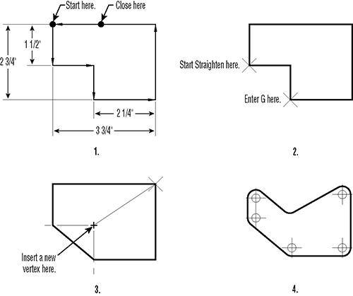
Solution There are many ways to create this drawing. Use these instructions as guidelines and not the only way to create the drawing:
1. Open a new file called PART14 using the acad.dwt template. Set the Snap spacing to 0.25, and be sure Snap mode is on. Use the Pline command to draw the object shown in step 1 of the drawing shown previously. Start at the upper-left corner, and draw in the direction indicated by the arrows. Use the Close option to add the last line segment.
2. Start the Pedit command, select the polyline, and then type E↵ to issue the Edit Vertex option. Press ↵ until the X mark moves to the first corner, shown here. Enter S↵ for the Straighten option.
3. At the Enter an option prompt, press ↵ twice to move the X to the other corner, shown in step 2 of the drawing. Press G↵ for Go to straighten the polyline between the two selected corners.
4. Press ↵ three times to move the X to the upper-right corner, and then enter I↵ for Insert. Pick a point as shown in step 3 of the drawing. The polyline changes to reflect the new vertex. Enter X↵ to exit the Edit Vertex option, and then press ↵ to exit the Pedit command.
5. Start the Fillet command, use the Radius option to set the fillet radius to 0.30, and then use the Polyline option and pick the polyline you just edited. All the corners become rounded to the 0.30 radius. Add the 0.15 radius circles as shown in step 4 of the drawing, and exit and save the file.
Create a polyline spline curve. Polylines can be used to draw fairly accurate renditions of spline curves. This feature of polylines make them a very useful AutoCAD object.
Master It Try drawing the outline of an object that has no or few straight lines in it, as in the file lowerfairing.jpg, which is included in the Chapter 19 sample files. You can use the methods described in Chapter 14 to import a raster image of your object and then trace over the image using polyline splines.
Solution Import a raster image by using the Attach tool in the Insert tab’s Reference panel. Use the Polyline tool to trace over the image. Use short, straight polyline segments while you trace. After you place each polyline, double-click it and select the Spline option. Once you change the line to a spline curve, it may shift away from the original line you traced over. Click the polyline, and then adjust the grips so the line fits over the raster image.
Create and edit true spline curves. If you need an accurate spline curve, you’ll want to use the Spline tool. Spline objects offer many more fine-tuning options that you won’t fine with polylines.
Master It Try tracing over the same image from the previous Master It section, but this time use the Spline tool.
Solution Import a raster image by using the Attach tool in the Insert tab’s Reference panel. Use the Spline tool to trace over the image. As you draw the spline, select control points that are closer together for tighter curves. The closer the control points are, the tighter you can make the curve. Notice that, unlike with a polyline spline, you don’t have to readjust the curve after it’s been placed.
Mark divisions on curves. The Divide and Measure tools offer a quick way to mark off distances on a curved object. This can be a powerful resource in AutoCAD that you may find yourself using often.
Master It Mark off 12 equal divisions of the spline curves you drew in the previous Master It exercise.
Solution Choose Divide from the Point flyout in the expanded Draw panel, click the spline, and then enter 12↵. If you don’t see the points that mark off the divisions, type DDPTYPE↵, select the X point style, and click OK.
Chapter 20: Getting and Exchanging Data from Drawings
Find the area of closed boundaries. There are a number of ways to find the area of a closed boundary. The easiest way is also perhaps the least obvious.
Master It Which AutoCAD feature would you use to quickly find the area of an irregular shape like a pond or lake?
Solution Hatch.
Get general information. A lot of information that is stored in AutoCAD drawings can tell you about the files. You can find out how much memory a file uses as well as the amount of time that has been spent editing the file.
Master It What feature lets you store your own searchable information about a drawing file, and how do you get to this feature?
Solution You can open the Properties dialog box by choosing Drawing Utilities Drawing Properties from the Application menu.
Use the DXF file format to exchange CAD data with other programs. Autodesk created the DXF file format as a means of sharing vector drawings with other programs.
Master It Name some of the versions of AutoCAD you can export to using the Save As option.
Solution 2010, 2007, 2004, 2002, and R12.
Use AutoCAD drawings in page-layout programs. AutoCAD drawings find their way into all types of documents, including brochures and technical manuals. Users are often asked to convert their CAD drawings into formats that can be read by page-layout software.
Master It Name some file formats, by filename extension or type, which page-layout programs can accept.
Solution PDF (.pdf), WMF (.wmf), EPS (.eps), and a wide variety of bitmap image files.
Use OLE to import data. You can import data into AutoCAD from a variety of sources. Most sources, such as bitmap images and text, can be imported as native AutoCAD objects. Other sources may need to be imported as OLE objects.
Master It To link imported data to a source program through OLE, what dialog box would you use?
Solution Paste Special.
Chapter 21: Creating 3D Drawings
Know the 3D modeling workspace. When you work in 3D, you need a different set of tools from those for 2D drafting. AutoCAD offers the 3D Modeling workspace, which provides the tools you need to create 3D models.
Master It Name some of the Ribbon panels that are unique to the 3D Modeling workspace.
Solution Modeling, Solid Editing, Visual Styles, Edge Effects, Lights, Sun & Location, Materials, Palettes, Animations, and Render.
Draw in 3D using solids. AutoCAD offers a type of object called a 3D solid that lets you quickly create and edit shapes.
Master It What does the Presspull command do?
Solution Presspull lets you press or pull a 3D solid shape from another 3D solid. It can also be used to press or pull a closed 2D object drawn on the surface of a solid.
Create 3D forms from 2D shapes. The Modeling panel offers a set of basic 3D shapes, but other tools enable you to create virtually any shape you want from 2D drawings.
Master It Name the command that lets you change a closed 2D polyline into a 3D solid.
Solution Extrude.
Isolate coordinates with point filters. When you’re working in 3D, selecting points can be a complicated task. AutoCAD offers point filters to let you specify the individual X, Y, and Z coordinates of a location in space.
Master It What does the .XY point filter do?
Solution The .XY point filter lets you select an X,Y coordinate, after which you can specify a Z coordinate as a separate value.
Move around your model. Getting the view you want in a 3D model can be tricky.
Master It Where is the drop-down list that lets you select a view from a list of predefined 3D views?
Solution The Home tab’s View panel contains a drop-down list that offers predefined 3D views.
Get a visual effect. At certain points in your model making, you’ll want to view your 3D model with surface colors and even material assignments. AutoCAD offers several ways to do this.
Master It What are the steps to take to change the view from Wireframe to Conceptual?
Solution Click the Visual Styles drop-down list, and select Conceptual.
Turn a 3D view into a 2D AutoCAD drawing. Sometimes, it’s helpful to convert a 3D model view into a 2D AutoCAD drawing. AutoCAD offers the Flatshot tool, which quickly converts a 3D view into a 2D line drawing.
Master It What type of object does Flatshot create?
Solution A block or drawing file.
Chapter 22: Using Advanced 3D Features
Master the User Coordinate System. The User Coordinate System (UCS) is a vital key to editing in 3D space. If you want to master 3D modeling, you should become familiar with this tool.
Master It Name some of the predefined UCS planes.
Solution Front, Back, Left, Right, Top, Bottom.
Understand the UCS options. You can set up the UCS orientation for any situation. It isn’t limited to the predefined settings.
Master It Give a brief description of some of the ways you can set up a UCS.
Solution Object orientation, selection of three points, rotation about an axis, selection of a Z axis direction, and selection of the view plane.
Use viewports to aid in 3D drawing. In some 3D modeling operations, it helps to have several different views of the model through the Viewports feature.
Master It Name some of the predefined standard viewports offered in the Viewports dialog box.
Solution Two: Vertical, Two: Horizontal, Three: Right, Three: Left, Three: Above, Three: Below, Three: Vertical, Three: Horizontal, Four: Equal, Four: Right, and Four: Left.
Create complex 3D surfaces. You aren’t limited to straight, flat surfaces in AutoCAD. You can create just about any shape you want, including curved surfaces.
Master It What tool did you use in this chapter’s chair exercise to convert a surface into a solid?
Solution The Thicken tool.
Create spiral forms. Spiral forms frequently occur in nature, so it’s no wonder that we often use spirals in our own designs. Spirals are seen in screws, stairs, and ramps as well as in other manmade forms.
Master It Name the commands used in the example in the section “Creating Spiral Forms,” and name two elements that are needed to create a spiral.
Solution The commands are Helix and Sweep. A helix and a profile are needed.
Create surface models. You can create a 3D surface by connecting a series of lines that define a surface contour. You can create anything from a 3D landscape to a car fender using this method.
Master It What is the tool used to convert a series of lines into a 3D surface?
Solution Loft.
Move objects in 3D space. You can move objects in 3D space using tools that are similar to those for 2D drafting. But when it comes to editing objects, 3D modeling is much more complex than 2D drafting.
Master It What does the Rotate gizmo do?
Solution It lets you graphically determine the axis of rotation for an object being rotated.
Chapter 23: Rendering 3D Drawings
Simulate the sun. One of the more practical uses of AutoCAD’s rendering feature is to simulate the sun’s location and resulting shadows. You can generate shadow studies for any time of the year in any location on the earth.
Master It Name three items that can be set to position the sun in relation to your model.
Solution Date, time, and geographic location.
Use materials. AutoCAD lets you create materials that you can apply to the objects in your model to simulate a realistic appearance.
Master It Name the parts of AutoCAD that can be used to create materials, and describe some of their features.
Solution The Materials Browser and Materials Editor let you create materials that you can then apply to objects in your model. You use a bitmap image to simulate a texture. You can also control a material’s transparency. Other features allow you to set the size of the material over the surface of an object.
Create effects using materials and lights. You can use materials and lights together to control the appearance of your model.
Master It Name the part of the example model in this chapter that was used to show how a material can appear to glow.
Solution Ceiling lights.
Apply and adjust texture maps. Texture maps can be used to create a number of effects in your model. You can use a brick texture map that repeats over a surface to simulate a brick wall, or you can use a photograph of a building to turn a box into a building.
Master It What is the name of the feature that lets you graphically adjust a texture map on an object?
Solution Mapping Gizmo.
Understand the rendering options. In addition to adjusting the materials and lighting to control the look of your rendering, you can make other adjustments to your rendering through the Render panel and the Render window.
Master It Name some of the right-click menu options that appear for image filenames in the Render window.
Solution Render Again, Save, Save Copy, Make Render Settings Current, Remove From The List, and Delete Output File.
Add cameras for better view control. When you create a view using the View Manager dialog box, you’re actually creating a camera. Cameras are objects that let you control the orientation and view target for a view, among other things.
Master It Name some of the options you can set to control a camera.
Solution Name, camera location, height, target location, focal length, and front and back clipping.
Print your renderings. You can save your rendered views as bitmap files using the Render window. If you prefer, you can also have AutoCAD include a rendering in a layout. You can include different renderings of the same file in a single layout.
Master It Give a general description of the process for setting up a rendered viewport in a layout.
Solution Create a viewport, and then set up the view you want for the viewport using the View Manager dialog box. Select the viewport’s border, right-click, and select a Shade Plot menu option.
Simulate natural light. When you want to get a more accurate rendition of the lighting effects on your model, you can use some of the advanced rendering features that simulate natural light.
Master It Name the two setting groups you need to use to render an interior view accurately.
Solution The Global Illumination and Final Gather groups of the Advanced Render Settings palette.
Chapter 24: Editing and Visualizing 3D Solids
Understand solid modeling. Solid modeling lets you build 3D models by creating and joining 3D shapes called solids. There are several built-in solid shapes called primitives, and you can create others using the Extrude tool.
Master It Name some of the built-in solid primitives available in AutoCAD.
Solution Box, wedge, cone, sphere, cylinder, pyramid, torus, and polysolid.
Create solid forms. You can use Boolean operations to sculpt 3D solids into the shape you want. Two solids can be joined to form a more complex one, or you can remove one solid from another.
Master It Name the three Boolean operations you can use on solids.
Solution Intersection, subtraction, and union.
Create complex solids. Besides the primitives, you can create your own shapes based on 2D polylines.
Master It Name three tools that let you convert closed polylines and circles into 3D solids.
Solution Extrude, Revolve, and Sweep.
Edit solids. Once you’ve created a solid, you can make changes to it using the solid-editing tools offered on the Solid Editing panel.
Master It Name at least four of the tools found on the Solid Editing panel.
Solution The tools found on the Solid Editing panel are Union, Subtract, Intersect, Interfere, Slice, Thicken, tools on the Edges flyout, tools on the Faces flyout, tools on the Separate flyout, Convert To Solid, and Convert To Surface.
Streamline the 2D drawing process. You can create 3D orthogonal views of your 3D model to create standard 2D mechanical drawings.
Master It What is the name of the tool in the Solid Editing panel that lets you create a 2D drawing of a 3D model?
Solution Flatshot.
Visualize solids. In addition to viewing your 3D model in a number of different orientations, you can view it as if it were transparent or cut in half.
Master It What is the name of the command that lets you create a cut view of your 3D model?
Solution Sectionplane.
Chapter 25: Exploring 3D Mesh and Surface Modeling
Create a simple 3D mesh. Mesh modeling allows you to create more organic 3D forms by giving you unique smoothing and editing tools. You can start your mesh model by creating a basic shape using the mesh primitives.
Master It Name at least six mesh primitives available on the Primitives panel of the Mesh Modeling tab.
Solution The mesh primitives are box, cylinder, cone, sphere, pyramid, wedge, and torus.
Edit faces and edges. The ability to edit faces and edges is essential to creating complex shapes with mesh objects.
Master It Name the tool that is used to divide a face into multiple faces.
Solution The Refine Mesh tool.
Create mesh surfaces. The Mesh primitives let you create shapes that enclose a volume. If you just want to model a smooth, curved surface in 3D, you might find the surface mesh tools helpful.
Master It How many objects are needed to use the Edge Surface tool?
Solution Four.
Convert meshes to solids. You can convert a mesh into a 3D solid to take advantage of many of the solid editing tools available in AutoCAD.
Master It Name at least two tools you can use on a solid that you cannot use on a mesh.
Solution Union, Subtract, Intersect, Interfere, any of the edge or face editing tools on the Solid Editing panel of the Home tab.
Understand 3D surfaces. 3D surfaces can be created using some of the same tools you use to create 3D solids.
Master It Name at least two tools you can use to create both 3D solids and 3D surfaces.
Solution Any of the following: Loft, Sweep, Extrude, and Revolve.
Edit 3D surfaces. AutoCAD offers a wide range of tools that are unique to 3D surfaces.
Master It Name at least four tools devoted to CV editing.
Solution Any of the following: CV Edit bar, Convert To NURBS, Show CV, Hide CV, Surface Rebuild (Rebuild), Surface CV – Add (or just CV Add), and Surface CV – Remove (or just CV Remove).
Chapter 26: Using the Express Tools
Use enhancements straight from the source. The Express tools have been around for a while and were originally intended to show what could be done with customization. Many users have come to rely on some of these tools.
Master It In which panel will you find the Align Space tool?
Solution Layout.
Put AutoLISP to work. AutoLISP is a macro language that gives you the ability to create your own commands.
Master It Name the filename extension for AutoLISP programs.
Solution The filename extension is .lsp.
Chapter 27: Exploring AutoLISP
Understand the interpreter. One of the simplest ways to start using AutoLISP is to enter an AutoLISP expression directly into the command line.
Master It Give an example of an AutoLISP formula that performs a simple math function.
Solution (+ 2 2)
Use arguments and functions. AutoLISP needs two elements, an argument and an expression, to do any work.
Master It Which is the function in the following AutoLISP expression?
(+ 45 33)
Solution +
Create a simple program. You can input a simple program directly into AutoCAD by entering it through the command line.
Master It Name a function that pauses an AutoLISP program for user input.
Solution Getpoint or any of the Get functions.
Select objects with AutoLISP. AutoLISP offers an expression that lets you select objects and then perform some operation on the set of objects.
Master It What function lets you select objects, and what AutoLISP feature do you use to store your selection?
Solution Ssget, variable.
Control the flow of an AutoLISP program. You can set up an AutoLISP program to test for conditions and perform different operations depending on the result.
Master It Name some functions that test for a condition.
Solution If, While, Foreach.
Convert data types. The functions in AutoLISP are designed to work with their own types of data. For example, math functions work only with numbers, and string operations work only with text. If you need to use the result of a math function in text, you can convert the number into text.
Master It What is the name of the function that converts an angle in radians to text?
Solution Angtos.
Store your programs as files. You can save your AutoLISP program in a text editor like Windows Notepad and then later have AutoCAD retrieve your program for use.
Master It What is the filename extension for AutoLISP programs?
Solution .lsp
Chapter 28: Customizing Toolbars, Menus, Linetypes, and Hatch Patterns
Use workspaces. Often with AutoCAD, you find that you have different sets of panels or toolbars open to perform specific tasks. You might have one set of Ribbon panels for editing text and dimensions, whereas another set is more useful for design. Using workspaces is a great way to organize your different editing modes.
Master It Where do you find the Customize option for workspaces?
Solution The Workspace drop-down menu or the Workspace Switching tool.
Customize the user interface. In addition to using workspaces to organize tools and Ribbon panels, you can customize the AutoCAD interface to make it fit the way you like to work. You can add tools to Ribbon panels or even create your own tools for operations you perform frequently.
Master It What does the Customizations In All Files group display?
Solution Interface elements like toolbars, menus, ribbons, and so on.
Create macros in tools and menus. A macro is a set of instructions that performs more complex operations than single commands. Macros are often built on commands with additional predefined responses to help speed data input.
Master It What does the ^C do in a macro?
Solution The ^C is equivalent to pressing the Esc key.
Edit keyboard shortcuts. Keyboard shortcuts can help improve your speed when drawing in AutoCAD. They can reduce several clicks of the mouse to a simple keystroke. AutoCAD lets you create custom shortcuts for your favorite commands.
Master It What is the keyboard shortcut for Copy?
Solution Co↵.
Save, load, and unload your customizations. To keep your customizations organized, you can save new toolbars, menus, and Ribbons as files that you can load on demand. When you save your custom elements as a file, you can move them to other computers.
Master It Name the tab that contains the group you use to save your custom elements.
Solution Transfer tab.
Understand the Diesel macro language. If you’re adventurous, you may want to try your hand at creating more-complex macros. The Diesel macro language is an easy introduction to AutoCAD macro customization and is most useful in controlling the behavior in menu options.
Master It What does the expression $(getvar, blipmode) do?
Solution It returns 1 or 0 depending on the current state of the Blipmode system variable.
Create custom linetypes. AutoCAD offers a number of noncontinuous linetypes, and you may find them adequate for most of your work. But every now and then, you may need a specific linetype that isn’t available. Creating custom linetypes is easy once you understand the process.
Master It What is the purpose of a negative value in the linetype code?
Solution A blank or break in the line.
Create hatch patterns. Like linetypes, the hatch patterns provided by AutoCAD will probably fill most of your needs. But every now and then, you may need to produce a specific pattern.
Master It How are a hatch pattern code and a linetype code similar?
Solution They both use numeric values to describe lines.
Chapter 29: Managing and Sharing Your Drawings
Share drawings over the Internet. As a drafter or designer, it’s very likely that you’ll be involved in collaborative efforts, which means you’ll have to share your work with others. The Internet has made it much easier to do this.
Master It Why is eTransmit important for sending AutoCAD drawings over the Internet?
Solution An AutoCAD drawing can have many different external files associated with it, such as fonts, Xrefs, and image files. eTransmit offers a quick way to gather these files into one place or into a single archive file.
ePublish your drawings. Autodesk offers the DWF drawing format, which lets non-CAD users view and add comments to simplified versions of your drawings. You can use the Publish feature to create a single DWF file from several drawings.
Master It True or false: The Publish feature can be used to plot multiple drawings in the background.
Solution True.
Manage your drawings with DesignCenter and the tool palettes. The DesignCenter is a great tool for managing your drawings’ resources, like blocks, custom linetypes, and other elements.
Master It True or false: The DesignCenter has the capacity to scale a block automatically to the correct size when moving from metric to Imperial drawings.
Solution True.
Establish office standards. AutoCAD allows for a wide range of settings in a drawing. For this reason, it’s a good idea to create standards for the way drawings are set up.
Master It Name the filename extension for an AutoCAD drawing standards file.
Solution .dws.
Convert multiple layer settings. If you exchange files with another office, you may find that their layer scheme is different from yours. AutoCAD offers the Layer Translator to help you translate layer names from an unfamiliar drawing to names you’re more comfortable with.
Master It Name the filename extensions of the types of files that you can use as a template for layer-name translations.
Solution .dwg, .dws, and .dwt.
Chapter 30: Keeping a Project Organized with Sheet Sets
Understand sheet sets. The sheet set feature is like a database that automatically keeps track of drawings and drawing resources for your projects. To use sheets sets successfully, you need to make sure the Sheet Set Manager is aware of all the drawings and resources used in a project.
Master It Name the two main categories of files that sheets sets use and that were mentioned at the beginning of this chapter.
Solution Reference files and sheet files.
Create a sheet set from an existing project. If you have existing project files, you can set up a sheet set to work with them.
Master It Name the option on the first page of the Create Sheet Set Wizard that lets you set up a sheet set for an existing project.
Solution The Existing Drawings radio button.
Manage title blocks and cross-references. When the Sheet Set Manager is aware of a drawing or drawing resource, you can automate the creation of sheets such as elevations and sections. You can also control the naming and numbering of drawings in a set through the Sheet Set Manager.
Master It What is the name of the right-click option that lets you change the name and number of a drawing?
Solution Rename & Renumber.
Customize sheet sets. To use sheets sets to their full potential, you should create title blocks and callout blocks that are sheet set aware so they can communicate with the Sheet Set Manager.
Master It What is the name of the object you must include in a block to store data?
Solution Attribute definition.
Archive, publish, and eTransmit sheet sets. As a project starts to grow, you’ll have to keep track of sheet and reference drawings as well as other drawing resources. Because the Sheet Set Manager is already aware of all the files needed for a project, you can use it to help keep track of project files.
Master It Name the three AutoCAD features that help you manage your files.
Solution Archive, Publish, and eTransmit.