
7 Technical Topics
LRRY. LRRY is a walking, fire-breathing kinetic sculpture by artist Lyle Rowell. Constructed from scrap car and motorcycle parts, LRRY is powered by an automobile engine from a Citröen 2CV and is shown here at Mutate Britain’s 2009 exhibition in London, England. Graffiti art by Elate and Vibez.
Two studio flash units were used: one snooted and camera left, and the other behind the machine for backlighting. One device was fired with a radio trigger, and the other responded to an optical slave. Manual power output on both flash units. No gels were used on the studio units, to provide bluish light as a deliberate contrast to the yellow propane flame.
This chapter covers fairly technical material: how modern flash technology works. I think it’s pretty useful to know this stuff, as you’re always better equipped to solve a problem if you understand the underlying reasons for why things are the way they are, but this isn’t the easiest part of the book to digest. If you skip this chapter, it might be worth referring back to it later.
7.1Canon EOS flash metering
As described previously, automatic flash metering on EOS cameras relies on the camera and flash unit working together in unison, and is essentially handled independently of metering for ordinary ambient light. Canon has, over the years, built two fundamental types of flash metering technologies into its EOS cameras: TTL, which is used only by film cameras, and E-TTL, which is used by all digital cameras as well as post-1995 film cameras. Here’s how it all functions.

7.1 A digital EOS 500D (Rebel T1i) camera with Speedlite 430EX flash unit, attached to an optional SB-E2 flash bracket. Like all EOS digital cameras, this model uses E-TTL flash metering.
7.2TTL flash metering
“Through-the-lens,” or TTL flash metering, was pioneered by Olympus in the mid-1970s. The first Canon camera to use it was the legendary manual- focus T90 of 1986, and the feature was standardized in the EOS film lineup a year later. While virtually all EOS film cameras use TTL, it’s now obsolete technology and not used on any digital camera.
TTL flash metering measures the amount of flash-generated light that bounces off the subject and back into the lens. The light sensor can’t sit between the lens and the film, since that would obviously block incoming light, so it’s positioned at the bottom of the mirror box. It actually detects the light reflecting off the surface of the film itself, and is thus known as an off-the-film (OTF) sensor. The light produced by the flash unit is shut off, or “quenched,” when the camera detects that enough light has been reflected back and that a satisfactory flash exposure must have occurred. ![]() 7.3
7.3

7.2 The base of a film camera’s mirror box, looking from the film side of the camera. The small lens covers the TTL flash sensor. The other openings are for the recessed autofocus sensors.

7.3
While TTL is similar to autoflash (section 10.7) in that the scene-illuminating flash pulse is measured in real time as it’s emitted by the flash tube, it differs significantly since the flash sensor is inside the camera and not on the outside of the flash unit. For this reason TTL flash must be designed into the camera from the ground up, and camera and flash unit must be able to communicate with each other. Technologically, this is very different from both manual flash and autoflash, which rely solely on a simple “produce light right now!” sync command from the camera body.
TTL records only the light that makes up the final image. Unlike autoflash sensors built into a flash unit, it can’t be fooled by reflective objects outside the frame. TTL doesn’t care if any light-modifying devices or filters are placed on the flash or lens, since it records reflected light and not the output of a device. TTL is highly automated, freeing you from the burden of calculating the distance from flash to subject or adjusting flash output settings.
Almost every EOS film camera supports TTL, with two exceptions described in section 7.6.1.

7.4 The Speedlite 540EZ, shown here on an EOS 5/A2E, was the top of the line flash unit for TTL-only film cameras.
7.2.1TTL limitations
TTL has many drawbacks. The flash sensors can easily be fooled by highly reflective surfaces. TTL is designed to measure flash reflections off typical color negative film and can have subtle metering problems with other film types. TTL doesn’t handle multiple flash units very well, and can’t work wirelessly. And it can’t be reliably mixed with manual flash.
TTL-equipped cameras have only one, three, or four flash sensors, depending on the model, versus the dozens of ambient light metering zones in modern bodies. Canon TTL flash sensors tend to misread off-center subjects, and can’t distinguish between far-off reflective objects and less reflective objects close at hand. But these aren’t the reasons TTL flash metering is no longer used today.
KEY POINT
TTL-only flash units (Speedlite E, EG, and EZ models) cannot meter automatically when used with a digital EOS camera. The same applies to EX Speedlites if set to TTL mode.
7.2.2Digital cameras and TTL flash
The rise of digital photography caused a huge problem for engineers at Canon and other companies when they discovered that TTL flash doesn’t work properly with digital sensors, which reflect light differently from film. Fortunately, TTL flash’s successor, E-TTL (section 7.4), was already on the market and was successfully adapted for the new digital world.
When shopping for an automatic flash unit for a digital EOS camera, be sure to avoid TTL-only devices such as non-EX (E or EZ) Canon Speedlite models, no matter what sellers may claim about their compatibility. TTL-only flash units, or any EX Speedlite set to TTL mode, will either fire at full power or not at all when used on a digital camera. For a comprehensive list, please see appendix C.
7.3A-TTL flash metering
“Advanced” TTL is an obsolete flash metering variant available to TTL- compatible EOS film cameras when a Speedlite EZ model is attached.
In A-TTL mode, the flash unit fires a brief supplementary pulse of light during the metering phase, before the shutter actually opens. Speedlite EZ units have a special sensor to record light bouncing back from this preflash, and that data is factored into normal TTL operation.
The preflash occurs when the shutter release button is pressed halfway. It’s either invisible infrared from a secondary tube or visible white light from the main tube, depending on the model and the position of the flash head.
A-TTL, despite its name, offers no real advantage over regular TTL and was abandoned when E-TTL was introduced.

7.5 The round lens covers the A-TTL sensor. The glowing red area to the left of the sensor is the near-infrared prefire for A-TTL metering. It’s basically an ordinary flash tube hidden behind a light-blocking plastic panel.
7.4E-TTL flash metering
“Evaluative through-the-lens” (E-TTL or preflash) flash metering was introduced in 1995 and is the current way that all EOS cameras meter for flash. It’s completely incompatible with TTL, and uses the same evaluative light sensor as regular ambient lighting. ![]() 7.6
7.6

7.6

7.7 The pentaprism from an EOS camera. The orange circuit board behind the clear plastic lens contains the ambient light sensor. This assembly is buried inside the top of the camera and can’t be seen from the outside.
E-TTL works by firing a low-powered preflash of known brightness from the main flash tube. The reflectance of the preflash-illuminated scene is measured using the camera’s normal evaluative light meter, and then the camera’s computer calculates the light required to achieve a mid-toned subject. The camera flips up the mirror, opens the shutter, and instructs the flash unit to fire the scene-illuminating pulse at the pre-computed output level.
KEY POINT
E-TTL flash fires at least one low-power test flash for metering purposes prior to the actual scene- illuminating flash.
There are some important points here. First, the E-TTL preflash occurs right before the shutter opens and not when the shutter release is pressed halfway. It may be surprising to learn that E-TTL actually fires a preflash at all. Under normal circumstances, it happens so quickly that the preflash is difficult to notice—though it is quite obvious when using flash exposure lock (FE lock) or second-curtain sync and a long shutter setting. However, the preflash explains why a slight flash is visible when looking through the viewfinder: the final illuminating flash can’t be seen through the view-finder since the mirror is up at that point.
Second, the preflash is analyzed by the same evaluative metering system that the camera uses to meter normal ambient light. This means it meters through the lens and is harder to fool than external sensors; it isn’t confused by bounced light, doesn’t read anything off the surface of the film, and examines as many separate zones of the image as the metering system has.
E-TTL is generally superior to its predecessors at applying subtle and natural fill flash to daylight photographs. E-TTL exposure is also linked to the current AF focus point, which, in theory, results in finer-grained exposure biasing than TTL flash sensor systems (which only have one or three zones).
E-TTL requires both an E-TTL camera and an E-TTL flash unit. All Canon- designed EOS digital cameras, and EOS film cameras made since the mid-1990s, support it, but older TTL cameras can’t use it. All Canon Speedlite flash units with “EX” in the name speak E-TTL.

7.8 Canon EOS digital cameras and Speedlite EX flash units are all interchangeable. You could even put an enormous 600EX-RT onto a teeny EOS Rebel SL1/100D if you wanted to. It’d work perfectly, though it’s a bit topheavy!
7.4.1Limitations of E-TTL
E-TTL has seen a good deal of development over the years. Many early E-TTL film cameras didn’t support wireless flash ratios or modeling flash. Early EOS digital cameras also had problems with E-TTL metering. Canon has improved its flash algorithms, and the introduction of E-TTL II has helped, so the inconsistent flash metering that plagued the first EOS digital models is less of an issue with current cameras.
More abstractly, E-TTL is a very automated system, and it’s not always immediately obvious how it’ll respond to different light conditions. However, there are a few key issues to be aware of when using E-TTL.
The main issue is that E-TTL links to, or emphasizes, the active focus point when using autofocus. In other words, it makes the assumption that the current active focus point is located over the primary subject. When that isn’t the case, or when the subject is particularly light or dark, flash metering problems can occur.
This is one of the causes of flash metering errors when using the traditional “focus and recompose” technique. Since flash metering occurs after ambient light metering, focus and recompose will lock ambient metering but not flash metering. The recomposing stage will then probably confuse the flash metering.
To avoid this problem, select the focus point that’s closest to the subject in order to bias flash exposure to that area, use flash exposure lock (FE lock) to lock down flash metering, or switch the lens to manual focus. Since there are no AF points in manual focus mode, E-TTL will average exposure across the frame. These techniques all have their drawbacks, and this aspect of E-TTL is addressed by E-TTL II (see below).

7.9 E-TTL eye droop.

7.10 Even birds aren’t immune to the phenomenon.
Another problem with E-TTL is that the preflash can capture people with sensitive eyes in mid-blink, even though a miniscule amount of time passes between the preflash and the main flash. It’s not uncommon for group photos to feature a number of droopy or closed eyelids. A similar problem can affect nature photographers who photograph skittish birds. The problem is heightened when using second-curtain sync with slow shutter, since a longer period of time can elapse between the preflash and the flash.
The only reliable way around the issue is to fire the preflash manually by pressing the FE lock button, waiting a moment, and then taking the actual photo. When using FE lock (section 9.10.1), it’s wise to warn the subjects that there’ll be two flashes; otherwise, they might look away after the preflash, thinking the photo has already been taken.
Finally, the E-TTL preflash can prematurely trigger optical slave flash units that work by detecting the light from the triggering flash (section 11.7.3). This results in the main flash being underexposed or nonexistent, since the optical slave is triggered too soon. The preflash can also confuse handheld flash meters.
7.5E-TTL II
E-TTL II, introduced in 2004, is a refinement of E-TTL that brings improved algorithms and distance data to Canon DSLRs. E-TTL II doesn’t require any changes to either the flash units or lenses used with an E-TTL II camera—the changes are all internal to the camera. Cameras that support E-TTL II always do so; there’s no “fallback” to E-TTL. An older camera cannot be upgraded to E-TTL II.
7.5.1E-TTL II’s improved flash metering algorithms
E-TTL II examines the camera’s central evaluative metering zones both before and after the E-TTL preflash goes off. Any areas with relatively small changes in brightness are weighted, or given greater priority. This reduces the E-TTL problem of reflective materials throwing off flash metering. The camera ignores the metering zones around the periphery of the frame during flash metering, since it assumes that the subject won’t be close to the edge.
KEY POINT
Unlike E-TTL, E-TTL II never links exposure to the active focus point.
In a sense, E-TTL II meters flash data across an imaginary flat plane rather than at a point, and the area being metered for flash depends more on the subject size. It also meters the same regardless of whether autofocus or manual focus is used.
Normally, E-TTL II uses evaluative algorithms for its flash metering, but some cameras can use averaging rather than evaluative for flash metering. This option may be useful when using lenses with no distance data. ![]() 7.11
7.11

7.11
7.5.2Distance data
Most Canon EF and EF-S lenses contain rotary encoders that detect the approximate distance from the camera to the subject in focus. In certain cases, E-TTL II can factor in this distance when calculating flash output. This is mainly used for confirming if a highly reflective or nonreflective area is at the same distance from the camera as the subject that’s in focus. Distance data is useful when using focus and recompose without setting FE lock; E-TTL II can help minimize flash metering errors under these conditions.

7.12 Magic encoder ring. This is what the distance encoder from an EF 70–200 4L lens looks like.
7.5.3Cases in which distance data is not used
E-TTL II uses distance data only for straight-ahead direct flash. Distance data isn’t used when the lens can’t provide it, when the flash head is tilted or swiveled, with macro flash, or with wireless flash.
When using bounce flash (when the flash head is in almost any position other than straight on), there’s no way for the camera to know how far the light traveled to reach the subject from the flash unit. Light will have scattered off walls or ceilings or other surfaces. Since bounce flash is a common technique to improve the quality of a flash-illuminated scene, it means that the primary advantage of E-TTL II in this situation is just improved evaluative flash metering. There is one minor exception: when 500/600 EX series units have their flash heads tilted downward 7°, distance data is not disabled.
The remaining two conditions are similar. With macro flash, the camera is too close to the subject for the lens to determine useful information; and with wireless E-TTL flash, the camera has no idea where the flash units are positioned in relation to the subject.
However, E-TTL II can still use distance data if the flash unit is connected to a camera via an Off-Camera Shoe Cord (section 11.5.1). This means that users of flash brackets won’t be left out. It also means that if the flash unit is positioned closer to or farther from the subject than the camera, or if the flash unit is pointed away from the lens axis while the flash head is locked in a straight-ahead position, then flash metering may be thrown off slightly. The use of distance data can’t be disabled if the lens has it, though setting the flash head to a slight off-center bounce position will disable distance data while not significantly altering the flash coverage.

7.13 The block fastened to the camera’s hotshoe is part of an Off-Camera Shoe Cord, which serves as an extension cable for flash units.
The important point is that E-TTL II uses distance data when it’s available and appropriate, but it doesn’t rely on it.
7.6Type A and type B cameras
When E-TTL was introduced, Canon clarified compatibility by designating E-TTL-compatible camera bodies as “type A” and TTL-only bodies retroactively as “type B.” This terminology isn’t used much today, since EOS cameras have supported E-TTL for 20 years.
There are also unlabeled subvariants of type A technology. The first generation of type A cameras does not support wireless E-TTL flash ratios and modeling flash; the second and third generations do. The third generation adds support for E-TTL II. Most type A film cameras support legacy TTL flash.
All EOS digital cameras are second or third generation type A and cannot support TTL. Finally, in 2012 Canon introduced radio wireless flash. Most EOS bodies released since then are “radio-aware” (see 11.11.3); earlier cameras can’t support certain radio features.
7.6.1TTL, E-TTL, and EOS film cameras
Nearly all EOS film cameras support TTL flash, and always use TTL for internal flash. But, for the sake of completeness, there are two exceptions: the EOS 300X / Rebel T2 / Kiss 7 (same camera with different names for different markets) is a 35mm film camera that supports E-TTL II only, and the oddball EF-M is an EOS Rebel / 1000 that uses Canon EF lenses but which lacks autofocus and TTL flash. A small autoflash, the Speedlite 200M, was sold uniquely for the EF-M. ![]() 7.14
7.14
7.6.2Kodak Digital Science (DCS) cameras
From 1995 to 1998 Canon and Kodak had an unusual partnership. They released EOS 1N film bodies with Kodak “Digital Science” units bolted onto them. These DCS models were the DCS 1, DCS 3, DCS 5, DCS 520, DCS 560, D2000, and D6000. Most used modified TTL, and had poor flash metering.
Hardly any were sold. So while it’s technically true that the first digital EOS bodies spoke TTL, in real life it’s fair to say that virtually all EOS digital bodies, certainly from the D30 on, are E-TTL only.

7.14 A Canon EF-M film camera with its matching Speedlite 200M.
7.7Flash technology availability summary
- TTL/A-TTL and E-TTL are incompatible systems. Many EOS film cameras can use either one, but the two metering technologies cannot be used together.
- Older EX-series (i.e., E-TTL capable) flash units also support TTL metering and will automatically revert to TTL metering when used with an older type B camera. However, newer low and mid range EX series units are E-TTL only.
- Nearly all EOS film cameras support both TTL and A-TTL metering. They can all use most E-series flash units in TTL mode and EZ-series flash units in A-TTL mode.
- EOS digital cameras support either E-TTL or E-TTL II. They don’t meter automatically with TTL-only units, or with EX-series units in TTL mode.
- From 2012 on, most EOS digital bodies are “radio aware” (see section 11.11.3).
- If the camera and flash unit support both TTL and E-TTL (i.e., the camera is a type A film body and the flash unit is an EX model), then E-TTL will be used unless specifically overridden by on-flash controls.

7.15 This tiny Speedlite 90EX works fine with all EOS digital cameras, even huge ones like this. However, the 90EX will not work with any TTL-only film camera.
7.8Metering patterns
Unlike our eyes and brains, which can interpret the importance of parts of a scene, a camera simply detects a rectangular field of reflected light. It has no idea what’s important and what’s not. Consequently, a number of different ways of measuring ambient (available) light levels have been developed by camera makers. The application of these patterns depends on the camera model, user settings, and whether ambient light or flash is being metered.
7.8.1Ambient metering and metering patterns
All EOS cameras contain light meters tucked away inside the top of the viewfinder (section 5.8). These electronic devices measure light levels and are used by the camera’s computer system to set the exposure automatically.
There are a number of ambient metering patterns used in Canon EOS cameras. Most digital EOS models let you select any mode you want, so long as the camera is in a letter mode for metering (P, Av, Tv, M, B, DEP). However, some earlier models did not permit user selection of metering modes and chose them according to built-in programs.
7.8.2Center-weighted average metering

This is one of the simplest ways to meter ambient light, commonly found in SLRs of the 1970s. The camera’s light meter measures light across the entire frame. If it’s center-weighted, it gives additional importance (weighting) to the area around the center. ![]() 7.16
7.16

7.16
7.8.3Spot metering

The camera measures the light around a very tiny section of the entire frame, typically 2 to 4 % of the total frame area. Usually, the spot is right at the center of the frame, but on some cameras it can be around the active autofocus point. This more advanced form of metering, favored by professionals, requires you to select the area to be metered very carefully. ![]() 7.17
7.17

7.17
7.8.4Partial metering

This pattern is considered sort of a fat spot. The camera measures the light around a larger area, typically 8 to 10%. Though less precise than spot metering, partial is more forgiving and easier to use. ![]() 7.18
7.18

7.18
7.8.5Evaluative metering

The most automated form of metering, evaluative metering divides the frame into a series of small cells or zones. Complex computer programs inside the camera examine the light levels recorded by each cell and analyze them using proprietary software. ![]() 7.19
7.19

7.19
Canon has used many types of evaluative metering sensors over the years, ranging from early EOS cameras, which divided the frame into a mere six zones, to the latest 252-zone sensors. This type of metering is called multi-zone or matrix metering by other camera makers. ![]() 7.20
7.20

7.20 Some of the different evaluative metering patterns used by EOS cameras over the years, from 6 to 252 zones. The latest models also have multi-layer sensors (iFCL for Intelligent Focus, Color, Luminance, or RGB for Red Green Blue) capable of distinguishing colors as well as brightnesses.
7.9Flash metering patterns
In addition to metering patterns for ambient lighting, there are differences in the way flash metering is handled.
7.9.1Film cameras and ambient metering with TTL flash
Film-based cameras vary from model to model in terms of how ambient light metering is handled when TTL or A-TTL flash is used. These stem from the fact that the camera needs to meter for the background and not the subject when using flash. Consequently, the camera’s ambient metering patterns may change silently when flash is turned on.
Early EOS film cameras use center-weighted average or partial metering for the background when using TTL and A-TTL flash. Later film models with multiple metering zones just look at the outer segments of the evaluative metering sensor when using flash.
7.9.2Digital cameras and ambient metering with E-TTL flash
When flash is enabled, most E-TTL cameras don’t switch from the user-selected ambient metering pattern. However, 1 series cameras are different. When flash is enabled, these cameras switch to evaluative metering, but weight as if the center focus point is active. Flash on these models requires metering for ambient in a fashion similar to center-weighted averaging.
7.9.3TTL and A-TTL flash metering zones
TTL and A-TTL flash have separate flash sensors and thus simpler metering patterns than those used by ambient light sensors. The earliest EOS film cameras have one focus point and a single flash sensor, which meters across the entire frame, so off-center subjects may meter poorly for flash.
EOS film cameras with multiple focus points have more than one TTL metering zone (“Canon Advanced Integrated Multi-point”). The number of points available depends on the model, and a full list can be found in appendix C. Multiple flash zones let the camera bias the flash exposure to the currently selected AF point.

7.21 The EOS 5/A2/A2E camera has five focus points and three A-TTL flash metering zones.
7.9.4E-TTL flash metering patterns
It isn’t possible to describe E-TTL flash metering algorithms in much detail since Canon has never published how they work. Metering also varies from model to model and has improved over the years as E-TTL has evolved. For example, EOS cameras with face detection capabilities in their RGB metering sensors (e.g., the EOS-1D X) can also incorporate this information into flash metering.
E-TTL typically uses an evaluative metering pattern for flash, though some cameras allow user selection via a custom function. Some use averaging when in manual focus.
When in autofocus mode, E-TTL cameras bias flash metering toward the currently selected AF point. Most early digital EOS cameras only use evaluative metering for the background when flash is on; never spot or partial metering. When in manual focus mode, some EOS bodies switch to averaging.
Heavy biasing to the active point is potentially problematic, since flash metering ends up almost spot metering. Many E-TTL flash problems appear to be linked to this issue, especially the first digital EOS bodies. If the focus point is over a dark object, for example, flash metering can be considerably overexposed, and vice-versa.
The standard answer to this problem is to use FE lock and meter off something mid-toned, but this is clearly not a great solution for rapid-shooting situations such as weddings and sports. Another approach is to set the lens to manual focus as described above, but that’s also awkward.
7.9.5E-TTL II flash metering patterns
E-TTL II takes a very different approach to flash metering by not biasing the active focus point. Instead, it examines each evaluative metering zone before and after the preflash. It then calculates the weighting for each zone independently, biasing against those zones with high reflectivity in the preflash. E-TTL II does not have a flash metering pattern as such, since it’s calculated dynamically for each shot. Cameras with E-TTL II should generally have more reliable flash metering than their predecessors.

7.22 Female Japanese jorō-gumo spider, Nephila clavata. Fushimi Inari Taisha, Kyoto, Japan. This case would have been a real problem for TTL, with its three or four zone metering system, and E-TTL, which biases heavily to the focus point. The spider occupies a small area of the image but is relatively shiny and reflective. E-TTL II metering does a decent job of lighting the spider without blowing out the highlights. Slow shutter sync was used to expose the background correctly.
7.10How mechanical camera shutters work
Camera shutters are often thought of as simple panels that slide aside to expose the film or image sensor, and then move back again to end the exposure. This is occasionally the case with point-and-shoot film cameras, but modern SLR shutters are much more complicated.

7.23 The shutter mechanism from a Canon EOS camera.
SLR shutter mechanisms consist of thin overlapping “blades” that slide back into a recess, much like an elevator door. The shutters have two separate doors known as “curtains,” both of which fully cover the film or sensor when closed. Instead of having just a pair of sliding panels, EOS shutters have four or five blades per curtain, made of composite plastic materials or aluminum alloy.
The following is the normal shutter opening sequence, not counting special cases such as silent shooting in digital Live View mode, or when the shutter speed exceeds the camera’s X-sync value.
- To begin, both curtains are closed.
- The “second curtain” (rear curtain in Nikon parlance) opens first. The camera’s computer activates an electromagnetic motor, or release catch, which raises the second curtain blades vertically out of the light path. However, the image area is still covered by the first (front) curtain at this point.
- Next, the first curtain lowers, exposing the image area to light. The shutter stays open for the time period specified by the camera’s shutter speed setting. Normally, this is the point when a flash sync signal is sent to a flash unit.
- When the camera’s computer determines that the correct shutter time has elapsed, it closes the second curtain, blocking the light path. The first curtain stays lowered and open.
- Once the second curtain has closed, the film or sensor is fully covered and exposure comes to an end.
- Finally, the shutter resets itself in preparation for the next shot by raising the first curtain back to its starting position. Once again the film or sensor is completely covered by both shutter curtains.
7.11Maximum X-sync
So what does SLR shutter design have to do with flash photography? Quite a lot, it turns out. At most shutter settings, the shutter blades move so rapidly that the entire image area can be exposed to light with each shot. But mechanical shutters simply can’t move fast enough to allow for really short shutter times, even though the blades may reach a remarkable 20mph / 35kph.
The solution for high shutter speeds is to start closing the second curtain before the first curtain is fully open. When this happens, the image area is never completely exposed to light. Instead, the curtain motion forms a slit of light that travels across the frame, a bit like a flatbed scanner or photocopier. The speed of the blades never actually changes on most cameras, what varies is the time between one curtain opening and the other closing.

7.24 The black bar on the side of the frame was caused by the camera using a shutter speed that exceeded X-sync
Normal focal plane shutter operation

7.25
In the case of ambient lighting, where light output remains constant, a moving slit will expose the image evenly and the picture will turn out fine. But with flash photography, the flash pulse is just a brief blink of light. So if the exposed area is a narrow slit at the time, then the whole frame won’t be properly exposed. The result of using a higher shutter speed than the camera can handle looks like the example photo. ![]() 7.24
7.24
There’s one complication for digital cameras: “electronic shutters.” An electronic shutter turns the image sensor on and off to simulate a mechanical shutter. Mechanical shutters are still used on most SLRs today because of timing issues with CMOS digital sensors. However, image chips of the future will probably eliminate the need for physical shutters on SLRs, thereby lifting X-sync restrictions. In fact, the EOS 1D, which has a CCD sensor and not a CMOS sensor, has both an electronic shutter and a mechanical one, which is why it has an unusually high X-sync of 1/500 second.
At the time of writing, EOS cameras with Live View can use an electronic first curtain. This means that the sensor is turned on electronically to simulate the shutter opening, but exposures are ended cleanly by relying on the traditional, mechanical second curtain.
KEY POINT
Cameras with focal plane shutters have a top shutter speed that can be used with normal flash. This is the camera’s maximum flash sync, often shortened to “X-sync.”
7.11.1Maximum X-sync limits
Under normal circumstances, you’ll never see a picture marred by a dark rectangular flash shadow because the camera won’t let you set a shutter speed that’s higher than its X-sync. This is why a camera’s shutter speed setting may drop when a flash unit is turned on or popped up: the camera is enforcing this internal limit.
Maximum X-sync will vary from as low as 1/90 second on older consumer cameras to 1/250 or 1/300 on professional bodies (and 1/500 for the EOS 1D). Cameras with small image sensors or APS film tend to have higher maximum X-sync speeds than equivalent full-frame / 35mm cameras because their smaller shutters operate more quickly.

7.26 Some older film cameras, such as this EOS 5/A2/A2E, have shutter modes marked “X” for electronic X-sync flash.
However, there are three cases where you might find X-sync being exceeded with flash. The first case is non-Speedlite flash units. If a flash unit is triggered via a manual connection (chapter 11), then the camera will have no idea that flash is actually in use. Only automatic, Speedlite-compatible flash units connected to a camera’s hotshoe (and, of course, built-in flash) can be sensed by the camera’s computer. This makes it easy to get black X-sync bars by mistake when using studio flash.
Sometimes there’s a difference between the computer-restricted X-sync value and the actual physical limits of your camera’s shutter: Canon engineers tend to be conservative when they program in the maximum X-sync. It’s worth testing out different shutter speeds with non-Speedlite flash to make sure.
Canon also specifies a lower X-sync for studio flash units than for Speedlites because most studio units have longer duration flash pulses. Flash units controlled by radio triggers may have an additional transmission delay. The specific timing values of each studio unit vary from one model and configuration to another, so all-manual studio flash (chapter 12) is another area where it’s worth doing some tests at different shutter speeds.
The second case where X-sync can be exceeded, high-speed sync, is described in the next section. The third case, PocketWizard HyperSync, is described in section 11.11.8.
7.12High-speed sync (HSS) / FP (focal plane) flash
In the 1950s and ’60s, many cameras with focal plane shutters could use focal plane (FP) flash bulbs. FP bulbs burned longer than regular bulbs, sustaining their light output long enough to expose a full frame at high shutter speeds. This was a workaround that allowed photographers to shoot at shutter speeds higher than the camera’s X-sync.

7.27 High-speed sync is marked with the lightning bolt icon and the letter H.
In 1995, Canon added the ability to break an EOS camera’s X-sync shutter speed barrier. High-speed sync flash, a technology first implemented by Olympus, lets your camera take flash photos at any shutter speed you want.
In high-speed sync mode, the camera pulses the flash tube at an extremely rapid rate—about 50 KHz. At this speed, the flash tube barely has enough time to decrease in brightness before it’s fired again, effectively creating continuous light. However, the pulsed flash has to be produced on a single charge of the capacitor (there isn’t time to recharge the capacitor between pulses), and so HSS comes at the cost of reduced total light output. The pulsing of the tube starts slightly before the shutter opens and continues for the duration of the exposure. ![]() 7.29 and 7.30
7.29 and 7.30

7.28 The 430EX III RT has graphical icons for the three basic flash synchronization modes – first curtain sync (section 7.13), second curtain sync, and high speed sync. HSS is active here.

7.29 Normal flash

7.30 High-speed sync flash
Confusingly, this feature is referred to as “FP flash,” “FP mode,” “high-speed sync,” and “hi-speed (shutter sync)” in various places throughout Canon manuals and menus, but these terms all stand for the same thing. In this book, I use the term high-speed sync/HSS because FP flash is an anachronism. FP flash is an analogy to old FP bulbs, though it can also be thought of as “fast pulse” mode, since that’s how it works.
High-speed sync shutter operation

7.31
7.12.1Using high-speed sync mode
High-speed sync (HSS) is useful for shooting with fill flash outdoors using wide lens apertures. It also helps when taking photos in daylight where the flash itself is the primary light source. This is casually referred to as “killing the ambient” (section 15.5).
Normally you can’t shoot with fill flash under bright lighting conditions unless the lens is stopped down to a small aperture or unless a very low ISO setting or a slow film is used. However, stopping down the lens increases the depth of field, which is often undesirable for portrait photography where backgrounds should be blurred. Wide apertures let in more light, and increasing the shutter speed means the camera will hit its X-sync limit.

7.32 This photo, taken under the blazing California sun in the early afternoon, clearly shows the difficulty the camera’s sensor has in recording the wide range of brightness in the image. The foreground is too dark compared to the background, so the camera just averages everything out. The result is a flat photo with an underexposed foreground. EOS 5D Mark II, 1/125 sec at f/7.1, ISO 100, 22mm.

7.33 By using off-camera flash (a 420EX fired by a RadioPopper on a 580EX), the foreground can be lit adequately to drop the exposure to the background, making a more dramatic photo. Admittedly the lighting is a little illogical for those looking carefully (why is the sun coming from two directions?), but generally most people don’t notice this sort of thing. The shot employed high-speed sync so that its shutter speed could be high enough to permit a moderately large aperture setting, in order to make the background slightly softened. While this shot used a radio trigger, given the short distance from camera to flash, regular wireless E-TTL could also have been used. EOS 5D Mark II, 1/400 sec at f/6.3, ISO 100, 22mm.
HSS solves this problem by letting you choose any shutter speed you want with flash, permitting large apertures to be used under bright conditions. The main drawback is lowered flash output, and thus a decrease in range.
Because HSS doesn’t freeze motion in and of itself, the name “high-speed sync” is a bit misleading. “High shutter speed flash sync” would be more accurate. Normal flash photography is very good at freezing motion, since a burst of electronic flash can be incredibly brief. This fact is exploited by certain types of high-speed photography, as described in section 15.9.
However, in HSS mode, the flash unit pulses the light output over a longer period of time in order to produce a longer-duration burst of light. If HSS mode is used with a very brief shutter speed, it may well freeze motion. But if HSS is used with a lower shutter speed that barely exceeds the camera’s X-sync, it may not.
There are different ways of enabling high-speed sync, depending on your camera and flash unit (see section 9.14).
KEY POINT
High-speed sync refers to a camera’s ability to synchronize flash exposure with high shutter speeds, not that it always takes high-speed photographs.
7.13First and second curtain sync
High-speed sync notwithstanding, a single pulse of light from a flash unit is always much briefer than the shortest shutter time a camera can manage. So a flash could be fired at the beginning, middle, or end of a shot: it wouldn’t matter to the final exposure. But, while the exposure wouldn’t be affected, the final photo would look noticeably different if moving objects were in the frame.
Consider this example. A tiny model steam engine was lit by two light sources, both positioned camera left. One was an ordinary tungsten light bulb in a reflector, and the other was a flash unit equipped with a 1/2 CTO filter (see 7.19.5) to match the color of tungsten light. The model was moving from left to right in each shot, and a long exposure of 0.8 seconds was used each time.

7.34 Shot A: Regular flash sync. Flash only; no ambient light from the tungsten lamp.

7.35 Shot B: Ambient light. No flash; tungsten lamp is the sole light source.

7.36 Shot C: Slow shutter flash sync, first curtain. Both flash and lamp are used. The flash is fired at the start of the exposure.

7.37 Shot D: Slow shutter flash sync, second curtain. Same as C, but the flash is fired just before the end of the exposure.
Shot A was taken with the flash only; the tungsten bulb was switched off. The split-second pulse of light froze the motion of the model, making it appear completely stationary. While this provides a detailed picture, it doesn’t convey any sense of movement. ![]() 7.34
7.34
In shot B, the light bulb was turned on and the flash was turned off. This photo records the motion of the model down the track, but the result is a smudgy, streak-like blur. ![]() 7.35
7.35
To solve the problem, both flash and ambient light can be used together: slow shutter sync. In other words, the flash unit is fired, but it’s combined with the same 0.8 sec shutter time in order to provide adequate ambient exposure. This essentially creates a double exposure because two separate light sources with different durations are used.
Unfortunately, this creates an interesting problem, as shown in shot C. The flash fires at the beginning of the exposure as usual, and then the movement of the engine is recorded by the ambient light for 0.8 seconds. The final photo seems to show the engine traveling backwards because the flash occurred at the wrong end of the exposure, as it were. This is the problem with first curtain sync, since flash is usually fired immediately after the first curtain opens. ![]() 7.36 and 7.39
7.36 and 7.39
7.13.1Second curtain sync
The solution to the first curtain sync problem is to wait until the end of the ambient light exposure, and then fire the flash a split second before the second curtain closes. This is known as “second curtain” or “rear curtain” sync, and it produces more natural looking results when moving objects are involved. As shown in shot D, the model now looks like it’s moving forward since it’s illuminated by flash when in its frontmost position. The ambient-exposed smudge looks like a motion trail. ![]() 7.36 and 7.38
7.36 and 7.38
Second curtain sync, introduced with the Canon T90 in the 1980s, is available across the EOS line except for some of the first EOS film bodies. Second curtain sync requires a Speedlite flash unit and is not normally available with non-automatic flash units, such as studio flash (chapter 13). Canon identifies second curtain sync with a triple triangle ![]() icon.
icon.

7.38 A 430EX III RT set to second curtain sync mode.

7.39

7.40 The first curtain problem can turn up at unexpected moments. Examine this photo, which was taken just as heavy rain was beginning to fall. Note how the raindrops mysteriously appear to be flying upwards. This is because the picture was taken with on-camera flash in first curtain sync mode. The long trails occur because the flash unit was firing at full power, which results in a burst of light followed by a long tail of gradually decreasing output.
7.13.2Issues with second curtain sync
While useful, second curtain sync isn’t always appropriate for photographing moving objects, since it’s more difficult to shoot and expose for long exposures. With first curtain sync, it’s easy to see an object moving in the viewfinder and trigger the shutter at the precise moment. But with second curtain sync: a) you can’t see the moving object when the shutter is open because the mirror will be flipped up; and b) you need to accurately predict whether or not the object will still be in the frame at the end of the exposure. For these reasons, photographers who do portraiture and the like usually find first curtain sync more appropriate.
EOS cameras default to first curtain sync. For details on enabling second curtain, see section 9.15.
Finally, the E-TTL preflash occurs prior to the shutter opening, and so the flash will visibly fire twice when using long shutter speeds and second curtain. The preflash always fires before the shutter opens; it’s just that with a long shutter speed and second curtain sync, the time delay between the two flashes is more apparent.

7.41 For many slow shutter sync shots, the choice of which curtain to sync with doesn’t actually matter. The cars on this amusement park ride, for instance, have no obvious fronts or backs for direction of travel, so first curtain sync is fine.
There are two cases in which this delay might be a problem. First, if the subject moves a significant distance, then the preflash metering might be wrong for the final exposure and FE lock may be required. Second, the preflash can confuse human subjects if they’re expecting just one flash.
7.14Inverse square law
Light drops off from a source surprisingly rapidly. For instance, a campfire is a pool of light surrounded by darkness, and a flashlight shining into the night sky is a bright bar of light that rapidly fades to nothing. You might think that when the distance from a light source doubles, then light is cut by half, but it doesn’t work like that—there’s actually only a quarter as much light.
Since space is three dimensional, imagine a sphere drawn around a light source that’s producing photons. As you get farther away from the light source, this imaginary sphere increases in size. The surface area of the sphere also increases, but it’s being illuminated by the same amount of light. It’s not a simple 1 : 1 relationship; the sphere is not twice as large when you’re twice as far from it.
The actual relationship between the distance from the light source and the light output is known mathematically as the “inverse square law.” The light output is proportional to the inverse square of the distance.
This sounds more complicated than it really is. If the distance is doubled, the result is 1/22, or one quarter as much light. If the distance is quadrupled, the result is 1/42, or one sixteenth as much light. Notice how the light decreases quite quickly. ![]() 7.42
7.42

7.42 Consider two nested spheres with a light source at the very center. At a distance of one unit from the source, the light covers an area of one square. But at two units from the source, the light has spread out to cover an area of four squares.
All ordinary light sources (lasers are one exception) follow this rule, which is why light from a flash unit drops off pretty fast. The implications of this rule are even worse for flash photography because the light has to travel from the flash unit to the subject and back to the camera.
Add the fact that much of the light is absorbed by the subject and not reflected, and it’s a wonder that flash units work at all. This is why very little flash range is gained by moving to a slightly bigger flash unit, and why foreground objects are much more brightly lit by a camera-mounted flash unit than distant objects. ![]() 7.43
7.43
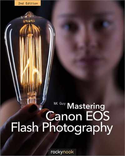
In short, the limits imposed by the inverse square law explain the differences in lighting between foreground and background in a typical flash-illuminated photograph. A flash unit needs four times the power output in order to throw light twice as far.
KEY POINT
Light decreases very rapidly with increased distance from its source, in accordance with the inverse square law. This is why it’s easier to illuminate a nearby object with flash than an object slightly farther away.
7.43 Light is projected along a wall and reflected off the model’s face. Note how rapidly the light falls off in brightness, especially the pinkish light reflected off her face, which also isn’t as sharply focused as the bluer light from the flash unit.
7.15Guide numbers
The maximum distance range of a portable flash unit is often described by its guide number (GN). Users of automatic flash metering may never deal with guide numbers at all, but they can be used to calculate the aperture required to illuminate a subject at a certain distance, or vice-versa. The GN describes the distance coverage of a flash unit, not its power output, which is important when comparing different flash units.
To find the aperture (f-stop number) required, divide the unit’s guide number by the distance to the subject. To find the maximum distance that can be reasonably illuminated using the current aperture, divide the GN number by the f-stop. In each case, the distance from the flash unit to the subject is important, not the distance from the camera to the subject. These two distances may be the same with on-camera flash, but not with off-camera flash or with bounce flash.
f-stop number = GN/distance
distance = GN/f-stop number
A guide number is only useful if the distance units and the sensitivity of the film or sensor are known. Canon provides guide numbers in meters for ISO 100. The Speedlite product names, such as 600EX, include the highest metric guide number of the flash unit (the guide number on maximum zoom in the case of zooming flash units) multiplied by 10.
Older Canon USA literature uses guide numbers in feet, though newer documents list both feet and meters. The former can be confusing: a flash unit of GN 43 sounds great, but not if it’s actually a metric GN 13. Only metric guide numbers are used in this book to be consistent with the Speedlite naming system. To convert to a GN in feet, simply multiply the metric GN by 3.

7.44 Old flash units, like this Vivitar 285 from the 1970s, sometimes had a daunting calculator on the side. You could dial in the film speed in ISO, the lens aperture as an f-stop number, and the distance in feet or meters. It would then tell you a color-coded power output setting. Canon Ext.M autoflash mode does something similar today.
Remember that the GN takes film / sensor sensitivity into account, since flash range increases with ISO. So if an ISO / film speed other than ISO 100 is used, that must be factored in. The math is based on the inverse square law: quadruple the ISO to double the guide number. Here’s a quick conversion method that avoids square roots:
ISO doubles: GN × 1.4
ISO halves: GN × 0.7
Another critical point when comparing flash units is that zooming flash heads affect the GN. For example, two units may have identical power circuits and flash tubes, but one has a zooming head that goes to 105mm whereas the other goes to 80mm. The former unit will have a higher maximum guide number, since it can concentrate its beam of light farther. Studio units with interchangeable reflectors have similar issues.
Finally, a fair bit of subjectivity goes into determining the guide number. After all, how is an “adequately exposed” subject determined? Guide numbers are not a reliable way to compare flash units built by different manufacturers. Companies tend to be somewhat optimistic when it comes to assigning guide numbers to their products.
7.16Quantifying flash output
One challenging aspect of comparing flash products from different companies is that each firm measures output differently. There’s no one standard, so it’s virtually impossible to know whether one company’s flash unit puts out more light than another’s without performing empirical tests with a meter.
A fundamental problem is that each company measures a different thing. They’re not necessarily being dishonest; measuring light is a complicated subject. Consider ordinary household lighting. Years ago, when tungsten bulbs were the only household electric light source available, people got into the habit of referring to the brightness of a bulb by its wattage. Everyone knew how much light a 60-watt bulb produced. Unfortunately, wattage refers to the electricity consumed by the bulb, not the amount of light produced by it. So this simple system fell apart when fluorescent bulbs and LEDs arrived on the scene. All of a sudden there were more efficient bulbs that produced the same amount of light but at a lower wattage.
The other major issue involves area and distance. Think of a regular bulb in a ceiling fixture. It spreads light evenly and gently around the room. But what if the same bulb were in a desk lamp? All of a sudden its light would seem very intense and narrowed down. The same amount of light is produced; it’s just more concentrated by the lamp’s reflector.
These two issues affect measuring systems used by flash units as well, with the added complication that flash involves brief pulses of light, not continuous streams.
7.16.1Watt-seconds (Joules)
The two terms are synonymous, and they are a measure of the amount of energy produced by a device’s electrical system; they are not an indication of light output. This is a common measurement, but unfortunately not always a useful one. A highly efficient electronic design may consume fewer Joules than a badly designed one, yet put out as much light.
7.16.2Effective watt-seconds
A marketing variant on watt-seconds. A manufacturer may claim that its flash units are more efficient than another’s and thus produce as many “effective watt-seconds” as their competitor’s products. Nobody really knows what this means: it’s very effective confusing advertising!
7.16.3Guide number
A measurement of flash coverage described above. The key point is that the guide number is highly dependent on the coverage of the flash head, not just the light output of the flash tube. This measurement also takes film sensitivity / ISO into account.
7.16.4Lumen-seconds
A metric measurement of the amount of light (the “luminous flux”), weighted to the sensitivity of the human eye, produced by a light source for a period of one second. Unfortunately, discussions of lumens veer off rapidly into the arcane provinces of physicists and engineers. (The official definition of the lumen involves concepts such as solid angles of steradians and single-frequency 540 terahertz lights.) Nonetheless, it is a proper and honest way of evaluating the amount of light produced by a device, though not one commonly used by flash unit manufacturers.
7.16.5Beam candlepower seconds (BCPS)
A measurement of the intensity of a light source, taking the qualities of a reflector or a lens into account (i.e., the “beam”).
7.17Exposure value (EV)
The sensitivity of camera gear at autofocusing or determining correct exposure metering is rated in terms of EV—exposure value—for a given lens type and film speed or digital ISO.
Since the amount of light hitting the film or sensor is determined by exposure time (shutter speed) and lens aperture, EVs are simply combinations of shutter speeds and apertures that produce the same exposures. For example:
f/4 at 1/30 sec has an EV of 9
f/2 at 1/125 sec has an EV of 9
Both of these speed / aperture combinations let the same amount of light hit the film or sensor; the only differences between the two are depth of field and type of motion recorded. Depth of field decreases as the aperture increases, and subject motion blur increases as shutter speed decreases.
However, it’s only meaningful to compare exposure values if they’re rated for the same film speed or ISO. Canon rates EV values in its documentation for a standard 50mm f1.4 lens using ISO 100.
Table 7.1: Exposure value (EV) table at ISO 100

The vertical axis shows shutter speed (Tv or time value) in seconds. The horizontal axis shows the lens aperture (Av or aperture value) in f-stops. EV tables makes it easy to work out specific combinations of shutter speed and aperture for different light levels. They were popular decades ago, before automatic light meters were built into each camera. EV tables are still used today by night photographers. Note that this particular table is for ISO 100 only. For other ISO values you’ll need to increase the EV by 1 for each doubling of the ISO. Thus EV 9 at ISO 100 would be EV 10 at ISO 200 and EV 11 at ISO 400.
7.18Color and shades of white
When it comes to interpreting color, our eyes (or, more accurately, our brains) are extremely adaptable. A sheet of white paper in a room lit by an incandescent tungsten bulb will look pure white. The same sheet of paper carried outdoors and examined in sunlight will still look white. But to a machine, the light reflected off the paper will look completely different. Tungsten bulbs and the sun produce different colors of light: tungsten light is fairly orange whereas sunlight is relatively blue.
Normally, our visual systems compensate for these differences in color temperature automatically. One of the few times they become really noticeable is when encountering different types of light at dusk.
Take the classic scene at right. The incandescent light spilling from the windows of the old mill looks quite orange-yellow in tone compared to the blue of the evening sky.
In colloquial English, we say that yellowish or reddish light is “warmer” than bluish light. Yet according to a physicist or a photographer, bluer light has a higher color temperature than reddish light. Why is this, and what does this mean?

7.45 Cropthorne Mill on the River Avon. Near Evesham, Worcestershire, England.
7.18.1Color temperature
Color temperature is a scientific model that explains certain aspects of the concept of “white.” Imagine a plain iron bar. At room temperature, it may appear almost black. But, when heated, it will start to glow with a dull red light. As it gets heated further, the light becomes yellow and eventually white as it melts.
This is the basis of color temperature. Instead of a lump of iron, the model relies on a theoretical notion: a “black body,” or an imaginary substance that absorbs all light and is, therefore, black to the eye. As it’s heated, this black body will start to radiate energy that we can see as light. The color of the light is described in terms of the temperature required to create it, measured in Kelvin units. (Kelvin is similar to the Celsius scale but uses absolute zero, −273.15°C, as the starting point rather than the freezing temperature of water.)
Regular incandescent light has a theoretical color temperature of about 3200 Kelvin, though this varies and household bulbs often produce about 2900K. They also drop in color temperature as they age or when put on a dimmer circuit. Tungsten halogen bulbs (usually just called “halogens”) and non-daylight-corrected photoflood bulbs are usually slightly higher, sometimes reaching 3400K. The light from a candle flame is quite low in temperature, hovering around 1400–2000K.

7.46 This photo is lit primarily by candles, which lend a characteristic reddish-orange glow. A tungsten light bulb was used to fill in the shadows, since its yellow light blends quite well. Edward Saperia demonstrates Cryptofloricon.com, his online messaging service that sends encoded communiqués through flowers.
Daylight is between 5000K and 6000K, often given as 5500K for the temperate midday sun. Naturally these values can differ depending on time of the day, latitudes and altitudes, and weather conditions. In fact, natural light can vary from around 2000K at sunset to over 20,000K in blue evening shade. Skylight, or the sun’s light scattered by the atmosphere, is extremely blue in color. ![]() 7.47
7.47

7.47
It’s important to remember that the Kelvin color temperature value doesn’t necessarily refer to the actual physical temperature of an object. This description of color temperature is also a vast oversimplification of physical theory, but one that’s useful to us as photographers.
KEY POINT
You can think of color temperature as a way of quantifying, or conveniently labeling, shades of white on a linear orange to blue spectrum.

7.48 This available light photo, taken at the Alhambra in Granada, Spain, shows the tremendous difference between the tungsten-lit interior (most of the image) and the daylight shining in from outside (the seemingly blue arch). The stonework is all the same color, but it’s lit by light sources with different color temperatures.
7.18.2Color temperature and film
Color temperature isn’t some academic issue. It’s a real issue when shooting with color film because film records light using chemical processes and can’t adapt to changing light conditions. Film is formulated in the factory to assume a certain color temperature is white.
This is what is meant by “daylight” film and “tungsten” film—they’re film types designed to assume that daylight and regular tungsten light bulbs, respectively, are white. Color shifts will occur if the wrong type of film is used. A tungsten-lit room shot on daylight film will look quite orange, and a daylight-lit room shot on tungsten film will look quite blue. So it’s important to use film that matches the lighting conditions, or use appropriate filters. ![]() 7.48
7.48
However, there are very few film emulsions still available that are tungsten-balanced, and most are very slow. If you need a high-speed film for tungsten lighting (e.g., you’re shooting in a dark theater), then you either have to use color-correcting filters or shoot digital. ![]() 7.49
7.49

7.49
7.18.3Color temperature and digital
Color temperature is more of an opportunity than a problem in the world of digital. Digital cameras record color as a bunch of numbers in a computer, rather than on a physical material with complex chemical interactions. So it’s pretty easy for a digital camera to assume different colors are the correct white point. This can easily be used to creatively alter, as well as simply correct, mismatches in lighting color.
Digital white balance (WB) offers a number of choices. A camera can operate in automatic mode (AWB), or you can specify different preset or custom white balance settings as required. In AWB mode, the camera examines the recorded scene and decides the dominant color cast, at least between 3000K and 7000K. (Two early EOS digitals, the 1D and the 1Ds, also used an external white balance sensor.) Preset color balance settings make certain assumptions about color conditions, such as daylight, flash, cloudy skies, and so on. And custom white balance settings allow you to take a picture of a white object lit by ambient light so that the camera can measure white balance against that.

7.50 White balance settings

7.51
EOS digital bodies with a “flash” white balance setting assume a color temperature of 6000K in order to match the light from common studio flash units. However, Speedlite flash units are closer to a daylight color temperature (at 5500K or so), so a photo lit with a Speedlite and the flash white balance setting can end up being a little off. Automatic white balance (AWB) or daylight white balance might be better options. Alternatively, a custom white balance setting can be used, especially user-defined custom white balance.

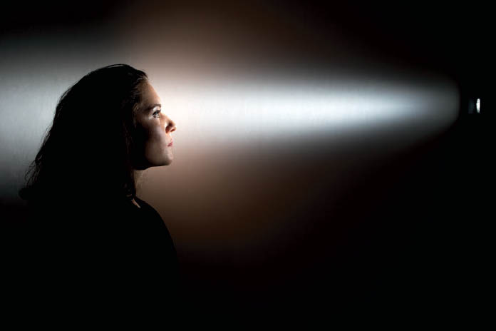
7.52 This photo shows how a camera’s automatic white balance system can have problems. The camera assumed that the orange glow from the “squirrel cage” tungsten light bulb is the dominant light source and balanced for that accordingly. The bulb, driven at half power, is producing very orange light compared to the two Elinchrom D-Lite studio units (equipped with narrow striplights to get the striped effect on the bulb) actually lighting the scene. The final result is that the white balance of the model’s face is far too blue.

7.53 This version was manually white balanced to restore the proper warm color to the model’s face. This also heightened the orange of the bulb’s filaments, but that isn’t really a problem for this shot. EOS 5D Mark II, 1/10 sec at f/5.6, ISO 50, 100mm.
Finally, digital white balance is actually more complex than this. Instead of simply representing color on a single yellow-blue axis, white balance also uses a magenta-green axis. The color temperature scale is just the one we encounter in everyday life more regularly, owing to the way common light sources work. ![]() 7.54
7.54

7.54
7.19Color filters
The light from a portable flash unit is pretty close to direct noonday sun in a temperate latitude: around 5500K to 5600K, or a slightly bluish-white light. But this type of simulated daylight isn’t going to be the right white for every photograph. Daylight may be too warm or cool, and it may clash with existing light. Or perhaps a dramatic color, such as a rich red or dark blue, is needed for a special effect. This is one area where color filters come in.
White light consists of colors of various wavelengths across the whole color spectrum, as Newton discovered with his famous prism experiments. Our brains interpret this sensation of light energy as something we call “white.” Since white light is made up of so many wavelengths of energy, it’s easy to put some material in front of a light source that will block or absorb certain frequencies. Our brains then interpret the remaining wavelengths of light as a different, non-white color.
Color filters for light sources typically serve one of two purposes. First, they are commonly used for color correction, which usually means altering the color temperature of white light for color matching. Second, they are used to produce specific strong colors for special effects.

7.55 The 1980s called, and they want their filters back. This shot was backlit by an unfiltered Bowens Gemini monolight, with the foreground fill by a 580EX II in manual mode, zoomed to 105mm and filtered with a red gel.
Filters can be put in different places. To change the color of an entire scene, a filter can, of course, be placed over the lens. To affect the output of a specific lamp, a flexible gel filter can be put over that specific light. A filter or colored diffuser can be put over a flash unit’s head to affect just the light it produces.
7.19.1Color temperature correction
Since the light from a flash unit is a neutral to bluish white, it can easily be tinted. It might be necessary to balance the light from a flash unit to match ambient lighting conditions. The most common need is found indoors where you often need a flash unit to match the yellowish light from a tungsten light bulb. Another common use is to “warm up” a flash to more closely match sunshine at dawn or sunset. If filters aren’t used in cases like this you can get the colors of different areas in a photo clashing unnaturally.
The converse can also be true. Maybe you want flash-lit areas to be a dramatically different in color from the ambient lighting for creative effect. Color temperature conversion can go in one of two ways. To go from yellow-orange light (tungsten) to blue light (daylight), a “cooling” or blue filter is required. To go the other way, a “warming” or yellow-amber filter is needed. As noted earlier, these names are somewhat confusing since cooling involves an increase in color temperature and vice-versa. The names reflect ordinary casual usage of the words and not color temperature theory.

7.56 The lower right side of this photo is poorly lit and quite dark. This is a shame, since it’s the original Roman section of the Roman baths in Bath, England. The Victorian reconstruction is well lit with artificial lighting. Fill flash can help in this regard, but light from a normal flash would be too blue in color.

7.57 This shot has some fill from a Speedlite 580EX II. A warming filter was used so that the light from the flash unit would approximate the orange-yellow artificial lighting.
7.19.2Non-tungsten artificial lighting
Color casts also occur from other forms of artificial lighting. The light from fluorescent tubes can often veer off into a nasty green. Full-spectrum fluorescent bulbs have a slightly more pleasing color balance, though they don’t quite match incandescent lights. The color output of fluorescents tends to “spike,” or produce slightly more intense colors in narrow bands. This is one reason fluorescent light, even from compact fluorescents designed to simulate tungsten, can look unnatural.
To minimize fluorescent color casts, many news photographers carry pale green filters. These help flash units to more closely match the unhealthy greenish glow of an office. When shooting digital, the camera is then set to fluorescent white balance, and the result should be more consistent color in the final photo.
More problematic are the high-pressure mercury lamps used for industrial/public space lighting and the yellow sodium lamps used for streetlights. These gas-discharge sources produce light in very narrow bands, resulting in unpredictable color casts that depend on the formulation of the bulbs. Complicating matters is that such discontinuous light sources don’t glow but flash on and off 50 or 60 times per second. This imperceptible pulsing is why photos taken with short shutter speeds may have inconsistent exposure or color if the picture happens to be taken at a low point or high point of the lamp’s power cycle. ![]() 7.58
7.58
Technically speaking, the term “color temperature” shouldn’t be used for fluorescent and gas-discharge lights, since they don’t have incandescent filaments. However, approximate equivalent color temperature numbers (correlated color temperature values) are often supplied by manufacturers as a convenience.

7.58 Like many public spaces, the Piazza San Marco in Venice is lit by high-efficiency, gas-discharge lights. Building interiors are lit by tungsten and fluorescent sources. These artificial lights look very yellow and orange against the blue twilight sky.
7.19.3Mixed light sources
Shooting in mixed lighting conditions can be very challenging without some filtration. The colors in the final photo will be all over the map, and it can be difficult or impossible to fix digitally after the fact. Color correction filters to modify the light output of a flash can tame more extreme color differences.
Short of switching to black and white, the easiest way of dealing with mixed lighting sources is to gel any lights under your control to match the dominant ambient light. You can never get every light source to match precisely; the goal should be to minimize gross or obtrusive color differences. For example, a room lit with tungsten light would clash with unfiltered fill flash. The simple addition of a half-strength yellow (1/2 CTO: see 7.19.5) filter on the flash head could be enough to bring the fill close enough in line to the ambient artificial light (full CTO filters can be too yellow). ![]() 7.59
7.59
With that in mind, there’s still something to be said for emphasizing various color sources. Take the photo that opens this chapter, for example. Lyle Rowell’s LRRY, a walking kinetic sculpture powered by a car engine, was lit by three basic light sources. The first was a snooted studio flash unit to camera left for fill. Directly behind the sculpture, illuminating the smoke with bluish-white flash, was a high-powered studio unit. And the intense light from the propane flames bathed the front of the sculpture in yellow light. The different colors of light created a far more interesting and layered shot than if all the light sources had been the same color.

7.59 This photo is lit by two light sources. One is an AlienBees B1600 flash unit, powered by a generator, located camera right. The other is the stream of flame itself. The result is two different shadows of two different colors. This shot was adjusted digitally to make the flash-illuminated areas slightly warmer, but this resulted in a rather orange patch of ground lit by the flame.

7.60 Speedlite 600EX/600EX-RT units ship with clip-on filter holders and CTO filters.
7.19.4Special effect filters
Filters are available in almost every color imaginable, from subtle to lurid. Simply by installing a filter over a light, a white backdrop can be changed to blue or green. A red filter can simulate neon lighting coming through the window of a motel room. But note that filters have to be darker (i.e., more saturated) than one might expect to achieve rich colors, particularly with bright flash units and other high-powered light sources. A red-filtered light might end up looking rather pinkish in the final photo. ![]() 7.61
7.61
7.19.5Filter naming
Filters used for changing the color of light sources all have manufacturer-specific codes or names. However, gels for color temperature conversions are often described as “color temperature orange/CTO” or “color temperature blue/CTB” depending on whether they’re warming or cooling filters. Less saturated versions of these filters are usually named in fractions, such as 1/2 CTO or 1/4 CTB. Stacking a pair of 1/2 CTO filters will yield the same color as a single full CTO, for example.
Note that a CTO from one maker will not have precisely the same color as a CTO from another—there are always slight differences. A CTO variant that a lot of photographers find useful is “color temperature straw/CTS,” which has similar color temperature shifting properties to CTO but with a less reddish tone.
7.61 This picture was taken using three Speedlites. A 580EX on-camera was used for white light fill and as an E-TTL master. A 580EX II was on a tall light stand, camera left, and filtered red. A 430EX II was on a lower light stand, camera right, and filtered.
Table 7.2: Yellow-orange “warming” filters

Table 7.3: Blue “cooling” filters

Some manufacturers of lens filters use the Wratten series of numbers. More than a century ago, British inventor Frederick Wratten developed a fairly arbitrarily numbered series of color filters. Kodak bought Wratten’s company in 1912, though Wratten-branded filters are now sold by Tiffen. Orange-colored Wratten filters are in the 85 series, and blue-colored Wratten filters are in the 80 series. German manufacturers use a different system in which KB is a cooling (blue) filter and KR is a warming (orange) filter.
Filters for special effects do not have any sort of standardized names. They tend to have cheesy names like paint colors, of the “moonlight blue,” “neon carrot,” and “exploded strawberry pink” variety.

7.62 Some common filter colors. The colors are full, 1/2, 1/4, and 1/8 CTO (left) and CTB (right).
7.19.6Limitations of filters
One important thing to remember about filters is that they cannot shift colors along the spectrum, per se. All a filter does is simply prevent certain wavelengths of light from passing through by absorbing them. So, by definition, color-correction filters always reduce the amount of light entering the camera or produced by a light source. Blue or red filters in particular can easily cost you a stop of light.
As discussed above, filters change the color of white light by removing certain wavelengths, so filtering a flash head or tungsten bulb works well. But if a scene is illuminated by, say, pure red light, then it isn’t possible to apply any sort of filter on a lens to make things a different color. Filters can’t add light of any wavelengths or convert incoming light to a different wavelength.
This is why filters are fairly useless when you’ve got light sources such as yellow-orange sodium streetlights, neon signs, mercury vapor gymnasium/industrial lighting, or color LEDs. These lamps produce light of very narrow spectral bands, so filtering out the dominant color doesn’t leave much else.
The limits of filtration really hit film users when it comes to color correction. There are ways of altering colors in the darkroom, but they’re expensive and cumbersome. By contrast, color mismatches are a mere inconvenience for digital users. The only complication is when numerous light sources of different colors illuminate a scene, because different colored patches of light will show in the final image.

7.63 This diagram shows how a filter blocks (absorbs) light of certain colors. In this exaggerated example, white light consisting of every visible wavelength is shone onto a filter. The filter blocks the passage of blue and green wavelengths of light, allowing only reds to pass through. The filter can’t transform blue light into red light or anything like that.
7.20Infrared (IR)
From a non-technical perspective, infrared (IR) can be thought of as invisible light used by devices such as TV remote controls and night vision cameras. From a technical perspective, IR refers to a band of electromagnetic radiation that is just outside the range of human visual perception. The word stems from the Latin “infra,” for “below”; in this case, the light is below the red section of the light spectrum in terms of frequency.
Contrary to popular misconception, IR-sensitive cameras don’t record heat: they aren’t thermal imagers. Infrared photography records reflected IR from an IR source such as the sun. Ordinary xenon flash tubes are also an excellent source of IR, and cameras or film capable of sensing IR can easily be used with flash. This fact can be exploited for flash photography in which the subjects can’t see the flash.
For example, 1940s American news photographer Weegee (Arthur Fellig) sneakily took a series of famously voyeuristic photographs of people watching movies and making out in theaters. They were shot using infraredsensitive film and a flash filtered to pass IR and block visible light, so that the subjects didn’t know they had been photographed. The ethics of this type of photography are perhaps best discussed elsewhere.

7.64 The LED on an IR remote control is invisible to the human eye, but is clearly recorded by a camera that’s capable of seeing into the infrared.

7.65 Digital Voyeurvision! This picture was taken in near-complete darkness. The scene was lit by an on-camera flash unit with infrared filtration, and the camera was a digital EOS 10D modified to record IR but not visible light.
True infrared-sensitive film is available from professional suppliers, and most digital cameras have IR-blocking filters installed over their image sensors. However, many digital cameras can be modified by removing these filters, making them sensitive to a range of IR energy.
Flash tubes also produce ultraviolet (UV) energy at the other end of the spectrum. This is much more difficult to use photographically, however, since it requires lenses manufactured from crystal or special UV-passing glass. In addition, most flash units have treated glass to reduce their UV output, since UV adversely affects visible-light photography. Some Pyrex domes (section 13.2.1) are also coated to block UV.

7.66 The mysterious world of infrared portraiture. The left-hand photo was taken with a EOS 5D, which records ordinary visible light. The right-hand photo was taken with a modified 10D that had a light-blocking IR-passing filter over the lens. In both shots, a single Elinchrom D-Lite 4 monolight was used.
Note how light-absorbing areas of the photo, such as dark brown irises and black synthetic fabric, actually tend to reflect infrared. Skin takes on a strange alabaster-like look, and veins suddenly become quite visible, a characteristic helpful to medical researchers and forensics investigators.
7.21EXIF and flash data
One of the great hidden benefits of digital cameras, from a learning perspective, is that they automatically label each photo with shooting data in EXIF (Exchangeable Image File) format. This makes it easy to go back after a shoot and see exactly what shutter speed, aperture, focal length, etc. was used. This is far more convenient than jotting down information in a notebook while shooting photos.
Some flash-related data is stored as well. EOS cameras record where flash is fired or not, whether flash exposure compensation is applied, what the FEC value is, and whether redeye reduction is enabled. Note that this data is stored only if a fully automatic Speedlite flash unit (or popup flash) is used: the camera has no way of knowing if a manual external flash unit is fired. Unfortunately, wireless E-TTL settings are not recorded in EXIF.
To view EXIF information, open an image using Canon’s Digital Photo Professional software, or any other photo-editing application such as Adobe Photoshop that can display EXIF metadata. ![]() 7.67
7.67

7.67

7.68 Like a Japanese manga comic, the 600EX will show this steaming icon if it overheats.
7.22Safety and physical properties
7.22.1Overheating and fire hazards
A flash unit generates a surprising amount of heat when fired. Even a battery-powered flash unit can burn you if the flash head is held to your skin. Normally the heat dissipates rapidly, since the flash burst is so brief. But in a rapid-fire situation, the heat can accumulate quite quickly, risking damage to the flash tube, its clear plastic cover, or anything touching it. A flash tube can actually scorch or ignite cloth or paper.
Heavily used older battery flash units often have a yellow or orange patch in the middle of the plastic flash lens. This occurs when using high-powered flashes repeatedly (e.g., wedding photography) or when using high-speed sync or modeling flash for extended periods. Filters or other accessories over the flash head can increase the risk of overheating as well.
To minimize the risk of damage, many flash units from Nikon SB900s to Elinchrom D-Lites contain temperature sensors that shut off the unit if it becomes too hot. The unit must then be left to cool down. The Speedlite 580EX II has such a temperature sensor and also counts the number of shots fired within a specific time frame. It then forces an increased wait time between firings, though there’s no way to override this. The 600EX/600EX-RT’s display will switch to a bright red backlight to warn you if it’s overheating. Some EOS cameras with built-in flash units also restrict firings for safety reasons. If a camera displays the message BUSY and refuses to fire the flash unit for a few seconds, this is why.
Because it’s incredibly annoying when a flash unit simply goes on strike like this for some period of time, it’s worth testing the heat sensitivity of your gear before doing an important shoot.
Another significant fire risk is posed by the incandescent bulbs used as modeling lights in AC-powered studio gear. These can start a fire in moments if they touch fabric or plastic, such as a softbox or other diffuser. ![]() 7.69
7.69
Some high-powered studio units have optional glass domes (section 13.2.1) that can be installed over the flash tube and modeling lamp to protect both.
7.22.2Flash safety and babies
A common concern is whether flash photography can damage the sensitive eyes of babies and infants. I put the question to the Pediatric Service of the Moorfields Eye Hospital in London, and they confirmed that they were not aware of any serious dangers from occasional use of flash at normal distances from the eye.
Having said that, this is obviously not a free license to blast a poor baby with flash. At the very least, the baby is probably going to find it an unpleasant experience. This also doesn’t apply to firing a flash close to a baby’s face (which is something that should never be done to anybody) and which sometimes happens because babies are so small and a common tendency is to put the camera close to them.
In short, taking the odd flash photo in a room that happens to have a baby in it is unlikely to cause any problems for the baby’s vision. But enforcing flash safety measures is a good way to keep Uncle Bob from sticking his flash-equipped point-and-shoot into the baby’s face. And frankly, baby photos are probably going to benefit from soft natural light rather than harsh on-camera flash anyway.

7.69 The risk of fire is not hypothetical. This high wattage bulb touched the side of a light diffuser for a few seconds with incendiary results.

7.70 This photo of a baby’s delicate eyes was taken with daylight fill flash. To reduce any possible discomfort, the flash was positioned some distance from the baby, and shone into a Rogue Flash-Bender reflector, rather than being aimed directly at the baby’s face.
7.22.3Shock hazards
Electronic flash technology involves extremely high voltages—literally hundreds of volts. The internal components of any flash unit maintain a high-voltage kick even when the device is turned off. It takes quite a while for this high-voltage energy to drain out of a flash unit’s capacitors. Even cheap disposable cameras with built-in flash units can produce severe shocks if they’re disassembled.
For this reason, it’s very important that an electronic flash unit, whether powered by small batteries or AC power, never be opened up except by an experienced technician ![]() 7.71. The capacitors might literally give a nasty shock, which could be deadly to those with susceptible heart conditions. It’s also essential to never expose a flash unit to moisture or liquids.
7.71. The capacitors might literally give a nasty shock, which could be deadly to those with susceptible heart conditions. It’s also essential to never expose a flash unit to moisture or liquids.

7.71 Don’t try this at home. Really. This is the interior of a high-powered studio flash unit. The large black cylinders are huge capacitors, capable of storing lethal amounts of power.
7.22.4Noise
Flash units always produce sound. Battery units usually emit a high-pitched whistle that increases in frequency as the unit is charged up, caused by an oscillator that converts DC to the high AC voltages needed to charge the capacitor. Some units, like the 540EZ/550EX, have multiplexers that make a noise when idling. More recent EX models, such as the 580EX II, have deliberately high-frequency charging circuits so they’re inaudible to the human ear.
Zooming units make a rattling buzz when the flash tube moves inside the head. Finally, all flash units make a soft popping sound when fired.
The 600EX/600EX-RT are the first Speedlites to contain beepers, which can be very useful for wireless flash setups. They’re annoying, but they provide instant feedback that a remote flash unit is charged and ready to fire. ![]() 7.72
7.72

7.72 Custom function 20 on the Speedlite 600EX/600EX-RT controls the beeper.
7.22.5Counterfeits
This may sound like a surprising problem, but there have been fake Canon Speedlites hitting the market for a few years now. Externally, they closely resemble high-end Canon gear such as the 580EX II or 600EX-RT, and may even have the Canon logo printed on them. But they’re actually inferior copies, missing many key features such as high-speed sync and radio wireless. They may also lack proper safety functions. Another trick used to catch the unwary is to sell a bare-bones all-manual flash unit in a plastic casing that’s an exact copy of a Canon Speedlite unit.
Be suspicious of too-good-to-be-true deals on online auction sites, as they may well be too good to be true! Buying from reputable dealers may cost a little more in the short term, but at least you know you’ve got somewhere to go back to if you do end up with an inferior product.