
9 Canon Speedlites
The Whole Family. A representative of every E-series Canon Speedlite produced between 1986 and 2009.
Canon Speedlites are compact, battery-powered, automatic flash units sold by Canon since the 1970s. And this is a comprehensive and exhaustive (if not exhausting) list of the features offered by post-1987 Speedlites that are compatible with EOS cameras. Not every model has every function, of course. Check the table in appendix C for details.

9.1 Key parts of a Speedlite 580EX II flash unit
9.1Hotshoes
Hotshoes are the traditional, square shaped slide-in sockets on the top of all EOS cameras, and indeed most SLRs sold today. Despite the dramatic name, hotshoes carry no risk of electrocution and don’t get warm. “Hot” is just slang for their electrical connectors, though non-electrical accessories such as bubble levels and flash diffusers can also be mounted on them.

9.2 Black painted metal hotshoe
The earliest hotshoes from the 1940s had a single electrical contact in the middle that carried the synchronization signal. The metal frame served as an electrical ground; a design still used today. EOS cameras have four additional small contacts arranged behind the main stud. These carry computer instructions, supporting advanced features such as flash metering and flash head zooming. The signals sent by these four contacts are unique to Canon—each modern camera manufacturer uses its own pin arrangement and camera/flash communications system.

9.3 Unpainted metal hotshoe
For a while, Canon painted hotshoe frames black, which looks great out of the box. However, the paint tended to scratch and flake off, sometimes insulating the connectors, so EOS bodies now have unpainted metal shoes.
Hotshoes are something of a weak link in the chain of any flash system. They were initially designed over half a century ago for small devices (“cold” accessory shoes were simply brackets with no electrical connectors) and have been modified over the years by different manufacturers to accept increasingly large flash units. Nearly all makers, with the exception of Sony/Minolta, use the same basic hotshoe design, though with different contact configurations.
9.1.1Flash feet
The base of a flash unit that fastens to a hotshoe is known, logically enough, as its foot. Over the years Canon has used five basic types.
The oldest models are plastic, with rotating pressure rings to clamp the flash down. The tightening direction is usually marked with an arrow, and sometimes with “L” for lock. The main drawback of these feet is that the rings can occasionally bind, making it difficult to remove the flash unit. In such cases, try tightening slightly, then firmly untightening the ring.

9.4 Flash foot with collar and pin
Later feet have pressure rings with a small retractable pin at the front. This pin lowers into a matching hole in the shoe, helping it lock in place. The pin is spring-loaded, so the flash will still fit in hotshoes that lack the locking pin hole.
Larger and more recent Speedlites have a metal latching foot. Billed as sturdier than the plastic design, there may also be a rubber shroud which matches the gasket on weatherproofed cameras, minimizing water and dust penetration. (See section 9.34 on weatherproofing.) Instead of a ring, there’s a quick-release latch. Turn the latch one way to lock it; press the release button and turn it the other way to unlock it. ![]() 9.5
9.5

9.5 Flash foot with collar and pin
These newer latches are easy to operate, but they don’t always tighten as firmly as the pressure ring design, especially if the camera is held sideways in portrait configuration. If this occurs, inconsistent contact with the connectors may result. A flash unit might, for example, suddenly switch from E-TTL mode to TTL if it loses communication with the camera. On a digital body, this can mean the flash unit fires at full power or not at all. ![]() 9.6
9.6

9.6 Flash foot with quick release
In 2012, Canon introduced a variation on this design for its high-end flash units: a mechanism slides the electrical pins first one way and then the other as the tightening lever is moved. This is marketed as a “self-cleaning” mechanism, since the motion hopefully will dislodge debris. ![]() 9.7
9.7

9.7 Self-cleaning foot mechanism.
Finally, tiny inexpensive flash units have simple sliding latches. ![]() 9.8
9.8

9.8 Foot with latch
If a flash fails to fire reliably, the first things to check are the flash foot and camera hotshoe. The contacts may require gentle cleaning, or the screws holding in the shoe might need tightening. Never use anything more than a soft cloth to clean the contacts, though a drop of deoxidizing contact cleaner can help. Pencil erasers and emery cloths are abrasive and will permanently damage the contacts over time.
Note that it’s a bad idea to lift a joined camera and flash unit by the flash unit, as this puts a lot of strain on the foot and shoe. Pick up the camera body to reduce the risk of damage!
9.2Flash heads
In keeping with the body metaphor, the part of the flash unit with the light-producing flash tube is called its head. The tube is mounted inside a small reflector and covered with a protective plastic lens. The lens is molded in a Fresnel-type pattern to concentrate the light output. There’s sometimes a slightly yellowish tint to the plastic to help make the flash-produced light slightly less blue. ![]() 9.9
9.9

9.9
9.3LCDs
Higher-end Speedlite flash units, including all the 500–600 series models and most of the 400 series models, are equipped with liquid crystal display (LCD) panels. Until the introduction of dot matrix displays in 2012, each LCD had a specific set of symbols and numbers etched into it. LCDs have optional backlights for low-light operation, and are illuminated for a few seconds at the touch of a button.
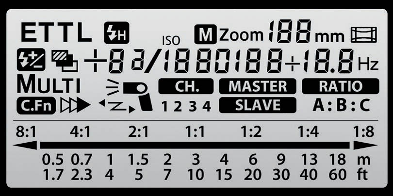
This is all the information that can be displayed on the LCD of a 580EX II unit, though of course it never actually looks like this at any one time. Panels of this type have specific areas used for the display of certain symbols or numbers. They’re sharp and crisp, but completely inflexible—they can only display the symbols etched into them. ![]() 9.10
9.10
9.10
9.3.1Dot-matrix LCDs
In 2012 Canon introduced three high-end units, the 600EX, 600EX-RT, and ST-E3-RT, which feature black and white dot-matrix displays. These were followed by the Macro Ring Light MR-14EX II and Speedlite 430EX III/430EX III-RT.
The panels on these units are the largest ever seen on a Speedlite, and of course they can display any graphic, icon, or text like any computer screen. Unfortunately, the display dot density is fairly low-rez at 172 × 104 pixels, so some symbols are a bit chunky, and reversed text is a little hard to read compared to the old-style LCDs. It would be nice if they had full-color displays like mobile phones, though black-and-white displays do have a better battery life. ![]() 9.11
9.11

9.11
The 600EX, 600EX-RT, ST-R3-RT, and MR-14EX II units also have a group of four function buttons immediately below the display. These buttons aren’t physically labeled and can change function based on the label that appears above them, making the new interface very flexible. These Speedlites therefore have contextual menu-based systems. The 430EX III/430EX III-RT units have an on-screen menu that is mostly navigated by the control wheel. ![]() 9.12
9.12

9.12
The new displays also mean that previously inscrutable numbered custom functions are displayed visually on the screen. No longer do you have to photocopy your flash unit’s user manual so you can look up what custom function number corresponds with what actual feature!
The LCD and the buttons are also backlit, and can be manually set to green or orange. The non-macro units can also automatically change color depending on whether they’re operating in master/non-wireless or wireless slave mode (very useful for getting remote flash set up at a quick glance), and can also light up red if they overheat.
9.4Swivel and tilt for bounce flash
Most Speedlites, with the exception of small pocket units, have flash heads that can be tilted and swiveled to point independently of the body. This lets you bounce light off large surfaces such as walls or ceilings. It also means the flash head can point one way while the front of the unit’s body, where the optical wireless sensor is located, can face back towards the camera. Tilting on non-macro units is usually adjustable from 0° (straight forward) to 90° (vertically upwards), with 500–600 series units allowing a 7° downwards tilt for slightly improved close-up photography. ![]() 9.13
9.13

9.13
Swiveling usually goes from 0° to 180° left, which is facing backwards. Right swivel is either 0° to 90° or 180°, depending on the model. There are click stops at various detent positions, and most units have spring-loaded tilt latches. Recent models conveniently use a single pushbutton latch to unlock both tilt and swivel. Some units with LCDs show a small icon indicating whether the head is tilted or not. ![]() 9.14
9.14

9.14
The ability of some Speedlites to know whether the flash head is in bounce mode is used by some cameras. When ISO is set to AUTO, some EOS bodies after the Rebel T1i/500D and 7D will increase the ISO if a flash unit in bounce mode is detected, compensating for the reduction in range. Low-end flash units lack tilt and swivel heads, but by simply attaching the flash unit to an Off-Camera Shoe Cord (section 11.5.1) you can point the flash in any direction you want. However, cheaper flash units are also low-power models, so this technique isn’t always useful.

9.15 While tilt and swivel are normally used for bounce flash, they have other creative uses as well. In this shot, the on-camera 580EX II was deliberately angled upwards to illuminate the model while keeping the lower half of the freight elevator dark and mysterious.
9.5Zooming flash heads
The area of a scene illuminated by a flash unit needs to match, or slightly exceed, the field of view of the lens in use. If you’ve got a wide-angle lens, but your flash unit doesn’t cover the full area, your photos will have a darkened periphery. ![]() 9.16
9.16

9.16
The converse can also occur. A flash unit that covers a wide area will waste a lot of light illuminating areas of a scene that aren’t captured by a longer lens. ![]() 9.17
9.17

9.17
To solve this problem many Speedlites have adjustable coverage areas, thanks to small motors that move the flash tube. The closer the tube is to the clear plastic Fresnel lens at the front, the wider the coverage angle, and vice versa. This is a “zooming” flash head.

9.18 The guts of a 580EX’s flash head, showing the stationary white plastic reflector on which the flash tube assembly slides. The flash tube, mounted inside a silver frame, is surprisingly small. Note that you should never open up a flash unit like this, as dangerously high voltages remain inside the device even when the power is switched off. There’s a serious shock hazard if the wrong part is touched!
Most units cover the range of 24–80mm or 24–105mm lenses, though the 600EX/600EX-RT goes to 200mm. The motors have several detented steps matching popular prime lens focal lengths, such as 24–28–35–50–70–80–105mm. Continuous zooming to arbitrary focal lengths is not supported.
A flash unit’s upper zoom limit doesn’t mean it’s incompatible with longer lenses: it just means that it can’t concentrate its light for more efficient coverage of a narrower area. The reverse is not true at the wider end. For example, a flash unit with 24mm coverage at the wide end will cause a vignetting effect (darkening of corners or edges) when used with a 17mm lens.
Generally speaking, only mid- to high-end flash units can zoom, as the heads have to be larger and longer to accommodate the mechanism. It’s also important to remember that a flash unit’s advertised maximum power output might actually be partly related to its longest zoom setting and not to the actual maximum light output of its flash tube.
9.5.1Automatic zooming
Speedlites with motorized heads can adjust zoom settings automatically to match the lens. Canon EF and EF-S lenses—and fully compatible third-party lenses—contain computer chips that send the current focal length to any EOS camera. Likewise, EOS bodies can communicate with compatible flash units that are either on the camera’s hotshoe or connected using a fully compatible cable. (Cables that carry sync signals only, such as PC cables, will not transmit automatic zoom position commands.)
When the shutter release of a connected compatible camera is pressed halfway, motorized Speedlites use the nearest zoom setting that’s equal to, or less than, the focal length of the lens. They automatically change motor positions with a little whirring buzz if the zoom position is changed within six seconds of the shutter button being half-pressed, or if the button is continuously held down in the halfway position.
This automatic zooming occurs whenever the flash head is pointing directly ahead. Speedlites typically default to a 50mm zoom setting when their flash heads are in bounce mode (i.e., tilted or rotated). If a non-EF lens is attached (an old fully manual lens attached to the camera using a lens adapter ring, for example), or if an EF lens isn’t fully locked onto the camera, then the camera has no way of knowing what the focal length is. It will then typically default to a 35 or 50mm zoom setting.
Wireless-capable units with zooming heads (section 11.8) automatically zoom to 24mm when in wireless slave mode.
9.5.2Manual zooming
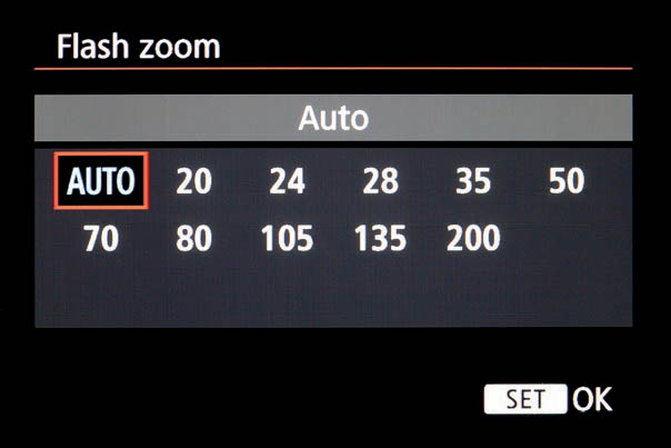
Most motorized flash units can override automatic zoom. This is typically done by pressing the button marked ZOOM. On the 600EX/600EX-RT, press function button 1 (Zm/C.Fn). On the 430EX III/430EX III-RT press the center ZOOM button then rotate the dial. On flash units with combined zoom/wireless buttons, use the control dial or +/– buttons to adjust the setting. On other flash units, press the ZOOM button repeatedly to cycle through the settings.

9.19
The focal length setting will go around, step by step, in a loop as it’s adjusted, accompanied by the buzz of the flash head motor. The letter M will appear next to the zoom setting if set manually. Some units also display A ZOOM if the unit is in automatic zoom mode. If the zoom setting displays – –, it means the flash head is tilted or swiveled in auto mode. (Zoom position can still be manually overridden.) If the lowest zoom setting possible blinks continuously on the LCD, then the current focal length of the lens is shorter than the flash unit’s widest coverage.
Cameras with menu control over compatible Speedlites can also adjust zoom settings via a menu option.
9.20
Some inexpensive models such as the 270EX and 320EX lack motors altogether. Their zoom heads must be slid back and forth by hand.
9.5.3Creative zooming
While adjustable flash coverage is intended to increase light efficiency when using longer lenses, it’s also a useful creative tool. A flash head can be deliberately zoomed out to a longer focal length to concentrate the light. This lets the flash unit work like a sort of soft-edged spotlight, sending pools of light to specific areas. In a sense, the flash unit behaves a bit like it would if a snoot or other light-restricting device were installed. Adjusting zoom coverage is also useful for ensuring that a flash unit’s light fills an umbrella or reflector.

9.21
Consequently, zooming heads with manual control are a particularly useful feature for a flash unit that’s used off-camera. Each slave unit can have its coverage angle set independently.

9.22 This performance photograph was lit primarily by available lighting—a pair of stage spotlights. But for added drama, a Speedlite 580EX was positioned behind the performers on a Manfrotto nano stand. The head was zoomed out to 105mm in order to create a narrow beam, providing a backlit spot effect.
9.5.4Zoom compensation
Camera bodies with image areas smaller than 35mm film (APS film cameras and most EOS digital cameras) don’t require as much area illumination as 35mm / full frame digital cameras because of the cropped frames. So a flash unit designed for a 35mm camera is, in effect, wasting light when taking a photo using a cropped sensor camera, since areas outside the edges of the picture will be illuminated unnecessarily. This ends up costing flash range and wasting batteries.
![]()
Most EOS digital cameras and Speedlite flash units can compensate for small sensors automatically. When a compatible camera / flash unit combination is used, a small nested rectangle icon will appear in the flash unit’s LCD, showing that the flash unit knows to adjust for the reduced size of the sensor. Such flash units actually have the ability to set the flash zoom to detented positions between the common points, but not in a user-adjustable fashion.

9.23

9.24
9.5.5Light distribution
The 430EX III, 430EX III-RT, 600EX, and 600EX-RT all have a feature called “light distribution” that subtly alters the zoom setting of the flash head. There are three modes: standard (default), guide number priority (the flash zooms in a bit for increased range at the cost of some darkening of the periphery), and even coverage (the flash zooms out a bit for more even illumination across the frame, though at the cost of range). ![]() 9.25
9.25

9.25
9.5.6Zooming camera flash
Two EOS film cameras, the Elan/100 and the A2/5, had three-position zoom motors built into their popup flash units. This was a short-lived experiment: the expense and bulk of the mechanism outweighed the benefit of slightly higher guide numbers.

9.26
9.6Flash head diffuser panels
The 500/600-series and some 400-series Speedlites contain pull-out “wide” or “diffuser” panels. These translucent plastic panels slide out and flip down over the head to widen the coverage, though at the cost of limiting the range since the light is spread over a wider area. They typically cover 14mm, 17mm, or 18mm.
These panels help with wide-angle lenses, but only to a point. Fisheye lenses are a particular problem, since they have such wide coverage (nearly 180° diagonal for 15/16mm fisheyes, and nearly 180° vertical for 8mm fisheyes). Third-party diffusers (figure 12.2) that simulate a bare bulb are needed for fisheye coverage.

9.27
When a panel is extended, auto zoom is set to its widest position and the zoom motor is disabled. If the flash head is swiveled or tilted when the panel is extended, then the LCD will blink, or ! WP will appear. This is a warning that the wide panel is being combined with bounce mode, something Canon does not recommend.
The pull-out diffusers are delicate and must be treated carefully. If either the panels or their internal switches break, the flash unit will think the panel is permanently extended and zooming will be disabled. If this happens on a 540EZ, turn the unit to SE mode while keeping the MODE and ZOOM buttons pressed to re-enable the zoom motor. On later models, try to push the panel all the way back into the flash head.
These panels can also serve as weak reflective “bounce cards” if they are pulled up partway and left to extend vertically from the head. However, the panel is more vulnerable to breakage if used in this way.
The 200E, 200M, and 480EG units also have optional clip-on diffuser panels that increase or decrease the coverage area of the flash heads. ![]() 9.28
9.28

9.28
9.6.1Catchlight panels
Some mid- to high-end Speedlites have small, thin, white plastic cards that reside alongside the diffuser panels inside the flash head. They’re much like fastening an index card to the top of the flash head with a rubber band, only they are more convenient and they can’t get lost. Normally they’re used with the flash head tilted so that the card points vertically up. This directs the majority of light upward, while the card reflects a small amount of light forward onto the subject.
The idea behind these cards is to create a tiny amount of fill light and, more importantly, to cause a small bright area (a “catchlight”) that can be reflected back from a person’s eyes when in bounce mode. ![]() 9.29
9.29

9.29 To use, pull out the diffuser and catchlight card together, then hold the card and push the diffuser back in.
9.7Autofocus (AF) assist light
Point-and-shoot cameras from many years ago sometimes had “active” autofocus mechanisms that projected a beam of light or infrared. This energy would reflect back from a subject and be used to measure focus.
Modern cameras with “passive” autofocus mechanisms, including all EOS models, work on a different principle. They don’t normally send out any light themselves, but instead analyze the light reflecting back from a scene. This usually works quite well, but even good AF systems like the phase detection sensors used by EOS cameras are stymied by low light levels, especially when trying to focus on a featureless low-contrast surface such as a wall.
For this reason, most Speedlite flash units and some EOS cameras can optionally shine a little light in order to give autofocus a helping hand when light levels are low. These AF assist lights come in different forms. They may be a relatively discreet patterned red light from a bright red LED, a dazzling white incandescent light, or a rapid-fire strobe of the main flash tube. ![]() 9.30
9.30

9.30
9.7.1Red AF assist lights
Most better quality Speedlites have patterned red AF assist lights (sometimes called AF auxiliary lights in older Canon manuals) at the front. These lights use one, two, or three high-brightness LEDs to project red circles of light striped with dark lines. When ambient light levels are low, the LEDs can illuminate automatically, giving the camera’s autofocus system something to focus on. The stripes form high-contrast edges, making it possible to focus on blank surfaces such as a white wall. ![]() 9.31
9.31

9.31 The red AF assist lights project red striped patterns.
While AF assist is great in low-light conditions, it does slow autofocus down. This is because the light needs to fire at least a couple times—once to give the AF system a target to focus on, and a second time to confirm that focus was attained. The process is repeated if AF still fails, which is particularly likely if the subject moves between AF assist firings.
The maximum range of the AF assist light varies from unit to unit, but is typically around 5–10 meters/15–30 feet from flash unit to subject. The range is usually lower for autofocus points away from the very center.
The red AF assist lights can blink if a Speedlite is in wireless slave mode, as a reminder that it’s charged up and waiting to be triggered remotely. The lights also help line up the slave units to their targets. The 600EX/600EX-RT can disable this feature, but the only way to disable it on other flash units is to apply some black tape.
AF assist illuminates only if the camera is in one-shot drive mode, and will not work in AI Servo or in any icon AE mode that employs AI Servo, such as Sports mode. This is because the camera is constantly focusing and refocusing in AI Servo mode as it tracks subject motion. AF assist also shuts off in Live View mode.
The red light is sometimes incorrectly called “infrared,” even by Canon, but it’s quite visible to the human eye. It’s also easily seen by other cameras, which can be a problem during weddings and other events recorded on video. ![]() 9.32
9.32

9.32
9.7.2Red AF assist and multiple focus point minutiae
If the camera body has multiple focusing points and the Speedlite’s AF assist light doesn’t light up in low light, it’s probably because the AF light on the flash unit can’t cover the currently selected (i.e., non-center) focusing point. Many flash units have AF assist lights, which can only illuminate the central point. Switch to the central focusing point, and the Speedlite’s AF assist light should start working. Additionally, there are focal length limitations. Most Speedlites cannot provide AF assistance if a lens wider than 28mm is in use and a focus point other than the central point is selected.
As for the coverage of these AF lights and multiple focus points, it depends on when the flash unit was introduced and its position in the marketing lineup. For example, the 430EZ flash was introduced at a time when all Canon cameras had only one focusing point, and so its AF assist light cannot cover the non-central focusing points of multiple-point cameras. By contrast the 420EX covers all seven points used by later cameras, and the 430EX and 430EX II cover nine points. The 500 EX series units can cover all 45 points of the area focusing system used by most 1 series cameras, and the 600EX/600EX-RT can cover all 61 points used by the EOS-1D X and 5D mark III.

9.33
Coverage depends in part on the number of LEDs the unit has. Many Speedlites have a single red AF assist LED, but some have two (e.g., the 430EX) and some have three (e.g., the 580EX). Which LEDs activate in multi-LED units depends on which focus point or points are selected. Some LEDs project horizontal lines and others vertical.
Some flash units cover all nine AF points if the focus point is selected manually, but fail to illuminate the upper or lower points if they are selected manually because of firmware limitations. The majority of third-party flash units can only cover the central point if they have AF assist lights.
Finally, a few early film bodies such as the EOS 10/10s only fire their body-integral lights and can’t use the Speedlite’s AF assist.
9.7.3Flash brackets and alignment
Red AF assist lights are carefully aligned so that they correctly illuminate the area covered by the lens. However, if the flash is moved off camera with an off-camera shoe cord or flash bracket, the AF lights may go out of alignment. AF lights can also be blocked by add-on accessories, such as some softboxes and ring light attachments.
9.7.4White light macro AF assist
Canon macro flash units have small incandescent bulbs or white LEDs for modeling and focusing rather than red AF assist LEDs. Conveniently, the Macro Ring Lite MR-14EX II and Macro Twin Lite MT-24EX can be configured so that double-tapping the shutter release halfway turns these lamps on. The ML-3 and MR-14EX require a press of the controller-mounted “lamp” buttons to enable the lamps.
The earliest EOS digital bodies, the D30 (not the 30D) and the D60, have bright white lights for limited autofocus assist. The Speedlite 320EX also has a white LED, which can be used as an AF assist light or as a small light for video recording.

9.34 Macro Ring Lite MR-14EX II

9.35 Speedlite 320EX
9.7.5Flash tube pulsing for AF assist
Some film-based EOS cameras have an AF assist light built in, but few digital bodies do. As a substitute, some EOS bodies with popup flash units can fire a bright staccato burst of light to help low-light autofocus. This is cost-effective since no additional LEDs are required, and it always covers all focus points on the camera. Unfortunately, it’s also very distracting and irritating, and it does not help the camera focus on featureless surfaces such as white walls since no striped pattern is projected. Fortunately, most cameras with this annoying feature can disable it, though at the cost of low-light focusing.
Some cheaper Speedlites such as the 90EX, 270EX, and 270EX II lack a separate AF assist light and use the flash tube this way. However, this functionality only works with digital EOS bodies with external Speedlite control menus. Or, if you really want the feature, first enable it on a newer camera, and then move the flash unit to the older model. ![]() 9.36
9.36
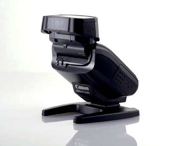
9.36 Speedlite 270EX
9.7.6Disabling AF assist; disabling main flash
Advanced Speedlite models and many cameras have the ability to shut off the AF assist light if it’s obtrusive. All Speedlites with custom functions have one for disabling AF assist, as do many cameras. If both the camera and flash unit have an AF assist custom function, it appears that setting either to “Disable” will shut off the feature. Some cameras can also enable the AF light on an external flash unit while disabling the internal AF assist. Most later digital EOS bodies can control a Speedlite’s custom functions from the External Speedlite control (ESC) menu.
Some camera/flash unit combinations can let an external AF assist light illuminate while preventing the flash tube from firing, which is a useful solution for improving low-light autofocus performance. This is usually done through a custom function or menu item. To do this on a camera with ESC compatibility, for example, go to Flash Control and select Flash firing. Set it to Disable. Be sure that the flash unit is set to emit the AF assist. ![]() 9.37
9.37

9.37
Some cameras from the EOS 7D onward are capable of distinguishing Speedlites that have true AF assist lights (incorrectly described in camera menus as “IR AF assist beam only”—they are red but not IR—from units that pulse the main tube. Such cameras can be set to allow true AF beams to fire while disabling the annoying main tube pulse.
9.7.7AF assist with the Speedlite Transmitter ST-E2
The Speedlite Transmitter ST-E2 is a small master device that uses optical wireless E-TTL to command slave flash units, but which can’t produce any visible white light itself. However, it does have autofocus assist LEDs. If your camera has poor low-light autofocus, you may find the ST-E2 useful, since it’s small and runs for ages on a disposable lithium battery (though when it’s on, the minimum shutter speed in P mode drops to 1/60 sec). Unfortunately, the Speedlite Transmitter ST-E3-RT for radio lacks AF assist LEDs. ![]() 9.38
9.38

9.38
9.8Redeye and greeneye

Redeye, the bane of point-and-shoot snapshots, occurs when light hits the fine red mesh of blood vessels lining the retina of the eye and is reflected back to the camera. Glowing red eyes, like a cheesy special effect from a low-budget movie about demonic possession, are the result.

9.39
While common in photographs, redeye is rarely seen by the naked eye for three reasons. First, the light source has to be much brighter than the ambient lighting. Second, the subject’s pupils must be quite dilated (open) for the reflected red light to be noticeable. And third, and most important, the light source has to be as close as possible to the viewing axis (i.e., to the eye of the viewer).
Unfortunately, these three conditions are met handily when doing flash photography in dim lighting. Flash involves a tremendous burst of light. Since ordinary consumer flash units are attached to the camera or built into the camera body, they’re often located very close to the lens. Tiny point-and-shoots are particularly vulnerable to the problem, partly because they tend to be used in low-light situations like restaurants and living rooms, and partly because their built-in flash units are located very close to the lens.
Flash photography of cats and dogs can involve a related problem called greeneye. Cats and dogs have a reflective membrane in their eyes called the tapetum lucidum, which helps their night vision. The tapetum reflects light very efficiently and tends to color it green, yellow, or blue. The membrane also causes the eyes of animals by the side of the road at night to be visible as brilliant points of light. Humans lack this layer, so we don’t have tapetal reflections. ![]() 9.40
9.40

9.40 The eerieness of greeneye in a cat.
9.8.1Redeye reduction
Redeye can be colored over with a black pen on the final prints or painted over using image-editing software, but these are obviously crude solutions. The best ways to get rid of redeye are either to avoid flash altogether or to move the flash unit as far away as possible from the lens (while still illuminating the scene effectively, of course!).

9.41 A Canon G9 point-and-shoot, a 50D with popup flash, a 50D with shoemount Speedlite 430EX, and a 50D with a 430EX on a Custom Brackets CB Junior bracket. Note the relative distances between the center of the lenses and the center of the flash units.
Good techniques for reducing redeye are to use off-camera flash, put the camera onto a flash bracket, or tilt the flash head so that light bounces off the ceiling or the wall. Unfortunately, none of these techniques are possible with a camera’s unaided built-in flash unit.
One drawback to moving the flash unit, aside from the inconvenience, involves low-light photography. When light levels are low, the pupil of the eye dilates to let in more light, just like a lens diaphragm. If a flash photo is taken of a person, the irises don’t have enough time to react to the burst of light, so the pupils remain dilated and huge.
Because redeye compensation techniques are inconvenient, camera makers have come up with another solution: shine a bright light into the eyes first, which makes the pupils contract and less likely to reflect red light. Some consumer-oriented cameras have redeye reduction lamps—bright white lights or short pulses of blinding light from the popup flash unit. Unfortunately, these lights usually have the effect of making people look dazed and stunned. Blank and glazed, or red and evil looking: with onboard flash photography, the choice is yours!

9.42
Redeye reduction is typically enabled by a menu item or pushbutton, and is indicated by a small eye icon (figure 9.42). Many cameras show a graphical countdown timer while the redeye reduction light is glowing. This is meant to guide the photographer as to how long their victims must stare into the light to let their pupils contract. ![]() 9.43
9.43

9.43
None of these tricks are particularly useful for photographing pets, whose eyes are like reflective road signs or safety tape on high-visibility vests. In these cases, off-camera or bounce flash is the way to go. The light is still reflected back to the source; it just happens to be in a different location than the camera lens.
9.9Flash exposure compensation (FEC)

Flash exposure compensation is the ability to manually increase or decrease a flash unit’s power over the automatically chosen output setting. How FEC is applied depends on the camera and body being used. Many EOS cameras can specify FEC by pressing a button marked with the FEC icon. This engages FEC mode, and rotating the camera’s dial will adjust the flash output. ![]() 9.44
9.44

9.44
Usually the FEC button is tied with another function, such as metering mode or ISO. In such cases, and if the camera has two control dials, each dial controls a separate function.
Other cameras have the ability to apply FEC via a general menu option or the flash control menu.
Many Speedlites have FEC controls on the back. On earlier models, these are the + and – buttons. Later models typically require pressing the SEL/SET button first to activate those buttons. The 580EX and 580EX II have a rotating dial instead of buttons, and a custom function determines if the SEL/SET button needs to be pressed first. The 600EX/600EX-RT and MR-14EX II have a +/– menu option assigned to button 2. The 430EX III/430EX III-RT units have a +/– button: press it and then rotate the dial to change FEC.

9.45

9.46

9.47
When FEC is set to anything other than zero, an FEC icon appears on flash units with displays. Flash exposure compensation isn’t additive on EOS bodies. In other words, if both camera body and flash unit have the ability to set FEC, and the flash unit’s FEC controls are set, the flash unit takes priority and the camera’s adjustments are ignored.
As noted earlier, EOS bodies will apply auto fill reduction under brighter ambient lighting conditions. So it may not be necessary to add any extra FEC in the case of fill flash, particularly when using E-TTL. (Any FEC applied manually is in addition to any auto fill reduction that the camera may apply.)

9.48 Wing of Chinese oak moth, Antheraea pernyi. Flash exposure compensation over a five-stop range: minus two, minus one, normal, plus one, plus two.
9.9.1Micro adjustment for flash exposure
In addition to FEC, some pro cameras, starting with the EOS 1D Mark IV, support “micro adjustment” for flash exposure. This custom function allows the photographer to bias normal flash metering by up to one stop in 1/8 stop increments. It’s essentially a secondary level of flash exposure compensation that can be set permanently and that alters the zero point that FEC starts from.
FE Micro adjustment, as it’s referred to by Canon, is used primarily to customize a camera to suit a photographer’s particular needs and style. It’s also possible to compensate for very minor variations from one camera body to another for precise studio work.
9.10Flash exposure lock (FE lock or FEL)
E-TTL-capable cameras support flash exposure (FE) lock when used with EX flash units. This feature “locks” flash exposure settings until a picture is taken, allowing an image to be recomposed after the E-TTL metering preflash has been sent. This improves flash metering in certain cases. Canon first introduced FE lock in 1986 with the T90 camera and 300TL flash, but subsequently dropped it. FE lock made its return with E-TTL in 1995.
FE lock works by firing the usual E-TTL preflash when the AEL or FEL button is pressed on the camera, rather than just before the scene-illuminating flash is fired. It then stores the flash exposure value in memory, based on a spot metering of that preflash, and waits for you to recompose the image. When you press the shutter release all the way, the camera will fire the flash at the stored power setting.
FE lock is useful for taking photos when the subject is not covered by one of the focus points, when photos contain reflective surfaces that can fool flash metering, or occasionally when the subject is moving. In the case of E-TTL (though not E-TTL II), it’s also useful for scenes in which flash exposure needs to be biased to something other than the current focus point.
The main drawback with FE lock, aside from the extra button pushing, is that the manually triggered preflash can confuse human subjects who may think that a photograph has just been taken when it actually hasn’t.

9.10.1Engaging FE lock
On most EOS cameras, the AE (autoexposure) lock and flash exposure lock features are tied together, so pressing the ![]() button locks both ambient and flash metering. But conveniently, most 1-series EOS cameras have separate FEL buttons that allow for setting the AE lock and FE lock independently. The EOS 10D’s custom function 13-4 allows the assist button to be a dedicated FE lock, and the multi-function M-Fn button (EOS 7D, 6D, 5D Mark III, 1D X, 7D Mark II, and 5DS) can also be used for this function.
button locks both ambient and flash metering. But conveniently, most 1-series EOS cameras have separate FEL buttons that allow for setting the AE lock and FE lock independently. The EOS 10D’s custom function 13-4 allows the assist button to be a dedicated FE lock, and the multi-function M-Fn button (EOS 7D, 6D, 5D Mark III, 1D X, 7D Mark II, and 5DS) can also be used for this function.

9.49 This 50D, like most non 1-series cameras, ties FEL and AE-L to the same button

9.50 Older 1D series cameras have a dedicated FEL button near the shutter release

9.51 Newer cameras, like the EOS-1D X, EOS-1D C, EOS 5DS, EOS 5DS R, and EOS 7D Mark II, have an M-fn button where the old FEL button would have been.
Whichever button is pressed, the camera stores locked flash exposure data for a 16-second period, or for as long as the shutter release is pressed halfway. It will also briefly indicate FEL in the viewfinder, top deck LCD, or rear panel LCD on some camera models; additionally, the ![]() symbol may appear. During this time, the picture can be recomposed in the viewfinder, or the aperture and shutter speed can be altered (overriding AE lock, which is set when the AE lock button is pressed). If the flash symbol in the viewfinder blinks upon setting FE lock, then the subject is too far away to be illuminated sufficiently.
symbol may appear. During this time, the picture can be recomposed in the viewfinder, or the aperture and shutter speed can be altered (overriding AE lock, which is set when the AE lock button is pressed). If the flash symbol in the viewfinder blinks upon setting FE lock, then the subject is too far away to be illuminated sufficiently.
Some cameras have a custom function that specifies whether spot metering and FE lock are to be tied to the central focus point—the default—or to the active focus point instead.
FE lock is not available if the camera is in an icon mode or CA mode, or if digital Live View is enabled. Some early film models may not support FE lock if the flash unit is in high-speed sync mode. If the flash unit also supports TTL, it must be in E-TTL mode for FE lock to function.
9.10.2Flash exposure level
Most 1-series professional Canon cameras have the ability to display the flash exposure level in the viewfinder. When the FEL or M-Fn button is pressed (the small button near the shutter release) a vertical sliding scale will appear in the viewfinder on the right side. ![]() 9.52
9.52
The flash exposure level will be displayed on the far right bar of this scale. The flash output can then be adjusted via flash exposure compensation.

9.52
9.11Fill flash ratios
A traditional model for thinking about artificial light in photography is the ratio. In a two-light portrait, for example, a photographer might consider the ratio of the key light (the main light illuminating the photo) to the fill light (the secondary light that fills in the shadows). Ratios are used in the context of fill flash as well, and are used to describe the amount of ambient (available) light illuminating a scene compared to the amount of flash.
However, ratios aren’t a very useful model for automated flash; particularly fill flash. There are a number of reasons for this. First, there are two different ways of specifying a ratio, depending on whether you’re considering light output (incident light) or reflected light bouncing off a surface. Second, ratios may make some sense in a studio where it’s easy to have full control over all light sources, but it’s not at all straightforward when dealing with ambient light. Third, when using automated flash systems it isn’t really possible for the photographer to measure the flash output. And finally, EOS cameras don’t use the ratio model for specifying flash output anyway. They do unfortunately use ratios when dealing with controlling the output of wireless flash groups, but that’s a different topic altogether.
The first point can lead to a lot of confusion. Does a ratio refer to the ratio of ambient light plus fill flash combined, compared to fill flash alone (effectively the reflected light that makes its way back to the camera)? Or does it simply mean the ratio of ambient light to fill flash (the incident light hitting the subject)? For example, a fill flash ratio of 1:1 can mean that the flash is the sole source of light. Or 1:1 can mean that the flash and ambient light levels are the same. These are two very different situations.
When using automatic flash metering, EOS cameras work in terms of “compensation” rather than ratios. In other words, in bright light conditions the camera will attempt to illuminate the foreground with a flash output that its designers think should work well. With experience, and judicious examination of the preview screen in the case of digital, it then becomes possible to know if this automatic setting works for you. If it doesn’t, you can increase or decrease the flash output using flash exposure compensation with most cameras and flash units. This is done in terms of “stops” of output (see section 6.17).
9.12Auto fill reduction
EOS cameras use regular flash exposure with no compensation when ambient light levels are low, i.e., 10 EV or lower (see section 7.17). However, when ambient light levels are bright, 13 EV or higher, the camera switches to fill flash mode and reduces the flash unit’s output level. This feature, sometimes called “automatic reduction of flash output,” works in TTL mode by dropping flash output by 1.5 stops. Between 10 and 13 EV, the camera smoothly lowers the flash unit’s output by half a stop for each EV.

9.53 This strongly backlit photo is a great situation for automatic fill flash. Notice how E-TTL II has filled in the foreground without blowing it out badly, and without resulting in a flat cardboard cutout look.
E-TTL flash works in a similar fashion, though flash output may be lowered by as much as two stops when ambient lighting is bright. It does so in a more sophisticated fashion than TTL, since it examines each zone as lit by ambient and preflash to compensate for highly reflective areas. The E-TTL fill reduction algorithms have not been published.
Some mid- to high-end EOS cameras allow auto fill reduction to be disabled by means of a custom function (see flash exposure compensation, sections 2.2 and 6.17). Any flash compensation applied manually is in addition to this auto fill flash reduction.
9.13Flash exposure bracketing (FEB)

The 500/600 EX series Speedlites and the three EX macro units all support flash exposure bracketing. This is similar to auto-exposure bracketing (AEB), only instead of changing ambient exposure settings the camera locks the shutter speed and aperture. Then it shoots a series of three photographs with normal flash exposure settings, positive flash compensation, and negative flash compensation. ![]() 9.54
9.54

9.54 Chrysanthemum taken with flash exposure bracketing: normal, minus 1 stop, plus 1 stop.
Bracketing values can be in half, third, or full stops, and the flash star icon may appear in the viewfinder during the sequence. FEB auto cancels once the three-photo sequence is complete and uses whichever drive mode the camera is in. FEB can be used together with both flash exposure lock (FE lock) and flash exposure compensation (FEC).
9.14High-speed sync (HSS)
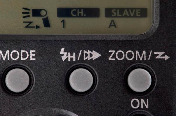
High-speed sync, described fully in section 7.12, is a technology that rapidly pulses a flash unit in order to surpass a camera’s flash synchronization limit (X-sync). HSS flash is turned on by a switch on some flash units, by pressing the + and – buttons simultaneously on others, and by pressing a high-speed sync/second curtain sync button on yet others. On new units like the 430EX and 580EX II, pressing the HSS/second curtain button cycles through three sync choices: HSS, second curtain (if the flash unit is not in wireless mode), and normal first curtain. On most Speedlites with dot matrix screens, pressing the SYNC button (function button 4) cycles through the choices. On the 430EX III/430EX III-RT, press SEL/SET, rotate the dial until the sync icon to the left of the exposure scale is highlighted, then press SEL/SET and turn the dial to select the third sync mode, marked with an H. ![]() 9.55
9.55

9.55
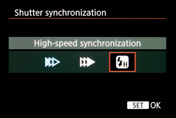
High-speed sync and second curtain sync are mutually exclusive, since the former pulses the flash continuously for the duration of an exposure, whereas the latter fires the flash just once at the end of an exposure. Cameras with menu control over Speedlites (ESC) can set HSS mode by selecting “Hi-speed” or “High-speed synchronization” from the “Shutter sync” menu. ![]() 9.56 and 9.57
9.56 and 9.57

9.56
HSS mode is indicated by the ![]() symbol appearing on the flash unit’s LCD or by an indicator LED. The mode is confirmed by the same symbol in the viewfinder. If this symbol does not appear but HSS is engaged on the flash unit, then the shutter speed is below the camera’s X-sync speed.
symbol appearing on the flash unit’s LCD or by an indicator LED. The mode is confirmed by the same symbol in the viewfinder. If this symbol does not appear but HSS is engaged on the flash unit, then the shutter speed is below the camera’s X-sync speed.
When the flash unit is in HSS mode, you can set a shutter speed higher than the camera’s X-sync. The flash unit will revert to normal flash firing behavior if the shutter speed goes back down below X-sync. Canon Speedlites will remember the HSS mode setting and will switch back to it if the shutter speed is set beyond X-sync once more, but some third-party flash units will inconveniently cancel HSS mode if the shutter speed drops below X-sync.
9.57
HSS mode produces about half the output of normal flash, and the range decreases inversely to the shutter speed. This could be a serious impediment when using a smaller flash unit, if the subject is far away, or if using a low ISO setting. The distance range display on the flash unit can be a useful tool for evaluating whether HSS will work for you when in direct flash mode.
HSS mode is only available with EX-series flash units on type A bodies (with one exception: the EOS 1N film camera could be reprogrammed by Canon to add HSS). No EOS popup flash supports HSS. HSS is available in radio wireless mode only with radio-aware cameras released after 2012.
9.15Enabling second curtain sync
Second curtain sync, described in section 7.13, records more natural motion trails of moving objects when using flash. Availability of the feature is entirely dependent on the specific camera/flash unit combination that’s being used. Here things get a little complicated.
Physical controls on flash unit
Any Speedlite with its own physical controls can use second curtain sync with virtually any EOS camera. The type of control used depends on the model, but it is usually a button or switch marked with a triple triangle symbol or the word SYNC.
On the 430EZ and early EX models such as the 550EX, the + and – buttons must be pressed simultaneously to engage second curtain sync. On the 300EZ and 300TL, there’s a small slide switch. On the 430EX, 580EX, and their Mark II versions, a button marked with the ![]() symbol is pressed to cycle through sync modes. Press once to engage high-speed sync (
symbol is pressed to cycle through sync modes. Press once to engage high-speed sync (![]() ), press twice to engage second curtain sync, and press once more to return to normal first curtain sync. Most Speedlites with dot matrix screens use function button 4, marked SYNC, to cycle through to second curtain mode. On the 430EX III/430EX III-RT use the same method for enabling high-speed sync as above, only select the second curtain sync icon (second of the three icons).
), press twice to engage second curtain sync, and press once more to return to normal first curtain sync. Most Speedlites with dot matrix screens use function button 4, marked SYNC, to cycle through to second curtain mode. On the 430EX III/430EX III-RT use the same method for enabling high-speed sync as above, only select the second curtain sync icon (second of the three icons). ![]() 9.58
9.58

9.58
Second curtain sync can’t be enabled if the flash unit is in any wireless mode.
Custom functions/menu items
Most midrange and professional EOS bodies from the early 1990s onwards have a custom function or menu setting that enables second curtain sync. If both the camera and the flash unit have second curtain controls, then the physical switch or button on the flash unit takes priority. These function/ menu settings default to first curtain sync.
Second curtain and external Speedlite control (ESC)
Post-2007 EOS cameras can communicate with recent Speedlites to enable a host of different flash unit settings, as detailed in section 9.30. Such cameras can control second curtain sync on compatible recent Speedlites. Select Shutter sync. and choose first or second curtain. ![]() 9.58
9.58
Unfortunately, on some camera models the “Flash control” menu item titled “External flash func. setting” cannot communicate with older flash units. Since most of these cameras lack a second curtain sync custom function, you’re stuck.
In short, such cameras cannot engage second curtain sync when using older Speedlites that lack physical controls on the flash unit itself. You can only engage second curtain sync if the flash unit has physical controls, or if it’s a recent model capable of full function control. See appendix C for a list of flash units and cameras that have this menu feature.

9.59
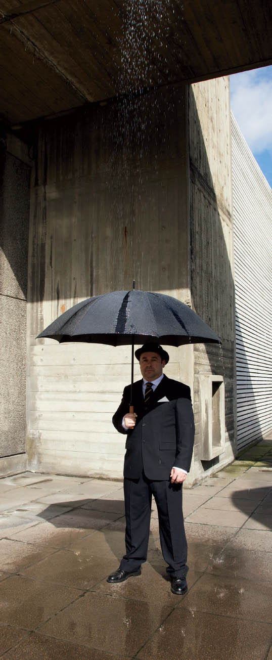
9.60 This shot used wireless E-TTL from a 580EX master on the camera to trigger a 580EX II positioned above the model to light the falling water. However, because second curtain sync isn’t possible wirelessly, the water drops look like they’re falling upwards because the image was shot with first curtain sync.
9.15.1Second curtain limitations
Second curtain sync has a number of specific limitations. First, it can only be used in the “creative zone” modes: P, Av, Tv, M, B, DEP, and A-DEP. It can’t be enabled in any icon mode, green rectangle mode, or CA mode. Second curtain sync is also incompatible with both stroboscopic and high-speed sync modes, and it cannot be used with either optical or radio wireless E-TTL. Second curtain cannot be activated if the shutter speed is faster than about 1/60 sec. Finally, second curtain sync does not work with all-manual flash units (next section).
9.15.2Enabling second curtain sync with manual equipment
EOS cameras only support second curtain sync when using Speedlites connected directly or via an off- camera shoe cord. When using sync-only manual flash, the camera cannot command a flash unit to fire when the shutter is about to close. This is because EOS cameras send the sync command digitally in second curtain mode, rather than simply triggering the hotshoe’s center pin. The same issue affects sync-only radio triggers (section 11.10). Accordingly, second curtain sync will not work in sync-only situations unless the flash unit or radio trigger supports its own implementation of second curtain sync (PocketWizard and Quantum, for example).
There is one workaround, though it is a little inelegant and doesn’t work with sync-only radio triggers. The trick is to use a Canon Speedlite to trigger manual gear equipped with an optical slave. For this to work, the Speedlite cannot be in E-TTL mode because the preflash will set off the slave unit too soon (section 11.7.3).
The best solution is to use a Speedlite with manual output control. Set the Speedlite to second curtain sync and put it in M mode at a low power, such as 1/64 or 1/128. This lets the flash unit send a pulse of light bright enough to trigger a nearby optical slave unit, but not bright enough to contribute much light to the scene. Even ancient EZ units can be used this way. For example, the 430EZ doesn’t support E-TTL, but it can fire in manual second curtain sync mode when used with a new EOS digital camera.
9.16Manual flash
High-end Canon flash units support full manual mode, which lets you specify the flash power by hand, rather than relying on an automated system like TTL or E-TTL. Note that manual flash metering is not the same thing as the camera’s manual exposure (M) mode; the latter is used for ambient (non-flash) light metering. For more information, review chapter 10 on manual flash metering.
Flash output is specified in fractions, from 1/1 (full power) to the minimum power output setting: 1/64 or 1/128, depending on the model. Some units allow for additional sub-increments between these fractional settings. The sub-increments may be half a stop or one-third stop, and are particularly useful for the big drop in power between full power and half power.
Speedlite 420EZ
Press the MANU button to engage manual mode. Press MANU repeatedly to cycle through the manual power output settings.
Speedlites 430EZ, 540EZ, 550EX, 430EX, 430EX II
Press the MODE button to cycle through mode settings until the letter “M” appears on the LCD. To change output, press the SEL/SET button. The output setting will start to blink. Press the + or – buttons to increase or decrease the power. Press SEL/SET to confirm the change. ![]() 9.61
9.61

9.61 A 430EX set to 1/4 manual power with an additional minus 1/3 stop
Speedlites 430EX III, 430EX III-RT
Press the MODE button in the central group of buttons. Rotate the dial until M is selected, then press SEL/SET. To change the output level, press the +/– button in the central group, then rotate the dial until the desired level is selected. Press SEL/SET to confirm.
Speedlites 580EX, 580EX II
Press MODE until the M appears, then press SEL/SET. The output setting will start to blink. Rotate the dial to increase or decrease the power. Press SEL/ SET to confirm the change.
Speedlites 600EX, 600EX-RT
Press MODE until M appears, then press function button 2 (+/–). The output level will appear on a scale on the LCD. Rotate the dial to increase or decrease the power. Press SEL/SET to confirm the change. ![]() 9.62
9.62
9.62
Flash units with menu control have sliders on the camera’s LCD for adjusting manual output. Recent low-cost flash units such as the 90EX, 270EX, and 270EX II, are manual capable but only when used with an EOS camera that has menu controls built in. (They lack physical buttons for manual control.) ![]() 9.63
9.63

9.63
With digital SLRs, it’s easy to adjust manual flash settings by hand and conduct some simple lighting tests. The camera’s preview screen is then used to evaluate the results.
9.16.1Manual flash calculations
Since light output falls off over distance in a predictable fashion, it’s possible to perform distance calculations by hand.
Speedlites with manual controls and rear LCD panels can perform these calculations automatically. For completeness, these are the steps to do it, though frankly this functionality is rarely used by most photographers.
- Set the camera to either Av (aperture priority) or M (manual exposure) mode. The camera can be set to other “creative” zone modes, but the aperture symbol will flash to indicate a problem and the picture’s flash metering will probably be out.
- Set the flash to manual mode, as above.
- Press the shutter button halfway. The flash will display the current aperture and a distance setting.
- If the camera is in Av mode, the shutter speed will be the camera’s X-sync speed and the aperture can be set manually. In M mode, the shutter speed can be any value from 30 seconds to the camera’s X-sync, and the aperture can be any setting within the physical abilities of the lens.
- Adjust the settings so that the distance information on the flash matches the number on the distance scale on the lens. If the lens lacks a distance scale, then the distance will have to be estimated or measured.
- Once everything’s set correctly, the shutter release can be pushed all the way to take the photo, assuming the “flash ready” lightning bolt is displayed in the viewfinder.
The flash unit can’t perform useful calculations if the flash head is in bounce mode—the calculations must be done manually by measuring the flash-to-subject distance. In bounce mode it’s not the distance from the flash to the subject that’s important; it’s the distance that the light actually has to travel from the flash to the reflecting surface and then to the subject. Light loss from the reflecting surface must also be factored in, which can only really be done by experience or judicious use of a flash meter. The flash unit’s guide number is measured in meters and for ISO 100. Additional arithmetic is required when using feet and/or a different ISO.
9.17Optical wireless E-TTL flash

As of 2012, there are two Canon-supported ways to control a remote Speedlite wirelessly: 1) optical (coded pulses of light or infrared) and 2) radio (radio wave transmissions). Optical is widely supported across many EX Speedlites and all type A (E-TTL compatible) cameras. Speedlites that have both optical and radio wireless capabilities use the ![]() icon to specify optical wireless.
icon to specify optical wireless.

Different models have different ways of entering wireless E-TTL, a mode described in detail in section 11.8. Canon identifies wireless E-TTL controls with a Z-shaped icon. The exact configuration of this icon depends on whether the unit is a slave, master, or capable of being both.

A Z with arrows on each end refers to a unit with master/slave capabilities. A Z with an arrow pointing towards the flash unit icon means slave mode, and a Z with an arrow pointing away from the flash unit icon means master mode. The white wireless icon is not to be confused with the blue PictBridge icon on some digital cameras, which looks very similar.
Physical switches
The 420EX, 430EX, 550EX, and 580EX have a convenient physical switch at the bottom, which reads either OFF—SLAVE or OFF—MASTER—SLAVE. This switch makes it easy to move rapidly from mode to mode, which is of particular importance to news or wedding photographers who need to jump from on-camera flash to wireless flash immediately.
Confusingly, OFF means wireless optical mode off, not main power off—it should probably have been labeled SINGLE or SOLO or something less ambiguous. When the switch is in master mode, the flash unit only sends wireless control signals to slave units. When the switch is in slave mode, it only receives wireless commands. The 270EX II has a three-position switch, for OFF, SLAVE, and ON. ![]() 9.64
9.64

9.64
Pushbutton controls
The 430EX II and 580EX II, which have camera menu control over Speedlite functions, have a hidden and less convenient pushbutton control. Pressing and holding the ZOOM/wireless icon button for two or three seconds will cause the tiny wireless icon to blink. To change a 580EX II from master to slave mode, rotate the control dial after holding the ZOOM button. Press the SEL/SET button to confirm the choice. Pressing and holding the ZOOM button puts the 430EX II into wireless slave mode. ![]() 9-.65
9-.65
9.65
This awkward button-pushing necessity takes a moment, which can seem an eternity in fast-moving situations. The ZOOM button also controls quite a few separate features, making it easy to select something else by mistake. For those reasons, many photographers relied on switch-equipped 550EX and 580EX units as their on-camera masters until the advent of radio wireless.
The 600EX/600EX-RT and 430EX III/430EX III-RT have a special button marked with the ![]() symbol. Pressing this button sets the unit to optical wireless master mode when the lightning bolt (
symbol. Pressing this button sets the unit to optical wireless master mode when the lightning bolt (![]() ) and MASTER icons are displayed. Another press of the button switches the unit to radio wireless slave mode. See section 9.19 for radio wireless mode.
) and MASTER icons are displayed. Another press of the button switches the unit to radio wireless slave mode. See section 9.19 for radio wireless mode. ![]() 9.66
9.66

9.66
Note one confusing point: the 430EX III and 430EX III-RT can both serve as optical slaves, but neither can serve as optical masters. However, the 430EX III-RT can be a radio master or a radio slave.
Menu controls
On-camera menu controls (external Speedlite control) for enabling and controlling optical wireless are available for certain camera/Speedlite combinations (see section 9.32). The menu is a bit buried but offers a generally more intuitive interface. And for smaller flash units with virtually no physical controls, such as the 90EX and 270EX II, menu control is actually the only way to adjust flash settings. ![]() 9.67
9.67

9.67
Macro units
The MR-14EX and MT-24EX go into optical wireless mode when group C is enabled. This is done by pressing the RATIO button until CH appears (MR-14EX and MT-24EX) or the lightning symbol and MASTER (MR-14EX II).
9.17.1Changing optical wireless E-TTL settings
Once slave or master mode is set, the user interface for changing optical wireless settings is not the easiest Canon flash feature to understand. It also varies from model to model.
On flash units with LCD panels, optical wireless master mode is indicated on the LCD by the ![]() icon or the word MASTER, with the number below CH indicating the current channel. Optical wireless slave mode is indicated by the word SLAVE, with a letter below SLAVE indicating the current group. On flash units without LCDs, groups and channels are indicated by LED lights, switch positions, or camera menu settings.
icon or the word MASTER, with the number below CH indicating the current channel. Optical wireless slave mode is indicated by the word SLAVE, with a letter below SLAVE indicating the current group. On flash units without LCDs, groups and channels are indicated by LED lights, switch positions, or camera menu settings. ![]() 9.68
9.68

9.68
9.17.2Changing optical channels and groups
Speedlite 420EX
There are separate buttons for changing channels and groups. Pressing each button cycles through the available settings, and an LED will illuminate to indicate the selection. The unit must be in wireless slave mode (the small switch near the flash foot) for these to work.

9.69
When the unit is in slave mode, press the ZOOM button until either CH or SLAVE starts blinking. Use the + and – buttons to select the channel or group.
Speedlites 430EX III and 430EX III-RT
Press SEL/SET, then use the dial to choose one of the four channels: shown on-screen as “Ch.” 1 through 4. Groups A, B, or C can also be chosen.
Speedlite 320EX
The 320EX has physical switches for slave mode, channels, and groups.
Speedlite 550EX
Press the SEL/SET button to cycle through a series of options: flash exposure compensation/flash exposure bracketing/ratios/channels/groups/master firing on/off. When the CH icon starts blinking, press the + or – buttons to change channels. If the flash unit is in slave mode, SEL/SET will allow the group to be selected. Pressing + or – changes the group, which is oddly marked by the SLAVE icon, not by the word GROUP.
Speedlites 580EX and 580EX II
Pressing (but not holding) the ZOOM button if the unit is in master or slave mode will cycle through a series of options. These options include: zoom setting/ratio (in master mode)/channel/master flash firing (in master mode)/group (in slave mode). If the CH or SLAVE symbols start blinking, turn the control dial to change channels or slave groups.
Macro lites MR-14EX and MT-24EX
These units can change channels for external Speedlites in group C. To do so, press the recessed CH button to cycle through the four channels. Groups A and B are always assigned to the left and right macro tubes in these units.
Speedlites 600EX/600EX-RT and ST-E3-RT
From the main menu on the Speedlite, press button 4 to bring up MENU 3. Then press it again to bring up MENU 2. Now function button 1 changes to CH for channel. Press button 1, and use the dial to choose the channel (1–4) that you want. Press SEL/SET to confirm.
Macro lite MR-14EX II
From the main menu, press button 4 to bring up MENU *. Function button 1 will change to CH for channel. Press button 1, and use the dial to choose the channel (1–4) that you want. Press SEL/SET to confirm.
Speedlites 90EX and 270EX II
These tiny units lack physical controls to speak of, and must be configured through the camera’s ESC menu.
9.17.3Enabling and changing ratios
Optical wireless E-TTL slaves can be in one of three groups, and it’s possible to change the relative output levels of each group. Changing output ratios between the three slave groups is rather confusing and non-intuitive: the relationship between groups A and B is a ratio, whereas group C has an exposure compensation (+/–) relationship to groups A and B when taken as a unit.
Optical wireless is structured this way because it assumes a specific lighting model: groups A and B are the key and fill lights, with C being a background highlight. Radio wireless E-TTL has a more flexible five-group system.
Enabling ratios
On the 550EX, make sure the unit is in master mode, then press the SEL/SET button repeatedly and cycle through the choices (flash exposure compensation/flash exposure bracketing/ratio/channel/master firing) until RATIO starts blinking. Press +/– to select A:B ratios, A:B C ratios, or no ratios (OFF).
The 580EX and 580EX II have similar controls, only the ZOOM button, not SEL/SET, cycles through the modes (zoom/channel/master firing/ratio). Once “RATIO” starts blinking, rotate the control dial to enable or disable the three settings—RATIO A:B, RATIO A:B:C, and RATIO: OFF.

9.70 Ratio slider
The MR-14EX and MT-24EX are actually a lot easier to use, since they have dedicated “RATIO” buttons. Pressing this button once enables A:B (tube left and tube right), and pressing it again enables A:B C (tube left, tube right, and external Speedlite). Pressing it a third time reverts the unit to both tubes and no external Speedlite firing.
On the 600EX/600EX-RT, press function button 4 to get MENU 2 to appear. Then press function button 2, and choose RATIO A:B or RATIO A:B C as required. The 430EX III and 430EX III-RT cannot serve as optical wireless masters.
Changing A:B ratios
Once ratios are enabled on the 550EX, press the SEL/SET button repeatedly to cycle through the choices until both RATIO and the mark on the A:B slider start to blink (i.e., it isn’t possible to adjust the actual ratio setting until the mark itself starts blinking).
On the 580EX or 580EX II, enable ratios as above. Then press the SEL/SET button repeatedly to cycle through the choices: flash exposure compensation/flash exposure bracketing/A:B ratio/C compensation.
Once the small mark on the slider starts blinking, it is possible to adjust the A:B ratio on the horizontal output A:B display, ranging from a ratio of 8:1 to 1:1 to 1:8. Use the + or – buttons or the dial to move the mark position, indicating the ratio of A to B output. ![]() 9.70
9.70
Again, the MR-14EX and MT-24EX are much easier to use, as they have ratio adjustment buttons in addition to a RATIO button. Once the ratio slider is on-screen, simply press the < and > buttons to adjust the slider mark.
On the MR-14EX II, press the RATIO button to enable A:B ratios. To change the A:B ratio, press function button 3 (Gr) and then use the dial. SEL/SET to confirm. You can also press the RATIO button to cycle through the A tube only on, or the B tube only. ![]() 9.71
9.71

9.71
See the steps above for enabling A:B ratios on the 600EX/600EX-RT. Press function button 3 for Gr (group) functions. Press function button 3 for A:B +/– , and then use the dial to set the ratio of A to B slaves. Press function button 4 (![]() ) to exit the menu system.
) to exit the menu system.
Changing C compensation
Make sure that the “RATIO” choice is set to A:B C to enable all three groups.
On 500 series units, press SEL/SET repeatedly and cycle through the choices until “RATIO C” starts blinking. It is then possible to specify the number of stops of compensation for the C group relative to A and B, from –3 to 0 to +3 stops. This is done either by pressing the + and – buttons on the 550EX or rotating the dial on the 580EX or 580EX II.
On the MR-14EX or MT-24EX, use the + and – buttons to add or subtract group C compensation. To get this function once ratios are enabled, press SEL/SET repeatedly to cycle through the choices until “RATIO C” starts blinking.
On the MR-14EX II ring lite, use custom function 15 to enable slave group C support if necessary. Press the RATIO button to display RATIO A:B C. Make sure the channels are correct for master and slave.
9.72
See the steps above for enabling A:B C ratios on the 600EX/600EX-RT. Press function button 3 for Gr (group) functions and select group C. Press function button 3 for C +/– , and then use the dial to set the ratio of A to B slaves. Press function button 4 (![]() ) to exit the menu system.
) to exit the menu system.
On the 430EX III/430EX III-RT, set “A:B C” using the method above, and then use the dial to select the amount of flash exposure compensation for channel C.
External Speedlite control (ESC)
If your camera and Speedlite combination has ESC for flash menu control (section 9.30), you can set flash ratios in a much more intuitive fashion by using the on-camera menus. Somewhat confusingly, the in-camera menu control may describe no ratios as RATIO A+B+C (i.e., all slave groups have the same output level). ![]() 9.73
9.73

9.73
9.17.4Specifying optical wireless flash output manually
In addition to automatic ratios, wireless E-TTL allows manual flash output power to be set for the three groups separately on all 500 and 600 series EX units.
To do so, press the master flash unit’s MODE button until M is displayed. Then enable RATIOs as above. When the flash unit is in wireless mode but with manual metering, the RATIO function allows each of the three lettered flash groups to have its output set manually. This is set from 1/1 (full power) to 1/128, though unfortunately only in full stop increments. The group being set will have its letter underlined. When output power is set by hand, no automatic flash metering is performed.
Individual slave units can also be set to manual mode. The key is to switch the flash unit to slave mode, then press and hold the MODE button until M appears. It’s even possible to set a wireless slave to MULTI (stroboscopic) mode this way; additionally, 1/2 or 1/3 stop increments are possible on slave units.
9.17.5Master flash firing on/off
Some master units can be instructed not to fire (i.e., not to contribute any scene-illuminating light) while still controlling remote slave units. While the master unit won’t contribute any light to the scene when off, it will still fire a visible preflash to command the slave units in optical wireless mode.
On the 550EX, press the SEL/SET button repeatedly and cycle through the options until flash on/off is selected. This is indicated by a blinking icon showing the flash unit emitting light. Press the +/– buttons to change this setting to ON or OFF.
On the 580EX/580EX II, press the ZOOM/![]() button while the unit is in master mode. The word ON and the tiny “flash emitting light” icon should blink on the screen. Turn the control dial so that the word OFF (it looks a bit like “0 FF” on the 580EX) blinks instead.
button while the unit is in master mode. The word ON and the tiny “flash emitting light” icon should blink on the screen. Turn the control dial so that the word OFF (it looks a bit like “0 FF” on the 580EX) blinks instead. ![]() 9.74
9.74

9.74
On the 600EX/600EX-RT, press function button 4 to bring up MENU 2. Then you can press function button 1 to turn master flash firing on (![]() ) or off (
) or off (![]() ).
).![]() 9.75
9.75

9.75
9.18Integrated Speedlite transmitter: using built-in flash as master
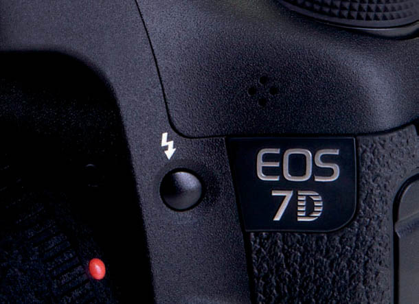
No EOS camera built before 2009 could use its popup flash to command slave flash units. Since then, the 7D, 60D, 70D, 7D Mark II, Rebel T3i/600D, Rebel T4i/650D, and Rebel T5i/700D, have “integrated Speedlite transmitter” capabilities and can send optical wireless commands by pulsing the built-in flash unit. No additional master flash unit is required, which is very convenient. You can, for example, carry around tiny slave-capable flash units like the 270EX II for full off-camera wireless flash. ![]() 9.76
9.76

9.76
9.18.1Built-in flash to control one group of slave units
9.77
- Turn on the camera’s built-in flash by pressing the
 popup flash button next to the lens mount.
  9.77
9.77 - Turn on the camera’s menu system and select Flash Control.
- Make sure that Flash firing is set to Enable. If it’s not, optical wireless E-TTL won’t work. 9.78
- Select the “Built-in flash func. setting” menu.
- Make sure that Flash mode is set to E-TTL II. It can be set to Manual, if all-manual optical wireless flash is desired, but optical wireless will not work in MULTI (stroboscopic) mode. 9.79
- Select the Wireless func. menu item and set it to
 . This option will fire remote optical slave Speedlites, but the built-in flash unit will not contribute light to the scene. 9.80
 - Choose the desired channel from 1 to 4 using the Channel menu item. All slaves have to be on the same channel.
- Turn on the slave units and position them as required.
- Press the
 button to fire a test flash.
 - Take the photograph.

9.78

9.79

9.80
9.18.2Built-in flash and ratios
- The cameras have full ratio support, using the traditional A:B ratio with a separate group C.
- Enable optical wireless E-TTL as above.
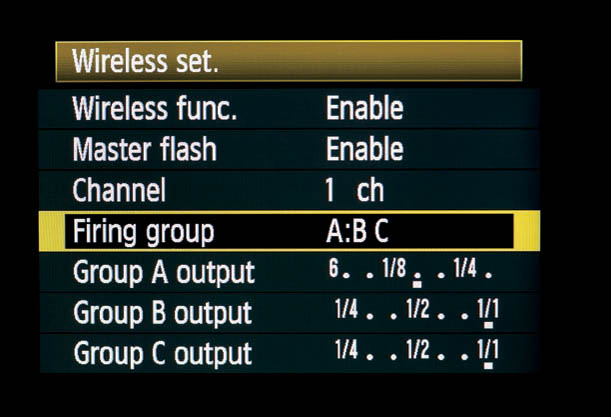
- Choose the desired ratio type from the firing group menu item. 9.81
- If the firing group is set to A+B+C, then all optical slave units will fire simultaneously regardless of which group they happen to be in, so long as they’re on the same channel.
- If the firing group is set to A:B, then a ratio between optical slaves in groups A and B can be set using a slider named “A:B fire ratio.” When the marker on the slider is to the left side (e.g., 4:1), then group A will be brighter. If the marker is to the right (e.g., 1:4), then group B will be brighter. 9.82
- If firing group is set to A:B C, then exposure compensation can be applied to group C as well. 9.83

9.81

9.82

9.83
9.18.3Enabling built-in flash to light the scene
The popup flash unit can be set to light the scene as well as to act as a wireless master. However, this isn’t very useful.
When the built-in flash is firing wireless E-TTL commands off to the slave units, it’s obviously depleting its capacitor. Since there isn’t enough time to recharge the capacitor between issuing wireless commands and the scene-illuminating pulse, there will be considerably less power available to the built-in flash unit. The maximum guide number will drop from 12 to about 4. This limits the built-in flash to adding a catchlight to the subject’s eyes or a similar function.
- To allow the built-in flash to contribute light to the scene, choose the appropriate option from the “Wireless func.” menu. It’s possible to select for slave Speedlites only, or two options, including the
 icon, indicating built-in flash.
9.18.4Wireless all-manual flash
- If “Flash mode” is set to Manual, then the camera is capable of using full manual output control for up to three groups of slave units. E-TTL metering is not used.
- If Wireless func” is set to just , then all remote slaves will fire at the same power.
- The output power is set via the “flash output” slider. Output values can range from 1/1 (full power) all the way to 1/128. The actual output setting depends on the physical capabilities of the slave unit in question—not all Speedlites can go all the way to 1/128.
- If Wireless func. is set to (A,B,C) then up to three separate groups of slave units can be used. The output of each group is adjustable using three flash output sliders. 9.84
- If Wireless func. is set to
 , then the output of all slaves can be set as one group. The output of the camera’s popup flash unit can also be set independently.
 - Finally, if Wireless func. is set to (A,B,C), then the output of each of the slave groups and the output of the camera’s popup flash unit can be set independently.

9.84
9.19Radio wireless E-TTL flash
Wireless E-TTL flash took a big step forward with the introduction of Canon’s radio-based system. At time of writing, three RT (radio) Canon flash models exist—the Speedlite 600EX-RT, the ST-E3-RT transmitter, and the Speedlite 430EX III-RT—but the system will undoubtedly be expanded in the future. The ![]() symbol is used to indicate radio wireless. You can’t use both optical wireless and radio wireless simultaneously: the technologies are independent and completely incompatible. If you’ve got one flash unit that’s optical only, and another that supports both radio and optical, you’ll have to switch the latter over to optical mode to use both units.
symbol is used to indicate radio wireless. You can’t use both optical wireless and radio wireless simultaneously: the technologies are independent and completely incompatible. If you’ve got one flash unit that’s optical only, and another that supports both radio and optical, you’ll have to switch the latter over to optical mode to use both units.

9.85 The 600EX-RT supports a wide range of advanced features, such as mixing and matching metering methods when using wireless.

9.86 A Speedlite Transmitter ST-E3-RT attached to an EOS 5DS camera. This device lets the camera control remote Speedlite flash units over radio waves.
Pushbutton controls
The easiest way to enable radio mode on the 600EX-RT is to press the wireless (![]() ) button until
) button until ![]() appears on-screen along with MASTER. If you want to use the flash unit as a slave remote, press the wireless button again to get SLAVE on the screen.
appears on-screen along with MASTER. If you want to use the flash unit as a slave remote, press the wireless button again to get SLAVE on the screen.
The ST-E3-RT is always a radio wireless master unit and should be displaying MASTER unless the device has been put into LINKED SHOT mode. Next, press the MODE button to show ETTL on the display.
On the 430EX III-RT, press the wireless (![]() ) button to the left of SEL/SET, and then turn the dial until the radio master symbol (
) button to the left of SEL/SET, and then turn the dial until the radio master symbol (![]() ) is displayed. (Note that the 430EX III-RT has both master and slave radio capabilities, but can only act as an optical slave, not an optical master.)
) is displayed. (Note that the 430EX III-RT has both master and slave radio capabilities, but can only act as an optical slave, not an optical master.)
When used with an ESC-compatible (see section 9.30) and radio-aware (see section 11.11.3) camera, it’s also possible to enable a 600EX-RT or 430EX III-RT’s radio mode using a camera’s Speedlite menus. This option is not available to EOS cameras made prior to 2012. ![]() 9.87
9.87

9.87
9.19.1Changing radio transmission channels
The next step is to select a wireless channel. Unlike optical wireless channels, these are true radio-frequency channels representing 15 different sections of the 2.4 GHz band. All master and slave units must be on the same channel for them to work together.
On either the 600EX-RT or the ST-R3-ET, press function button 4 to bring up MENU 3. Then press function button 1, labeled CH. You can then turn the dial to select any channel you want from 1 through 15. Or, if you’d like the flash unit to choose one for you, select AUTO. Then press SEL/SET to confirm your choice. Press function button 4 (the return arrow symbol) to go back to shooting mode.
On the 430EX III-RT, press SEL/SET and rotate the dial until either AUTO or a numbered channel is highlighted on the screen. Press SEL/SET again to choose the channel you want, then SEL/SET to confirm.
Naturally, cameras with ESC menu control can enable channel selection as well.

9.88
9.19.2Scanning for a radio transmission channel
Which channel to use? It’s important to select a channel that minimizes interference from other devices transmitting in the 2.4 GHz range. All kinds of products use this band—phones, laptops, tablets, baby monitors, radio- controlled toys, and home automation systems—so it can get pretty congested. RT Speedlites have both automatic and manual channel scanning for detecting available channels. On the 600EX-RT or ST-E3-RT, press function button 4 to bring up MENU 3. Then press function button 3, SCAN. On the 430EX III-RT, press SUB MENU and then use the dial to select SCAN. ![]() 9.89
9.89

9.89
If your RT unit is currently set to channel AUTO, then SCAN will examine each of the 15 channels and select the channel with the least number of competing devices.
If your RT unit is set to a manual channel, then SCAN will bring up a histogram showing the suitability of each channel. Select the channel with the highest bar using the dial, then press SEL/SET. ![]() 9.90
9.90

9.90
All master and slave units must be on the same channel to work correctly.
9.19.3Wireless radio ID
One extremely handy radio wireless E-TTL feature is that each master/slave configuration can have its own unique four-digit “radio ID” code. This greatly lowers the chances of other people’s flash units within radio range interfering with yours, since there are 10,000 codes to choose from. Just don’t choose anything obvious like 0000 (the default), 1234, or 9999!
On the 600EX-RT or ST-E3-RT, press function button 4 to bring up MENU 3. Then press function button 2, labeled ID. Now you can enter a four-digit code of your choosing. Select a digit using the dial, then press SEL/SET. Use the dial to change the number, then SEL/SET to confirm. Once your 4 digit code is in place, press function button 4 (![]() ). Remember that the master and all slave units must have the same radio ID.
). Remember that the master and all slave units must have the same radio ID.
On the 430EX III-RT, press SEL/SET, then rotate the dial until the four-digit number in the lower left corner of the screen is highlighted. Press SEL/SET, then use the dial to change each of the 4 digits as required. Select “OK” on screen when you’re satisfied.
As always, ESC-equipped cameras can set the radio ID via an in-camera menu.

9.91
9.19.4The LINK light
Radio-capable flash units have an LED, marked LINK, on the back. This light reports on the following situations:
- Steady green: Master and slave units are successfully connected.
- Steady orange: Unit is a master connected to a slave or slaves, but wasn’t the first one to be turned on. It’s therefore a sub-master (see 9.19.5).
- Steady red: No master/slave communication. Perhaps the slave is out of range, or the channel and ID settings are wrong.
- Blinking red: Either there are more than 16 units in total on the same channel and radio ID, or an unspecified error has occurred. For the latter, try turning the power off and then on again.

9.92
9.19.5Multiple masters
When using radio wireless you can use more than one master flash unit. This means you can have, say, two separate cameras, each with their own master flash units attached, controlling the same set of slaves. As long as everything is set to the same channel and radio ID, it all works together.
The first master unit to be turned on and used will have a green link light. Subsequent masters (sub-masters) will have a steady orange link light. Note that there is a limit of 16 devices in total, including all the masters and all the slaves.
9.19.6Two and three groups and ratios (traditional)
Radio wireless E-TTL can use the same two-group (A:B) or three-group (A:B C) systems used by optical wireless by setting the master flash to ETTL mode. In fact, if your camera is radio-compatible but not radio-aware (see section 11.11.3), then this is the only option you’ll have for controlling the light output of more than one flash unit when using radio wireless.
The procedure for setting three-group ratios is essentially the same as with optical wireless. However, unlike optical’s unlimited number of slaves, you can have up to 15 slaves in radio wireless mode.
Configuring a master unit for two or three groups
On the 600EX-RT or ST-E3-RT, press the MODE button and set ETTL. Then press function button 4 to go to MENU 2. Press function button 2, RATIO, and select either RATIO A:B for two slave groups, or RATIO A:B C for three slave groups.
On the 430EX III-RT, press SEL/SET, then rotate until the firing group symbol is highlighted. This is located between the channel/ID section and the exposure compensation slider. Turn the dial to select between ALL (no ratios), A:B (ratio between two groups) and A:B C (two group ratio and group C exposure compensation).

9.93
Configuring ratios for two-group radio wireless
On a 600EX-RT or ST-E3-RT master unit, press function button 3, (Gr) while MENU 1 is displayed. Then press function button 3 again for A:B +/–. Rotate the dial to change the ratio between A and B, and press SEL/SET. Press function button 4 (![]() ) to return the flash unit to the shooting state.
) to return the flash unit to the shooting state.
Configuring ratios for three-group radio wireless
Follow the procedure above on a 600EX-RT or ST-E3-RT. To apply flash exposure compensation for group C, press function button 3 (Gr) and select C. Then press function button 3 again for C +/– and apply compensation as required. Press function button 4 (![]() ) to return.
) to return.
Configuring slave units
On a 600EX-RT, press the MODE button. Then, when in MENU 1, press function button 3 (Gr) and select group A, B, or C as appropriate.
On a 430EX III-RT, press SEL/SET, then rotate until the firing group symbol is highlighted. This is located between the channel/ID section and the exposure compensation slider. Then choose the group you want the slave unit to respond to: A, B, C, D, or E.
Note that if you set the slave to either D or E then the slave unit will not respond to any master unit that’s in three-group mode. Only a master unit set to group (Gr) mode will be able to command a slave unit that is set to groups D or E.

9.94
9.19.7Manual flash in three-group mode.
You can manually control up to three groups of slaves, and manually dial in the output setting for each group. To do so, set the mode to M on the master unit. When MENU 1 is on-screen, press function button 2 (RATIO) and choose either RATIO OFF (fire all slave units regardless of group), RATIO A:B, OR RATIO A:B:C. Then you can press function button 3 (Gr) and choose the group you want to change using the control dial. For each group press function button 3 (*+/–) and use the control dial to specify the fraction of full power that you want the slave group to use.
9.19.8Five group (Gr mode) control
Radio wireless E-TTL also introduces five-group control (A/B/C/D/E), but this feature is only available if your camera is a radio-aware model introduced in 2012 or later. Older radio-compatible cameras are limited to the traditional A:B C group (optical E-TTL) model.
When in five-group mode it’s possible to assign different metering methods to each of the separate groups. So you could, for example, have group A metering with E-TTL, group B metering manual, and group C using Ext.A autoflash if you wanted. Don’t forget that each slave unit needs to be set to respond to the correct group, from A through E. ![]() 9.95
9.95

9.95
Configuring the 600EX-RT or ST-E3-RT as a five-group master
To enable five-group mode on a 600EX-RT or ST-E3-RT, set the master unit to Gr mode by pressing the MODE button. (Though somewhat confusingly, ETTL mode means groups 2–3 only.) Then configure each of the slave groups. Starting in MENU 1, press function button 3 (Gr) and select the group (A through E) that you want to change. ![]() 9.96
9.96

9.96
Once that’s done, from MENU 1 press function button 3 (Gr) and select each group. Press function button 2 (* MODE) to determine if you want the group in question to fire as an E-TTL (ETTL), manual (M) or autoflash (Ext.A) device.
With a given group selected (marked with a black bar) you can press function button 3 (*+/–) and then the control dial to apply the amount of flash exposure compensation (ETTL and Ext.A modes) or raw flash output (M mode) you want. You can also apply flash exposure compensation to all groups at once by pressing function button 2 (+/–) from within MENU 1. ![]() 9.97
9.97

9.97
Configuring the 600EX-RT as a five-group master
To enable five group mode, press the MODE button and then choose Gr using the dial. Press SEL/SET to confirm.
Now you can go through the five groups (A through E) and configure each one the way you want. Press SEL/SET, then rotate the dial to choose the desired group from the lower right section of the screen. Press SEL/SET again to choose a group.
Use the dial and SEL/SET to choose which flash mode you want each group to use – ETTL, M, Ext.A. Use the dial to apply however much raw output (M mode) or exposure compensation (other modes) you require. Note that the 430EX III-RT doesn’t support Ext.A mode as a slave unit, and will not fire if the master unit commands the use of Ext.A mode.
9.19.9Test flash from a slave unit
Since radio wireless E-TTL is bidirectional, you can walk up to a slave unit on the studio floor and use it to trigger a test flash if you wish.
On a 600EX-RT slave unit, press function button 4 to bring up MENU 2. Then press function button 3, TEST, to fire a test shot. Or if you prefer, and if your camera is a radio-aware model, press function button 2 (MODEL) to enable a burst of pulsing light as modeling flash. In the case of multiple masters, only the green master unit will respond.
On a 430EX III-RT slave unit, press SEL/SET and then use the dial to choose MODEL or TEST as required.
9.20Advanced M (metered manual) ambient metering
In a camera’s manual exposure mode, the aperture and shutter speed are both set by the photographer, and these exposure settings combine with the camera’s ISO or film speed to determine how the photograph, as lit by ambient lighting, is exposed. But just because you’re metering manually for ambient light doesn’t mean you can’t use flash as well. Flash can still work fully automatically if you wish, using TTL or E-TTL as appropriate.
This is how flash works in manual mode. Note that this means the manual exposure mode setting only, which can use automatic TTL flash metering (it will not use A-TTL metering in manual exposure mode). Also, it doesn’t refer to setting the output of the flash manually—that’s manual flash and a different topic altogether.
- Set the camera to M for manual exposure mode.
- Set the aperture and shutter speed to expose the background correctly.
- Press the shutter button down halfway if the flash unit has a rear-panel LCD, and the flash coupling range will appear. This range is the distance that can safely be covered by the flash. Note that this only works with direct flash. The coupling range is not calculated when using bounce flash, and the range probably won’t be correct if there’s a diffuser on the flash head.
- If the lens has a distance scale, check the current focusing distance to ensure that the distance to the subject falls within this range. Otherwise an estimate is needed.
- If the “flash ready” lightning bolt symbol appears in the viewfinder, press the shutter all the way to take the photo. The flash’s TTL or E-TTL system will determine the flash exposure level of the subject.
9.20.1Meters and feet
Measurement systems are only used for calculating manual flash ranges, but obviously feet or meters must be available. The 430EZ was sold in two versions: one in feet for the U.S. market and one in meters for the rest of the world. The distance unit types can’t be altered.
The 540EZ and 550EX can display the coupling range in either feet or meters, as determined by a tiny switch in the battery compartment. ![]() 9.98
9.98

9.98
The 580EX has a hidden unit-changing feature: press and hold the C.Fn button until “C.Fn” appears on the LCD, then press and hold the center dial button until the units blink on the screen. Use the dial to change units.
The 430EX II, 430EX III/430EX III-RT, 580EX II, and 600EX/600EX-ST change measurement systems through the custom function 0, which is also accessible via the menu system on compatible cameras.

9.99

9.100
9.21Quick Flash/Rapid-fire mode
Electronic flash units work by charging up a capacitor with electricity, then releasing the stored-up power in a split-second burst of light. The charging process, or “recycle time,” takes up to a few seconds on larger units. This can be a problem if several flash photos have to be taken in fairly rapid succession, such as at a wedding.
Many EOS flash units have the ability to be triggered even if not fully recharged, on the theory that it’s better to take a photo without a full flash charge than have the flash not fire at all. Flash units capable of this feature have a two-color flash ready (“pilot”) light. If the light is red, then the flash is fully charged. If it’s green, then the flash is only partially charged but will still fire anyway. The feature is known as Quick Flash or Rapid-fire, depending on when the model was made.

9.101

Flash duration changing with charge
9.102 This graph shows how a Speedlite will stretch out the flash duration to make up for decreased charge. The example here is at 1/8 power output.
Quick Flash is quite useful. Without it, it’s all too easy to take two photos in succession only to find that the flash unit didn’t fire on the second shot.
If a flash unit is fired when not fully charged, it will attempt to lengthen the time period over which the flash pulse is emitted in order to compensate for the lowered output. If this can’t be done then its light output will be lower than expected.
Quick Flash won’t work if the camera is in continuous shot mode (unless the flash unit has a custom function permitting this to work). It also won’t work if the flash is in manual mode at full or half power, in FEB mode, or if the camera is in stroboscopic flash mode at a fairly fast setting. The 430EZ does not work in rapid-fire mode if an external battery pack is used. The MR-14EX III, 430EX III, and 430EX III-RT also have a CHARGE progress bar that animates to show the capacitor charging up. ![]() 9.103
9.103
9.103
9.22Stroboscopic (MULTI) flash
In “stroboscopic” or “MULTI” mode a 400 EZ series or 500/600 series flash unit can emit brief rapid pulses of light over the course of an exposure. This permits multiple moments of motion to be captured on a single frame. This type of photography is detailed in section 15.8.
To engage stroboscopy, press the flash unit’s MODE button and cycle through the choices until MULTI is displayed on the LCD. This mode can be used on a wireless E-TTL slave unit; the key is to press and hold the MODE button if the unit is performing as a wireless slave. It can also be set using ESC on a compatible camera.
There are a number of parameters that can be set by pressing either the SEL/SET or MULTI buttons, and then pressing the + or – buttons or rotating the input dial, depending on the model. The settings are as follows:

9.104
- The frequency of flashes to be fired per second, specified in Hertz, abbreviated to Hz. 20 Hz means, for instance, that 20 separate pulses of light will fire per second.
- The power output of each burst as a fraction of full power. 1/4 power cannot be exceeded in stroboscopic mode because of the risk of the flash head overheating.
- 500/600 series units can specify the total number of flash bursts to be fired within pre-programmed safety limits. On a 400 series unit the number of bursts must be calculated by hand from the shutter time and the flash frequency. 9.105

9.105
When using a 500/600 series flash unit, the coupling range on the back panel LCD will change as the camera’s aperture is adjusted. Adjust the flash unit’s power output, the lens aperture, and the camera’s ISO (if using digital) so that the coupling range matches the distance to the subject.

9.106 A backlit shot. The model raised her arms slowly as the flash unit pulsed light at 5 Hz.
It takes experimentation to determine the ideal number of light pulses to cover the action and the output settings required to expose the subject correctly. Shutter times in seconds can be calculated by taking the total number of flashes and dividing them by the flash frequency. See the final chapter of this book for stroboscopic examples.
Consult the flash unit’s manual for a table of the total number of flash bursts possible at each frequency/power setting, since each model has different capabilities. For instance at 1 Hz, most 500 models will fire 7 consecutive bursts at 1/4 power, but 100 at 1/128 power. If the number is set to – –, then the flash unit will fire continuously up to its preset limit, which again varies by model. Note that the 580EX and 580EX II have more conservative restrictions than the 540EZ and 550EX in this regard. The safety limits are there to minimize the risk of damage to the flash head from overheating caused by firing too many stroboscopic sequences in a row.

9.107
The EOS 7D can perform stroboscopic flash using its popup flash unit, but this isn’t at all useful due to the low power output of the internal flash.
9.23Flash exposure confirmation LED
Not to be confused with flash exposure compensation, a confirmation light is an LED on the back of many Speedlite flash units. On some units it’s labeled “Auto Check,” though on most it’s not labeled at all. It illuminates for two or three seconds, post-exposure, to confirm that there was sufficient light from the flash to illuminate the subject. Unfortunately, EOS cameras do not have such an indicator in their viewfinders.
The green LED will glow even if the image was overexposed, so it’s not a guarantee of good exposure. It only indicates that the photo was not underexposed due to being out of range. ![]() 9.108
9.108

9.108
9.24Range warning
The earliest EOS film bodies (630, 1, RT) could blink the shutter speed and/or aperture values in the viewfinder if the foreground subject was too close to or too far to be illuminated by flash. All other models lack this warning for patent reasons.
The FE lock feature with type A bodies also has a range warning. If the lightning bolt in the viewfinder blinks when the FE lock button is pressed, then there isn’t enough flash output to illuminate the subject correctly.
9.25Modeling flash
Large studio flash units usually have incandescent bulbs or white LEDs alongside the main flash tube (section 13.2.2). These constant light sources illuminate the subject in much the same way as the actual flash will, only much more dimly. The feature is known as a modeling light, since it allows the effect of the flash to be previewed in a rough fashion. Flash shadows and reflections can be determined in this way.
Canon Speedlite modeling flash simulates the effect of the flash going off before the picture is taken—particularly useful for previewing wireless E-TTL flash ratios. It works by pulsing the flash rapidly (about 70 Hz) for a second, much like high-speed sync mode. This obviously drains the batteries and can overheat the flash unit if triggered repeatedly, so it’s best used sparingly. ![]() 9.109
9.109

9.109
Pressing the camera’s depth of field preview button fires the modeling flash, though this can be turned off with a custom function if it’s inconvenient. Some units must be in wireless slave mode for the modeling light to work, and some can trigger modeling flash using the test button on the flash unit. Both a camera and a flash unit that can support modeling flash are needed to use the feature, and the camera must be in a creative zone (letter) mode. Modeling flash won’t fire if the camera is in an icon mode or if a digital camera has Live View enabled. It also doesn’t work if the flash unit is in radio wireless E-TTL mode and the camera is not radio aware. ![]() 9.110
9.110

9.110
On most cameras that have it, the depth of field button is a small, unmarked button next to the lens mount, positioned immediately below the lens release button (i.e., on the left side of the camera body when looking through the viewfinder). However, for some mysterious reason, the button is located on the opposite side of the lens mount on EOS 1 series cameras. ![]() 9.111
9.111

9.111
Canon’s ring flash units use small white incandescent bulbs or LEDs for focus assist and modeling purposes, not the pulsing of a flash tube.
9.26Auto Power Off/Save Energy (SE) mode
Most Speedlites turn themselves off (also referred to as “Save Energy” or “Energy Conservation Control”) after a set period of time, usually 90 seconds or five minutes, in order to minimize battery drain. Some flash units are always in this mode when powered on.
However, since it can be annoying to have a flash unit turn itself off in the middle of setting up a shot, SE override control is very important for wireless flash. Accordingly, some Speedlites such as the 550EX have a three-position switch (shown here): off, on, and SE. ![]() 9.112
9.112

9.112
 Other units, such as the 600EX/600EX II and the 430EX III/430EX III-RT, use custom function 1 to enable save energy mode.
Additionally, models like the 580EX have custom functions (section 9.29) that extend the time before SE renders the flash quiescent. Other models have a longer timeout period if in E-TTL slave mode.
Pressing the flash unit’s test button or the camera’s shutter release button halfway will wake up the flash and recharge it. When using an N-3 equipped EOS camera with the TC-80N3 timer/remote controller, the inter-valometer on an EOS 10/10s, a 600-series camera with the Technical Back E, or an EOS 1 or 1N with the Command Back E1, the camera will wake up the flash unit a minute or so prior to taking a photo in order to give it time to recharge. ![]() 9.113
9.113

9.113 Auto power off menu
9.27Speedlite autoflash/External flash metering
As discussed in section 5.8.2, autoflash is a form of flash metering that predates through the lens (TTL) flash metering. The flash unit has a sensor on the front that detects the amount of light reflecting back from the scene being photographed and uses that information to control flash output.
Though seemingly very primitive—it’s easily fooled and incapable of distinguishing between a reflective object nearby and a highly reflective object farther away—autoflash can be quite reliable when used properly. Note that “autoflash” sometimes refers generically to any form of automatic flash metering, but this book uses the term to mean automatic flash metering performed by the flash unit itself, and not by the camera.
Most Canon Speedlites don’t support autoflash, with the 480EG, 580EX II, and 600EX/600EX-RT being exceptions. Autoflash only works on the film-era 480EG if the camera is connected to the flash unit via its PC connector (SYNC socket). The 480EG always uses TTL if the flash is connected via the six-pin hotshoe cable.

9.114 The autoflash sensor is the small round opening on the front of the 580EX II’s AF assist panel. It has a coverage angle of approximately 20°.
9.27.1580EX II/600EX/600EX-RT autoflash
These high-end units are somewhat complex to use in autoflash mode, cryptically referred to in the manual as “external flash metering.” It has two forms—automatic (Ext.A) and manual (Ext.M)—that are enabled by a custom function on the 580EX II and the MODE button on the 600EX/600EX-RT. When the Speedlite is in autoflash mode, the LCD will display either E or Ext.A for auto, or EM or Ext.M for manual, and E-TTL metering is disabled.
Automatic external flash metering works only with cameras with ESC support, as listed in appendix C. To engage it, set custom function 5 to setting 2. The camera will then feed the current ISO and aperture settings to the flash unit, which performs its autoflash calculations based on that data. However, the flash unit will not fire if it’s on an older camera that cannot return ISO and aperture data to the flash unit. ![]() 9.115
9.115

9.115
To engage manual autoflash on a 580EX II, set custom function 5 to setting 3. On a 600EX/600EX-RT press the MODE button until Ext.M appears (if it doesn’t, adjust custom function 5). This mode requires you to manually input both the ISO and aperture settings. To do this, press the SEL/SET button and enter the appropriate data via the control dial. Manual autoflash mode is compatible with all EOS cameras. Bracketing (FEB) and flash exposure compensation are not possible with autoflash. ![]() 9.116
9.116

9.116
ESC menus (see below) can be used to turn on autoflash in a simpler fashion. It’s also possible to combine autoflash with wireless control.
9.28Optical slave triggers
No Canon Speedlite has built-in optical slave functionality (as opposed to optical wireless E-TTL slave functionality). Only the film-era 480EG has the option: a socket into which the tiny “Slave Unit E” sensor can be plugged. This transforms the 480EG into an optical slave unit that will fire in response to another flash unit firing, but which cannot meter automatically. Some third-party flash units, such as models sold by Sigma and Metz, do support the feature. ![]() 9.117
9.117
For more details on optical slaves, see section 11.7.

9.117
9.29Custom functions (C.Fn) on flash unit
Some EX Speedlites have custom functions much like those found on camera bodies. These “functions” (settings or options, really) allow the behavior of the flash units to be customized to your needs. For example, there are custom functions that switch from E-TTL to TTL flash metering, or that disable the AF assist light. If any custom function is set to a non-default setting then the C.Fn icon (or CF on older units) will appear on the flash unit’s LCD. Custom functions can’t be set if the unit is in any wireless mode or in Live View mode.

9.118
To alter a custom function on the 580EX II, press and hold the C.Fn button until C.Fn appears on the LCD. Use the +/− buttons or the rotating dial to select a function, and press SEL/SET (or the dial’s button) to change the function. When the function information starts to blink, select the function setting and press SEL/SET again. Press MODE to exit the custom function mode. Custom function settings are memorized by the flash unit even when it’s turned off.

9.119
On the 600EX, 600EX-RT, and MR-14 EX II, press and hold function button 1, Zm/C.Fn until the custom function screen appears. Navigate through the functions using the dial and SET/SEL. You can also alter certain personal functions as well, by pressing function button 1 (P.Fn) from within the custom function screen.
On the 430EX III/430EX III-RT, press the SUB MENU button. Select C.Fn by using the dial and pressing SEL/SET. Use the dial to navigate through the functions. Use the same method but select P.Fn to alter personal functions.
There is rough consistency between custom functions across later Speedlite models, which is why some units may have certain numbers missing in their selection of custom functions. For example, the 430EX II lacks custom functions 3 through 6, as well as 12 and 13, so that its function numbers match those found on the 580EX II. A full list of flash unit custom functions is included in appendix D.

9.120 No need for this!
Older Speedlites and cameras don’t have textual menus, and so you have to look up each custom function in a manual unless you memorize all the cryptic numbers. It’s not unusual for photographers to photocopy the C.Fn page of the product manual and stash it in their camera bags for this reason.
Speedlites with dot matrix screens can display the names of custom functions in full-text form. Cameras and flash units with external Speedlite control (see below) also have the ability to set flash custom functions through an easy-to-read, full-text menu system.
9.29.1Personal functions
Some newer high-end Speedlites such as the 600EX/600EX-RT and MR-14EX II also have “personal functions” (P.Fn) along with custom functions. I’m not sure why they’re separated from the C.Fn list, but P.Fns tend to be features that don’t really affect operation of the unit, but which can be configured to match a photographer’s taste or preferences. For example, you can set your 600EX-RT to have an orange backlight in master mode and a green backlight in slave mode, rather than the default setting of the other way around. Or perhaps you find it annoying to have the wireless button cycle through optical wireless mode when you only want to use radio mode—you can set the button so it simply switches radio wireless on or off. ![]() 9.121
9.121

9.121 Personal function 1 lets you change the contrast setting on this unit’s LCD display.
9.29.2Resetting default settings
Some cameras have a button marked CLEAR, or a “Clear all camera settings” menu item, which resets the camera’s internal settings to factory defaults. If Speedlites with ESC (see next section) are connected and powered on, then performing a “clear” on the camera will also reset the flash unit’s internal settings.
Some flash units like the 430EX III/430EX III-RT (“Set. Clear”) and 600EX/600EX-RT (press function buttons 2 and 3 together) also have a clear feature that does the same thing. Custom functions are not reset.
9.30External Speedlite control (ESC)
Post-2007 EOS cameras with DIGIC III and newer processors (appendix C) are able to adjust most features of compatible Speedlites through on-screen menus. When such a camera has an ESC-compatible Canon Speedlite in its hotshoe or attached using an Off-Camera Shoe Cord, then the option “Flash control” or “External Speedlite control” will appear in the camera’s menus. ![]() 9.112
9.112

9.122
If an older Speedlite or a non-Canon flash unit is attached, an error message will appear in the ESC menu. The message can be misleading, as it only means that the flash unit is not compatible with ESC—it doesn’t necessarily mean that the flash unit is incompatible generally. ![]() 9.123
9.123

9.123
Features that can be controlled from the camera’s ESC menu vary from one camera/flash unit combination to another, but they typically include flash mode, first or second curtain sync, FEB (bracketing), FEC (compensation), flash metering, flash firing, manual power output, autofocus assist, and custom functions in full-text form. Even control over such elaborate functions as configuring wireless E-TTL is possible, and in fact the wireless control menus are notably easier to use than many on-flash controls. The ESC menus also control internal flash units. Inexpensive small Speedlites like the 90EX and 270EX can only be configured by ESC, since they lack external controls. A Speedlite’s custom functions (C.Fn) can be set via ESC, but strangely, any personal functions (P.Fn) cannot.
FEC on the flash unit’s external controls will take priority if both are set. In terms of custom functions and the like, the flash unit will use whatever setting was last set. Certain camera bodies may need firmware updates to enable full control of recent Speedlite models. The pulsing AF assist light feature of the Speedlite 270EX, for example, requires an update for some camera models, and can only be enabled on cameras with flash menu control.

9.124 The 270EX is completely devoid of external buttons, knobs and dials. Just a power switch and a charge light adorn the back.
There are two basic types of ESC. Cameras released from 2007 through 2011 have a text-only menu interface and are not radio-aware (with such cameras you have to operate radio wireless through the flash unit’s built-in controls). Post-2012 radio-aware cameras have an upgraded form of ESC that features some graphical menus and, of course, can enabled and control radio wireless.
The feature is sometimes clunkily described in printed manuals as “Speedlite Control with the Camera’s Menu System” or “Setting Flash Functions with Camera Operations,” but I refer to it as “External Speedlite Control” or ESC since it appears under that name in EOS camera menus. Appendix C lists the cameras and flash units that support the function.
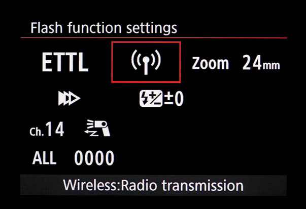
9.125
9.31Memory function
The 600EX/600EX-RT, 430EX III/430EX III-RT, and ST-E3-RT have the ability to store wireless settings for retrieval later on. This can be very handy if you’re doing a pre-planned shoot, though only one memory configuration can be stored at any given time.
To access the memory function on the 600EX/600EX-RT in master mode, press function button 4 to bring up MENU 4. Use function button 3 for MENU 3 on a slave unit. On a 430EX III/430EX III-RT, press the SUB MENU button, then use the dial to select the MEMORY option.
Once in this menu, press function button 3 (MEMORY) on a 600EX/600EX-RT/ST-E3-RT. Then press function button 1 to SAVE the current settings, or function button 2 to LOAD any previously stored settings. On a 430EX III/430EX III-RT, use the dial to select the SAVE option.

9.126
9.32Test flash (manual firing)
Pressing the illuminated “PILOT” light on the back of most Speedlites will fire a test burst, whether on-camera or not. Most flash units will fire at full power, but some have a custom function that allows for a 1/32 low-power burst instead. ![]() 9.127 and 9.128
9.127 and 9.128
Speedlites with Quick Flash/Rapid Fire have a two-color LED behind a transparent button. This button will glow green if the unit is charged up enough to fire a partial flash, and red if it’s fully charged and able to perform a full-power flash.
The pilot button is also used for waking a sleeping flash unit that’s gone into Save Energy mode (section 9.27). If the flash unit is a master wireless E-TTL device, it will command a slave flash unit to fire wirelessly. Of course, the test flash button can also be used for open flash techniques.

9.127

9.128
9.33Rear control dial
High-end Speedlites from the 580EX on have a rear-panel control dial that can be used for quick and easy control of various settings, such as flash exposure compensation. The dial is activated by pressing the center SEL/SET button. Rotating the dial changes the current settings, and pressing the center button again confirms them. The 430EX III/430EX III-RT, in fact, is completely reliant on the dial for navigating menus.
These units also have a custom function, which allows FEC to be changed by simply rotating the dial rather than by pressing the dial’s button first and then rotating it. ![]() 9.129
9.129

9.129
9.34Weatherproofing
All recent Canon professional series cameras and lenses have flexible rubber gaskets around every opening and seam. You can’t go diving with the gear—they’re weatherproof and not waterproof—but they do repel moisture, dust, and dirt.
The 580EX II, 600EX, and 600EX-RT also have weatherproofing around all seams and connections. However, while many pro-level EOS bodies are weatherproofed, only certain later cameras have a gasket around the hotshoe that can mate with the gasket on the flash unit’s foot. ![]() 9.130
9.130

9.130
Generally, Speedlite feet and gaskets work best with cameras of the same era or newer. However, sometimes rubber gaskets don’t work very well with pre-weatherproofed cameras. If a flash unit is behaving erratically, you could try removing the gasket.
With the release of the 580EX II, Canon also updated a number of flash accessories to have similar levels of weatherproofing. The CP-E4 battery pack (section 12.12.1) and the Off-Camera Shoe Cord OC-E3 both have rubber gaskets. The SB-E2 bracket (section 12.10.07) also uses the OC-E3.
9.35Flash color
The output of a flash tube is almost always slightly bluish-white in color. This is why xenon gas was chosen by flash pioneer Harold Edgerton all those years ago: the light it produces is pretty close to the color of daylight. But there are a couple of issues here.
9.35.1Automatic white balance compensation
First, the color temperature of a flash tube can vary subtly depending on its precise voltage and pulse duration. The more recent Speedlite EX flash units can monitor battery power levels and communicate with compatible digital cameras to compensate automatically for slight variations in color temperature. For this to work, the camera has to have its white balance set to automatic (AWB) or flash modes. There is no indication of this function on an external control panel—it occurs silently and automatically. ![]() 9.131
9.131

9.131
Cameras that support the feature have the phrase “Color temperature information transmission: Provided” or something similar noted in the White Balance section of their Specifications list in the manual. (See appendix C.)
9.35.2Filter holders
Second, there are often times when you’ll want to change the color of the flash completely. The only way to do this is to put a light-absorbing filter over the flash head to alter its color, as described and shown in section 7.19.3. The 600EX/600EX-RT ships with an optional holder for color-correction filters, and has special sensors to detect whether such a filter is in place. The flash unit recognizes two types of Canon filters: color temperature orange (CTO) +1/3 stop (“low”) and CTO +1 stop “high.” If the camera is radio-aware, then its white balance can be set to AWB (automatic white balance) and it will adjust automatically to the presence of the filters. If not, you’ll have to use manual white balance.
Note that the automatic system can only detect Canon-supplied filters, or third party filters designed specifically for the 600EX/600EX-RT. If you’re using a generic filter with the Canon holder, you’ll need to set personal function 05–1 to turn off automatic filter detection. The 430EX III/430EX III-RT comes with an optional clip-on amber filter.

9.132 The 600EX/600EX-RT filter sensor.

9.133 The clip-on amber filter that ships with the 430EX III/430EX III-RT.
9.36Live View, silent shooting, and flash

A camera’s Live View mode, which allows for a live display of video from the sensor chip straight to the back panel LCD (or to a TV set), can cause complications for flash on certain models. E-TTL flash metering occurs when the shutter is closed and the mirror is down because the evaluative light sensor is located inside the prism assembly. But in Live View mode, the shutter is open and the mirror is up so that the camera’s image sensor can be exposed continuously to light.
Consequently, a flash photo taken in Live View requires an extra step. The mirror must flip down so the E-TTL preflash can fire, and then the mirror must flip up again for the Live View image to be captured while the subject-illuminating flash is fired. A camera taking a flash photo in Live View mode will make two clicking noises, even though only one picture is taken.
An additional problem is the Silent Shooting mode. In this mode, the camera turns on the image sensor to begin an exposure, a technique known as electronic first shutter, rather than opening the mechanical shutter. Because of timing issues with the CMOS chip architecture, it then closes the mechanical shutter to end the exposure. However, E-TTL flash requires a preflash to be fired with the mirror up, eliminating the usefulness of an electronic first curtain shutter. For this reason, EOS cameras with Silent Shooting will disable the feature when a Canon Speedlite or compatible flash unit is attached and turned on. ![]() 9.134
9.134

9.134
Cameras with Live View Silent Shooting (see appendix C) don’t send sync commands to the PC port or the hotshoe when a non-Speedlite flash unit is used. Therefore, when using a third-party flash unit, such as studio flash, disable Silent Shooting or else the flash won’t fire.
Finally, the 500D can’t fire non-Speedlite external flash units when Live View is engaged. ![]() 9.135
9.135

9.135
9.37Cycle time and high voltage ports
Flash units work by storing up energy in a capacitor or capacitors, then releasing the power through the flash tube in a burst of light. It takes time to recharge the capacitor, a period known as the cycle (or recycling) time, and sometimes accompanied by the rising high-pitched whine of the charger. The cycle time can range from a fraction of a second to several seconds, depending on the design of the flash unit and also, in the case of battery flash units, on the power level of the last flash burst.
Most battery-powered flash units will only completely discharge (empty) the capacitors when firing a full power burst. When firing a lesser burst, the circuitry cuts off the power to the flash tube after the desired output has been achieved, thus retaining energy in the capacitor. Accordingly the cycle time will be shorter with a partial flash discharge than with a full power burst. (This is not the case with most studio flash units, which adjust flash output by power and not pulse duration.)
Many professionals covering rapid-fire events such as weddings and sports need the shortest cycle time possible. They can’t risk a lost shot while the flash ponderously recharges. Unfortunately, most Speedlites are driven by four modest AA cells—not exactly powerhouse technology. One solution is to use external battery packs to dramatically reduce the cycle time (section 12.12).
Canon equips high-end flash units with high-voltage sockets. These allow external packs to deliver additional high current directly to the flash circuitry, keeping cycle times low. However, the flash unit still needs its AA batteries to work, since the AAs also power the flash unit’s computer. The high-voltage port simply drives the flash tube output.
The 580EX, 580EX II, 600EX and 600EX-RT also have a custom function that controls whether the flash tube is fed power only from the battery pack, or from both the battery pack and the built-in AAs. The former is recommended, since recycle time is about the same either way, but the flash unit is more useful if its internal batteries aren’t drained.

9.136
9.38Remote shutter release
Why would a book on flash photography talk about triggering a camera’s shutter by remote control? Well, it turns out that some Canon Speedlites have this feature built in. What’s the point of this, especially since small remote control shutter releases are available very cheaply? Convenience, mostly. It’s just handy to be able to fire the shutter remotely using a device you already have with you. It also means, in the case of RT Speedlites, you can trigger the camera in sync with the flash if you want.
9.38.1Infrared control: 270EX II and 320EX
Most of the better consumer to midrange Canon EOS cameras since the 1990s can have their shutters fired by little handheld infrared controllers. When set to remote mode, the camera will wait for a rapid series of invisible infrared pulses from a Canon RC-1, RC-5, or RC-6 remote, and take a photo accordingly. This is a great feature for taking group shots where you want to be in the frame, or for triggering the camera without running the risk of bumping it and blurring the exposure, such as for macro photography or long exposure shots. ![]() 9.137
9.137

9.137 A Canon RC-1 pocket remote.
The Speedlites 270EX II and 320EX are compatible with this system. So, if your camera has an IR receiver, then these flash units can trigger it by pressing the remote release button on the side of the flash unit. The feature is independent of optical wireless flash. ![]() 9.138
9.138

9.138 The remote button on a Speedlite 320EX.
9.38.2“Linked shooting” radio control: 600EX-RT, 430EX III-RT
RT Speedlites can also fire some cameras remotely when used in pairs (one transmitter flash unit and one receiver). The connection between the flash unit and camera depends on whether the camera is radio-aware or not.
Radio-aware cameras can be commanded to fire if the RT Speedlite is sitting in the hotshoe (or connected via an off-camera shoe cord).
Older radio-compatible cameras cannot work in this mode, and so can’t be used with the 430EX III-RT in linked shooting mode. However, the 600EX-RT has a special socket for compatibility with older cameras. Higher-end EOS cameras have a Canon-proprietary remote control socket, known as an N3 connector for Canon cable switches. The SR-N3 adapter cable can go from the 600EX-RT to a camera’s N3 socket. (If your camera isn’t radio-aware, and hasn’t got an N3 socket, then remote control is not possible without a third-party adapter cable.)
If you’ve got a master/slave combination set up in this fashion, press function button 2 on a 600EX-RT slave unit to switch to MENU2. Then press function button 1 (REL) to take a picture on a 600EX-RT master flash unit’s camera.
To use linked shooting on a 430EX III-RT, press the wireless (![]() ) button of the group of four buttons. Turn the dial until LINKED SHOT is selected, and press SEL/SET to check the box. You can then set if the flash unit should be a master or slave unit by choosing the mode that appears beneath LINKED SHOT. Set transmission channel and wireless radio ID as normal.
) button of the group of four buttons. Turn the dial until LINKED SHOT is selected, and press SEL/SET to check the box. You can then set if the flash unit should be a master or slave unit by choosing the mode that appears beneath LINKED SHOT. Set transmission channel and wireless radio ID as normal. ![]() 9.139
9.139

9.139
To take a photo using a slave 430EX III-RT, press the SEL/SET button and select the REL option to engage the shutter release.
9.38.3Linked shooting with multiple cameras
The RT Speedlite remote shutter release feature can also trigger up to 16 cameras, including cameras attached to both master and slave flash units. The ST-E3-RT, though billed as a device for master control of remote slave units, can also act as a radio slave in this context.
The ability to fire multiple cameras is particularly useful for news gathering. If you’re a sports photographer with remote cameras stashed away in the rafters of the basketball court, behind the glass backboard, and overlooking the crowd, you can capture the moment from various angles simultaneously. Naturally, it’s best to prefocus each lens and lock it in manual focus mode, to avoid problems with autofocus “hunting.” Unfortunately, there is a slight lag time for radio control, so this feature isn’t precise enough to shoot 3D “timeslice” or “bullet time” effects.