
11 Off-Camera Flash
Goulas Ceramic Studio. Firostefani, Santorini, Greece. Courtesy ceramic artist Andreas Alefragís. On-camera 580EX as E-TTL master, set to 1/64 power in manual mode for slight foreground fill. 580EX II with full CTO gel on shelf below the seahorse, illuminating the back wall as E-TTL slave. EOS 5D Mark II, 1/15 sec at f/8, ISO 100, 55mm.
Probably the only time we see the world illuminated by a beam of light emanating from our foreheads is when we’re wearing head-mounted lamps, such as the ones on caving helmets. Headlamp lighting isn’t, it has to be said, a particularly natural way to see the world. Camera-mounted flash units, whether built-in or clipped on, inevitably produce flat and uninspiring photographs. It’s even worse when the flash unit is the main or only light source.
So the first step in improving the quality of flash photography is to get that flash off the camera. There are seven basic ways to control a flash unit that’s located remotely.
11.1The Seven Basic Methods for Off-camera Flash Control
The first way is to fire the flash manually, with no automatic control. But if you want to synchronize the flash with the camera then three methods are available: a physical cord, wireless light commands (optical), and wireless radio. Each of these methods can be used to send either sync-only commands or full metering instructions.
11.2Off-Camera Method 1—Open flash
The simplest way to trigger an off-camera flash unit harkens back to the introductory chapter and the techniques used by Victorian photographers: just fire a flash unit by hand when the shutter is open. This is “open flash,” and has no automation for either synchronization or metering. It basically means that the shutter has to remain open long enough for the flash to be set off.
For the example, in figure 11.1, a camera was attached to a sturdy tripod and the lens prefocused. The camera was set to ISO 100 with an aperture of f/5.6 and an exposure time of 30 seconds. The shot was triggered using a wired remote control to avoid bumping the camera. Exposure settings were based purely on previous experience. This is an area where light meters aren’t much help—long exposure photography is all about trial and error, as well as checking preview screens and EXIF data.
Since the photo was taken facing a pre-dawn sky under very low light, the trees essentially ended up as black silhouettes. My eye could make out details in the trunks, but the camera lacked the dynamic range to do so. Two handheld bursts from a 580EX II filtered with a half CTO filter brought out the missing detail.

11.1 Dawn over bristlecone pines. Schulman Grove, Inyo National Forest, White Mountains, California, USA. Dendrochronology (tree ring counting) has established that some gnarled and ancient trees in this grove have been growing continuously for over 4,000 years, with the oldest specimen over 4,700 years old. The sprightly young trees in this photo are a fraction of that age.
11.3Off-Camera Methods 2 and 3—Wired cords
The simplest way to control a flash unit and synchronize it with the camera is to use a physical cable between camera and flash unit. This isn’t always the most practical method, as wires can be pretty inconvenient sometimes. They tangle, restrict the range, and generally get in the way. But they fire flash units pretty reliably and are usually inexpensive.
11.4Off-Camera Method 2—Wired sync-only: PC cords
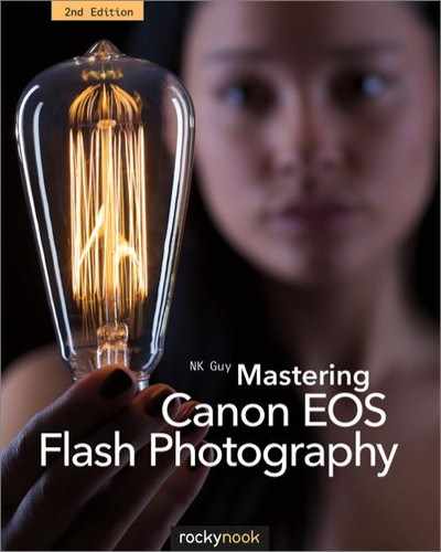
If you just want to fire a flash and don’t need automatic metering or any other advanced functions, traditional PC cords may fit the bill. These are simple electric cords that can carry a synchronized trigger signal but can’t carry metering data or any other information. In other words, they can’t be used to adjust or specify the flash unit’s power output.
The coaxial (cylindrical) design of 3.5 mm PC plugs dates back to at least the early 1950s. “PC” stands for “Prontor-Compur.” The term is derived from two brands of German-made leaf shutters used in older cameras, which is why it’s sometimes called a “German” socket. It doesn’t stand for “personal computer”: a PC cable can’t plug into a computer.
KEY POINT
Sync-only means a camera can send a simple “fire now!” command to a flash unit but can’t specify any other information, such as output levels.
Canon has never really promoted the PC cable solution, since the cords can’t support flash metering. Only high-end Speedlites have PC connectors. However, most midrange and high-end EOS cameras have PC sockets. These are intended primarily for studio flash systems, though they can of course be used with battery flash units.

11.2 This Super Ricohflex camera from the late 1950s has a simple coldshoe bracket. That small metal cylinder is a PC terminal for hooking up a flash.

11.3 A PC socket on a camera body, or the answer to the question “Why does my camera have a socket marked with a flash icon that doesn’t connect to anything I own, including my flash unit?”

11.4 LumoPro “Universal Translator.” This adapter has a foot, a hotshoe, a PC socket, and a 3.5 mm minijack, allowing it to connect to all kinds of things.
PC cables can be used on EOS cameras with no PC ports by using a hotshoe adapter, such as one shown above. These adapters take the sync signal from a PC cable and connect directly to the central point, the sync contact, on the camera’s hotshoe. ![]() 11.3
11.3
Two other issues are PC connector polarity and trigger circuit voltage. Most flash units have a positive tip and negative sleeve, but a handful of devices have the polarity reversed. Certain EOS models are incompatible with positive sleeves. And, as noted in section 10.5, some flash units have dangerously high flash trigger voltages that can damage cameras.

11.5 This studio portrait was taken using a pair of monolights in softboxes. One was synchronized to the camera using a PC cable. The other was triggered optically using a slave cell.
11.4.1PC connector problems and other sync plugs
PC connectors have a famously unreliable mechanical design, leading people to joke that the acronym should really be “Poor Connections.” The tiny friction-fit sleeve has to conduct electricity, which it does fairly well, but it also has to hold the plug in place physically, which it does quite badly. PC plugs are notorious for falling out at the slightest provocation. The problem is exacerbated when people attempt to tighten the plug by squeezing it with pliers (or even their teeth), which just worsens the poor contact by making the sleeve go out of round. ![]() 11.5
11.5
11.6
There are three approaches to the PC problem. First are plug conditioners, which are simple metal tools used to tighten and round the metal sleeve. They can mitigate damage but don’t address the underlying weakness of the plug design.
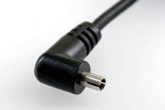
Second, there are threaded “screwlock” PC plugs that fit most PC sockets, but which also have sturdy threaded collars that hold the plugs securely in place when used with compatible screwlock PC sockets. Canon and Nikon both use the screwlock PC connector on their digital SLRs and some flash units. Oddly enough, while many devices use threaded PC sockets, the actual screwlock PC cables are difficult to find and are never included with any kits. The one shown here is from FlashZebra. ![]() 11.6
11.6
11.7 Screwlock PC plug
Finally, other sync-only plug types can be used to avoid the weakness of the PC connector.

11.8 3.5 mm (1/8") minijack

11.9 1/4" audio jack. Similar to the mini-jack, but the large size seen on full-sized headphones. These are frequently seen on U.S. and U.K.-built studio flash units.

11.10 Elinchrom Amphenol. Large sturdy connector used on some Swiss-built Elinchrom studio equipment. Reliable, but too big to be used on cameras or portable flash units.
A 3.5 mm (1/8") minijack is a mono version of the standard plugs used for the headphone jacks of mobile phones and the like. These are seen on various devices, from PocketWizard remotes (section 11.10.1) to Elinchrom D-Lite flash units (section 13.1.5). They are cheap, readily available from electronics stores, and reliable. One minor drawback is that they can short briefly when unplugged, causing misfires. ![]() 11.7, 11.8, 11.9
11.7, 11.8, 11.9
“Household” bladed plugs, with two flat blades, are the same as those used for household power in North America and Japan. They’re a very bad choice for safety reasons. It wouldn’t be a good thing for a child to plug a bladed plug into a power outlet if the other end were connected to a camera. Fortunately, these plugs are no longer common on flash units. ![]() 11.10
11.10

11.11 Household bladed plug. Terrible design seen on some older U.S.-made studio flash units.
11.4.2Speedlites and PC cables
Manual control over the flash output is needed for a PC-triggered flash unit to be useful. For this reason older Canon Speedlites are actually less useful for all-manual flash than units from other makers, since they usually lack PC sockets and sometimes have no manual output controls. Speedlites may also suffer from the SCR lockup problem described in section 11.7.6.
Though few of Canon’s flash units have PC sockets, simple and inexpensive adapter blocks that attach to the foot of a flash unit are readily available from other vendors. ![]() 11.12
11.12

11.12 An adapter that goes from a non-screwlock PC plug to a 3.5 mm minijack.
11.5Off-Camera Method 3—Wired with automatic metering: Canon flash cords
There are two extension cord systems from Canon. The first supports all automatic flash metering options on nearly all cameras, whereas the second only supports TTL for film cameras. Neither uses PC connectors. ![]() 11.13
11.13

11.13 This foot adapter from FlashZebra uses a 1/8" or 3.5 mm minijack instead of a less reliable PC connector.
11.14
11.5.1The Off-Camera Shoe Cord
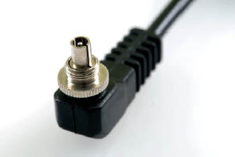
A shoe cord is a coiled extension cable that links a flash unit’s foot to a camera’s hotshoe, up to a stretched-out distance of about two feet. The cord preserves all Canon flash functions, including TTL and E-TTL. In fact, the camera actually won’t know that the flash unit isn’t sitting in the hotshoe. There have been three versions of the cord.
The first OCSC dates to the 1980s, and it just has a rotating pressure ring to keep it on the hotshoe. The flash shoe has a plastic screw socket for a regular 1/4–20 tripod bolt.
OCSC 2 adds a spring-loaded, locking hotshoe pin. The flash shoe end also has grooved sides compatible with a cold shoe, making it useful for portable umbrella setups.
OC-E3, the Off-Camera Shoe Cord 3, is basically a heavier OCSC 2 with a metal foot, a lever lock instead of a pressure ring, and a metal bushing for the tripod socket. It also has rubber gaskets that mate with those found on weatherproofed EOS bodies and Speedlite flash units.
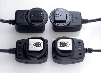
11.15 Clockwise from top left: an OCSC 2, an original OCSC, generic clone copy of the OC-E3 (note thinner cord), and a Canon OC-E3.
While an essential tool for any EOS user, the cords are fairly short, since they’re basically intended for attaching a Speedlite flash to a flash bracket. Canon presumes that longer off-camera distances will be handled wirelessly. It’s possible to connect two together for a little more distance, but Canon doesn’t recommend this since the electrical impedance changes and reliability drops. Third-party manufacturers do make compatible cords with longer wires.
11.5.2Multiple TTL flash cords for film cameras
Before wireless E-TTL, Canon sold a corded system for TTL flash on film cameras. The system uses a camera-mounted TTL Hot Shoe Adapter 3, powered by a lithium battery. 60 cm and three-meter connecting cords connect to remote Speedlites via Off-Camera Shoe Adapters (OA-2) and a TTL distributor. Each device uses a Canon-proprietary plug similar in shape to a mini-DIN connector.
Developed for the T90 in the 1980s, these cords are obsolete today. They’re expensive, lack advanced features, and work with TTL film cameras only. ![]() 11.16
11.16

11.16

11.17 Photographers often joke that asking someone to hold a flash unit is using a “voice activated light stand.” Here the model playing the paparazzo is doing just that. The camera visible in the frame is simply a prop, but the Speedlite 480EG flash unit is actually providing the bulk of the light for the scene. It’s triggered optically using the small green sensor on the back of the unit. The master flash is a 580EX II on the picture-taking camera, dialed down to 1/64 manual so it contributes relatively little light.
11.6Off-Camera Methods 4 and 5—Wireless optical control
Wires can be inconvenient, awkward, and inflexible. A studio full of cables is a trip hazard, and it doesn’t take much to send a top-heavy monolight or stand-mounted flash unit crashing to the floor. Wireless control, either optical or radio, is a great solution.
Optical devices use simple pulses of light to encode commands. Just as Boy Scouts can turn flashlights on and off to signal each other at night, optical transmitters send information to compatible receivers by brief blinks of light. The light can be visible to the human eye, or can be infrared energy that behaves just like light (except for the fact that people can’t see it) at certain wavelengths.
Unfortunately, optical devices have one significant limitation: beams of light are blocked by opaque objects and have limited distance ranges.
11.7Off-Camera Method 4—Wireless optical, sync-only: optical slaves
The simplest method to sync a flash unit wirelessly, if you don’t need automatic metering, is to use an “optical slave” light sensor. These sensors do nothing when incoming light is at ordinary ambient levels, but they respond to the bright pulse of light from a flash unit by triggering any attached flash unit.

11.18 Two low-cost optical slaves: a Hama Synchromat (left) and a Sonia slave from FlashZebra (right). The generic Hama device, available from online auctions, does not work properly with Speedlites—see section 11.7.6 on SCR lockup. The green Sonia unit is designed specifically for Speedlite compatibility. It’s the tiny device encased in clear plastic resin, shown here plugged into a hotshoe adapter. The adapter in turn fastens to the flash unit’s foot, though it can be plugged directly into any flash unit with a compatible minijack socket.
Because optical slaves react so rapidly, the triggering is effectively instantaneous. A group of flash units triggered optically can be thought of as firing in unison, though of course there’s actually a fraction of a second delay between the triggering (master) flash unit firing and the responding (slave) flash units firing. Any number of flash units equipped with optical slave sensors can be set about a scene for complex lighting scenarios. There are no limits other than budget and physical space. ![]() 11.17
11.17
Some flash units have optical slave capabilities built in. Most studio flash units, for example, have basic optical triggers. A few third party battery-powered units, such as the Sigma EF-610 DG Super, also contain optical slave sensors. No Canon E-series Speedlite has one, though an optional add-on slave sensor was sold for the Speedlite 480EG (section 9.28).
Slave sensors for battery-powered flash units are usually small plug-in devices that attach to a flash unit’s foot, a PC socket, or a similar connector. They typically don’t need batteries.
Optical slaves are a great solution for low-cost wireless triggering but do have a number of limitations.
11.7.1Line of sight and range
Optical sensors obviously have to “see” the pulse of light from the triggering flash unit. Small or medium-sized rooms, especially if they have light-painted surfaces such as walls or ceilings, are usually okay since light bounces around everywhere. But outdoors, or in large indoor venues like ballrooms, optical slaves may not respond without direct line of sight. Range depends on the sensitivity of the slave and the power output of the triggering flash unit.
11.7.2Misfires from other units
Standard optical slaves are difficult to use outside the controlled environment of the studio, since they cheerfully respond to any nearby flash unit that happens to fire. This can be a real nuisance for wedding photographers who find their carefully configured flash units suddenly going off every time Uncle Bob takes a photo with his flash-equipped point-and-shoot. There’s no way for a simple optical slave to discriminate between one triggering flash and another.
Short of banning the ubiquitous Uncle Bob, public situations like this call for wired solutions or wireless triggers with some form of digital encoding. Canon wireless E-TTL and most radio triggers are two options.
11.7.3Optical slave E-TTL misfires
E-TTL flash metering sends out a low-powered preflash for measuring light levels. Unfortunately, this preflash is usually bright enough to trigger “dumb” optical slaves. So if you use an E-TTL flash unit to trigger a dumb optical slave then either the picture will be completely dark, because the subject-illuminating flash has already ended by the time the shutter opens, or the picture will be dimly lit because only the tail end of the slaved flash unit has been recorded. The time between the preflash and the main flash firing is too brief for most flash units to recharge and trigger a second time.
KEY POINT
Simple optical slaves are not compatible with E-TTL flash.
An inconvenient workaround is to press the * (autoexposure lock/AEL) or FEL (flash exposure lock, if the camera has a separate FE lock button) button to fire the E-TTL preflash first; wait a moment, then take the photo. Since the preflash must be fired before each photo, this isn’t a very practical solution. Some optical slave units intended for use with digital point-and-shoot cameras are designed to ignore preflashes, but these are uncommon. Some sensors on more advanced studio units can also be programmed to ignore a certain number of prefires before the subject-illuminating flash.
11.7.4Disabling E-TTL on Speedlites
A better approach than using FE lock is to disable E-TTL on the Speedlite altogether. Most advanced Speedlites have a custom function or mode selector that puts the device into TTL mode only. However, not all digital cameras will fire a flash unit when it’s in TTL mode, so this may not work. Also, a flash firing in TTL mode will work as a trigger, but it might end up contributing more light to the scene than is really desired. Angling the flash head away from the scene, or putting an infrared filter (see below) over the head can help. Dialing in the maximum amount of flash exposure compensation can also work.
The best solution is to put the unit into manual flash mode and specify a low power output, such as 1/64 or 1/128. This setting should trigger the optical slave without contributing much actual light to the scene. Unfortunately, not all flash units have a manual mode. See appendix C for a list of Speedlites that can operate in manual mode.
Another option is to use a thin piece of plastic to cover the four small pins on the camera’s hotshoe. This forces the flash unit to revert to all-manual behavior, though, in this case, most will fire at full power only.
A final complication involves built-in flash. All EOS digital bodies use E-TTL for their internal flash units. Only post-2007 EOS bodies, with optional manual control over popup flash, are useful for triggering dumb optical slaves.
11.7.5Light and infrared
As noted above, sometimes you don’t want light from a triggering flash unit to actually light up the scene. Usually dialing down the output and angling the flash head away from your subject is enough, but sometimes you need a truly invisible optical slave trigger.

11.19 Prolinca (left) and a Kenro/Interfit (right) flash transmitters, both of which are basically small flash units with plastic infrared filters. They work quite well as flash triggers, though their cycle time of a second or two is slower than radio. The Kenro unit has an energy-saving sleep feature that can’t be disabled, making it annoying in studio settings.
An infrared filter installed on the flash head is the answer. Such filters are opaque black and block visible light but let infrared (IR) through. Flash tubes generate both light and infrared, and optical slaves generally detect infrared, so this trick works quite well—though at the cost of some range. In fact, commercially available optical slave triggers are nothing more than low-powered flash units with their flash tubes masked by infrared-passing filters.
Sheets of IR-passing material can be purchased from better camera stores. Failing that, sandwiching together red, green, and blue gel filters is a reasonable approximation. In a pinch, a piece of unexposed but developed slide (E6 transparency) film will work.
Infrared filters can be used on flash units that only fire at full power. However, this is rarely useful since flash units at full power take a few seconds to recharge, and the heat can cause a filter to melt or fade.
11.7.6Compatibility problems (SCR lockup)
Canon Speedlite flash units are incompatible with many dumb optical slave triggers, such as the Hama unit shown in figure 11.18. Such optical slaves can fire a Canon Speedlite only once, and then the flash unit will unhelpfully lock up. It will remain inert until it’s turned off and back on again. The problem doesn’t harm the Speedlite, but obviously limits its usefulness with optical slaves. When shopping for an optical slave device, be sure to buy one designed for Canon Speedlites, such as the green version of the Sonia slave shown.
Technical note: This is sometimes referred to as “SCR lockup” since it’s caused by a silicon-controlled rectifier (SCR) in the optical slave that’s not resetting. This appears to happen because the Speedlite’s trigger circuit does not drop to zero volts.
11.8Off-Camera Method 5—Wireless optical with automatic metering: Canon optical wireless E-TTL
Canon E-TTL’s primary innovation was improved metering over TTL, but wireless capabilities were a key feature as well.
Optical wireless E-TTL is pretty well identical to regular E-TTL from the point of view of the user, the main difference being that the control signals are sent through the air from camera to flash unit by rapid pulses of light. No wires are required, just line of sight between the devices (or reflective surfaces to bounce the light).

11.20 A small boutique in Bruges, Belgium, illustrating how available light alone can be a problem. The ceiling light fixture and window are both overexposed to allow for adequate exposure of the interior. In addition, the room in which the camera is located, visible to the right side, is not as brightly lit as the main room. EOS 5D, 1/6 sec at f/4, ISO 100, 24 mm.

11.21 This photo is lit by an on-camera 580EX master flash unit that has its head angled to the ceiling. This illuminates the belts on the wall to the right and controls the slave unit. The 420EX slave is positioned in the other room, camera left. In addition to improving the interior lighting, the use of flash permits a lower overall exposure setting, bringing the outside to a more reasonable level. Note one drawback: the belts to the right and the bags on the top right shelf have some unfortunate flash shadows. EOS 5D, 1/8 sec at f/8, ISO 100, –1 FEC, 24 mm.
The simplest technical comparison is a TV remote control. In the case of TV remotes, small infrared (IR) LEDs send rapid-fire, digitally encoded pulses of invisible energy bouncing around the room. A receiver built into the TV set receives the signals, decodes them, and responds accordingly, perhaps by changing channels or muting the volume. In other words, the remote can be used to send a variety of different instructions to the TV set, not just “turn on now.” The fact that the remote transmits invisible IR energy and not radio waves is easily demonstrated by simply putting a finger over the LED or panel on the remote’s front to interrupt the signal.
Flash units are conceptually similar, but instead of infrared LEDs, ordinary xenon flash tubes are used to produce rapid-fire bursts of digitally encoded light. These precisely timed pulses can be interpreted by fast-reacting computers and decoded, sort of like Morse code. The preflashes instruct the remote flash units when to fire and at what brightness. In other words, both sync and metering are fully supported in a transparent way.
Camera manufacturers are the primary makers of these light triggers for flash units. Canon, Nikon, Sony, Olympus, and Pentax all sell incompatible, but technologically similar, light-based flash controllers in their SLR lineups. Canon’s system, known as optical wireless E-TTL, is built into most Speedlites sold today.
11.8.1How optical wireless E-TTL works
Canon’s optical wireless system requires at least two flash units. A master flash unit is attached to the camera, and any number of slave flash units are set up to illuminate the scene as desired. Post-2007 EOS models can also use their built-in flash units to command remote slaves.

11.22 An EOS 5D equipped with a 580EX II serving as a master Speedlite. The master sends control signals to the two slave units in the front. Note how the flash heads on the slaves are rotated 180° so that the wireless sensors on the fronts of the units face the master.
As a side note, it has long been a convention in engineering circles to refer to a device that issues commands as a “master” and a device that receives such commands as a “slave.” This unidirectional design is in contrast to a “peer-to-peer” model in which either device can send or receive commands. Obviously the words “master” and “slave” have regrettable historical meanings. But, since Canon and other manufacturers use these terms, they’re used in this book in place of other popular synonyms (e.g., commander/remote, transmitter/receiver, etc.).
Many EX series units can serve as a master, which has to be electrically linked to the camera. This can be done either by putting the flash unit into the camera’s hotshoe or by using an Off-Camera Shoe Cord that transmits the necessary computer data (section 11.5.1). EX macro units can also serve as masters, though only under special circumstances as described in “Macro ratios” (section 11.8.6). The master unit can be told to contribute light to the scene, or it can be set simply as a controller unit. There’s also the Speedlite Transmitter ST-E2, a special master-only unit that lacks a scene-illuminating flash tube and only works as a flash controller.
Most EX units sold today can serve as a slave. A number of flash units built by third-party manufacturers are also compatible with Canon’s wireless system. The remote units must be set to slave mode, in which their front-mounted optical sensors dutifully sit and wait for pulsed signals of light from the master unit. The commands are so rapid that, to the human eye, they look like a single brief flash, but in fact complex messages and instructions are sent out. Virtually every standard E-TTL function is supported wirelessly through these control commands. One notable exception is second curtain sync.
There’s no limit, other than physical space and your budget, to the number of optical slaves that can be used. No two-way communication occurs between master and slave units. Each slave simply responds to commands, and the master only knows what slave units exist in terms of whatever light they produce during the prefire stage.
To be really useful, Canon’s optical wireless system needs an E-TTL camera. When used with older type B film cameras, Canon wireless flash works sync-only but can’t support any form of automatic flash metering, including TTL or A-TTL.
11.8.2Line of sight
Optical wireless E-TTL is ideal for quick, portable, and flexible flash setups in smaller spaces. However, optical signals have two significant restrictions. First, light signals are thwarted by walls, tables, people, and other opaque barriers. Second, the range is limited; flash units can’t be triggered remotely from great distances, such as from the other side of a stadium or even across a large ballroom.

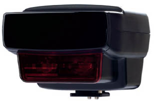
11.23 The dark panel above the Canon logo on this 430EX II conceals the wireless flash sensor.
Each slave must be positioned so that the wireless sensor on its front can see the master’s signals, either directly or reflected. When shooting indoors with many light-reflecting surfaces (walls, ceilings, etc.) a slave can often detect a master’s control signals even if the two units aren’t set up to point at one another. But outdoors or in a non-reflective indoor setting (vast ballroom, black-painted nightclub, coal mine, etc.), the slave’s sensor must be able to see the front of the master.
The sensor is behind a dark plastic cover on the front of the unit’s body. Slave-capable flash units have rotating heads, so you might need to turn the flash head so that it points in a different direction from the body. The master unit can also be put on an off-camera shoe cord rather than directly onto the camera body if necessary. Each slave must see the master directly, and there’s no capacity for relaying with intermediate devices.

11.24 This photo of Kikunoya guest house in Kanazawa, Japan, is lit by available light only. The garden is lit by sunlight, and the room interior is lit by fairly low tungsten light.

11.25 The same scene as in figure 11.24, shot with an ST-E2 as an on-camera master and a 420EX as a slave. The 420EX was on the other side of the right-hand screen in the hallway area, but enough of the ST-E2’s control signal passed through the shoji rice paper screen to trigger it correctly.
There’s a common misconception that optical wireless E-TTL masters transmit invisible infrared signals, like the aforementioned handheld remotes used to control TV sets. This actually depends on the master unit used. All EX series master units, such as the 580EX or the MT-24EX, pulse their subject-illuminating flash tubes to send commands, so they produce both white light and IR. However, the ST-E2 master-only unit (section 9.7.7) transmits discreet invisible infrared only.
Command transmission distance depends partly on the angle at which the master is transmitting relative to the slave, whether the signals are direct or are bouncing off surfaces, and which master unit is used. EX units, with their powerful flash tubes, have a greater transmission distance than the tiny ST-E2.
11.8.3Optical wireless channels and groups
There are four different data “channels” for flash control, and each slave unit can also be put into one of three “groups,” sometimes referred to as “slave IDs.” The numbered channels (1–4) allow up to four cameras to use wireless E-TTL in the same physical location without conflicting with each other. They’re named by analogy to radio or TV channels but don’t actually use different transmission frequencies—each slave detects all incoming commands, but only responds to those on the channel to which it’s set.
You usually don’t want all your slave units to fire at precisely the same power or output level. Thus the three groups or slave IDs (A through C) permit independent flash output ratios to be specified within a given channel when used by most cameras. In other words, all slave flash units set to the same channel will always fire simultaneously. But the different groups allow finer control over the units by letting you specify relative brightness of the flash units in the groups. For more information, see the next section on ratios.
You can check whether or not the slave units are within transmission distance by pressing the test (“pilot”) button on the master flash unit. The camera will instruct all the slave units to emit a flash of light in sequence. First the A group units will flash, then B, and then C. If the camera has modeling flash capabilities (section 9.24), then a quick preview of the final scene can be viewed.
11.8.4Wireless E-TTL ratios
As noted earlier, there’d be no point in being able to control multiple groups of flash units if they all fired at the same power level anyway. Consequently, most E-TTL capable cameras can specify the output levels of up to three separate groups of remotes—or five when using radio wireless E-TTL (section 11.11.1).
The primary means of control is the ratio of light produced by groups A and B. Confusingly, this A:B ratio can be set from 8:1 to 1:1 to 1:8 in half-step or third-step increments, for a total of 13 steps or a 6-stop range (e.g., 1/8 of the light is –3, stops and 8× the light is +3 stops). More specifically: 1:1 means both A and B groups fire at the same power; 8:1 means that the group A units put out much more light; and 1:8 means that the group B units put out much more light.

11.26
If a Speedlite EX unit is the wireless master, then its internal flash tube defaults to group A. To control the ratio of slave unit output to master unit output, be sure to put the slave units into group B. Note that wireless flash ratios are unrelated to fill flash ratios between flash and ambient lighting.
EX master units can also specify flash compensation for a third and completely independent group: group C. Group C units don’t fire unless the ratio setting has been set to “A:B C.” Unlike A:B ratios, compensation of group C is adjusted from –3 to +3 stops relative to the A:B ratio, in third-step increments. Group C can’t be adjusted relative to group A or B only, since it’s assumed that group C is used primarily for background lighting. Unfortunately the ST-E2 can’t control group C.
The earliest type A (E-TTL capable) film cameras don’t support wireless E-TTL ratio control, and all flash units on the same channel will fire at the same power. When using a 500/600 series unit as a slave, there is a partial workaround: flash exposure compensation can be specified manually using the flash unit’s controls.
Regrettably, unlike radio E-TTL, optical E-TTL doesn’t let you set exposure values for each group or turn specific groups on and off. Automatic control is restricted to ratios, an A:B ratio and a compensation for C separately. This system assumes a main, fill, and background flash lighting model, making it a somewhat restrictive system. The new radio system offers much more flexibility over each group (section 11.11.1).
11.8.5Manual wireless E-TTL control
Although the ratio system is limiting, optical wireless E-TTL does permit manual control. To access it, press and hold the MODE button on the master unit until M appears. It’s now possible to control slave flash units manually by dialing in the desired power output, such as 1/4 or 1/16. This will instruct all slave units to fire at whatever power output they produce for that fractional setting. This technique doesn’t work very well with flash meters, since they tend to be confused by the optical wireless commands, but it works well when using digital preview screens to check the results.
You can also control the three groups separately using manual control. Put the master unit into M mode, then select the RATIO option as described above and choose A:B:C. The flash output power for each of the three groups can now be specified manually, though of course it’s technically not a ratio at all. This system lets you set arbitrary power output levels for each of the three groups (e.g., fire group A at full power, group B at 1/2 power, and group C at 1/8 power).
11.8.6Macro ratios
The MR-14EX, MT-24EX, and MR-14EX II macro units can serve as master units in wireless E-TTL setups, though not in the way you might expect. One of the two flash tubes on the macro head is assigned to group A and the other to group B (the tubes are labeled). The controls on the flash unit controls the output ratio between the two tubes when used with a ratio-capable camera. You can also make just one tube fire, if you want. Figures 11.28 through 11.33 demonstrate different setups using the MR-14EX (the Mark II version is identical in this context) and the MT-24EX.

11.27 The Speedlite MT-24EX has two separate flash heads, which can be positioned independently or clipped to the end of a macro lens, for flexible closeup lighting control.
Magnesium refining can produce strange-looking crystal nodules as seen here. This lightweight metal is used to build many modern EOS cameras.

11.28 A Speedlite MR-14EX set to a 1:1 ratio. This means both tubes fire at the same level, for flat and even lighting.

11.29 The MR-14EX set to an 8:1 ratio. Left-hand tube A is 3 stops brighter than right-hand tube B. (4:1 would be 2 stops brighter, and 2:1 would be 1 stop brighter.)

11.30 The MR-14EX set to a 1:8 ratio. This is the reverse of the previous example, with tube B brighter than A.

11.31 Here the MR-14EX is firing normally, but with group C enabled. A 580EX II slave is firing through a clear red plastic cup behind the nodules.

11.32 This shot was lit with an MX. Its movable flash heads were positioned far to either side, giving a more sculpted look.

11.33 An MT-24EX with group C enabled and the same 580EX and cup arrangement as 11.31.
Slave flash units are assigned to group C, so that flash exposure compensation of the slaves can be set relative to the two macro unit tubes, an ideal situation for background illumination of macro shots. A custom function on the flash unit can be set to assign slave units to groups A and B, but then their output is linked to the internal tubes.
11.8.7Speedlite Transmitter ST-E2
The ST-E2 is a tiny hotshoe-mounted flash unit with a normal flash tube on the front. But the tube has a black plastic filter, so that visible light is blocked and only invisible infrared energy shines forth. The ST-E2 uses this IR output, carefully pulsed in coded sequences, to send wireless E-TTL commands to slave Speedlite flash units. Much smaller than any other master Speedlite device, and powered by a 2CR5 non-rechargeable lithium battery, it’s more discreet in operation than a normal visible-light flash unit when controlling slave units. ![]() 11.34
11.34
11.34 Speedlight Transmitter ST-E2.
Conveniently, it has red autofocus assist LEDs on the front, and a simple pushbutton system for controlling A to B flash ratios on the back.
Unfortunately, the ST-E2 has serious drawbacks and it hasn’t been updated since its introduction in 1998. The ST-E2 can’t transmit its control signals as far as the 500–600 series units, and its coverage angle is narrower as well, making it useful only in medium-sized rooms. The ST-E2 supports groups A and B with A:B ratio control and, mysteriously, it can’t control group C. Other missing features include flash exposure bracketing (FEB), flash exposure compensation (FEC), and control over manual or stroboscopic slave units. 500–600 series units are larger and more expensive, but are also much more capable E-TTL master units.
11.8.8Speedlite Transmitter 90EX
Optical wireless E-TTL was considered an advanced feature when it was introduced, but Canon has gradually been migrating it down the product lineup, especially now that radio wireless E-TTL is the new high-end. Canon sells a tiny master-capable Speedlite, the 90EX, which is too weak to be a very good on-camera flash unit, but which serves as an optical wireless master. When used with a digital camera with menu control, it even provides full ratio control and manual flash output. In a sense the 90EX can be seen as an affordable replacement for the ST-E2, albeit one that lacks red autofocus-assist lights.
The 90EX, and small slave-capable units like the 270EX II, mean you can have a full wireless camera system for cameras that lack master control via popup flash—even with small bodies like the EOS M3 mirrorless camera shown here. ![]() 11.35
11.35

11.35 An EOS M3 mirrorless camera with a 90EX master. Two Speedlite 270EX II units serve as wireless slaves.
11.8.9Popup flash master/integrated Speedlite transmitter
Since 2009, Canon has brought to its lineup the use of the popup flash to command slave flash units (section 9.18). By going to the camera’s external Speedlite menu (ESC, section 9.30) you can enable fairly advanced flash features with the popup, including wireless master and manual control.
11.8.10 Third-party support for optical wireless
A number of companies make equipment that’s compatible with Canon’s optical wireless E-TTL.
Quantum QNexus
Quantum makes add-on QNexus modules that can interpret optical signals intended for Canon wireless E-TTL units, and that can translate them for the company’s Qflash series of battery flash units. All E-TTL functionality, with the exception of high-speed sync flash, is supported transparently. From the camera’s point of view, a QNexus-connected flash unit is just another Speedlite, albeit one that can pump out a lot of light. The usual groups and channels can be specified. ![]() 11.36
11.36

11.36
Qflash units are high-output flash units powered by battery packs. They bridge the gap between Canon Speedlite-type units powered by AA cells and the big studio flash units powered by battery packs the size of car batteries. This makes them ideal for wedding photographers and other professionals who need lots of light in a reasonably portable fashion. Although Qflash units lack zooming flash heads, they have glass-encased tubes to which a wide variety of light-modifying devices, such as reflectors and softboxes, can be attached.
Sigma
Sigma produces flash units that have optical wireless functions compatible with Canon’s. They support the same four channels and groups as Canon, though Sigma calls the groups 1, 2, and 3 rather than A, B, and C. Ratios and other features are also fully supported.

11.37 The Sigma EM 140 DG macro flash in wireless mode.
The EF-610 DG Super can operate with Canon wireless E-TTL as both a master and a slave unit. The EM 140 DG macro flash can operate as a wireless E-TTL master. The EF-610 DG ST doesn’t support wireless E-TTL.
The EF-610 DG Super is an affordable alternative to Canon units. However, wireless operation is somewhat difficult due to the DG Super’s confusing user interface, and it occasionally yields inconsistent metering.
Some Metz flash units are compatible with optical wireless E-TTL, though the company also has its own wireless system that isn’t compatible with Canon’s. The units that support optical wireless E-TTL are generally “System Flash” units.
11.8.11 Drawbacks of optical wireless E-TTL
Wireless E-TTL is a useful basic system but is not without its drawbacks. By far, the biggest problem is line of sight and range. Outdoors, in dark-painted rooms, in huge rooms such as theaters or hangars, or in situations where there’s powerful backlight from the sun, wireless E-TTL simply doesn’t work very well, especially when compared to radio systems.
The ratio system for the three wireless flash groups is also not very useful. First, it’s confusing because groups A and B are controlled as ratios to each other, whereas group C is controlled with exposure compensation over the combined A+B groups. Second, there’s no way to simply specify the output of each group in EV or other units, and there’s no way to turn specific groups on or off. These issues were all addressed when radio wireless E-TTL was developed.
11.9Off-Camera Methods 6 and 7—Wireless, radio frequency (RF)
The most reliable way to transmit flash-triggering information wirelessly is by radio frequency (RF). There are a number of reasons why most professionals rely on wireless flash control that employs radio commands.
11.9.1No line of sight requirement
The primary advantage is that radio signals can pass unhindered through many visually opaque barriers, and so are immune to the line of sight and distance limitations imposed by optical systems. That doesn’t make them invulnerable; signals can be blocked by metal objects, or at certain frequencies, by water-filled objects such as plants or people. Dense materials such as stone walls or stucco walls with embedded metal mesh can present a barrier. Other nearby devices transmitting on the same frequencies can also interrupt a signal.
But in most cases, radios can transmit signals to flash units on the other side of walls, tucked around corners, hidden behind backdrops, and so on.

11.38 Dysert O’Dea Castle, County Clare, Ireland. This is an example of a situation where radio control works well. The room was lit by a single 580EX II, with ambient exposure lowered so that the view out the windows wouldn’t be entirely blown out. Wireless E-TTL with a 580EX master couldn’t trigger the slave flash unit, since it was positioned around the corner in another room, so a radio trigger was used.
11.9.2Enhanced range
RF controllers can usually work over greater distances than optical controllers, though the range obviously depends on the product and general conditions. Advanced professional RF units such as non-TTL PocketWizards can work up to 1,500 feet in open air, though cheap products might have a range of only around 30 feet. Professional RF transmitters hold great benefits for sports photographers who need to trigger large flash units at the other side of a hockey arena, or wedding photographers who want to trigger flash units in a large ballroom for a couple’s first dance.
Note one unintended consequence of using radio to control E-TTL devices: with optical wireless E-TTL, it’s usually not possible to control a flash unit that’s so far away that the camera’s evaluative metering can’t see the unit’s preflash. But with radio signaling it becomes entirely possible. This isn’t an issue when controlling remote flash units sync-only: if they’re within radio range, the flash units will fire at whatever output level is specified.
Note also that it’s wise to interpret the manufacturer’s published range somewhat conservatively. Like fuel economy ratings for cars, transmitter range numbers are often somewhat optimistic in nature.
11.9.3Digital coding
Most RF systems use some form of digital coding in their transmissions. This serves two functions. First, digital coding can reduce the risk of misfires caused by random radio noise. Very simple low-cost transmitters may transmit uncoded triggering commands, or may support just four different pulse-modulated commands. Such systems can be fooled by bursts of radio static, whereas more expensive transmitters employ digital error correction to ensure that an incoming signal is genuine. This is one of the reasons why cheap transmitters can misfire—they’re more vulnerable to accidental triggering by noisy radio devices in the vicinity.
Second, most flash transmitters send coded signals (much as a garage door opener is coded for security) so that more than one transmitter of the same brand can operate in the same area. They may also transmit on different radio frequencies, again reducing the risk of misfires caused by signals from other compatible devices. ![]() 11.39
11.39

11.39 Tiny slide switches used to specify security coding on a transmitter.
But even professional devices have a finite number of channels or codes available, making conflicts more likely in busy areas or when using a device with great range. Sports or political photographers covering a big event, for example, may find their flash units firing inadvertently when another photographer is shooting. Well-organized professionals covering an event may actually sit down and allocate channel or code numbers to each other in advance to avoid this problem.
11.9.4Multiple receivers
Many radio systems, though not Canon radio wireless, support any number of receivers. When such transmitters broadcast a signal, any receiver in range that is programmed or designed to respond will do so. A single transmitter can control complex studio setups with dozens of flash units. Canon’s radio wireless is an exception, with a maximum of 16 devices at once.
11.9.5Regulatory issues
The biggest drawback of radio is that the signals have a habit of wandering off wherever they want. They don’t respect walls or arbitrary human barriers, and they can interfere with other devices. The radio spectrum is a finite natural resource and is highly regulated by governments.
Governments don’t want imported products that can interfere with local radio products, especially when radio frequencies used by emergency services are involved. But many frequency bands are allocated to different functions across the world. Local laws can mean a device permitted in one country might not be legally imported, sold, or even used in another. ![]() 11.40
11.40

11.40 Regulatory approval logos for the FCC (USA), Conformité Européene (Europe), VCCI (Japan), ACMA (Australia), and Industry Canada.
This lack of regulatory coordination explains the variety of incompatible devices available in different markets, a frustrating problem for the traveling photojournalist. For example, U.S. FCC PocketWizard transceivers operate on a different frequency range than European CE models. A U.S./Canada RadioPopper PX uses the same frequency range as GSM-900 cellphones elsewhere in the world, and so is illegal to use outside North America.
The easiest solution has been to adopt the same 2.4 GHz radio band used by Wi-Fi computer networking and Bluetooth devices. Canon radio wireless E-TTL, Elinchrom Skyports, and Paul C. Buff CyberSyncs all use 2.4 GHz. The main disadvantages are that 2.4 GHz is packed with competing devices and has a range limit compared to lower frequency signals.
11.9.6Latency
Radio triggers often advertise a very high maximum shutter speed that isn’t always achievable. Sometimes this is because of the X-sync problem with all SLRs, in which case the maximum shutter speed is going to be determined by the camera. But in other cases the flash transmitter itself introduces signaling delays, something engineers call latency.
In other words, it can take a fraction of a second for the transmitter to take the signaling information and broadcast it, and then for the receiver to decode it. This delay can be long enough to lower the maximum shutter speed. It’s worth testing any new product to find out what its real-life values are going to be.
11.9.7No cross-manufacturer support
There are no universal standards for radio trigger communications, so a product made by one manufacturer probably won’t work with a product made by another. The investment in a given product line isn’t always transferrable.
Occasionally, companies will license another firm’s technology—such as Profoto and Bowens flash units, which support PocketWizard receivers, and some companies make clone products compatible with Canon’s radio signals—but this is not the norm. In fact, sometimes two radio products made by the same manufacturer won’t work together.
11.9.8Battery drain while idling
Transmitter batteries are usually small and last a long time because most transmitters only send brief bursts of commands when a photo is taken. Receivers, on the other hand, have to sit and wait for incoming commands, and therefore require larger batteries.
11.10Off-Camera Method 6—Radio, sync-only
A whole host of companies sell radio frequency (RF) transmitters that can be used to sync off-camera flash units but that don’t offer any metering capabilities.
The LPA Pocket-Wizard system is probably the best-known product line in North America, whereas in Europe the Elinchrom Skyport and Bowens Pulsar systems are popular. Other radio remotes of note include Microsync Digital, Cactus, AlienBees/Paul C. Buff CyberSync (not discussed in this book), and Yongnuo.

11.41 When using sync-only radio transmitters, there are three basic ways to adjust exposure. If time isn’t an issue, just run back and forth and adjust flash output manually. If depth of field isn’t an issue, adjust the aperture. If noise isn’t an issue, adjust ISO when shooting digital.
11.10.1 PocketWizard
The PocketWizard system has long been the studio professional standard for radio remotes in North America. The transceivers, while expensive, have a reputation for solid reliability and long operating ranges. PocketWizards have error detection systems to avoid misfires and are rated at distances up to 1,600 feet in open air, which is enough for a vast sports arena or Olympic venue.

11.42
The classic PocketWizard sync-only devices are black plastic boxes, about the size of a deck of cards, that attach vertically to a camera’s hotshoe. The company’s flagship for years was the classic MultiMAX, which was a sophisticated device with an LCD panel. ![]() 11.43
11.43
The modern Plus III model is auto-switching and decides whether to transmit or receive based on what device it’s plugged into. If it’s on a camera’s hotshoe, it will transmit a sync signal when the shutter is fired. If it’s attached via a cable to a flash unit, it’ll receive the radio signal and trigger the flash unit. It supports four different digital channels and can also be used to fire cameras remotely. This latter function is popular with sports photographers and photojournalists, who sometimes hide remote cameras in interesting or inaccessible locations for unusual shots. The PocketWizard Plus X is the less expensive cousin. ![]() 11.44 and 11.45
11.44 and 11.45

11.43

11.44

11.45
Conveniently, other companies produce receivers compatible with Pocket-Wizard signaling, making it a useful product ecosystem. Profoto and Bowens both make optional add-on units that transform some of their studio flash units into PocketWizard devices. This saves the trouble of external boxes, cabling, and separate batteries for the receiver. Sekonic also sells light meters with built-in PocketWizard-compatible transmitters, making it easy to walk around a set lit by remote-operated flash units and test the lighting.
The primary drawbacks of the PocketWizard sync-only devices are cost, size, and complexity. They’re fairly large and have a tall vertical orientation, which blocks sight over the top of the camera. ![]() 11.46
11.46

11.46
There are also different versions produced for different markets. As described above, these versions transmit on different radio frequencies and are therefore incompatible.
In short, PocketWizards are a professional studio basic. They work well for any situation in which reliable radio sync, but not metering, is required.
11.10.2 Elinchrom EL Skyport
Swiss studio flash manufacturer Elinchrom produces a line of portable radio triggers for its flash units. They come in two forms: the EL Skyport Universal, which can perform sync-only triggering with almost any make of flash unit; and the EL Skyport RX, which can also adjust the power output of Elinchrom RX studio flash units. ![]() 11.47
11.47

11.47 Three EL Skyport devices: the Skyport USB Transceiver, the Skyport Transmitter, and the Skyport Universal Receiver. Not included: the advanced Skyport Plus HS transmitter, shown in section 13.6.3.
EL Skyport Universal
The Universal models are sync-only radio triggers that consist of transmitter / receiver pairs operating at 2.4 GHz, the same radio frequency used by Wi-Fi personal computer networks. They support eight different frequencies and have an official open-air range of about 400 feet. Digital error correction is supported. The transmitters attach directly to a camera’s hotshoe and are powered by a small lithium button cell. They’re very small, low-profile devices that don’t block the view over the top of the camera.
The receivers are powered by an integrated rechargeable battery pack, like a mobile phone, for about 24 hours of use on a single charge. They also have auto power-off after a number of hours. On the one hand, the built-in battery means no batteries to throw away or lose. On the other, it means that it isn’t possible just to replace the battery on a shoot if it runs out unexpectedly. Still, the receiver can continue to function while it’s recharging.
Four different groups are supported, and the transmitter can fire specific groups or all groups at once. This allows for different lighting setups to be configured and tested.
The RX-capable Skyports add the ability to transmit power output information, though only to Elinchrom RX studio flash units. They are not able to handle automatic TTL-style flash metering—they simply enable the photographer to perform manual output control wirelessly, in 1/10 stop increments, without the bother of walking over to each flash unit. In this, they excel. The ability to adjust the output of multiple flash units right on-camera is great time saver in the studio. It also makes it easy to adjust the power output of a monolight in an inaccessible location, such as on a high lightstand or on a boom.
The RX system also has a version with a computer USB interface. This transmitter plugs into a Mac or Windows computer and comes with downloadable software that supports a wide range of controls. Intended for professional studio settings, the software can store commonly used settings and configurations for later retrieval. ![]() 11.48
11.48

11.48
While versatile and useful, the advanced functionality of the RX units doesn’t work with any flash units other than Elinchrom RX devices. But in a studio equipped with compatible units, the ability to adjust multiple flash units directly from the camera is extremely handy.
11.10.3 Bowens Pulsar
British flash manufacturer Bowens sells hotshoe-mounted radio transceivers known as Pulsars. Each transceiver can transmit (TX) or receive (RX) sync commands at 433 MHz, depending on the position of the power switch. The devices run off two ordinary AAA cells, though a power socket is available for continuous studio use. They’re oriented horizontally and so block less of the view along the top of the camera. ![]() 11.49
11.49
The transceivers have two output jacks, one PC and one 3.5 mm minijack. The PC socket is used for flash sync, and the minijack is used for firing a flash unit or for triggering a camera’s shutter release.

11.49
One useful feature of the Pulsar is its ability to handle multiple channels simultaneously. Up to four separate channels can be enabled and triggered independently, and an “all” setting lets a transmitter fire any device on any of the four channels at once. This makes it very useful for testing flash ratios and the like. The Pulsar can also transmit on any one of five separate frequencies via a switch labeled “Studio.”
Another advantage is that small radio receivers can be installed in many newer Bowens studio flash units. These don’t run off battery power and can’t be lost, making them a very convenient radio triggering solution for Bowens users. As with the stand-alone transceivers, the built-in receivers support sync-only.
11.10.4 Microsync Digital
One of the smallest radio solutions is the Microsync Digital from U.S. camera bag maker Tamrac. This is a transmitter / receiver pair that operates on 433 MHz. The transmitter is an incredibly tiny unit that sits in a camera’s hotshoe, powered by a lithium coin cell. The receiver is larger, as it accommodates two AA cells. ![]() 11.50
11.50
There are actually two models of the receiver, both geared to the North American market. One has a large 1/4″ plug and the other a two-bladed “household” plug. These plugs allow the receivers to be plugged straight into many North American studio flash units. Adapter cables are required if a given flash unit doesn’t have these two connectors. The cables can be a little bulky, since both 1/4″ plugs and household plugs are large. Note the safety risk of the bladed version. Keep it well away from children, since the bladed receiver could be plugged straight into a power socket.

11.50

11.51
The Microsyncs do not have any advanced features, such as the ability to transmit on multiple channels for ratios. They also cannot sync at shutter speeds higher than about 1/180 sec.
Only four channels are available, and channel selection on either device is awkward. The transmitter has a tiny hole in the side, into which a bent paperclip must be inserted to cycle through the channels. The receiver will sync itself to the transmitter if the paper clip is pushed in within 10 seconds of powering on the receiver. In a studio setting where the channel is rarely changed, this shouldn’t be a problem. However, photographers who shoot in the field might find it an issue. ![]() 11.51
11.51
The Microsync’s primary selling point is the extremely small transmitter. The product is basically optimized for a small studio setting where channels are infrequently changed but an unobtrusive flash sync solution is needed. It’s less suited for photojournalist or field use, particularly if battery-powered flash units are used.

11.52
11.10.5 Quantum FreeXwire
U.S. flash manufacturer Quantum offers a number of radio solutions for remote triggering. The simplest is the Radio Slave 4i, which is a basic sync-only radio transmitter. A more advanced system with eight separate channels is the FreeXwire system. This can support full-metered TTL commands also transmit sync-only signals. ![]() 11.52
11.52
The basic FreeXwire Digital Transmitter can be fastened directly to the camera’s hotshoe with the FW12 hotshoe adapter. The FW12 doesn’t, unfortunately, support TTL signals in any way, so it doesn’t take full advantage of the transmitter’s capabilities. However, it is simple to use.
The FW9T transmitter, powered by a pair of AAA cells, sends radio commands at 434 MHz to a compatible Quantum receiver on a Qflash battery flash unit. ![]() 11.53
11.53
The Quantum system includes other devices as well. For example, in addition to a FreeXwire receiver, there’s also a transceiver that can serve as either a transmitter or receiver, and that can actually extend the range of a signal by acting as a repeater. The Quantum system is extremely versatile, but also difficult to understand because of the vast range of products and all their permutations.

11.53
11.10.6 Cactus / Gadget Infinity V2 / V2s / PT-04
These simple units from Hong Kong’s Gadget Infinity were widely available from Internet auction sites, sold under different brand names, and were one of the big kickstarters in expanding the wireless flash trigger market. They were dirt cheap, and marketed to students and other beginners on tight budgets. People often jokingly called them “poverty wizards.” ![]() 11.54
11.54
The set consisted of two devices: a shoe-mounted transmitter and a clip-on receiver. The transmitter was powered by a small 12-volt battery of the type commonly used in household smoke alarms. The only other features were a single test firing button, a 3.5 mm minijack socket, and two tiny DIP switches for setting one of four codes.
The receiver was a rectangular box fastened to the shoe of a flash unit. It was powered by a non-rechargeable lithium CR2 battery—an expensive choice since receivers must be left on for extended periods, waiting for incoming transmissions. It had a crude metal bracket, tilt-adjusted by a fragile thumbscrew, for attachment to a tripod or cold shoe. The receiver also had a PC socket and a transmission confirmation LED.

11.54
These and other low-cost triggers radically transformed the remote flash market by making the devices affordable to a broad audience. Admittedly, they frequently failed to fire, were pretty flimsy and easily broken, and had a really limited range. But then they were never intended to be reliable professional products.
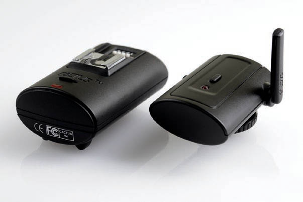
11.10.7 Cactus / Gadget Infinity V4
The V4 is another hobbyist product but a significant improvement from the V2 design. The units have four DIP switches for a total of 16 different codes. ![]() 11.55
11.55
Although they transmit on the same 433 MHz frequency band as their predecessors, the increased number of codes means they are not compatible with the V2 line. Anyone upgrading to the V4 will have to abandon the previous devices. Since the V2 devices aren’t all interchangeable anyway, this may not be an issue.
The transmitter has a swiveling, albeit delicate, antenna and some cosmetic changes. The receiver has the biggest improvements. First, the weak rotating bracket is omitted since the device is now a simple base upon which the flash unit rests. It also operates on a pair of ordinary AAA cells, which are cheap, widely available, and made in rechargeable versions. Range is extended and officially goes up to 100 feet in open air.
11.55

11.56 One advantage of inexpensive technology: here, a group of old industrial ovens is lit by separate flash units, each controlled by a low-cost flash trigger.
KEY POINT
Most inexpensive flash triggers are not compatible with each other. Even similar products from the same maker may be incompatible, and new products come and go on the market all the time. The ones listed here are just a handful of those available. Keep this lack of compatibility in mind if your goal is to build up an investment in your gear!
The receiver has a couple of practical limitations. First, the on/off switch is blocked by the front edge of many flash units, meaning that the flash unit has to be removed to turn off the receiver. This, and the fact that the switch position is hard to see, makes it likely that the unit will be left on inadvertently, draining the batteries. Second, the receiver isn’t wide enough to serve as a reliable stand, though it can be loosely attached to a normal Speedlite clip-on stand for better stability. The battery door also tends to fall off.
The V4 lacks the reliability and range of the high-end professional products, but then it doesn’t really compete with them.
11.10.8 Phottix Ares
The 2.4 GHz Phottix Ares is another inexpensive flash trigger, but sturdier and more reliable than the really cheap ones.
It comes in receiver/transmitter pairs, and can operate on one of eight channels, with the option to fire all channels. The transmitter is on a swiveling mount, and so can be horizontal or vertical. The product has a decent range, with an advertised range of 650 feet/200 meters, and the units run on two AA cells.

11.57
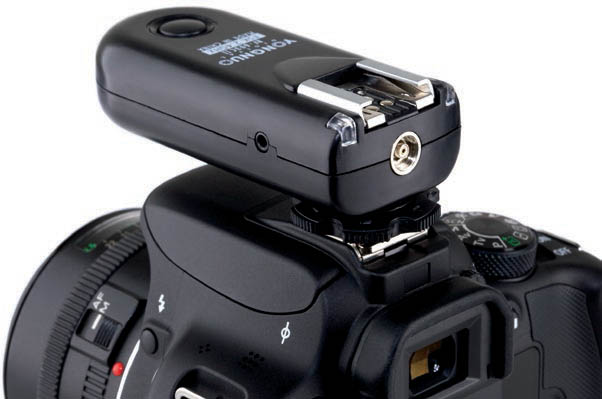
11.10.9 Yongnuo RF-603C II
The memorably named RF-603C II is a 2.4 GHz transceiver, so it can operate as either receiver or transmitter. Either way it’s a small rounded black box that fastens to a flash unit’s foot or a camera’s hotshoe. The C in the product name means it’s designed for Canon gear.
The units are powered by two AAA cells, and have three position power switches: off, transmit, and transmit or receive. Battery life in receive mode is 10× less than transmit-only. It has small DIP switches in the battery bay allowing for up to 16 different channels to be used, and the device can also trigger cameras remotely as well as flash units through the use of the right cable.
11.58

11.59

11.60 The cockpit of the Raygun Gothic Rocketship (figure 6.12). This photo is lit by a mixture of daylight coming through the portholes, tungsten lamps on the simulated displays, the glowing video monitor, and a blue-gelled 580EX Speedlite controlled by a RadioPopper wireless remote on the next floor down.
11.11 Off-Camera Method 3—Radio with automatic metering
The most technically complex off-camera flash technology is radio with automatic output control. For years this was only possible through third-party gear, but in 2012 Canon joined the party with the introduction of radio wireless E-TTL. Unfortunately, none of the systems here are interoperable, which means none of them can be used together.
11.11.1 Canon radio wireless E-TTL
It was a long time coming, but Canon’s radio-frequency wireless system was worth the wait. In 2012, Canon released the Speedlite 600EX-RT, the company’s flagship hotshoe-mounted flash unit that can transmit and receive radio commands using the 2.4 GHz band. Full E-TTL trigger and metering commands can be sent over the air from a master unit to as many as 15 remote flash units. Unlike optical wireless E-TTL, radio E-TTL is solid and reliable since it doesn’t rely on line of sight. The system expanded in usability in 2015 with the release of the midrange 430EX III-RT.
The latter device is particularly notable. For many years Canon only sold high-end units that could work as a master, with more affordable midrange units being slave-only. This made sense from the point of view of product marketing, but not from the point of view of a photographer. You don’t need a high-powered flash unit as master— you’re better off having powerful slave units. Fortunately, amid much cheering from Canon users, this all changed when the 430EX III-RT brought radio master capabilities (though not optical master, oddly) to the midrange lineup.
“RT” in a Speedlite name refers to radio technology. For licensing reasons, Canon doesn’t sell RT devices in certain countries. There are thus two nearly identical versions of the 600EX and 430EX III—one with radio capabilities and one without.

11.61 Aside from the names, the Speedlite 600EX-RT (left) and 600EX (right) look almost identical. The absence of a working LINK light is a giveaway, though.
11.11.2 Radio commands
Canon’s radio wireless E-TTL is conceptually similar to its optical system with an on-camera master controlling off-camera slaves, but instead of using coded pulses of visible light or infrared, radio signals are transmitted. The maximum range is about 30 meters or 100 feet, depending on local interference.
While this is a great system, it’s not free of drawbacks. Some of the main gotchas include:
- The cost of the new gear. The RT devices aren’t cheap. Fortunately, the 430EX III-RT is the first midrange wireless master, which helps. There are also third-party products on the market designed to be fully compatible with Canon’s radio system, which are all much cheaper.
- You can have up to 15 separate Speedlite units in any radio wireless setup—one master and up to 14 slave units, regardless of flash group. This should be enough for most users, though the previous optical system has no such limits: any slave flash that can see the command from the master can respond.
- No EOS camera has an integrated radio transmitter at this time.
- Post-2012 “radio-aware” cameras (see next section) are the only ones that can use up to 5 separate flash groups configured any way you want. Older cameras that are not radio aware are stuck with the traditional 3 groups in the A:B C model.
- High speed sync. HSS in radio wireless mode is only available with post-2012 “radio-aware” models. This doesn’t affect the same flash unit physically connected to the camera via the hotshoe, or when using optical wireless flash.
- Older cameras that are not “radio-aware” can’t use high shutter speeds in radio wireless mode. Specifically, the maximum X-sync speed drops by about one stop.
11.11.3 Radio-awareness
Along with radio flash technology, in 2012 Canon also released the first EOS cameras designed to speak radio. The manuals refer to these as “EOS digital cameras released since 2012,” which is awkward and inaccurate since one post-2012 model (the Rebel T5/EOS 1200D) has only partial radio support (radio settings must be set on the flash unit, not the camera).
To clear things up I refer to the following three basic categories:
- “Radio-incompatible” cameras: These are cameras that can’t use radio wireless E-TTL at all. This includes nearly all film EOS cameras and the EOS 1D and 1Ds. E-TTL film bodies can only use Canon’s radio wireless in manual flash or stroboscopic flash modes.
- “Radio-compatible” cameras: These are digital EOS bodies released earlier than 2012. Since they predate radio E-TTL, they think radio-enabled Speedlites are optical ones. They can use radio wireless E-TTL, but have four specific limitations. First, they can’t use radio groups. Second, they can’t use high-speed sync (HSS) over radio. Third, their maximum X-sync is decreased by a stop when using wireless. And finally, even if they have menu functions for Speedlites (ESC) they can’t enable radio-specific features.
- “Radio-aware” cameras: These are EOS bodies specifically designed to support the full range of radio wireless E-TTL features. They support groups, HSS, modeling flash in radio mode, should have normal maximum X-sync, and have menu systems (ESC) that can control radio-specific features. EOS cameras introduced since 2012, except for the Rebel T5/EOS 1200D, are radio-aware. Note that radio E-TTL does not work if the camera is set to an icon mode—it has to be in P, Av, Tv, M, or bulb modes.
The categories listed above aren’t official Canon names (though I think they should be!), but I use them here to help avoid confusion.
At time of writing in mid 2015, radio-compatible 2007–2011 cameras with menu control over Speedlites (ESC) are the EOS 1Ds Mark III, 1D Mark III, 1D Mark IV, 5D Mark II, 7D, 60D, 50D, 40D, Rebel T3i/600D, Rebel T2i/550D, Rebel T1i/500D, Rebel XSi/450D, Rebel T3/1100D, Rebel XS/1000D, Rebel T5/EOS 1200D.
Radio-aware cameras are the EOS 1D X, 5D Mark III, and the EOS M-series (M, M2, M3).

11.62
11.11.4 Radio wireless groups
Canon radio wireless E-TTL can operate much like optical wireless, with two groups (A and B) controlled by ratios and a third (C) controlled by exposure compensation. But for more flexibility, radio-aware cameras have another option available to them: five completely separate groups, with independent metering systems (E-TTL II autoflash, manual, or external autoflash) for each one. You can then set exposure compensation (E-TTL II) or flash output (manual) for each group.

11.63
This feature eliminates one of the long-standing weaknesses of Canon’s wireless system: the awkward A:B C ratio system. Unfortunately, at time of writing only radio-aware cameras can use this feature.
11.11.5 Channels, IDs, and flash clash
One problem with radio flash technology is that one photographer could accidentally trigger the flash units of another photographer nearby. In the case of optical wireless this is perhaps less of an issue, since you can probably see when someone else is inadvertently firing your flash units. But in the case of radio, which can pass through thin walls and travel great distances, the risk is much higher and troubleshooting is more difficult. Even worse are situations where many photographers are working a small area, such as a movie premiere or press conference.
Canon’s solution for this problem is a “Radio ID” feature, which allows you to assign a four-digit ID number to each of your flash units. With up to 10,000 different ID numbers available, the chances of flash clash are lowered dramatically. There are also 16 radio channels available, and RT units can scan for other devices to determine which channel has the least interference. ![]() 11.64
11.64

11.64
11.11.6 Quantum Q-TTL
Quantum’s Q-TTL system is the oldest radio-frequency wireless flash triggering system on the market today that supports automatic power output levels on Canon cameras. It consists of a number of different products that interoperate in various ways, all based around the FreeXwire transmitter.
11.65
Quantum has decoded the flash-related commands sent by Canon cameras and produces a hotshoe attachment, the Quantum TTL Adapter, which can interpret those signals. The attachment connects to the FreeXwire transmitter and sends flash sync and metering information by radio to FreeXwire receivers. These receivers can attach directly to the side of Quantum Qflash units. The radios use eight different frequencies and transmit up to 1,000 feet. Each flash unit can be in one of four zones, which can be turned on and off directly from the transmitter.
Quantum flash units are somewhat similar to Canon Speedlites in that they’re battery-powered portable flash units, but they differ in that they have very high light output levels and require external battery packs. Instead of swiveling or zooming flash heads, they have bare flash tubes, protected by clear glass shields, to which various light-altering devices can be attached. They support simple metal reflectors, small softboxes, and other accessories. In short, they are high-output portable devices meant for professionals, such as wedding photographers. ![]() 11.65
11.65
11.11.7 RadioPopper PX
The RadioPopper PX, successor to the P1, takes an interesting approach to handling wireless signals. Instead of interpreting commands directly from the camera, the RadioPopper intercepts signals sent by a master Canon flash unit operating in optical mode. It reads those instructions, converts them to radio signals, and transmits them to a receiver. The receiver then sends the instructions back to the slave unit using infrared. Essentially the RadioPopper PX is a radio bridge or translation system, and thus it automatically supports all optical wireless E-TTL functions. ![]() 11.66
11.66

11.66
RadioPopper PX comes in matched transmitter/receiver pairs. The transmitter has a small pickup, like a tiny version of the coils used in electric guitars, which detects the magnetic burst produced by a flash unit when it fires. Its small fixed antenna sends commands using one of 16 separate radio frequencies. The transmitter must be fastened to the flash head of a Canon-compatible master device, such as any 500 series EX unit or the ST-E2, using tape or Velcro.
The receiver has no pickup, just a single, directional antenna that can be rotated to receive the signals from the transmitter. Additionally, it has an infrared diode on the back that plays IR signals back to a Speedlite. For all this to work, the receiver must be attached very carefully, since the slave won’t respond if it can’t see the RadioPopper’s IR output. Also, if a slave flash unit receives optical signals from the master flash unit as well as radio-bridged RadioPopper signals from the RadioPopper receiver, things can get confused.
RadioPopper advantages
The strength of the RadioPopper system is that it fully and transparently supports all wireless E-TTL features without modification, since it’s simply bridging the normal optical communications system used by the flash units. All 500EX and 400EX series Speedlites are supported, as is the ST-E2 transmitter. Attach RadioPoppers to a set of flash units and a very convenient automatic system becomes possible. No need to walk over to each slave unit to adjust its output: this can all be controlled from the master flash unit. The PX system has a good working range of about 300–1,500 feet.
Of particular note is that radio-controlled high-speed sync flash is possible, up to the camera’s highest shutter speed. This was a technical innovation introduced with the original RadioPopper P1.
PX devices are small, lightweight, and easy to use. They allow for the convenience of E-TTL without short distance and line of sight restrictions. They can also work with sync-only RadioPopper JrX units. ![]() 11.67
11.67

11.67 A RadioPopper PX receiver attached to a 580EX II slave
RadioPopper limitations
The RadioPopper system’s main advantage—a radio bridge to wireless E-TTL—is also its main weakness. It requires full wireless E-TTL capable master and slave units, making it expensive for hobbyists. It isn’t intended for use with simple manual flash triggering, and can’t extend E-TTL’s capabilities (e.g., second curtain sync is not supported). RadioPoppers can be used in conjunction with Nikon cameras and flash units, but note that all devices have to work on the same system—Canon E-TTL or Nikon iTTL. The RadioPopper can’t translate Canon commands into Nikon commands or vice-versa, and cannot speak Canon radio wireless.
Another key point is that the small, flat RadioPopper boxes must be attached to sending and receiving flash units somehow. This can be done semi-permanently with double-sided tape, Velcro hook and loop fasteners, or an optional RadioPopper mounting bracket. Regardless of how it’s done, the result is a small box that sticks out from the side of the flash unit. This can be a little awkward, particularly on flash units with curved fronts like the 580EX, and it can cause reliability problems if the RadioPopper receiver is bumped out of alignment with the wireless E-TTL receiver window.
The PX devices are fairly minimalist. Both components are small, lightweight, thin-walled plastic boxes. They have a very terse screen and input system, which consists of two seven-segment LED numerals, two LED lights, and two push buttons. Configuring the devices involves cycling through various two-letter menu choices, and it’s essential to have the manual on hand to know how to work it. For this reason, it’s best to configure and test the devices prior to a shoot. It also lacks a test button, which makes setup testing somewhat inconvenient. The RadioPoppers do not have any way for firmware updates to be uploaded. If the unit goes into P1 clone mode, for compatibility with a previous RadioPopper model, it can seem unresponsive.
RadioPoppers built for the North American market transmit from 902–928 MHz. This means they operate on the same frequency band as GSM-900 mobile phones used almost everywhere in the world except for North America and Japan.

11.68
11.11.8 PocketWizard ControlTL devices
The third radio transmitter system that supports power output levels is from LPA Design. Best known for its sync-only PocketWizard devices (section 11.10.1), the company has produced some highly programmable and compact hotshoe adapters that enable a wide range of advanced Canon E-TTL features wirelessly.
Like the Quantum devices, the ControlTL devices don’t bridge E-TTL commands from a master flash unit, but connect directly to the camera and interpret the commands it would normally send to a flash unit. Radio waves are then used to transmit sync, metering, and other data. ![]() 11.68
11.68

11.69
At time of writing the product line consists of two devices: the MiniTT1 and FlexTT5. The MiniTT1 is a very compact transmitter, powered by a CR2450 lithium coin cell, which fastens to the camera’s hotshoe. It has an integral antenna, a few switches and buttons, and a pass-through hotshoe attachment on the top, which connects to a flash unit’s foot. The hotshoe allows for a flash unit and a MiniTT1 to be attached to the camera simultaneously if desired, but it does not let the unit act as a receiver. ![]() 11.69
11.69
The FlexTT5 is a noticeably larger device that can act as either a transmitter or receiver. Since it needs to sit and wait for radio signals when it’s in receive mode, it’s powered by two AA cells. The receiver connects to a camera via a hotshoe, adds a couple of sockets for controlling external flash units or remote cameras, and has a swiveling antenna.
Both devices are available in Canon and Nikon versions, but the two product lines are dedicated to one manufacturer only and do not interoperate or translate one maker’s TTL commands to another’s. The PocketWizard system is not compatible with Canon’s wireless radio technology.
Basic features
Like other radio remotes, the two devices can be set up in simple master / slave fashion. The MiniTT1 attaches to the camera’s hotshoe and transmits sync and metering data wirelessly by radio to the FlexTT5, which then commands any flash unit connected to it to fire. ![]() 11.70
11.70

11.70 MiniTT1 on-camera
Alternatively, one FlexTT5 can be used as a master and another as a slave. The system is compatible with many aspects of Canon’s E-TTL; it supports flash metering, ratios, high-speed sync mode, and flash exposure compensation set on-camera. E-TTL ratios are supported, though they’re referred to as “zones” and not “groups.”
At time of writing, stroboscopic mode, flash bracketing (FEB), menu control of flash units, and some other functions are not supported by ControlTL devices.
Up to 26 different transmission frequencies are available to reduce the chance of channel conflict with another photographer’s PocketWizard devices. The FlexTT5 can also be used to trigger a remote camera as well as a remote flash unit. There is also the AC3 device available, which makes it easy to set the output levels of different channels via rotating wheels.

11.71 PocketWizard AC3 ZoneController, which fits onto the MiniTT1 Transmitter or FlexTT5 Transceiver.
Compatibility with sync-only PocketWizards
The ControlTL devices can transmit on the same frequencies as regular sync-only PocketWizard devices. This allows photographers who have an investment in the older system to use the devices as sync-only receivers with a MiniTT1 / FlexTT5 transmitter. Note that all devices must be designed for use in the same region in order to interoperate, for the regulatory reasons mentioned earlier.
Manual output controlled by the 580EX II
When a 580EX II is connected to a ControlTL device’s hotshoe, it’s possible to control the manual output of three separate groups (“zones”) of flash units. Power output is specified in fractions, not ratios as is normal for E-TTL.
Upgradeable via USB port
Devices such as the ControlTL are little computers driven by software. Many such hardware devices are difficult or impossible to reprogram, but the MiniTT1 and FlexTT5 have mini USB type B ports for connecting to a personal computer. When LPA Design releases new firmware, it’s easy for users to download updates from the Internet. The company has introduced a number of firmware updates that fix problems and add new features this way.

11.72 PocketWizard menu
Advanced features
Because they talk directly to the camera and flash unit, the ControlTL devices offer some interesting and unusual features. Most notable, perhaps, is the fact that the maker has released software upgrades that add a variety of new functions, such as more efficient high-speed and second curtain sync and more powerful preflashes (in addition to fixing other problems).
Higher efficiency sync
Normally, Canon high-speed sync flash starts pulsing the flash tube a bit before the shutter actually opens. The ControlTL devices, since they control the flash unit directly, have tightened up this flash trigger timing so that the tube begins pulsing closer to the shutter opening and closing times. This can mean increased high-speed sync output on some camera models, which translates to greater light output and decreased battery usage.
A similar trick is employed in the ControlTL version of second curtain sync. Flash timing is moved closer to the actual second curtain closing, resulting in less blurring at the front edge of a moving object.
HyperSync
Perhaps the most interesting feature is a function called “HyperSync,” which gives the ControlTL boxes the ability to exceed the camera’s X-sync speed without using high-speed sync at all.
As noted in section 7.11, flash units can’t expose the full frame of a focal plane camera if the shutter speed goes too high. The usual solution to the problem is to pulse a flash tube very rapidly, enabling high-speed sync. ControlTL devices support regular high-speed sync but add another way to exceed a camera’s X-sync.
HyperSync takes advantage of the fact that the light produced by a flash tube drops off gradually if the tube is fired at full power. If fired at partial power, most battery-operated devices cut off power to the tube sharply, and the light drops pretty well immediately. But at full power, the light output has a long “tail” as it decreases. HyperSync fires the flash tube before the sync command is sent, and thus before the shutter actually opens. Then, as the light output gradually drops off, a full frame can be exposed at a high shutter speed.
HyperSync requires very precise timing over flash firing relative to the shutter opening, and each camera mechanism has slightly different time requirements. For that reason, the Windows or Mac OS X software included with the ControlTL hardware allows the timing to be adjusted in minute increments. Through trial and error, it’s possible to squeeze the most performance out of each flash unit / camera combination, thus getting the highest shutter speed possible while maintaining full flash exposure and avoiding the black bar problem. It’s also possible to specify the shutter speed at which the ControlTL device will transition from HyperSync to regular Canon E-TTL high-speed sync. ![]() 11.73
11.73

11.73
The biggest weakness of the ControlTL system springs from one of its advantages. For compatibility, the devices transmit on the same frequency range as their predecessors, so they can trigger a Plus II or MultiMAX remote. Unfortunately, it so happens that certain Canon Speedlites emit radio-frequency noise in the same band when they fire. This noise is well within legal limits, but it interferes with the PocketWizard radio transmission. For this reason, ControlTL performance with certain Canon Speedlites is severely curtailed. Range may drop to 30–800 feet, compared to the 1,500-foot expected distance range from regular PocketWizard products.
The problem is severe with ControlTL units sold in North America, which operate on a frequency band from 340 to 354 MHz. Units sold in Europe operate at 433–434 MHz for regulatory reasons, and therefore have greater range. However, the CE-certified products are not available for sale in the U.S. and Canada.
The problem does not occur with non-ControlTL PocketWizard devices because they are usually situated a short distance from the flash unit when operating as receivers. ControlTL units, however, generally clip directly to the flash unit’s hotshoe.
Various approaches to mitigating the effect of this interference are available, including using off-camera shoe cords to connect the receivers to the flash units (rather than connecting the receivers directly to the flash feet), adding noise-shielding ferrite clamps to these cables, or adjusting antenna orientation. But these measures obviously represent something of an inconvenience. The official PocketWizard solution is to provide a “sock” of noise-blocking metallic fabric, the RF Soft Shield, which can be wrapped around an offending Speedlite.
The Speedlites that produce the most noise, and thus have the shortest range, are the 430EX, 580EX, and 580EX II. The Speedlites 550EX, 420EX, and 430EX II produce the least amount of noise.
Not compatible with entire Canon range
ControlTL devices are not compatible with all Canon cameras and flash units. Specifically, they’re compatible with most Canon digital SLRs since the 20D, and most Speedlite EX models and the ST-E2. Earlier cameras, including all film models, and TTL-only flash units are not supported.

11.74 Avoiding the hassle of wires, radio remotes are ideal for triggering flash units placed in unusual locations, such as this phone booth near the Royal Albert Hall in London. A high-powered Quantum Qflash unit was used, triggered by a FreeXWire radio remote. EOS 5D, 2.5 sec at f/8. ISO 100, 24mm.
11.11.9 Phottix Odin
The last system is the Phottix Odin. This is a 2.4 GHz radio system that offers full TTL support to remote flash units. It handles three separate groups, and you can apply flash exposure compensation to each one individually.
The product consists of an LCD-equipped transmitter that fits in the camera’s hotshoe, and a small receiver for each slave unit. The transmitter lets you specify output channels at the press of a button. High speed sync through to 1/8000 sec is supported, and you can use manual flash output if you prefer. The product has a 300 foot/100 meter advertised range.
The Odin is very affordable, but is not compatible with Canon radio wireless. The Phottix Indra battery-powered flash unit (see 13.1.5) is compatible with the Odin. ![]() 11.75
11.75

11.75