
10 Manual Flash Metering
London Eye. Snowfall over the London Eye Ferris wheel, London Southbank, England. A 580EX II flash unit was handheld over the camera and triggered manually at half power in order to illuminate and freeze the falling snow. Without flash the fast-moving and dimly lit snowflakes would not have recorded in the final picture. EOS 5D, 0.8 sec at f/5.6, ISO 100, 22mm.
This is an example of totally manual open flash to highlight foreground objects.
The automatic flash metering technologies described in the previous chapters are quick and easy to use. They’re ideal for casual snapshots or for rapidly changing situations such as those encountered by photojournalists. But, while computers are great at performing rapid calculations controlled by complex programs, they’re pretty lousy at making artistic judgment calls. Automatic flash metering systems are designed to create flat, even results, which aren’t necessarily what you want.

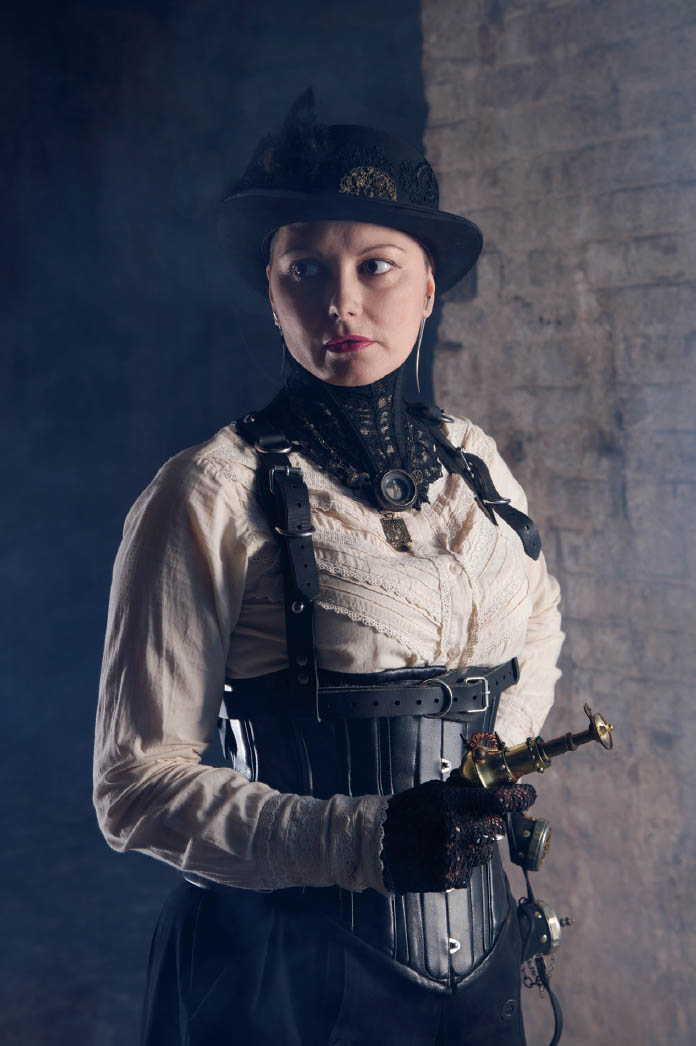
10.1 This photo was taken in a simple studio setting. Exposure on the camera was in manual mode, set to 1/50 second at f/5.6. A single Bowens Gemini mono-light in a medium-sized softbox, positioned camera left, was used. For more details on these items consult chapter 13: Studio Flash.
Automatic systems are designed to measure light that is reflected off flash-illuminated objects. If light from a flash unit is directly visible—perhaps because a unit is pointing towards the camera or light is reflecting off a shiny surface—then automatic metering will be thrown off and the scene will probably be quite underexposed. This is a real problem with on-camera flash when there’s a mirror in the frame. Auto flash can also struggle when multiple flash units are fired together.
For these reasons, ultimate control over lighting is achieved by using manual flash. “Manual” is quite literally that: the output level of each flash unit is set directly by you using buttons or dials, without a single automated metering system in sight. The metering for the scene is done using a handheld flash meter or just empirical testing. The flash units are carefully positioned to light the scene, usually augmented with various light modifying devices such as reflectors, umbrellas, or softboxes.
In a sense, manual flash involves stepping back in time to the era when sync (timing of the flash with the shutter opening) was the only real control that the camera had over the flash unit. With automatic flash, the brightness of the flash unit is determined by the camera. With manual flash, it’s all up to you.
Manual flash sounds daunting, but many developments over the past few years have contributed to the technique’s resurgence in popularity.
10.1Manual flash metering
As mentioned earlier, manual flash metering is tricky to master because the effects of a brief pulse of light can’t be visualized by the naked eye. The ambient light meters built into all EOS cameras can’t be used for manual flash metering since they’re not designed to do so.
There are essentially two ways of determining correct flash exposure without using automated flash: trial and error, and flash meters.
10.2Trial and error
This is simply the process of taking a photo, examining the results, then adjusting the flash output by hand. Repeat until good results are obtained.
In the days of film this was pretty impractical, since regular film cost a lot of money and took time to develop and print. Professionals working in a studio would often shoot Polaroid instant photos (frequently using interchangeable Polaroid backs on their cameras) to test out lighting situations, but this was more for testing lighting quality, not for metering.
In today’s digital world, trial and error is actually a straightforward and workable option, even though it initially sounds a little crude as a technique.
10.2.1Manual flash in a digital age
The arrival of digital has changed everything. Digital cameras boast preview screens, histograms, and EXIF shooting data, all of which simplify manual flash dramatically. Now you can tell within a second whether a given manual flash setup has worked or not. If it hasn’t, it’s easy to fix and reshoot. The feedback loop has been tightened, transforming the technique.
10.2 A photo taken using two Bowens Gemini R studio flash units, powered by a Travelpak battery. No flash metering was used; output levels were set by hand based on experience and judicious examination of the camera’s preview screen.
Reviewing a camera’s LCD after a shot (jokingly known as “chimping”) is easy to deride. But it has opened the doors to countless photographers who wouldn’t have learned manual flash techniques so easily before. Indeed, this sort of light metering technique may offend photographers trained in traditional methods, since it can be a bit of an intuitive hit or miss. On the other hand, it’s also straightforward and effective, even if the photographer may not completely understand the specifics of how flash works. With time, an experienced photographer will learn the most likely flash levels required to illuminate a given scene, and will only need a test shot or two to hone the settings. ![]() 10.3
10.3

10.3
The Internet has also been a driving force in the changing destiny of manual flash metering. In early 2006, photojournalist David Hobby started a modest photographic blog, Strobist.com, which he used as a teaching tool for getting beginners to take their flash units off their cameras. Within a couple of years, the site had become the hugely popular central hub for learning about and evangelizing off-camera flash photography, typically using affordable battery-powered flash units. Now “strobism” is often used to refer to the field in general.
10.2.2Digital histograms
Histograms are an invaluable tool for determining correct exposure for either ambient or flash-lit photographs. All digital EOS cameras can display these small charts next to an image on the camera’s preview screen. The chart can indicate brightness (black and white) or RGB (color) information, and can show the frequency of occurrence for each pixel level in the image.
Camera histograms are simple bar charts with each bar showing the frequency of a given range of brightnesses—dark to the left and bright to the right. A histogram skewed to the left is a dark image, and a histogram skewed to the right is a bright image. Analysis of a histogram is a sophisticated way to determine how well an image has been exposed. An image with a lot of bars on the left side might require more illumination, for example. Or an image with a number of bars lined up on the right side might be heavily overexposed and blown out.

10.4 A very dark image. The histogram clearly shows that the bulk of the pixels making up the photo are over to the left, or dark, end.

10.5 A lighter image. The histogram indicates that a fair number of pixels are essentially pure white, with some midtones (skin color) and dark areas (hair).
10.3Flash meters
A flash meter is the traditional tool used to measure flash output with control and precision: a handheld device that can measure the brief pulse of light from a flash unit. They’re not cheap, but they’re an essential tool for studio professionals who need accurate, predictable, and repeatable results. Flash meters may be overkill for the average hobbyist, but it’s useful to know how they work.
A typical flash meter is shown in use in figure 10.6. The meter is held close to the model’s face while a test flash is fired. The white dome on the top of the unit picks up the light from the flash, and ignores ambient light levels. This is known as incident flash metering and is different from the reflective metering used by EOS cameras and other SLRs.
Reflective meters, like those in a camera’s viewfinder assembly, measure light bouncing back from a subject. Since reflected light has to travel back to the camera from the subject, distance comes into play (see the inverse square law, section 7.14). A highly reflective object far away may meter the same as a darker object closer up. Also, since reflective meters are designed to average everything out to a midtone gray, they can have problems metering very light or very dark subjects.

10.6
Modern, sophisticated multiple-zone evaluative light meters are designed to avoid some of these problems but can’t eliminate them entirely, since even the most advanced computer program can’t know a photographer’s creative or artistic intentions. A moodily lit portrait of a person in a dark room, for example, might be overexposed by an automated camera, which tries to bring up the exposure of the dark areas at the cost of correct exposure of the face.
10.3.1Incident light metering
Incident light meters record the actual light falling on the subject. This ensures that they correctly measure the amount of light required to illuminate the subject and aren’t fooled by distance or the reflectivity of the subject. The drawback is that they have to be positioned close to the subject to record the light levels accurately, as shown in figure 10.6. This is fine in a studio situation, but it could be unworkable for a photograph of a vast landscape.
One of the key advantages of incident meters is that they can be used to measure the amount of light falling on different parts of a scene. Take, for instance, the example of a person in front of a white background. The background should be pure white, but if it were to be excessively lit, then light would spill over onto other areas. By using a light meter, it’s possible to measure (in f-stops) the difference in illumination between the background and subject. Then—assuming the background and subject are lit by different lamps or flash units—the output of those devices can be adjusted precisely. Studio photographers and cinematographers (though the latter measure continuous light levels and not flash) often walk the set to check light levels before shooting, using this technique.
Of course, many meters are multipurpose in nature. The Sekonic flash meter shown in figure 10.7 can also measure ambient lighting, either incident or reflective spot, as well as flash. It can even display flash levels as a percentage value compared to the ambient light levels. Ambient metering is essential for metering exposures with older film cameras that lack internal light meters, such as many view cameras. Finally, this Sekonic model has a built-in PocketWizard transmitter (section 11.10.1), which means that it’s easy to fire compatible radio-equipped flash units right next to the subject.

10.7
10.4Choosing a manual flash unit
Quite simply, any flash unit with manual output controls will work. Some units have sliders, some have knobs, and some have buttons. A manual flash can be anything that permits the amount of light produced by the device to be adjusted at will. It can be an old battery-powered hotshoe flash unit from the 1970s, a brand new manual-capable unit designed for a different camera system, or an AC powered studio unit (section 13.1). All that’s needed is manual output control and some way to connect a sync cable or other trigger so that the unit fires when the camera takes a photo.

10.8 This studio unit, a Bowens Gemini monolight, has two dials on the side that are used to set the light output.
Wholly automatic flash units generally aren’t useful for this technique. Many can only fire at full power when triggered by hand, which affords little control over manual flash.

10.9 This shot was lit by two flash units, both controlled by sync-only optical triggers. One was a Speedlite 580EX II, located camera left. The other was the Bowens Gemini monolight shown above, located on the floor behind the mannequins.
Manual flash begins with connecting a flash unit to the camera or to a triggering device. In the case of a hotshoe flash unit, this can be done by sliding the device into the camera’s hotshoe. In the case of off-camera flash or studio equipment, it can involve attaching an electric cord, a light sensor, or a wireless controller. But before anything is physically connected to the camera, the matter of trigger voltages must be addressed.
10.5Trigger voltages
Electronic flash units work by pumping high voltage electricity through their flash tubes. These powerful electrical discharges are fired by a triggering voltage, and many older flash units connect the trigger circuitry directly to their controlling switches. That means when a camera’s flash contacts close, there may easily be anywhere from 50 to 200 volts flowing through them. This isn’t a problem restricted to AC powered studio flash, since even battery-powered flash units have high-voltage internal circuits. Battery units use special step-up circuitry to transform the low voltage from the batteries into the high voltage needed to power the flash tube.
Old mechanical cameras could handle such high voltages with aplomb, but many EOS cameras employ delicate flash sync contacts. Some EOS shutter switches are only rated to six volts and can be destroyed by high voltages. The damage isn’t usually instantaneous but cumulative with repeated use, as arcing and pitting slowly destroy internal components. So it’s vitally important to check both the trigger voltage of a flash unit and the maximum trigger voltage of a camera before plugging in any non-Canon flash unit in.

10.10 This old Vivitar flash unit built in the 1980s has a trigger voltage of just over 8 volts. Whether this is safe or not on a camera rated for 6 volts is something of a judgment call. It’s probably fine, as a 2-volt difference isn’t that significant, but anything much higher should probably not be connected directly.
10.5.1Measuring the trigger voltage
Measuring a flash foot is quite simple. First, fully charge up the unit by turning it on and waiting for its flash ready light to glow. Then take a voltage-measuring device, such as a simple multimeter or multitester, and set it to measure DC volts. Touch the black (negative) probe of the multimeter to the side connector of the flash unit’s foot and the red probe to the foot’s center contact. The meter will display the trigger voltage. ![]() 10.10
10.10
If the trigger voltage exceeds the camera’s limits, then a voltage-limiting device can be used. These accessories sit between the camera and the high-voltage flash, keeping things at a safe level. ![]() 10.11
10.11
Trigger voltage mismatches aren’t a universal problem, particularly with most 1-series cameras and recent digital EOS bodies. Instead of fragile electric switches, these cameras use semiconductor switches that can withstand up to 250 volts. Consult appendix C for a table of models that have this capability. Conversely, most flash units on the market today are designed with low trigger voltage circuits because of this issue; it’s mainly older models that can be a problem.
But to be honest, it’s simpler just to use an optical or radio trigger, which bypasses the whole trigger voltage problem altogether and eliminates the hassle of using a cable. See chapter 11 on off-camera flash.

10.11 A Wein SafeSync. While somewhat crude-looking, this device can save a camera’s shutter from flash-derived destruction. It fits into a camera’s hot-shoe and also allows PC cables (section 11.4) to be plugged into cameras that lack PC sockets.
10.6Incompatible shoes
Generally speaking, hotshoe connectors designed for other camera systems are completely incompatible with EOS cameras. This is because they use different pin configurations. ![]() 10.12
10.12
Some devices have all-metal cold shoes for accessories, or hotshoes with incompatible pin configurations. These could be a problem if they inadvertently short out any of the four small data contacts on EOS cameras or flash units.
Of particular concern are cheap flash units with large, crude central hot-shoe contacts. If such a contact were to touch one of the four EOS data contacts, damage could occur if the device has a high trigger voltage.

10.12 This Nikon shoe is not compatible with EOS cameras.
10.7Autoflash metering
It’s worth mentioning the earliest form of automatic flash metering: “autoflash,” exemplified by the venerable Vivitar 283/285 hotshoe battery units introduced in the early 1970s. These flash units are self-metering, and the only control the camera has over the flash unit is a sync signal.
Autoflash units contain small light sensors on the front that monitor the amount of light reflecting back from the subject when the flash fires. It’s kind of like filling a car’s empty fuel tank and stopping when the numbers on the pump hit a predetermined point.
Once a reasonable exposure is determined by these sensors, an electronic component known as a thyristor is used to shut off power from the flash tube, immediately “quenching” the light. There is a relationship between the duration of the flash pulse and the distance from the subject, with longer pulses generally needed to illuminate subjects farther away. Autoflashes are sometimes referred to generically as “thyristor” flash units, though this is inaccurate since many flash units are thyristor-based but are not autoflashes.

10.13 A classic Vivitar 285
Autoflash works surprisingly well despite its simplicity. In fact, many experienced wedding photographers and photojournalists still rely on auto-flash units in today’s digital age, since the units can give fairly predictable results with experience. However, an autoflash is easily fooled by dark areas or highly reflective surfaces, can’t distinguish between light reflecting back from objects outside the frame of the photo, and can’t be used as a fill flash very easily. It’s also generally designed to meter for the typical area covered by a normal lens, so it will meter inaccurately if used with a long telephoto or a very wide lens.
Autoflash requires more knowledge on the part of the photographer and really only works in single-light setups. Most autoflash units require the ISO / film speed to be set along with the lens aperture. Based on these two pieces of data, an autoflash will attempt to meter correctly using the built-in sensor on the front of the unit. ![]() 10.14
10.14

10.14
Autoflash has never been a key part of the EOS technology lineup, though the discontinued Speedlites 480EG and 200M used it. A modern variant lives on in the 580EX II and 600EX/600EX-RT. Canon refers to the technology these days as “flash external metering”; abbreviated as Ext.A and Ext.M. Ext.A works only with post-2007 digital cameras, as it automatically detects the camera’s ISO and aperture settings and uses that for the autoflash calculations. Ext.M requires you to plug the ISO and aperture settings into the flash unit yourself.
Some third-party manufacturers, notably Metz, manufacture autoflash units that can be used with EOS cameras.