![Custom Menu E1–3. Exp/ISO/BULB/[Meter]](https://imgdetail.ebookreading.net/cover/cover/EB9781681986654.jpg)
Custom Menu E1–E3. Exp/ISO/BULB/[Meter]
The E. Exp/ISO/BULB/[Meter] menu is primarily composed of functions that directly affect how the image is exposed. There are a total of 19 different functions organized into three menus. We will start examining the functions by taking a look at the opening menus for the E. Exp/ISO/BULB/[Meter] functions in figure 7.107.
To enter the menus, you must select E1. (or E2. or E3.) Exp/ISO/BULB/[Meter] from the Custom Menu and scroll to the right. Let’s look at each function in detail.
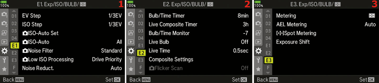
Figure 7.107: The E1–E3. Exp/ISO/BULB/[Meter] menu
EV Step (E1)
Use this function to choose an exposure value (EV) increment when you select a shutter speed, aperture, exposure compensation, or bracketing exposure value. As photographers, we think of exposure in stops. A 1-stop increment doubles or halves the amount of light the camera can use for making a picture, depending on whether you are letting in more light (double) or less light (half). A single stop is equivalent to 1 EV step.
The camera allows you to use finer increments than 1 EV step when you make exposure adjustments. You can select from 1/3 EV step, 1/2 EV step, or 1 EV step. The following three EV step lists show a partial breakdown of EV steps that are available as you adjust an exposure:
1/3 EV step
- Shutter: 1/100, 1/125, 1/160, 1/200, 1/250, 1/320, etc.
- Aperture: f/5.6, f/6.3, f/7.1, f/8.0, f/9.0, f/10, etc.
- Compensation/bracketing: 0.0, 0.3, 0.7, 1.0, 1.3, 1.7, 2.0, 2.3, 2.7, 3.0, etc.
1/2 EV step
- Shutter: 1/90, 1/125, 1/180, 1/250, 1/350, 1/500, etc.
- Aperture: f/5.6, f/6.7, f/8.0, f/9.5, f/11, f/13, etc.
- Compensation/bracketing: 0.0, 0.5, 1.0, 1.5, 2.0, 2.5, 3.0, etc.
1 EV step (1 stop)
- Shutter: 1/60, 1/125, 1/250, 1/500, 1/1000, 1/2000, etc.
- Aperture: f/2.8, f/4.0, f/5.6, f/8.0, f/11, f/16, f/22, etc.
- Compensation/bracketing: 0.0, 1.0, 2.0, 3.0, 4.0, 5.0 (note that 5.0 is the maximum)
The fineness of your exposure control will vary depending on how you set this function; that is, which EV step increment you choose (1/3EV, 1/2EV, or 1EV step). Let’s examine how to select one of the three EV increment values.

Figure 7.108: Choosing an EV step value for exposure control
Use the following steps to select an EV increment value for camera exposure settings:
- Select EV Step from the E1. Exp/ISO/BULB/[Meter] menu and scroll to the right (figure 7.108, image 1).
- Select 1/3EV, 1/2EV, or 1 EV from the menu that appears (figure 7.108, image 2). Refer to the three previous EV step lists to help you decide which EV step is most appropriate for the type of pictures you are creating.
- Press the OK button to Set the value.
Settings Recommendation: I leave my camera set to 1/3 EV step (1/3EV). Most photographers do the same. While using camera-supplied tools, such as the Live Histogram, it is best to have fine control over the exposure value. With 1/3 EV step you can adjust the exposure in fine increments. If you do not need such fine control, experiment with the other two selections.
ISO Step (E1)
All camera menus that allow you to change the ISO use the ISO Step function as the basis for the ISO increments on the camera displays. You can choose from either 1/3 EV step or 1 EV step.
Here is a partial list of ISO increments for both ISO Step values:
1/3 EV step: Auto, L(64) L (100), 200, 250, 320, 400, 500, 640, 800, etc.
1 EV step: Auto, L(64), L (100), 200, 400, 800, 1600, 3200, 6400, etc.
If you want to use smaller increments, leave this setting at the factory default of 1/3 EV. If you want to select ISO values in 1 EV step (1 stop) increments, you can change it here. Let’s see how.
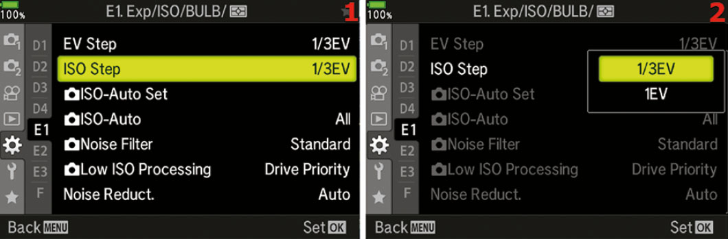
Figure 7.109: Choosing an ISO Step increment
Use the following steps to choose an ISO sensitivity setting:
- Select ISO Step from the E1. Exp/ISO/BULB/[Meter] menu and scroll to the right (figure 7.109, image 1).
- Select 1/3EV or 1EV from the menu that appears (figure 7.109, image 2).
- Press the OK button to Set the value.
Settings Recommendation: I use the 1/3EV ISO Step value because I want fine increments of ISO values to choose from. If you prefer coarser 1-stop ISO sensitivity increments, choose 1EV instead.
[Camera] ISO-Auto Set (E1)
When you set the ISO sensitivity to Auto, the camera will choose the best ISO to use for the current subject, without concern for image noise from high ISO values.
[Camera] ISO-Auto Set is used to control the upper limit of your camera’s ISO sensitivity when using Auto ISO. In effect, you are telling the camera it can use any ISO value, but it cannot exceed that range with higher ISO values. The total available ISO range is from ISO 200 to ISO 6400.
You can also set the lowest shutter speed value that the camera will use when the ISO sensitivity is raised in P and A modes.
There are two submenus in the ISO-Auto Set function:
- Upper Limit/Default: The Upper Limit setting controls the maximum ISO value that you will allow the camera to use in difficult lighting conditions. The camera is free to use any ISO value up to the Upper Limit setting. The Default is the ISO value at which the camera will start.
- Lowest S/S Setting: This is where you can set the lowest shutter speed that the camera will automatically use when you use the P or A modes. If you choose Auto, the camera will automatically set the shutter speed.
Look at the Default and High Limit as a floor and a ceiling. When you use Auto ISO, the camera cannot drop the ISO below the Default floor or raise it above the High Limit ceiling. These values give you excellent control of the Auto ISO boundaries. The Lowest S/S Setting gives you another point of control when using Auto ISO in the P and A exposure modes.
Let’s examine how to choose an ISO value for the High Limit and Default settings, as well as the Lowest S/S Setting.
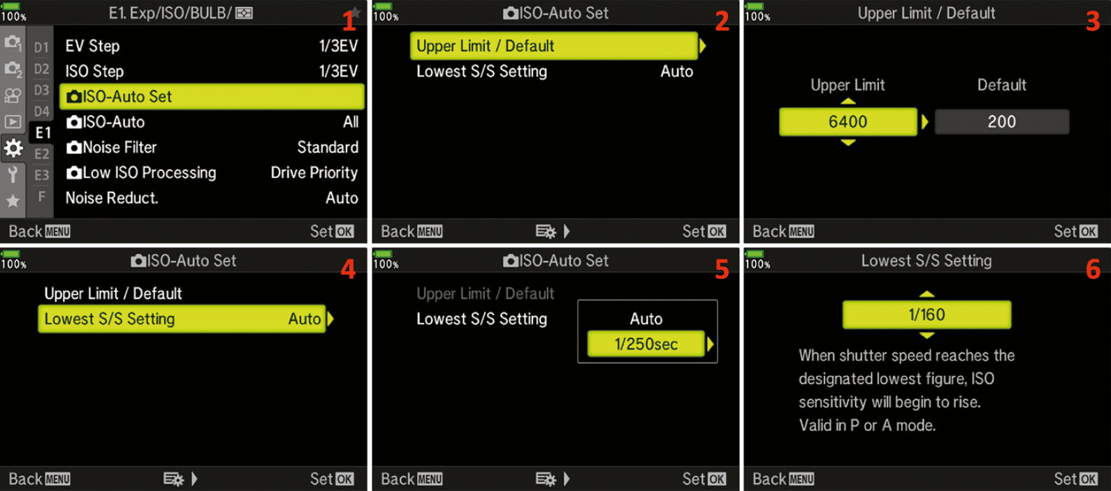
Figure 7.110: Choosing a High Limit and a Default value along with the lowest Shutter Speed for Auto ISO
Use the following steps to choose an ISO-Auto Set value for the High Limit and Default settings along with the lowest Shutter Speed:
- Select ISO-Auto Set from the E1. Exp/ISO/BULB/[Meter] menu and scroll to the right (figure 7.110, image 1).
- Select Upper Limit/Default and scroll to the right (figure 7.110, image 2).
- Choose an ISO value from the Upper Limit up/down menu (figure 7.110, image 3). The available ISO values range from ISO 200 to ISO 6400.
- Use the Arrow Pad to move to the right and choose an ISO value from the Default up/down menu. The available ISO values range from ISO 200 to ISO 6400.
- Press the OK button to Set the two values and return to the previous screen.
- Scroll down to Lowest S/S Setting and scroll to the right (figure 7.110, image 4). Select Auto to allow the camera to automatically set the shutter speed, or choose the lowest shutter speed that you are comfortable with the camera using in P or A exposure mode (from 1/8000 to 30 Seconds) (figure 7.110, images 5 and 6).
- Press the OK button to Set the value.
Settings Recommendation: I use ISO 3200 as my Upper Limit. I don’t like the noise that results with higher ISO values, especially if I don’t nail the exposure. I use ISO 200 as the lower Default value, depending on the ambient light and whether or not I am using flash. When I use flash indoors, I often use ISO 400 as Default and ISO 1600 as High Limit. I use Auto for the Lowest S/S Setting.
[Camera] ISO-Auto (E1)
Use the ISO-Auto function to control which modes on the Mode Dial allow the use of automatic ISO (called Auto on the ISO selection menus; I will use Auto ISO in this book). The factory default is for Auto ISO to be available only in Program (P), Aperture-priority (A), and Shutter-priority (S) modes. Normally Auto ISO is not available when you are using Manual (M) mode, so the selection is grayed out on the menu.
However, this menu allows you to set the camera so that you can use Auto ISO in Manual (M) mode. There are two settings in the ISO-Auto function:
- P/A/S: When this mode is selected the camera allows the Auto ISO function to be accessible on the menus only when you are using Program (P), Aperture-priority (A), and Shutter-priority (S) modes. Auto ISO will be grayed out and unavailable on all ISO selection menus when you are using Manual (M) mode.
- All: When you select this mode the camera will offer Auto ISO on all ISO selection menus when you use P, A, S, or M mode on the Mode Dial. Note that Manual (M) mode is included.
Let’s see how to select a setting.
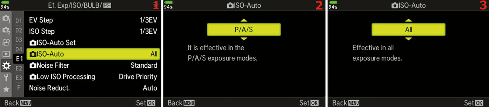
Figure 7.111: Choosing which Mode Dial setting allows Auto ISO
Use the following steps to choose an ISO-Auto setting:
- Select ISO-Auto from the E1. Exp/ISO/BULB/[Meter] menu and scroll to the right (figure 7.111, image 1).
- Select either P/A/S or All from the up/down menu (figure 7.111, images 2 and 3).
- Press the OK button to Set the value.
Settings Recommendation: The All setting makes sense for the types of photography I do (events and nature). I use Auto ISO only when I must get the shot at all costs or when I am shooting just for fun. However, if I wanted to shoot with Auto ISO in Manual (M) mode, I wouldn’t want a limitation imposed upon me.
If you do not think you will use Auto ISO in M mode, simply leave this function set to the factory default of P/A/S.
[Camera] Noise Filter (E1)
The Noise Filter function is designed to remove high-ISO noise from your images by blurring the image slightly. The blurring action tends to blend the grainy noise detail into the darker background, lessening the degrading effect of noise. The camera then resharpens the image to bring out more edge detail.
There are four settings: Off, Low, Standard, and High. The camera defaults to Standard. Each setting blurs the image more, making noise less apparent (and removing image detail), as you move from Low to High.
The camera does an excellent job of noise control for its small sensor.
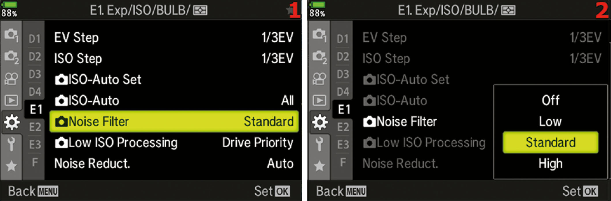
Figure 7.112: Choosing a high-ISO Noise Filter setting
Use the following steps to select a high-ISO Noise Filter setting:
- Select Noise Filter from the E1. Exp/ISO/BULB/[Meter] menu and scroll to the right (figure 7.112, image 1).
- Select Off, Low, Standard, or High from the menu that appears (figure 7.112, image 2).
- Press the OK button to Set the value.
Settings Recommendation: While I was shooting various indoor events (e.g., high school graduations, weddings, baptisms) with my E-M1III, I had to shoot in rather low light. I used ISO 1600 and got excellent results as long as I kept my Live Histogram pegged on the bright side (exposed for the highlights). I found that the Standard high-ISO Noise Filter, which is the default, worked well for me. It seems to balance noise removal blurring and resharpening.
With a smaller sensor, such as the E-M1III Micro Four Thirds sensor, it is critical that exposures are correct in low light. Brightening a high-ISO image will often lead to objectionable noise.
Judicious use of the high-ISO Noise Filter will help protect you from excessive noise in images where the light is not ideal.
[Camera] Low ISO Processing (E1)
You can decide how the camera deals with images shot at low ISO settings by deciding if the camera will use Drive Priority or Detail Priority when shooting. The default for the camera is to use Drive Priority, which means that the camera will take the maximum recordable frames and not slow down the image taking at all. When you pick Detail Priority, the camera can slow down captures to make sure that the detail is captured in each frame.
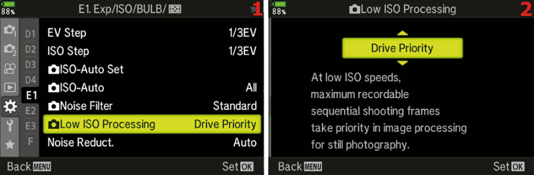
Figure 7.113: Choosing a Low-ISO Processing setting
Use the following steps to select a Low-ISO Processing setting:
- Select Low ISO Processing from the E1. Exp/ISO/BULB/[Meter] menu and scroll to the right (figure 7.113, image 1).
- Select Drive Priority or Detail Priority from the menu that appears (figure 7.113, image 2).
- Press the OK button to Set the value.
Settings Recommendation: I honestly have not noticed any difference in these two settings. If the frame rate and number of photos is more important than the tiny fine details, then stick with the default of Drive Priority, but if you are finding that the images don’t seem as sharp or detailed as they should be, try switching this to Detail Priority. Just keep in mind that it makes little to no difference if you are shooting single frames.
Noise Reduct. (E1)
During a long exposure, the sensor may exhibit more noise than is acceptable. The sensor gets warm after several seconds of use. This warming effect produces amp noise, which causes warmer sections of the sensor to have more noise than cooler sections.
This noise can resemble a foglike brightening around the edges of the frame. Also, there can be bright spots with various colors at numerous places in the image. This special type of long-exposure noise degrades the image in a different way than the noise from high-ISO sensitivity, which appears as grainy ugliness in darker areas of the image.
Using Noise Reduct.
When you enable Noise Reduct. (long-exposure noise reduction) and an exposure is longer than about 2.5 seconds, the camera will take two pictures with approximately the same exposure time. The first picture is normal. The second picture is a black-frame subtraction exposure, which is exposed for about the same duration as the first picture with the shutter closed.
The camera examines the noise in the black-frame subtraction exposure and subtracts it from the first image. Since long-exposure noise (bright spots in random places and fog at the edges) is different from high-ISO noise (grainy degradation in darker areas), the high-ISO Noise Filter function (previous subsection) would not work well with long-exposure noise. Therefore, for those of us who shoot long exposures regularly, the Noise Reduct. function is very important.
The main drawback to long-exposure noise reduction is that the total exposure time is doubled—a 5-second exposure becomes a 10-second exposure—because two exposures are made. The black-frame subtraction exposure is not written to the memory card; therefore, when the noise reduction process is done, you will have only one image with much less noise.
While the black-frame subtraction exposure is being processed, the orange memory card access symbol will blink in the top-left corner of any active displays. While the symbol is flashing, you cannot use the camera. If you turn the camera off during a long-exposure noise reduction session, the image will be lost.
There are three selections available within the Noise Reduct. function:
- Auto: The camera chooses whether or not to use long-exposure noise reduction. It will usually kick in at a shutter speed of about 2.5 seconds or with a small aperture that makes the shutter stay open that long.
- On: Long-exposure noise reduction is active on all pictures taken at all shutter speeds, not just long exposures.
- Off: No long-exposure noise reduction is performed on any image.
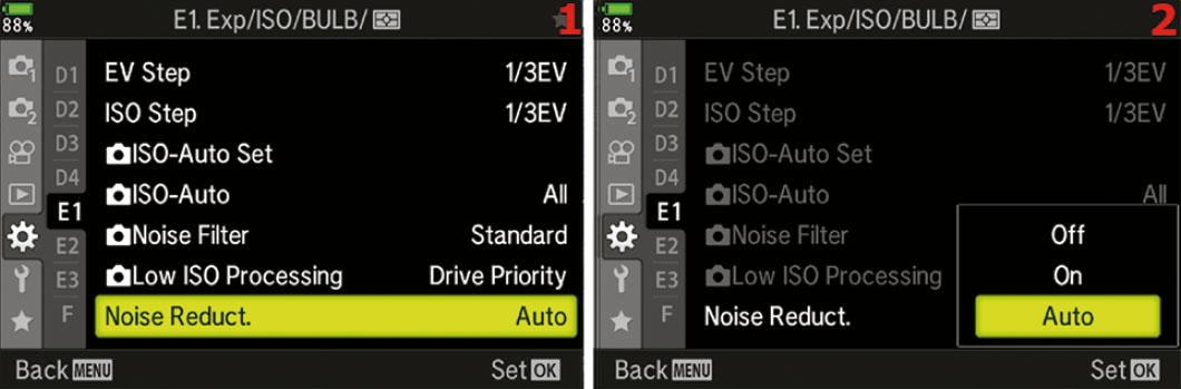
Figure 7.114: Selecting a Noise Reduct. setting for long exposures
Use the following steps to select a long-exposure Noise Reduct. setting:
- Select Noise Reduct. from the E1. Exp/ISO/BULB/[Meter] menu and scroll to the right (figure 7.114, image 1).
- Select Off, On, or Auto from the menu that appears (figure 7.114, image 2).
- Press the OK button to Set the value.
Note: Noise Reduct. may also kick in when ambient temperatures are high, such as on a hot summer day. The sensor can get quite warm when the camera is in the sun absorbing heat.
If you are shooting in any of the Sequential modes, firing off rapid bursts of images, the camera is smart enough to turn off Noise Reduct. for the image bursts. There is no need to slow the bursts down, even on a hot day.
Settings Recommendation: The factory default setting is Auto, and I’ve found that it works well for me. The camera consistently kicks in long-exposure noise reduction at a shutter speed of about 2.5 seconds and results in nicer-looking long exposures than without the setting enabled. When the picture is taken at a shutter speed faster than 2.5 seconds in Auto, the Noise Reduct. function is not used. Auto may be the best choice for most photographers because many exposures are shorter than 2.5 seconds, and Noise Reduct. will be used only when it is needed.
I don’t need Noise Reduct. all the time, so I don’t use the On setting, nor do I want to completely shut it Off. Make some long-exposure shots with and without Noise Reduct. enabled and see which works best for you.
Bulb/Time Timer (E2)
The Bulb/Time Timer function allows you to control the maximum time for the long exposures. You can select from a range of 1min (1 minute) to 30min (30 minutes). When you use the BULB or LIVE BULB shutter speed setting you have to manually hold the shutter open by pressing the Shutter button or using a locking electronic shutter-release cable. When you use the LIVE TIME shutter speed setting, the camera holds the shutter open for you.
Let’s examine how to select one of the Bulb/Time Timer settings.
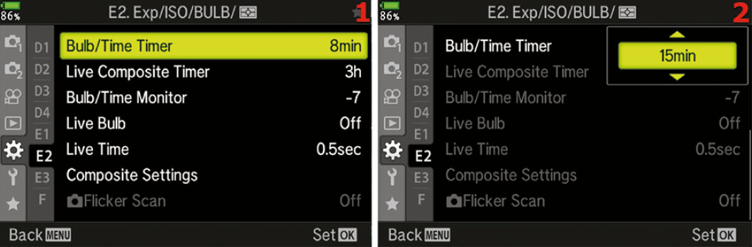
Figure 7.115: Choosing a time-out setting for the BULB/TIME Timer function
Use the following steps to choose a time-out or maximum time to have the shutter open when you use the BULB mode for long exposures:
- Select Bulb/Time Timer from the E2. Exp/ISO/BULB/[Meter] menu and scroll to the right (figure 7.115, image 1).
- Select one of the eight time-out values from the up/down menu. Your choices range from 1min to 30min (figure 7.115, image 2).
- Press the OK button to Set the value.
Note: If you are using the Noise Reduct. function (see the Noise Reduct. subsection), the camera will use long-exposure noise reduction for each of your BULB, LIVE BULB, or LIVE TIME exposures, effectively doubling the time of the exposure. Therefore, a 1-minute exposure will be doubled to 2 minutes, and an 8-minute exposure will be doubled to 16 minutes. This is due to the black-frame subtraction method the camera uses to reduce noise in long exposures. You can disable Noise Reduct. if you do not want the shutter to be open for double the exposure time, but your images may have fog and bright spots because of amp noise and hot pixels.
Settings Recommendation: You will have to decide how long your exposure needs to be for your purposes. For LIVE BULB and LIVE TIME shutter speed exposures, the camera will show you the light buildup of the actual exposure on the Live View display screen so you can see how the long exposure is progressing over time. The screen can update itself—showing you the progress of the exposure—up to 24 times during each exposure. The number of times the live exposure preview updates is governed by the sensitivity of the ISO setting. The amount of time between each screen update (from 0.5 to 60 seconds) is controlled by the upcoming Live Bulb and Live Time functions. For BULB shutter speed exposures, you will not see the light buildup on the Live View display screen. You will have to wait until you release the shutter and the Noise Reduct. function has finished removing long-exposure noise before the final image will appear on the screen.
Live Composite Timer (E2)
This menu lets you set the maximum exposure time for composite photography from 4 minutes to 6 hours.
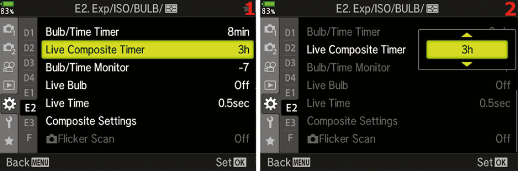
Figure 7.116: Choosing a time for the Live Composite Timer
Use the following steps to choose a time for the Live Composite Timer for long exposures:
- Select Live Composite Timer from the E2. Exp/ISO/BULB/[Meter] menu and scroll to the right (figure 7.116, image 1).
- Use the Arrow Pad up or down keys to choose one of the times from 4min (4 minutes) to 6h (6 hours) (figure 7.116, image 2).
- Press the OK button to Set the value.
Settings Recommendation: This setting really depends on what you are shooting. You need to match the subject with the amount of time needed to capture it. I have it set to 3 hours as the default and then just change it as needed depending on the subject.
Bulb/Time Monitor (E2)
You will normally use the BULB mode to take long exposures in the dark. Therefore, you may want the monitor to be very dim to preserve your night vision.
On the other hand, you may be shooting a one- or two-minute daylight exposure with a neutral-density (ND) filter to hold back the brightness of the exposure and allow a long exposure in normal light. In that case you may want the monitor to be brighter than normal.
The camera allows you to change the brightness of the monitor when using the BULB mode by using the Bulb/Time Monitor function. You can select from –7 to +7 levels of brightness. The factory default is –7 for a very dim monitor. You will see the monitor dim immediately when you select the BULB mode.
Let’s examine how to select the monitor brightness for long exposures.
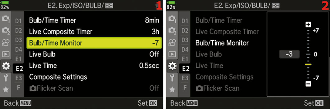
Figure 7.117: Choosing a monitor brightness level for BULB, LIVE BULB, and LIVE TIME
Use the following steps to choose a monitor brightness level when you use the BULB mode for long exposures:
- Select Bulb/Time Monitor from the E2. Exp/ISO/BULB/[Meter] menu and scroll to the right (figure 7.117, image 1).
- Use the Arrow Pad up or down keys to choose one of the 15 brightness levels from –7 to +7 (figure 7.117, image 2). The factory default is –7 (very dim).
- Press the OK button to Set the value.
Settings Recommendation: I do most of my long exposure shooting at night, so I leave this value set to –7. However, if you like to do daytime long exposures with a neutral-density filter, you will want your monitor to be bright. If you select the BULB mode during the day, with this setting at –7, the monitor will be too dim to see in normal daylight. Therefore, set the value in advance.
Live Bulb (E2)
When you use the Live Bulb feature, the display on the back of the camera will update periodically so you can see what is being recorded. Use the Live Bulb function to choose how frequently the monitor displays an updated live exposure view when you use the LIVE BULB shutter speed, or whether the camera shows no live exposure updates when you use BULB (with the Live Bulb function set to Off).
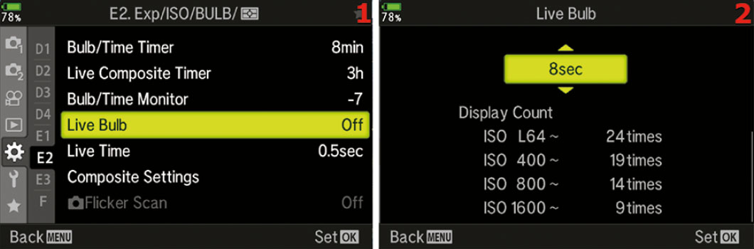
Figure 7.118: Choose how often the live exposure view updates for LIVE BULB time exposures
Use the following steps to choose an update increment for LIVE BULB during long exposures:
- Select Live Bulb from the E2. Exp/ISO/BULB/[Meter] menu and scroll to the right (figure 7.118, image 1).
- Choose one of the values from the up/down menu, ranging from 0.5sec to 60sec (figure 7.118, image 2). The factory default setting is Off for BULB mode (no live exposure updates). If you want to watch the LIVE BULB mode update the screen with a live exposure, you must select how often you want it to update (e.g., 4sec) from the up/down menu. The approximate Display Count (9 times to 24 times) is shown below the up/down menu in image 2.
- Press the OK button to Set the value.
Note: During the long exposure, if you have chosen to see the live exposure update—with Live Bulb set to anything other than Off—you will see the exposure forming on the screen. If you decide the exposure is correct for your subject, either by viewing it directly or by watching the Live histogram display on the screen, you can release the Shutter button and stop the exposure at that moment.
If you have the Noise Reduct. function enabled, the camera will do a noise reduction cycle equal in time to the original exposure. It will generally double the exposure time while using black-frame subtraction to reduce noise.
Settings Recommendation: I want my camera to show a live exposure update, so I set Live Bulb to something like 4sec, or maybe more for a very long exposure. The screen will be updated a maximum of 24 times, so you will need to do some math to calculate an update increment that matches the length of the planned exposure and the number of times the screen is updated.
I try to set the exposure frequency so the screen will update throughout the exposure. For instance, if I am doing a 1min exposure with the LIVE BULB shutter speed setting, at a lower ISO (24 steps) I set the Live Bulb function to 2sec so the camera will update each of the 24 steps every 2 seconds. That means I will see updates on my monitor every 2 seconds until the 24 update steps have completed.
There is a nearly identical function called Live Time (next subsection) that lets you control the updates of the screen when you use the LIVE TIME shutter speed.
Live Time (E2)
As the camera makes an exposure over time and displays the live results of that exposure on your camera’s current display screen (viewfinder or monitor), you can see the actual image being formed.
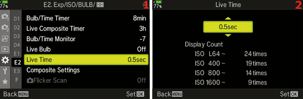
Figure 7.119: Choose how often the live exposure view updates for LIVE TIME long exposures
Use the following steps to choose an update increment for LIVE TIME during long exposures:
- Select Live Time from the E2. Exp/ISO/BULB/[Meter] menu and scroll to the right (figure 7.119, image 1).
- Choose one of the values from the up/down menu, ranging from 0.5sec to 60sec (figure 7.119, image 2). The factory default setting is 0.5sec (1/2 second live exposure updates). If you want to see up to 24 updates per ISO setting, you must select how often you want an update to display from the up/down menu (not Off). The approximate Display Count (9 times to 24 times) is shown below the up/down menu in image 2. During the exposure, you will see the Display Count and a timer on the lower-right side of the screen while a Live histogram appears on the lower-left side of the screen.
- Press the OK button to Set the value.
Note: During the long exposure, if you have chosen to see the live exposure update—with the Live Time function set to anything other than Off—you will see the exposure forming on the screen. If you decide the exposure is correct for your subject, either by viewing it directly or by watching the Live histogram display on the screen, you can press the Shutter button again and stop the exposure at that moment.
If you have the Noise Reduct. function enabled, the camera will do a noise reduction cycle equal in time to the original exposure. It will generally double the exposure time while using black-frame subtraction to reduce noise.
Settings Recommendation: I want my camera to show a live exposure update, so I set Live TIME to a value, such as 2sec or 8sec, according to how long of an exposure is set in the Bulb/Time Timer function.
I try to set the exposure frequency so the screen will update all through the exposure. For instance, if I am doing an 8min exposure at a lower ISO (24 steps), I set the Live Time function to 15sec so the camera will update one of the 24 steps every 15 seconds. That means I will see the updates on my monitor every 15 seconds until the 24 update steps have completed.
Composite Settings (E2)
The Live Composite function allows you to create composite images of subjects like a fireworks display (figure 7.120). You can set up many multiple exposures on one frame, with each exposure acting independently.
The camera will automatically create a composite image as you watch the exposure timer count down. You can recompose the frame between exposures so you can capture multiple bright subjects with dark backgrounds. Figure 7.120 is a composite image that is made up of 10 separate exposures.

Figure 7.120: Sample composite fireworks image
There are two ways to configure the Composite Settings. You can use the Custom Menu first to configure the exposure time and then enter the Live Composite system, or you can enter the Live Composite system first then set the exposure time just before you shoot the frames you want to combine. Let’s consider both.
Setting the Composite Settings before Entering Live Composite
You can configure the exposure time for each frame before you enter the Live Composite system so your camera will be ready ahead of time. Here is how to preconfigure the composite exposure value (applies to each frame).

Figure 7.121: Configuring an exposure value before entering Live Composite mode
Use the following steps to preconfigure an exposure value that will be applied to each frame of the composite image:
- Select Composite Settings from the E2. Exp/ISO/BULB/[Meter] menu and scroll to the right (figure 7.121, image 1).
- Choose an Exposure time per image from the Composite Settings up/down menu (figure 7.121, image 2). Your choices in the up/down menu range from 1/2 second (1/2sec) to 60 seconds (60sec). Choose the time you want to use for each exposure in the composite series.
- Press the OK button to Set your chosen value.
The camera is now ready to enter the Live Composite system and make your composite images.
Next, let’s consider how to set the Exposure time per image when you are already in the Live Composite system.
Setting the Composite Settings after Entering Live Composite
Open the Live Composite system by selecting the LIVECOMP setting when the Mode Dial is set to Bulb (B) by rotating the Rear Dial.
Let’s see how to use the Live Composite system to create an image like the one shown in figure 7.122.

Figure 7.122: Selecting an exposure time while in Live Composite mode
Use these steps to set the Composite Settings after you activate the Live Composite system:
- 1. Set the camera to Bulb (B) mode on the Mode Dial.
- 2. Using the Rear Dial, select LIVECOMP (figure 7.122, image 1, red arrow).
- 3. Press the Menu button to directly enter the Composite Settings screen (figure 7.122, image 2). Choose an Exposure time per image to be applied equally to each frame in the composite image. Your choices in the up/down menu range from 1/2 second (1/2sec) to 60 seconds (60sec).
- 4. Press the OK button to select the exposure time, and the camera will switch to the screen in figure 7.122, image 3. Nothing needs to be done on this screen, so press the Shutter button slightly to return to the first screen in the series (figure 7.122, image 1). The time value is selected and ready to use. The next few steps will take the pictures to be composited.
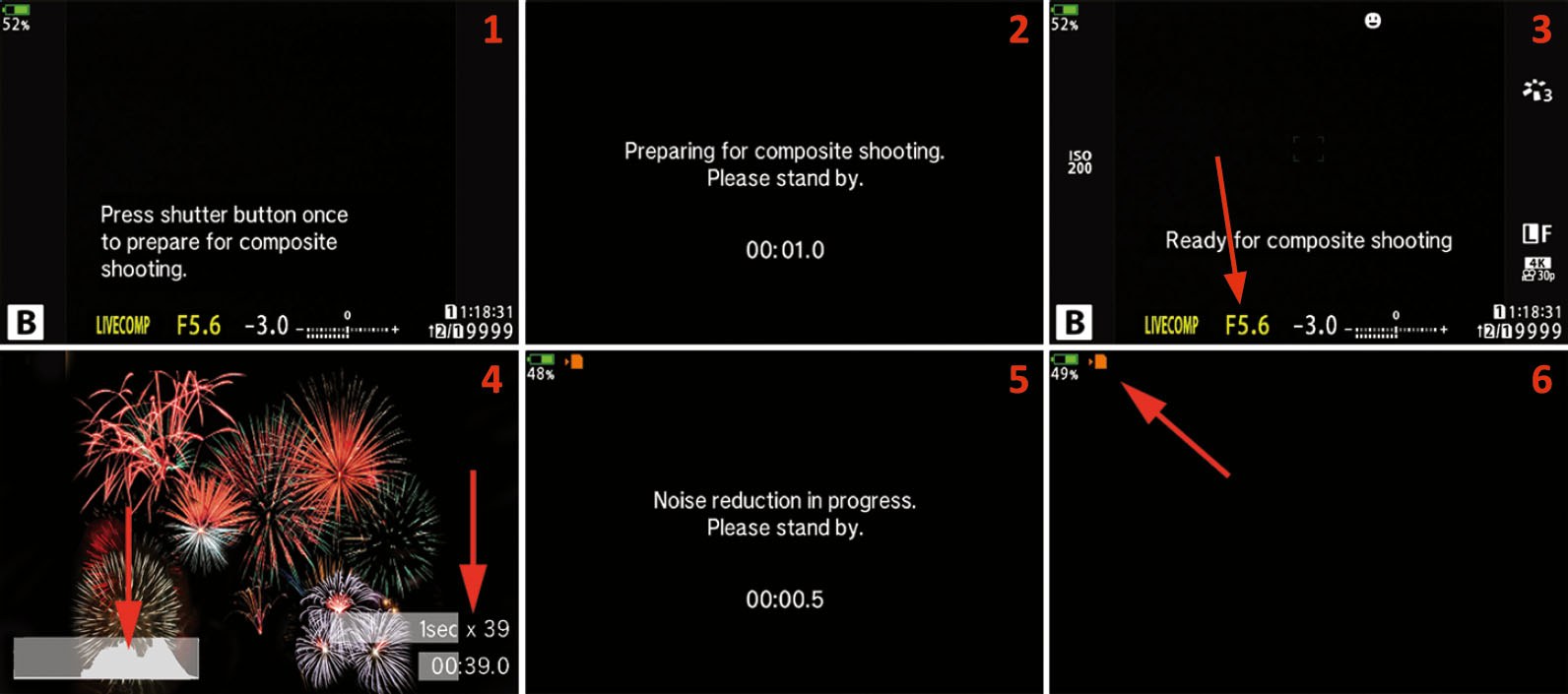
Figure 7.123: Taking pictures with the Live Composite system
- 5. The Live Composite screen (figure 7.123, image 1) will display this message: Press shutter button once to prepare for composite shooting.
- 6. Press the Shutter button all the way down once, and the camera will prepare to take the composite series. A dark screen will open for a few seconds that says, Preparing for composite shooting. Please stand by (figure 7.123, image 2).
- 7. The next screen says, Ready for composite shooting. It will use the settings and exposure value you selected. Before proceeding, use the Front Dial to set the aperture (figure 7.123, image 3, red arrow). Then focus the camera on the subject or on the area where the subject will appear. It may be a good idea to use manual focus for subjects that will appear later in the series, such as a fireworks show. After you have focused the camera, press the Shutter button completely down one time to start the exposures.
- 8. The camera will start taking a series of timed pictures until one of the following occurs: you stop Live Composite by pressing the Shutter button fully; three hours have passed; or the battery dies. Three hours is the maximum run time for the Live Composite system before it automatically shuts down. At the left red arrow in figure 7.123, image 4, you can see that the camera is building a live histogram as it takes the exposures. You can watch this histogram to prevent overexposure as additional images are taken over time. At the right red arrow in image 4, you can see the camera counting down the exposures and time. The image shows 1secx39, which means each exposure is 1 second long (1sec), and 39 exposures have been made so far (x39). Just beneath the exposure count is a timer that displays the actual time of the Live Composite session. The time is counted in 1/2 second increments up to three hours. During the series of exposures, you can move the camera to position a bright subject somewhere else in the frame.
- 9. Stop the Live Composite session by completely pressing the Shutter button once. The monitor will show the noise reduction screen (figure 7.123, image 5), then go black except for the orange memory card access symbol in the upper-left corner, which will blink as the camera finishes combining the images (figure 7.123, image 6). Finally, the camera will display the finished composite picture, according to the value you chose in Setup Menu > Rec View (default 1/2 second), then the camera will switch back to the main Live Composite screen so you can prepare for another session (figure 7.123, image 1).
- 10. If you would like to shoot another Live Composite series, simply repeat steps 3 through 9. If you are done shooting in Live Composite, select a different shutter speed to exit the Live Composite system.
Note: The camera will automatically adjust the brightness of the monitor during a Live Composite session. It may be best to use an HLD-7 battery pack so you will have two batteries available for long exposures if you shoot in Live Composite for hours at a time.
[Camera] Flicker Scan (E2)
This setting tries to remove or minimize banding that can occur when you take photos under LED lighting. This setting will only be available when shooting in S (Shutter-priority) and M (Manual) exposure modes and when using any of the silent drive modes or the High Res Shot or the Pro Capture mode. Turning this on will also reduce the range of available shutter speeds.

Figure 7.124: Turning the Flicker Scan on or off
Use the following steps to turn the Flicker Scan on or off. This menu item will be grayed out if the exposure mode is not set to either M (Manual) or S (Shutter-priority) and the drive mode is not set to one of the Silent modes or High Res Shot or Pro Capture:
- Select Flicker Scan from the E2. Exp/ISO/BULB/[Meter] menu and scroll to the right (figure 7.124, image 1).
- Choose On or Off to activate the Flicker Scan (figure 7.124, image 2). Press OK to Set your choice.
Settings Recommendation: If you find yourself dealing with banding under LED lights, try changing this to On and see if it helps. I have not had any instances where this has been an issue, but it is nice to know that if this does occur, there is a solution or at least a setting that might make it better.
Metering (E3)
The E-M1III has five meter types, which gives you great flexibility in how you expose your images. Let’s look more closely at the five types of light meters built into the camera and discuss their differences:
- [Digital ESP Metering]: ESP stands for electrosensitive pattern. The camera meters the image in a grid of 324 metered areas. It examines each of the 324 areas and uses complex mathematical computations to arrive at an excellent exposure most of the time.
- [Center-Weighted Averaging Metering]: The camera averages the light between the subject and the background. It places more emphasis on the center area of the screen with less emphasis on parts of the scene that are at the edges. You will see a mediumsized circle in the middle of the monitor. The circle does not represent the actual size of the averaging meter’s metering area.
- [Spot Metering]: The camera uses a small circle in the center of the frame for metering. This circle is equivalent to 2 percent of the frame. All metering takes place in this 2 percent area. Therefore, you must place this non moveable spot on the area of the subject that you want to correctly meter by moving the camera, and then using autoexposure lock (AEL/AFL button) to lock the exposure while you recompose the image (see the next subsection, AEL Metering).
- [Spot Metering—Highlight (HI)]: This type of metering is similar to [Spot Metering] in that the camera uses a small circle in the center of the frame to meter. This circle is equivalent to 2 percent of the frame. This metering mode is different because the camera tries to make white areas (highlights) stay white by increasing the exposure beyond a [Spot Metering] reading to give a bright, high-key look to the image.
- [Spot Metering—Shadow (SH)]: This type of metering is similar to [Spot Metering] in that the camera uses a small circle in the center of the frame to meter. This circle is equivalent to 2 percent of the frame. This metering mode is different because the camera tries to make dark areas (shadows) stay dark by decreasing the exposure below a [Spot Metering] reading to give a low-key look to the image.
Now let’s examine how to select one of the metering types.

Figure 7.125: Choosing a light meter type
Use the following steps to choose a Metering type:
- Select Metering from the E3. Exp/ISO/BULB/[Meter] menu and scroll to the right (figure 7.125, image 1).
- Select one of the five meter types shown in the menu (figure 7.125, image 2).
- Press the OK button to Set the value.
Settings Recommendation: I usually use [Digital ESP Metering]. I like the way it evaluates all areas of the screen and arrives at an excellent exposure. However, I have found that it is best to use Face Priority along with this meter type to have the best exposure for portraiture.
There is a meter type for each of us: the [Center-Weighted Averaging Meter] is good for old-timers who like this traditional meter style. The three types of [Spot Metering] allow extremely accurate metering of specific areas of a subject for those who understand how to use a spot meter. The highlight and shadow meters add icing to the cake.
I suggest experimenting with all these meter types until you are familiar with them.
AEL Metering (E3)
When you press the AEL/AFL button with the camera configured for autoexposure lock, the camera makes a meter reading then locks the exposure until you release the AEL/AFL button. Olympus has provided a means for you to choose which type of meter your camera will use to make the exposure reading that will be locked.
There are five AEL Metering modes:
- Auto: When you press the AEL/AFL button, the camera uses whichever metering mode you selected in the Metering subsection. This is the factory default setting, and it is apparently the only way to access [Digital ESP Metering] for autoexposure lock.
- [Center-Weighted Averaging Metering]: When you press the AEL/AFL button, the camera switches to [Center-Weighted Averaging Metering], as described in the Metering subsection.
- [Spot Metering]: When you press the AEL/AFL button, the camera switches to [Spot Metering], as described in the Metering subsection.
- [Spot Metering—Highlight (HI)]: When you press the AEL/AFL button, the camera switches to [Spot Metering—Highlight (HI)], as described in the Metering subsection.
- [Spot Metering—Shadow (SH)]: When you press the AEL/AFL button, the camera switches to [Spot Metering—Shadow (SH)], as described in the Metering subsection.
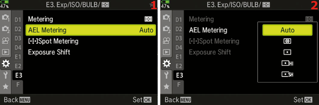
Figure 7.126: Choosing a metering mode for autoexposure lock
Use the following steps to choose a Metering type when you press the AEL/AFL button:
- Select AEL Metering from the E3. Exp/ISO/BULB/[Meter] menu and scroll to the right (figure 7.126, image 1).
- Select one of the five meter types shown in the menu (figure 7.126, image 2).
- Press the OK button to Set the value.
Settings Recommendation: The Auto mode seems to be the most reasonable setting for me. I normally have the best light meter type already selected before I use autoexposure lock.
However, maybe you are metering a beautiful sunset and decide to use autoexposure lock to meter a bright orange cloud. You might want to use [Spot Metering]. If you already had the AEL Metering function set to [Spot Metering], you would be ready to shoot. You could meter the bright cloud, recompose, take the shot, then continue shooting with [Digital ESP Metering] for more images of other subjects. In cases like this it may be wise to separate the Metering types when you use normal metering and after pressing the AEL/AFL button.
[AF Target] Spot Metering
The E-M1III allows you to tie the spot metering (and spot highlight and spot shadow metering) to the currently selected AF Target area. This makes a lot of sense, as you would think the area of focus would also be the area where you want to measure the light.
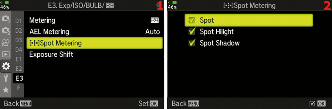
Figure 7.127: Metering the selected AF Target
Use the following steps to enable spot metering for the selected AF Target:
- Select [AF Target] Spot Metering from the E3. Exp/ISO/BULB/[Meter] menu and scroll to the right (figure 7.127, image 1).
- Place a check mark next to each spot metering type by highlighting it and pressing the OK button (figure 7.127, image 2).
- Once you have made your selections, press the Menu button to return to the previous screen.
Settings Recommendation: I always tie the focus point to the spot metering so that the camera meters the most important area of the scene.
Exposure Shift (E3)
If you think one of your camera light meters (Digital ESP, Center Weighted, Spot) needs a little fine-tuning, you can use this function to set up a semipermanent exposure compensation for individual light meter types.
For instance, if you usually shoot with the Digital ESP meter and you want the meter to add a half stop of exposure beyond the default, you can set it up with this function.
The camera allows you to fine-tune each light meter type in 1/6-stop (1/6 EV step) increments, up to one full stop over- or underexposed.

Figure 7.128: Fine-tuning the camera’s exposure meters
Use these steps to set up a semipermanent Exposure Shift on any or all of the three light meter types:
- Select Exposure Shift from the E3. Exp/ISO/BULB/[Meter] menu and scroll to the right (figure 7.128, image 1).
- The top meter selection is the Digital ESP meter. The second meter type is the Center Weighted meter, and the third meter type is the Spot meter (figure 7.128, image 2). Let’s use the Digital ESP meter as an example of how to set up an Exposure Shift of 1/2 stop (+3/6). The process is the same for all meter types, so you can use these steps for whichever meter you want to fine-tune. Choose the meter you want to modify and scroll to the right.
- In figure 7.128, image 3, the Digital ESP meter is selected and the Exposure Shift menu is open. Use the Arrow Pad keys to select from +1/6 to +1 stop of Exposure Shift in 1/6 stop increments. In image 3, you can see that I selected +3/6 EV steps (1/2 stop). The camera will add 1/2 stop of exposure compensation and mildly overexpose the image.
- After you have selected how much you want to shift the exposure, press the OK button to lock in the Exposure Shift setting. Repeat these steps for any other meter type that you want to adjust.
Note: The Exposure Shift function is a form of exposure compensation. It is applied semipermanently; that is, it stays in place until you go back to the Exposure Shift function and remove the shift value. When you shift the exposure for any of the light meters, you may find that you do not have the normal range of exposure compensation after you adjust the meter.
Also, you will not see the effects of the Exposure Shift in the EVF or on the rear monitor, although you will be able to detect it in the image histogram.
Settings Recommendation: I have found that the exposure meters in the E-M1III are very accurate, and I am quite satisfied with their performance. However, you may be shooting a style of photography that easily fools your light meter. In that case, experiment with this function to see if it will help overcome the exposure problem. Don’t forget that Exposure Shift is in place or you may find that your images are regularly over- or underexposed.
Custom Menu F. [Flash] Custom
The F. [Flash] Custom menu is composed of functions that directly affect how the flash system works. First we will take a look at the opening menu screen for the F. [Flash] Custom functions (figure 7.129).
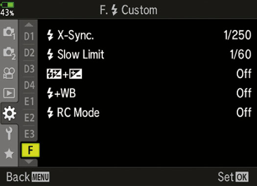
Figure 7.129: F. [Flash] Custom functions
To enter the menu, select F. [Flash] Custom from the Custom Menu and scroll to the right. There are five functions in the F. [Flash] Custom menu. Let’s consider each of them in detail.
[Flash] X-Sync (F)
The [Flash] X-Sync function sets a maximum shutter speed for shooting with an electronic flash unit that is mounted in the hot shoe and turned on.
The X-Sync speed is necessary because the shutter blades in front of the sensor have to be out of the way before the flash can fire. If a shutter blade partially blocks the sensor, a dark shadow or band will appear in the image.
The E-M1III allows you to select an X-Sync speed from 1/60 second to 1/250 second. The [Flash] X-Sync function controls the fastest, or maximum, shutter speed you can use with flash (without banding). The next subsection will consider the [Flash] Slow Limit, which controls the slowest, or minimum, shutter speed you can use with flash in certain exposure modes. You can use the two functions—[Flash] X-Sync and [Flash] Slow Limit—to control the upper and lower limits of the shutter speed when you use flash to get a mixture of flash light and ambient light. We will discuss how to blend the two types of light in the next subsection, [Flash] Slow Limit.
The camera will use the maximum X-Sync value only when you are shooting in a very bright environment in direct flash (Fill In) mode to prevent the ambient light from overly influencing the exposure. Most of the time, in low ambient light, the camera will automatically select a somewhat slower shutter speed, such as 1/60 second, unless you have [Flash] Slow Limit (next subsection) set so it cannot use a speed that low.
Let’s examine how to select an X-Sync value that matches your needs.

Figure 7.130: Selecting an X-Sync value
Use the following steps to choose a maximum shutter speed to use with flash:
- Select [Flash] X-Sync from the F. [Flash] Custom menu and scroll to the right (figure 7.130, image 1).
- Use the Arrow Pad up/down keys to choose one of the brightness levels, which range from 1/60 to 1/250 (figure 7.130, image 2). The factory default setting is 1/250 second.
- Press the OK button to Set the value.
Settings Recommendation: I normally use 1/250 second for the X-Sync value when I am depending on the flash unit for lighting a subject. However, when I am trying to synchronize flash with evening light outdoors, I may use a combination of the [Flash] X-Sync speed and [Flash] Slow Limit to allow ambient light to influence the exposure for a more balanced look. The camera has a nice range of shutter speeds for slow flash use.
[Flash] Slow Limit (F)
The [Flash] Slow Limit function allows you to control the lower shutter speed limit when you use flash photography (slow flash). You may need this function when you want ambient light combined with light from a flash unit to illuminate the exposure. You may want ambient light to be the primary source of exposure, with the flash providing a little fill light. Or you may want the flash to provide the main illumination, with ambient light opening up the shadows in the background. You may even be using more than one flash in a wireless group of units that work with ambient light.
[Flash] Slow Limit works in partnership with the [Flash] X-Sync function (previous subsection) by allowing you to set the lower limit of the shutter speed when you shoot with flash. The shutter speed can be as slow as 30 seconds. The [Flash] X-Sync function controls the upper shutter speed limit, which cannot exceed 1/250 second and can be set as slow as 1/60 second.
When you have the camera set to Program (P) or Aperture-priority (A) mode on the Mode Dial, the camera controls the shutter speed and you control the aperture. Therefore, the lower shutter speed limit provided by the [Flash] Slow Limit function is important when you are using flash in P and A modes.
If you are using Shutter-priority (S) or Manual (M) mode on the Mode Dial, the [Flash] Slow Limit function has no effect because you can set the lower shutter speed to be as long (slow) as you would like.
Therefore, if you want to balance the illumination from the flash and the ambient light, you can either do it manually in S or M mode, or you can use P or A mode and depend on the [Flash] Slow Limit function to provide the minimum flash shutter speed.
To effectively balance the ambient light with the flash requires experimentation and experience and is beyond the scope of this book. You know that the camera cannot exceed 1/250 second for a maximum shutter speed ([Flash] X-Sync), and now you also know that the camera will allow you to set a minimum shutter speed ([Flash] Slow Limit). Therefore, you can use mostly ambient light by lengthening the shutter speed with a slower setting under [Flash] Slow Limit to let in more ambient light while the flash provides a burst of light for filling in some shadows.
Or you can use a shutter speed in [Flash] Slow Limit that is somewhat closer to the shutter speed in [Flash] X-Sync so the flash will provide the main light source while ambient light provides some background fill.
You will need to experiment with these two settings to find the appropriate balance for what you are trying to accomplish. Be sure to use a tripod if you use shutter speeds in [Flash] Slow Limit that are slow enough to allow camera shake or subject movement. Otherwise, ghosting will be apparent in the image where the flash-lit portion of the subject is sharp and the ambient-lit portion of the subject is blurred.
Let’s examine how to set the [Flash] Slow Limit function for various shutter speeds.

Figure 7.131: Setting a minimum shutter speed for flash photography
Use the following steps to choose a minimum shutter speed to use with flash:
- Select [Flash] Slow Limit from the F. [Flash] Custom menu and scroll to the right (figure 7.131, image 1).
- Use the Arrow Pad up/down keys to choose a minimum flash shutter speed, ranging from 30 seconds to 1/250 second (figure 7.131, image 2). The factory default setting is 1/60 second.
- Press the OK button to Set the value.
Settings Recommendation: I raise the minimum flash shutter speed to 1/100 or 1/125 second when I am shooting with flash indoors. I find that often 1/60 second (the default) is too slow and may allow some ghosting to occur, especially at weddings where I am shooting people walking down the aisle when fairly bright ambient light influences the exposure. If the shutter is open for 1/60 second, the flash will make a nice sharp picture for a short segment of the exposure duration, and ambient light continues to illuminate the subject for the remainder of the exposure duration, resulting in a ghosted blur.
On the other hand, when I am shooting in bright ambient light outside, I may allow the shutter speed to remain slower and take advantage of some ambient light with flash fill. I use a smaller aperture to keep from overexposing the subject.
This type of thing is always an experiment and has to be balanced. You can take advantage of your camera’s powerful tools to get the results you want.
[Flash Compensation] + [Exposure Compensation] (F)
This function allows you to combine exposure compensation and flash compensation, and you can control both at the same time with the Front Dial.
Normally, with this function set to Off, when you want to do exposure compensation for your image, you simply turn the Front Dial (in P, A, and S modes) and dial in exposure compensation from –5.0 EV to +5.0 EV.
However, when you have a flash unit mounted on your camera, its output is not increased or decreased based on the exposure compensation. Instead, the camera simply opens or closes the aperture, or raises or lowers the shutter speed, to provide more or less exposure. The flash provides a constant output.
Sometimes increasing or decreasing the entire exposure is not sufficient. Maybe you would like to increase or decrease the power of the flash output to perform what Olympus calls “flash intensity control.” By setting this function to On, whenever you turn the Front Dial to increase or decrease the camera exposure compensation, the compensation request also affects the flash unit. For example, if you raise the exposure compensation by 1.0 EV, the flash will also raise its power output by 1.0 EV. If you use negative exposure compensation to underexpose the image by 0.3 EV, the flash will also lower its power output by 0.3 EV.
This gives you the ability to control the intensity of the flash output very quickly, without having to use the flash unit’s compensation controls. It allows you to raise or lower the brightness of the subject visually in case the flash is too strong or too weak.
Basically, Olympus gives you flash intensity control without having to use the camera menus or external flash unit menus. It is a quick way to control the intensity of the flash with the Front Dial when you need more or less light from the flash unit, and you’ll still have time to make other adjustments.
Let’s examine how to enable or disable [Flash Compensation] + [Exposure Compensation].
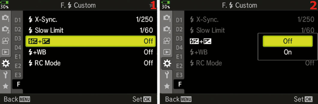
Figure 7.132: Combining flash compensation with exposure compensation
Use the following steps to connect or disconnect flash compensation with exposure compensation by using the Front Dial:
- Select the dual symbols representing [Flash Compensation] + [Exposure Compensation] from the F. [Flash] Custom menu and scroll to the right (figure 7.132, image 1).
- Choose On to combine flash and exposure compensation, or choose Off to disconnect the two (figure 7.132, image 2). The factory default setting is Off. This function takes effect only when a flash unit is mounted in the hot shoe.
- Press the OK button to Set the value.
Settings Recommendation: I leave this function set to On because I love the way it lets me control the intensity of the flash when I turn the Front Dial on my camera in P, A, and S modes. Since it has no effect when a flash unit is not mounted, it is safe to leave it on all the time.
If you are an accomplished strobist who wants to completely separate the two forms of compensation to vary the exposures for the background and the subject, you may want to leave flash and exposure compensation separated and use the camera’s and flash unit’s manual exposure compensation controls.
For most people the power of this function is very useful.
[Flash] + WB (F)
This function allows you to choose various white balance (WB) types for when you use electronic flash. There are three settings for [Flash] + WB that determine what the camera will do when the flash is active:
- Off: The camera will use the current WB setting (e.g., Sunshine, Cloudy, Incandescent) without regard for the color temperature of the flash unit.
- WB Auto: The camera will attempt to balance itself to whatever light source is illuminating the subject.
- WB [Flash]: The camera will use the Flash WB setting, which is about 5500K.
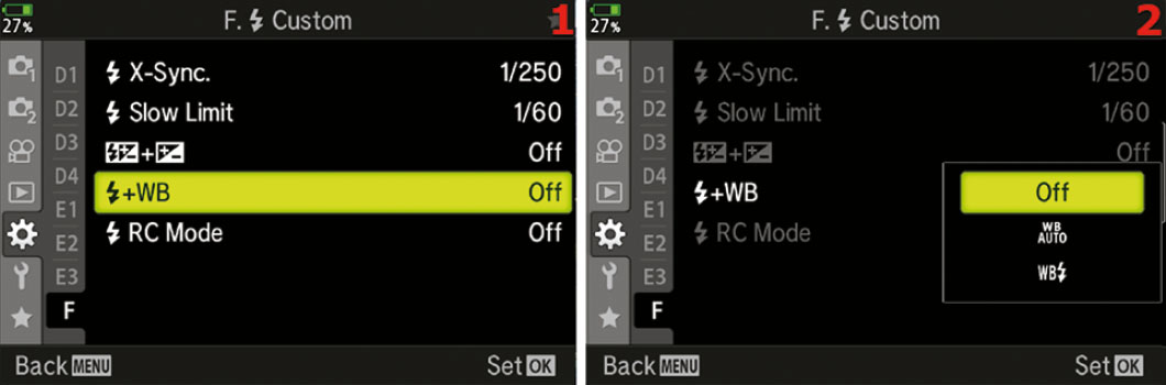
Figure 7.133: White balance choices for flash
Use the following steps to choose an appropriate WB setting for flash:
- Select the [Flash] + WB function from the F. [Flash] Custom menu and scroll to the right (figure 7.133, image 1).
- Choose one of the settings from the [Flash] + WB menu (refer to the previous list of choices) (figure 7.133, image 2).
- Press the OK button to Set your choice.
Settings Recommendation: If you are shooting in JPEG mode, the WB needs to be exactly right. Be careful to select the WB Flash setting from the Live Control screen (press OK in Live View) or the WB [Flash] setting on this function’s menu.
Alternatively, you can let the camera decide which WB is best by selecting WB Auto. It may not be the best idea to have a WB setting such as Cloudy or Fluorescent selected while shooting with flash because the color may be off.
For RAW shooters, this setting does not matter since the WB of a RAW file can be changed after the fact.
[Flash] RC Mode (F)
This function allows for the use of wireless remote-controlled flash units controlled by the flash on the camera. Wireless flash photography is available with Olympus flashes that support wireless remote control (RC). The settings for the camera-mounted flash unit and three wireless groups can all be adjusted right from the camera as long as the RC mode is active on all the flash units. To have this all work, you need to use this menu to turn the flash RC mode on. When this mode is active, you will see the RC mode super control panel, which allows you to set the Flash control mode, the flash compensation, the flash mode, the optical signal strength, and the channel for the A, B, and C groups, along with the flash mounted to the camera (figure 7.134).
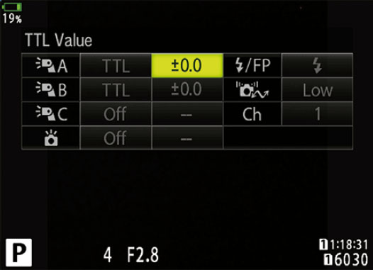
Figure 7.134: The RC mode super control panel

Figure 7.135: The [Flash] RC Mode menu
Use the following steps to turn the RC mode on or off:
- Select the [Flash] RC Mode from the F. [Flash] Custom menu and scroll to the right (figure 7.135, image 1).
- Choose On to activate the RC mode or Off to turn the RC mode off (figure 7.135, image 2).
- Press the OK button to Set your choice.
Settings Recommendation: The wireless remote control ability of the camera is a real leap forward as it allows for multiple small flash units to be used together to create complex lighting without the need for any cables or extra gear, other than compatible flashes.
Custom Menu G. [Record Mode]/WB/Color
The G. [Record Mode]/WB/Color menu is primarily composed of functions that control JPEG image quality, image size, and color balance.
These functions do not affect a RAW file, other than providing initial settings when you view them on your computer, because each setting can be changed after the fact.
Think of these options as in-camera RAW to JPEG conversion functions (in-camera postprocessing) that you would otherwise have to do on your computer after you shoot a RAW file and convert it to JPEG manually.
We will start examining the functions by taking a look at the opening menu screen for the G. [Record Mode]/WB/Color functions in figure 7.136.
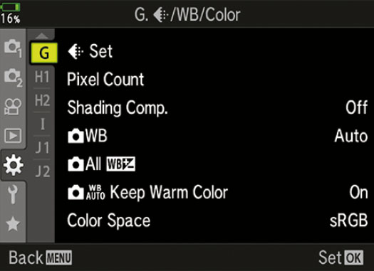
Figure 7.136: The G. [Record Mode]/WB/Color menu
To enter the menu, select G. [Record Mode]/WB/Color from the Custom Menu and scroll to the right. There are seven functions inside the G. [Record Mode]/WB/Color menu. Let’s consider each of them in detail.
[Record Mode] Set (G)
Your E-M1III can create three JPEG image sizes: Large (L), Middle (M), and Small (S). All three sizes can use three levels of compression (quality) to reduce the file sizes: Super Fine (SF), Fine (F), and Normal (N). Each of these quality types have different lossy compression ratios, with Super Fine having the least amount of compression and Normal having the most (table 7.1).
You can combine JPEG types in the [Record Mode] Set function and they will appear on the [Record Mode] menus of the camera where you select an image format (i.e., JPEG, RAW, JPEG+RAW).
Table 7.1 shows the available JPEG sizes and qualities, compression ratios, and Pixel Counts. The Pixel Count for the Middle and Fine JPEG sizes is controlled by the Pixel Count function (next subsection):
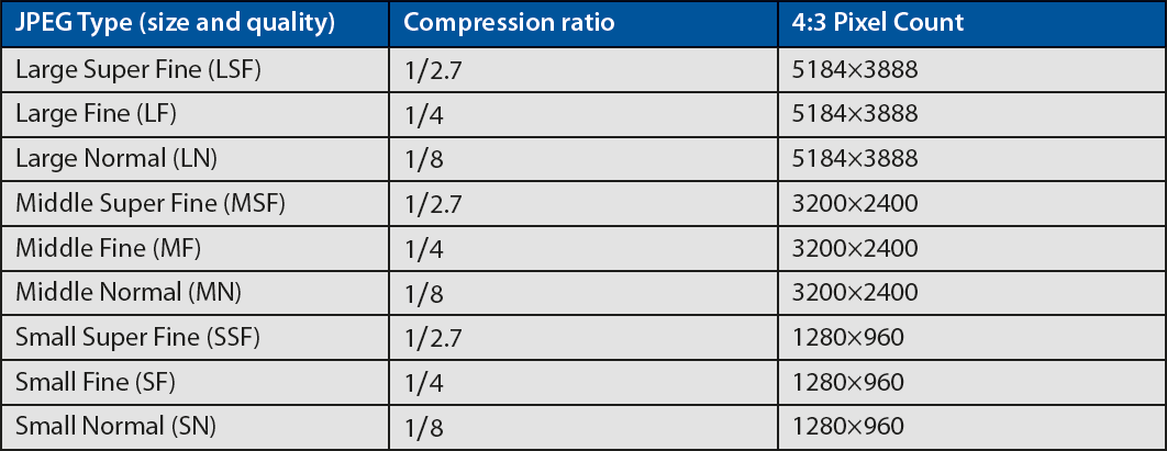
Table 7.1: JPEG size and quality, compression ratio, and 4:3 Pixel Count
The lower the compression ratio, the higher the image quality and the larger its physical storage size on your computer hard drive. You can add any of these JPEG size and quality settings to the 1, 2, 3, and 4 positions of the screen shown in figure 7.137, image 2. Let’s see how.
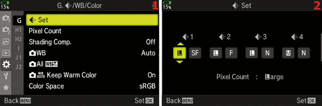
Figure 7.137: Using [Record Mode] Set to choose JPEG types for camera menus
Use the following steps to set various JPEG types in four available selection positions:
- Select [Record Mode] Set from the G. [Record Mode]/WB/Color menu and scroll to the right (figure 7.137, image 1).
- In figure 7.137, image 2, you will see four available JPEG type selection boxes, numbered 1, 2, 3, and 4. The factory default is LSF, LF, LN, and MN. Using table 7.1 as a reference, choose any of the characters from the values in parentheses under the JPEG Type column and set them in these four positions. Whatever you put in the four positions will appear on any camera menus that allow you to select an image format type (JPEG, RAW, and JPEG+RAW).
- Press the OK button to Set the value.
Settings Recommendation: I have no need for the smaller sizes, so I use the default settings here. I prefer to shoot in either RAW or JPEG Large Super Fine (LSF) most of the time.
However, if you need to put a lot of images on a small memory card, or if you are shooting images for use on a website, you could use any of the other size and quality settings. Anything you choose in [Record Mode] Set will appear on the Record Mode menus (image format selection screens).
Pixel Count (G)
The normal Pixel Count for a Micro Four Thirds (4:3) image on the E-M1III is 5184×3888. This is considered the Large Pixel Count size. The Pixel Count directly affects the megapixel size of the image. Simply multiply the Pixel Count to find the total megapixels. For instance, the large 4:3 Pixel Count results in an approximate size of 20 MP (5184×3888 = 20,155,392, or 20.1 million pixels).
Note: There are other Image Aspects (aspect ratios) and Large Pixel Counts available, such as 3:2, 1:1, and 16:9. When you select one of the alternate Image Aspect ratios, the Pixel Count for their Middle and Small sizes will vary a bit from those listed. The additional image sizes are controlled by the Image Aspect function in Shooting Menu 1 (Shooting Menu 1 > Image Aspect). Selecting one of the other aspect ratios will change the Pixel Count for Large, Middle, and Small JPEG images. None of the Large size Pixel Counts are variable, but the Middle and Small Pixel Counts are. The Middle and Small Pixel Count can change depending on your selections in this function.
Let’s examine how to choose a different Pixel Count for when you need to shoot a Middle or Small image, such as for a website. First we will examine how to select one of the two available Middle Pixel Counts.
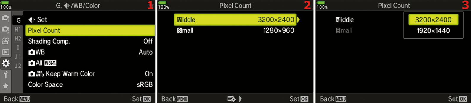
Figure 7.138: Choosing a Middle Pixel Count size
Use the following steps to choose a Middle Pixel Count size:
- Select Pixel Count from the G. [Record Mode]/WB/Color menu and scroll to the right (figure 7.138, image 1).
- Choose Middle from the Pixel Count menu and scroll to the right (figure 7.138, image 2).
- The factory default Middle Pixel Count is 3200×2400 (figure 7.138, image 3). However, you can choose 1920×1440 if wanted.
- Press the OK button to Set the new Middle Pixel Count value.
Next let’s examine how to select one of the two available Small Pixel Counts.
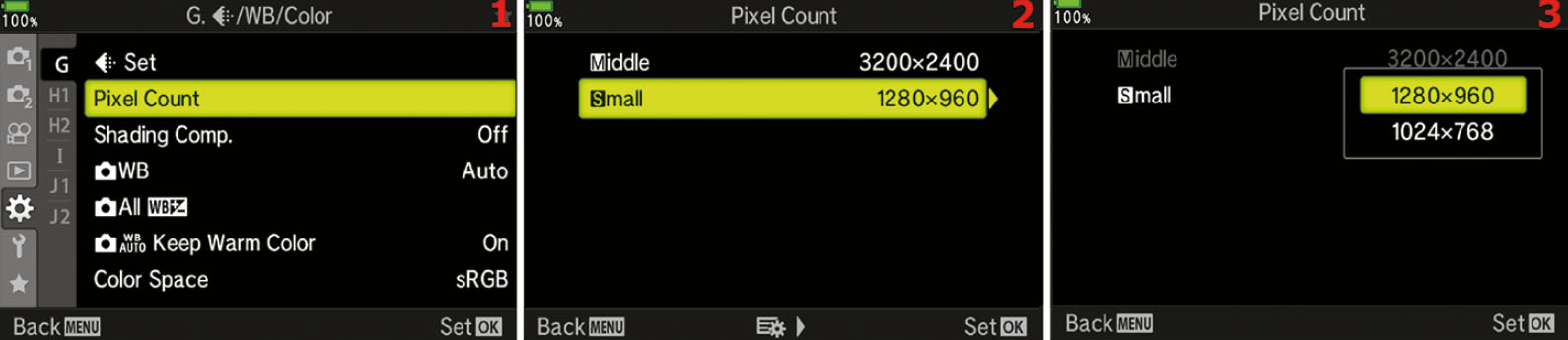
Figure 7.139: Selecting the Small Pixel Count size
Use the following steps to choose a Small Pixel Count size:
- Select Pixel Count from the G. [Record Mode]/WB/Color menu and scroll to the right (figure 7.139, image 1).
- Choose Small from the Pixel Count menu and scroll to the right (figure 7.139, image 2).
- The factory default Small Pixel Count is 1280×960 (figure 7.139, image 3). However, you can choose a smaller Pixel Count: 1024×768.
- Press the OK button to Set the new Small Pixel Count value.
Settings Recommendation: Since I rarely stray from Large Pixel Count because I want to use every available pixel for maximum image size, I don’t often select Middle or Small Pixel Count sizes.
However, some sizes exactly fit, or are very close to, HDTV, computer monitor, tablet, and smartphone sizes. If you shoot specifically for these devices, other Pixel Count sizes may come in handy.
Shading Comp. (G)
With many lenses, there can be some light falloff at the edges of the frame. Certain wide-angle lenses have this issue. In fact, most lenses have a little light falloff in the peripheral areas—that’s just the laws of physics at work. Normally you can correct this problem during post-processing on a computer, especially for RAW files.
However, you may not have the time or inclination to post-process images, so the camera offers a solution. If you have lenses that are especially prone to light falloff, you can enable Shading Comp. and let the camera correct the peripheral dimness for you.
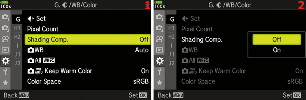
Figure 7.140: Changing the Shading Comp. setting
Use the following steps to enable or disable the Shading Comp. function:
- Select Shading Comp. from the G. [Record Mode]/WB/Color menu and scroll to the right (figure 7.140, image 1).
- Choose Off or On from the Shading Comp. menu (figure 7.140, image 2). If you choose On, the camera will correct for light falloff automatically, according to the type of lens you are using.
- Press the OK button to Set the value.
Note: Brightening the edges of the image can lead to a little additional noise in those areas. Shading Comp. does not work for teleconverters and extension tubes.
Settings Recommendation: I have found that many Micro Four Thirds lenses are already corrected for light falloff problems, and I usually make any needed corrections when I postprocess my RAW images in Photoshop. Therefore, I don’t often use this function.
However, this is a useful function, especially for JPEG shooters. Try it for any lenses that may have light falloff issues and see if it helps.
[Camera] WB (G)
Normally white balance (WB) is used to adjust the camera so that items that are white in your images are rendered white and other colors are also accurate under a given light source. You can also use the WB controls to deliberately introduce color casts into your image for interesting special effects. The WB system adds color to make up for a deficit of color caused by the type of light illuminating the subject.
For instance, fluorescent light lacks blue, which makes the subject appear greenish yellow. When blue is added, the image is balanced to a more normal appearance. Another example is when you shoot on a cloudy, overcast day. The cool ambient light could cause the image to look bluish. The Auto WB control in your camera sees the cool color temperature and adds some red to warm up the colors a bit.
To photographers, blue seems cool and red seems warm!
White Balance Fundamentals
Understanding WB in a fundamental way is simply realizing that light has a range of colors that go from cool to warm. We can adjust our cameras to use the available light in an accurate and neutral, balanced way that compensates for the actual light source. Or we can allow a color cast to enter the image by unbalancing the settings. In this chapter, we will discuss this from the standpoint of the E-M1III controls and how they deal with WB.
Using the WB Function
The E-M1III WB range varies from a very cool 2000K to a very warm 14,000K. What does that mean?
Figure 7.141 shows the same picture adjusted in Photoshop, with the use of photo filters, to three WB Kelvin (K) settings. Notice how the image in the center is about right, the image on the left is cooler (bluish cast), and the image on the right is warmer (reddish cast).

Figure 7.141: One image with three WB Color Temperature settings
The same adjustments we made in the good old days with film and filters can now be achieved with the WB settings built in to the E-M1III. To achieve the same effect as daylight film and a warming filter, simply select the Cloudy WB setting while shooting in normal daylight. This sets the E-M1III to balance at about 6000K, which makes nice warm-looking images. If you want to really warm up the image, choose the WB called Shade, which sets the camera to 7500K.
On the other hand, if you want to make the image appear cool or bluish, try using the Fluorescent (4000K) or Incandescent (3000K) settings in normal daylight.
Remember, the color temperature shifts from cool values to warm values. The E-M1III can record your images with any color temperature from 2000K (very cool or bluish) to 14,000K (very warm or reddish) and any major value in between. There is no need to carry different film emulsions or filters to deal with the range of color in light. The E-M1III has easy-to-use color temperature controls.
Normally you will set the WB from the Live Control screen by pressing the OK button while in Live View. However, you can also use this WB function to set the WB and even fine-tune it (add a color bias).
Here is a list of the 13 WB types you will find on the WB selection screen. Note that six of the WB symbols are followed by a number, such as 5300K. This is the color temperature value for that particular WB setting. We will also discuss how to do an ambient WB reading.
- Auto: Camera automatically chooses the best WB setting
- [Sunlight] 5300K: Direct sunlight pictures
- [Shade] 7500K: Shooting in the shade
- [Cloudy] 6000K: Taking pictures on an overcast day
- [Incandescent] 3000K: Shooting under an old-fashioned lightbulb
- [Fluorescent] 4000K: Making pictures under fluorescent light
- [Underwater]: Taking pictures with your E-M1III while underwater (in a waterproof underwater housing)
- [Flash] 5500K: Making images with an electronic flash unit providing the main light source
- [One-Touch Capture WB] 1: Set and store WB with ambient light reading of a white or gray card (must use the Live Control screen to do the reading)
- [One-Touch Capture WB] 2: Set and store WB with ambient light reading of a white or gray card (must use the Live Control screen to do the reading)
- [One-Touch Capture WB] 3: Set and store WB with ambient light reading of a white or gray card (must use the Live Control screen to do the reading)
- [One-Touch Capture WB] 4: Set and store WB with ambient light reading of a white or gray card (must use the Live Control screen to do the reading)
- CWB (Custom White Balance): Choose a WB color temperature manually, from a range of 2000K to 14,000K
First, let’s consider how to do a One-Touch Capture WB reading.
One-Touch Capture WB Reading
For the most accurate WB, it is best to do an ambient light reading from a white or gray card under the same light source as your subject. This will adjust the camera to use the correct WB while you are under that light source. Be sure to set the WB back to Auto or do a new ambient light reading if the light source changes.
In the E-M1III user’s manual, Olympus calls an ambient light WB reading both One-Touch WB and Capture WB. Therefore, I am combining the two and calling it a One-Touch Capture WB reading or simply a Capture WB reading. Your camera has four memory locations to store WB readings. If you shoot a lot under a certain light source, you can store a Capture WB reading in one location and use it again later.
Let’s examine how to do a Capture WB reading. Use a white or gray card if you have one; otherwise, you can use a blank sheet of white printer paper.
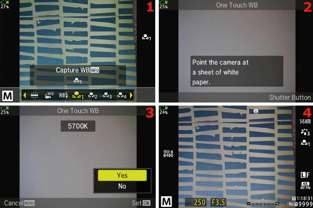
Figure 7.142: Making a One-Touch Capture WB reading from a white card
Use the following steps to do a One-Touch Capture WB reading from a white or gray card:
- Press the OK button while in Live View to open the Live Control screen. Find the WB function on the right side by scrolling up or down with the Arrow Pad. After you have selected the WB function (figure 7.142, image 1), scroll to the left or right with the Arrow Pad until you highlight one of the Capture WB memory locations. In figure 7.142, image 1, I selected memory location 1 (looks like a flower with number 1 to the right of it). You have chosen where you are going to store the WB reading and are now ready to take the ambient light reading from the card.
- Press the INFO button to open the One Touch WB screen. As instructed on the screen in figure 7.142, image 2, place the white card or paper under the light source you want to measure, then press the Shutter button all the way down as if you are taking a picture of it. The camera will fire the shutter and measure the color temperature of the light source that reflects from the card.
- A WB reading is ready to be stored in the current Capture WB memory location; however, you must approve it first by scrolling up and selecting Yes from the menu then pressing the OK button (figure 7.142, image 3). If you do not like the reading, select No to cancel and repeat steps 1 and 2. If you approve of the WB reading, it will be stored in the memory location for immediate use and later recall. You can select it on the Live Control screen or within the WB function (this function).
- After you have approved the WB reading and pressed the OK button, the camera switches to the normal Live Control screen, with the new WB in place. You can tell by looking at the Live View screen in figure 7.142, image 4, that the camera successfully adjusted the WB under the ambient, incandescent light source so that whites look white and other colors look the same as in real life.
Note: In addition to doing a One-Touch Capture WB reading, you can select any of the 13 available White Balance choices from the Live Control screen (figure 7.142, image 1). Using the Live Control screen is much faster than scrolling down to the Custom Menu and selecting the WB function to choose a WB setting.
You must use the Live Control screen to do a One-Touch Capture WB reading, but you cannot adjust the amber–blue (A–B) and green–magenta (G–M) color balance of an individual WB setting. You must use the WB function to fine-tune the A–B and G–M color balance for an individual WB setting, but you cannot do a One-Touch Capture WB reading from the WB function.
Even though the 13 Live Control White Balance settings and the 13 Custom Menu White Balance settings are the same WB settings, you must use the Live Control WB to do a One-Touch Capture WB reading and the Custom Menu WB function for WB color adjustment. This is an unusual design, indeed. The only thing they have in common is the ability to select an individual WB setting for camera use and to choose a Custom WB (CWB).
Now let’s see how to choose and fine-tune an existing WB setting from the Custom Menu WB function.
Choosing and Fine-Tuning a WB Setting from the Custom Menu
In addition to the Live Control screen we previously considered, you can select any of the 13 White Balance settings from the WB function. You can also adjust the amber–blue (A–B) and green–magenta (G–M) ratios for individual WB settings. Let’s see how!
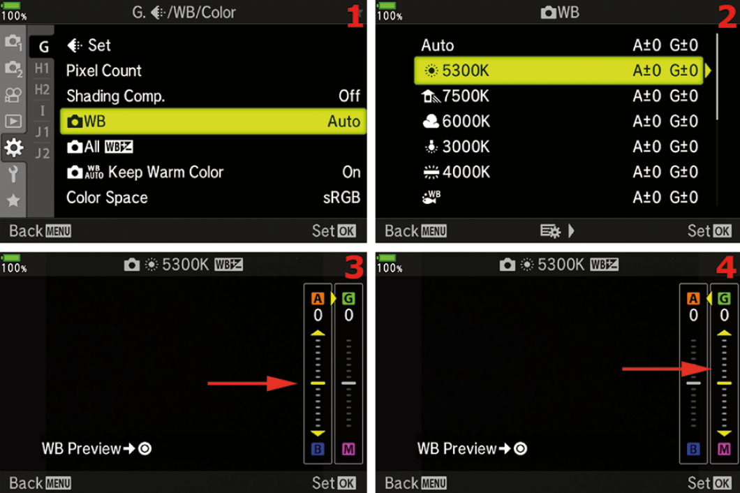
Figure 7.143: Choosing and adjusting an individual WB setting
Use the following steps to choose a WB value and modify the color of individual WB settings:
- Select the WB function from the G. [Record Mode]/WB/Color menu and scroll to the right (figure 7.143, image 1).
- Choose one of the individual WB settings, such as Auto, [Sunlight] 5300K, or [Shade] 7500K (figure 7.143, image 2). Refer to the previous list of 13 WB settings to determine what each WB setting does. If you don’t need to adjust the color balance (A–B and G–M) of an individual WB setting, simply press the OK button to select a WB setting, and skip the next three steps.
- If you want to fine-tune a certain WB setting, you can do so by highlighting it and scrolling to the right. I scrolled to the right on the [Sunlight] 5300K WB setting, which led me to the screen in figure 7.143, image 3. I can now fine-tune the color balance of the [Sunlight] setting. You can see at the point of the arrow in image 3 that there is an adjustment available. You can slide the yellow bar up toward A (amber) to increase amber for this WB setting, or you can slide it down to reduce amber (add blue). You can see a WB Preview at any time by pressing the Movie button, which causes the camera to take a temporary picture of the subject, with the fine-tuned WB value applied, and display it on the monitor. If you need to fine-tune it some more, simply move the slider again and press the Movie button again to see the results. Do this as many times as you want to fine-tune the WB setting. When you are done, either press the OK button to Set the fine-tuned amber (A–B) ratio and skip the rest of these steps, or scroll to the right to move to the green (G–M) ratio adjustment.
- After you have fine-tuned the amber (A–B) color balance, you can fine-tune the green (G–M) color balance by scrolling right and selecting the sliding adjustment shown in figure 7.143, image 4. You can add green to the WB setting by sliding the yellow bar up toward G (green), or you can scroll down to decrease green (add magenta). Press the Movie button to take a temporary picture (WB Preview), examine the color balance, and make further adjustments if necessary. When you are satisfied with the G adjustment, press the OK button to Set the value.
- Whenever you Set one of the color values in the previous steps by pressing the OK button, the camera will return to the WB function on the Custom Menu. You have modified this WB setting for all future pictures until you reset or modify it.
- Repeat these steps for any other individual WB settings you want to fine-tune.
Choosing a Custom White Balance (CWB)
If you would like to experiment with entering direct Kelvin values into the camera, or if you have specific color temperature needs, you can use the CWB setting under the WB function to choose a custom WB from 2000K to 14,000K. Let’s examine how!

Figure 7.144: Manually choose a Kelvin WB value from 2000K to 14,000K
Use the following steps to choose a specific custom WB value:
- Select the WB function from the G. [Record Mode]/WB/Color menu and scroll to the right (figure 7.144, image 1).
- Choose the CWB setting (at the end of the list of 13 WB values) and scroll to the right (figure 7.144, image 2).
- The CWB setting allows you to experiment with specific values from cool (2000K) to warm (14000K), as shown in figure 7.144, images 3 and 4. If you shoot in a studio and the light does not vary, you can manually find the best WB setting for your product images and portraits. The factory default is 5400K under CWB. Choose the best setting for your style of photography from the up/down menu.
- Press the OK button to Set the custom WB value. In the future you can choose and use this CWB setting from the WB settings in the Live Control screen or here on the WB function menu.
Settings Recommendation: White balance is an art in itself, especially for JPEG shooters. For RAW shooters, this setting does not matter because the WB of a RAW file can be changed after the fact.
You can let the camera choose the best WB by using Auto mode, which is what I often do because I shoot in RAW mode.
You must use an accurate WB if you shoot JPEGs because the WB value is a permanent part of a JPEG image. Although you can vary the color balance somewhat in a JPEG image, it never is quite right after it has been changed.
You can choose a preset WB value (e.g., Cloudy, Incandescent, Fluorescent), do a One-Touch Capture WB reading from a white or gray card, or enter a custom WB value under CWB. The E-M1III has a full range of WB controls that allow you to use whatever is most convenient.
[Camera] All WB +/− (G)
In the previous section ([Camera] WB), we discussed fine-tuning the colors of individual White Balance (WB) settings. You can change the amber–blue (A–B) ratio or the green–magenta (G–M) ratio for each WB setting individually; CWB cannot be modified.
The [Camera] All WB +/− function is for people who dislike the color balance of all WB functions. All WB +/− allows you to adjust the amber and green ratios for all WB settings at the same time (not including CWB). When you use this function to set the amber–blue (A–B) ratio and the green–magenta (G–M) ratio, it changes the color balance of every WB setting except CWB.
Let’s examine how to make a global WB compensation (fine-tuning) adjustment.
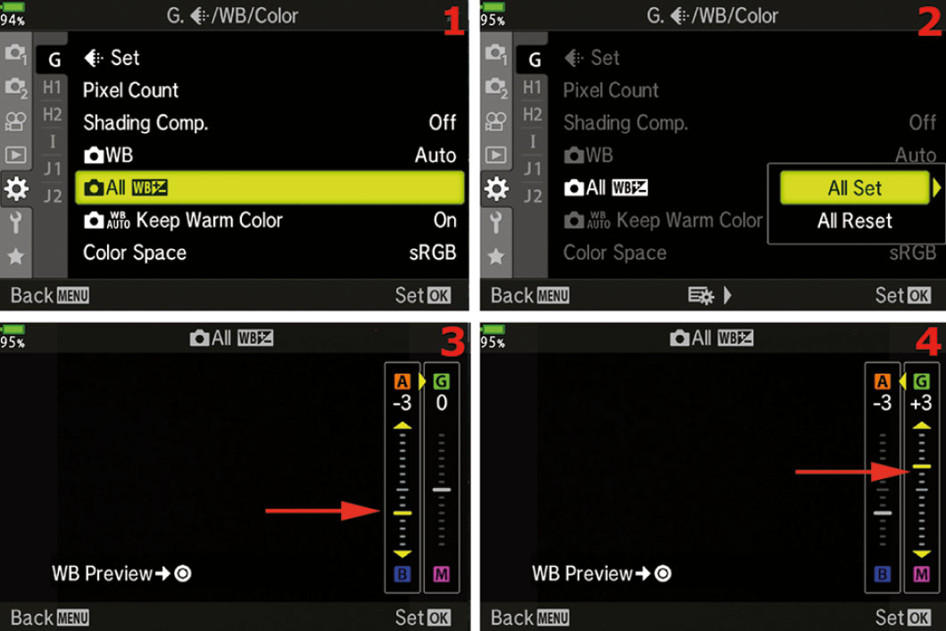
Figure 7.145: Adjusting the A and G color ratios for all WB settings at once (except CWB)
Use the following steps to modify the amber–blue ratio (A–B), and green–magenta ratio (G–M), for all WB settings at the same time (except CWB):
- Select the All WB +/− function from the G. [Record Mode]/WB/Color menu and scroll to the right (figure 7.145, image 1).
- Choose All Set from the All WB +/− menu and scroll to the right (figure 7.145, image 2).
- You can see at the point of the arrow in figure 7.145, image 3, that there is an adjustment available. You can slide the yellow bar up toward A (amber) to increase the amber color for all WB settings, or slide it down to reduce amber (add blue). You can see a WB Preview of the current WB setting that the camera is using by pressing the Movie button, which causes the camera to take a temporary picture of the subject, with the fine-tuned WB value applied, and display it on the monitor. If you need to fine-tune it some more, simply move the slider again and press the Movie button again to see the results. Do this as many times as you want to fine-tune the WB settings. When you are done, you can either press the OK button to Set the fine-tuned (A–B) ratio and skip the rest of these steps, or you can scroll to the right to move into the (G–M) ratio adjustment.
- After you have fine-tuned the amber (A–B) color balance ratio, you can fine-tune the green (G–M) color balance ratio by scrolling right and selecting the sliding adjustment shown in figure 7.145, image 4. You can add green to the WB setting by sliding the yellow bar up toward G (green), or you can slide it down to decrease green (add magenta). Press the Movie button to take a temporary picture (WB Preview), examine the color balance, and make further adjustments if necessary. When you are satisfied with the G adjustment, press the OK button to Set the value.
- When you Set one of the color values in the previous steps by pressing the OK button, the camera will return to the WB function on the Custom Menu. You have modified all WB settings, other than CWB, for all future pictures the camera will take using any WB setting, until you reset or modify them with this function.
If you make this comprehensive WB setting modification and later want to change all the WB settings back to their factory default values, you can use the upcoming steps to do so.
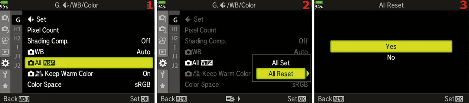
Figure 7.146: Resetting all modified WB settings
Use the following steps to reset 12 of the 13 WB settings (not CWB) back to factory specs:
- Select the All WB +/− function from the G. [Record Mode]/WB/Color menu and scroll to the right (figure 7.146, image 1).
- Choose All Reset from the All WB +/− menu and scroll to the right (figure 7.146, image 2).
- Select Yes from the All Reset menu to reset all modified WB settings, or No to cancel (figure 7.146, image 3).
- Press the OK button to Set your choice.
Settings Recommendation: I may modify one or two of the WB settings, but never all of them at the same time. However, this function is good for people who modify multiple WB settings and want to return them all to factory specs at the same time, instead of going into the menu settings for them one at a time.
WB Auto Keep Warm Color (G)
When you take pictures under incandescent light sources or warm light sources (reddish lighting), the camera will either allow the image to be a little warmer than normal (keep warm color), or it will not.
Many people love the look of warm colors. The human eye seems to be attracted to reddish colors more than bluish colors. Therefore, many people leave this setting On, which keeps the warm colors when the light source is warm. Selecting Off will cause the camera to balance the light toward neutral. The effect is noticeable.
Let’s see how to choose one of the WB Auto Keep Warm Color settings.
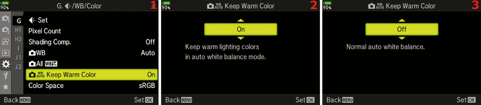
Figure 7.147: Choosing a color warmth setting
Use the following steps to choose color warmth over color neutrality when you shoot under warm light sources, such as incandescent:
- Select the WB Auto Keep Warm Color function from the G. [Record Mode]/WB/Color menu and scroll to the right (figure 7.147, image 1).
- Choose On from the WB Auto Keep Warm Color up/down menu to keep the warm colors, or choose Off to balance the light toward neutral (figure 7.147, images 2 and 3).
- Press the OK button to Set your choice.
Settings Recommendation: After testing this function under various light sources, I noticed that warm light sources have a marked effect when this function is set to On. I like warmer colors, but at times the effect seems a little strong to me, especially when I am shooting JPEGs and cannot adjust them later.
I suggest testing this function under various warm light sources to see if the image looks too warm. You may love the warmer images. More neutral images will be best for people who shoot JPEGs, where color accuracy is a must.
If you shoot in RAW mode, it makes no real difference because you can simply change the WB after the fact.
Color Space (G)
Color space is an interesting and important part of digital photography. It helps your camera fit into a much broader range of imaging devices. Software, printers, monitors, and other devices recognize which color space is attached to your image and use it, along with other color profiles, to help balance the image and produce the correct colors.
The two color spaces available on the E-M1III have different gamuts, or ranges of color. They are called sRGB and Adobe RGB. Let’s discuss color space briefly so you can make an educated choice.
Which Color Space Should I Choose?
Adobe RGB uses colors from a broad selection of the total color range that approximates human vision (called CIELAB in the graphics industry), so it has a wider gamut than sRGB (figure 7.148). If you are taking images that might be printed commercially, Adobe RGB is often the best color space to use (see the sidebar called Which Color Space Is Best, Technically?).
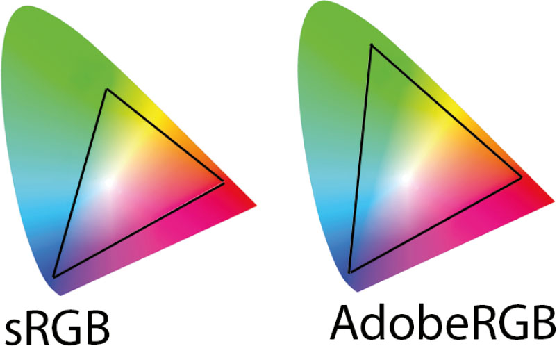
Figure 7.148: sRGB and Adobe RGB color spaces
After a JPEG file is created, either in a camera or on a computer, both the Adobe RGB and sRGB color gamuts are compressed into the same number of color levels. A JPEG has only 256 levels for each of its red, green, and blue (RGB) channels. However, since the Adobe RGB color space takes its colors from a wider spectrum, you will have a better representation of reality when there are lots of colors in your image.
If you shoot in RAW format a lot, you may want to consider using Adobe RGB to store the maximum number of colors in your image files for later use, even though, for reasons we’ll discuss in a moment, it really doesn’t matter in RAW mode. However, it is still a good idea to leave your camera set to Adobe RGB.
An E-M1III lossless compressed 12-bit RAW (ORF) image file can contain 4,096 levels of color per RGB channel, instead of the limited 256 levels in an 8-bit JPEG. Using Adobe RGB makes a lot of sense when you shoot in RAW mode because of its capacity to contain more colors as a base storage medium.
There are some drawbacks to using Adobe RGB, though. The sRGB color space is widely used in printing and display devices. Many local labs print with sRGB because so many point-and-shoot cameras use that format. If you try to print directly to some inkjet printers that are configured for sRGB using the Adobe RGB color space, the colors may not be as brilliant as with sRGB. If you aren’t going to modify your images in post-processing and plan to print them directly from your camera, you may want to use sRGB. If you shoot only JPEGs for computer display or Internet usage, it might be better to stay with sRGB for everyday shooting.
If you are a RAW shooter and regularly post-process your images, you should consider using Adobe RGB. You will have a wider gamut of colors to work with and can make your images the best they can be. Later, you can convert your images to another color space (e.g., sRGB, CMYK, CIELAB) so you can get great prints from inkjet printers and other printing devices. Here is a rough way to look at it:
- Many people who regularly shoot in JPEG format use sRGB.
- Many people who regularly shoot in RAW format use Adobe RGB.
These are not hard-and-fast rules, but many people follow them. I shoot RAW a lot, so I often use Adobe RGB.
In reality, though, it makes no difference which color space you choose when you shoot in RAW because the color space can be changed after the fact in your computer. However, many people are not in the habit of changing the color space during a RAW to JPEG conversion. Therefore, if you need the extra color range, why not leave the camera set to Adobe RGB for later convenience? Why add an extra step to your digital darkroom workflow? If you are shooting for money—such as for stock image agencies—most companies expect you to use Adobe RGB. It has a larger color range, so it’s the quality standard for most commercial printing.
Now let’s examine how to choose the color space you want to use.
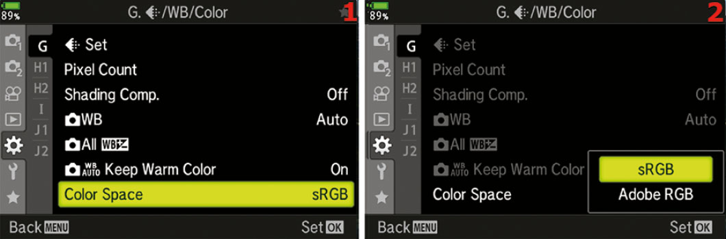
Figure 7.149: Choosing a Color Space for your images
Use the following steps to choose an appropriate Color Space for your type of photography:
- Select the Color Space function from the G. [Record Mode]/WB/Color menu and scroll to the right (figure 7.149, image 1).
- Choose one of the two Color Space settings (sRGB or Adobe RGB) from the Color Space menu after referring to the previous material in this chapter subsection (figure 7.149, image 2).
- Press the OK button to Set your choice.
Settings Recommendation: I use Adobe RGB most of the time because I shoot a lot of nature pictures with a wide range of color. I want the most accurate color my camera can give me. Adobe RGB has a wider range of colors, so it can be more accurate when my subject has a lot of colors.
However, if you are taking JPEG snapshots, there’s no need to worry about this. Leave the camera set to sRGB and have fun.
Which Color Space Is Best, Technically?
There is a large color space used by the graphics industry called CIELAB or CIE L*a*b*. The CIELAB color space is designed to approximate human vision. Adobe RGB covers about 50 percent of the CIELAB color space, and sRGB covers only about 35 percent. In other words, Adobe RGB has a wider gamut. That means Adobe RGB gives your images access to significantly more colors, especially cyans (bluish tones) and greens. Another important consideration if you’ll send your work to companies that use offset printing—such as book and magazine publishers—is that Adobe RGB maps very well to the four-color cyan, magenta, yellow, black (CMYK) printing process. If you are shooting commercial work, you may want to seriously consider Adobe RGB. Stock photo shooters are nearly always required to shoot in Adobe RGB.
Custom Menu H1–H2. Record/Erase
The H1–H2. Record/Erase menu is composed of functions that work with image file naming, photographer identity, copyright, and image deletion.
We will start examining the functions by taking a look at the opening menu for the H1–H2. Record/Erase functions in figure 7.150.

Figure 7.150: The H1 and H2 Record/Erase menu
To enter the menu, you must select H1. (or H2.) Record/Erase from the Custom Menu and scroll to the right. There are six functions inside the H1. Record/Erase menu and three functions in the H2. Record/Erase menu. Let’s consider each of them in detail.
Card Slot Settings (H1)
The E-M1III has two memory card slots (figure 7.151) and the Card Slot Settings function allows you to specify where your camera saves the images and videos you take. You can tell the camera which card to send still image files to, which card to send video files to, and how to deal with the files when a card is full.
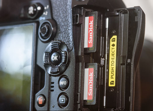
Figure 7.151: The two memory card slots on the E-M1III
Note: If there is only one memory card inserted in the camera, then the only available choice in the Card Slot Settings menu is Assign Save Folder. If there are no memory cards inserted in the camera, then the entire Card Slot Settings submenu will be grayed out.
Let’s take a look at all of the available settings.
- [Photo] Save Settings: This option allows you to choose which memory card combination the camera will use when it saves an image you just captured. The E-M1III defaults to saving all images in the top slot (Slot 1) and ignores the card in the bottom slot (Slot 2), but you can change this relationship if you wish. You have six choices:
- Standard: If there is only one memory card in the camera, the camera will save all images to that card (of course). If there are two cards in the camera, the E-M1III will save all images to whichever card slot is specified in the [Photo] Save Slot menu (below [Photo] Save Settings in the Card Slot Settings menu). When the selected memory card becomes full, you cannot save any more pictures or videos.
- Dual Same ↑: This mode lets you save the same files to both cards at the same time. Whatever Image Quality you choose is written to both cards simultaneously. If either memory card becomes full, you may continue taking pictures, as long as the other memory card has available space.
- Dual Same ↓: This mode works the same as Dual Same ↑ (previous list item) in that you can choose a certain Image Quality format for both cards to receive at the same time. However, If either memory card becomes full, you may no longer take pictures.
- Dual Independent ↑: With this setting, the two cards are treated separately, and you can select a different Image Quality format for each memory card in Shooting Menu 1. For example, you can set Slot 1 to save a RAW file and Slot 2 to save Large Fine JPEG (LF). Then when you press the Shutter button, the camera will capture and save a RAW file to the card in Slot 1, and it will also save a Large Fine (LF) JPEG file to the card in Slot 2. If either card becomes full, you may continue taking pictures, as long as there is space available on the other memory card.
- Dual Independent ↓: This mode works the same as Dual Independent ↑ (previous list item) in that you can choose a different Image Quality format for each memory card. However, if either card becomes full, you can no longer take pictures, even if there is space available on the other memory card.
- Auto Switch: This mode is very similar to Standard mode. When the card you’ve chosen for [Photo] Save Slot is full, the camera will automatically switch to the other memory card, allowing you to continue taking images until both cards are full. You may use only one Image Quality format (or one combined format, such as LF+RAW) at a time. This setting does not apply to capturing video—it applies only to still image capture. The camera will not switch to the other memory card when it runs out of space for recording video. Instead, the video will merely stop recording when the card becomes full. If you attempt to capture another video without changing to a memory card that has sufficient space, you will see an error message on the monitor telling you the card is full.
- [Photo] Save Slot: This option allows you to choose which card will record still image files. You can choose from Slot 1 or Slot 2. This option is only available when [Photo] Save Settings (the previous menu option) is set to Standard or Auto.
- [Video] Save Slot: This option allows you to choose which card will record video files.
- [Playback] Slot: When [Photo] Save Settings is set to any of the four Dual options, the camera will display the images from only one of the cards during image playback. This menu allows you to choose the card slot (1 or 2) from which you want to display images when you press the camera’s Playback button. The images will look the same regardless of which card slot you choose. The only difference is that they may be in different image formats (e.g., RAW versus JPEG). However, one of the cards may have images on it that the other does not, so you may prefer to display images from one card over the other. You can switch the Playback image display between the two cards at any time with this setting.
- Assign Save Folder: This setting allows you to choose a specific folder on the memory card in which the camera will save your images. You can choose Do Not Assign, and the camera will simply create new folders as needed, or you can choose to save images to an existing folder or a new folder that you’ve created.
Now let’s consider how to configure each of these options.
[Photo] Save Settings

Figure 7.152: The [Photo] Save Settings menu
Use the following steps to choose a recording method for still images:
- Select Card Slot Settings from the H1. Record/Erase menu and scroll to the right (figure 7.152, image 1).
- Select [Photo] Save Settings from the Card Slot Settings menu and scroll to the right (figure 7.152, image 2).
- Use the Arrow Pad to select an option from the up/down menu (figure 7.152, image 3). Refer to the previous list for an explanation of each option.
- Press the OK button to Set your choice and return to the previous screen.
Settings Recommendation: This is a very useful menu for creating an in-camera backup and for recording two different file types at the same time. When I’m photographing events, I often need to turn over the JPEG images for editing, but I want to shoot RAW images for backup. I set this to Dual Independent ↓ so that if a single card fills up, the camera lets me know that I need to put in two new cards. This is the best protection because it ensures that there is enough space for both the RAW and JPEG files.
[Photo] Save Slot
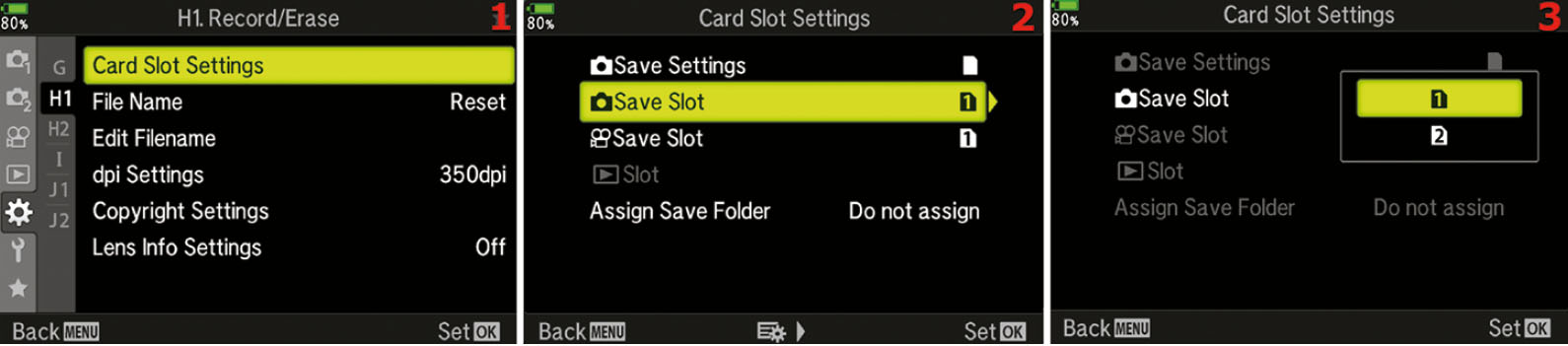
Figure 7.153: Selecting a card for still image files
This [Photo] Save Slot option is available when you set [Photo] Save Settings to either Standard or Auto Switch.
Use the following steps to choose which card will record your still image files:
- Select Card Slot Settings from the H1. Record/Erase menu and scroll to the right (figure 7.153, image 1).
- Select [Photo] Save Slot from the Card Slot Settings menu and scroll to the right (figure 7.153, image 2).
- Select card slot 1 or card slot 2 from the up/down menu (figure 7.153, image 3).
- Press the OK button to Set your choice.
Settings Recommendation: I always pick slot 1 because it supports the higher speed UHS-II type cards, whereas slot 2 supports the slower UHS-1 cards.
[Video] Save Slot
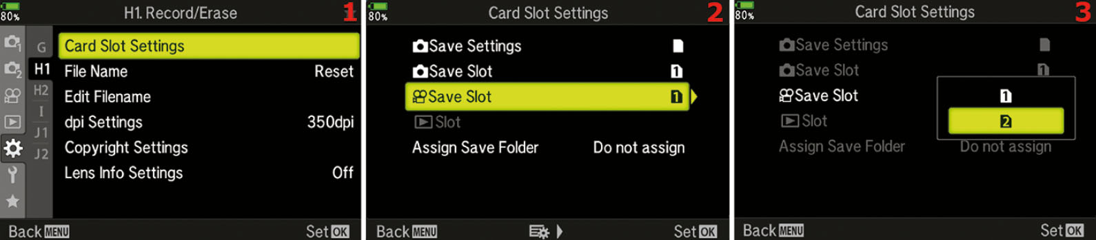
Figure 7.154: Selecting a card for video files
The [Video] Save Settings option is available regardless of how you configured [Photo] Save Settings.
Use the following steps to choose which card will record your video files:
- Select Card Slot Settings from the H1. Record/Erase menu and scroll to the right (figure 7.154, image 1).
- Select [Video] Save Slot from the Card Slot Settings menu and scroll to the right (figure 7.154, image 2).
- Select card slot 1 or card slot 2 from the up/down menu (figure 7.154, image 3).
- Press the OK button to Set your choice.
Settings Recommendation: As with the last menu, I usually pick slot 1 because it supports the higher speed UHS-II type cards, whereas slot 2 supports the slower UHS-1 cards. If I know I am going to be shooting a lot of video and a lot of still images, I will choose slot 2 for [Video] Save Slot and slot 1 for [Photo] Save Slot because it makes it easier to sort out my files later.
[Playback] Slot
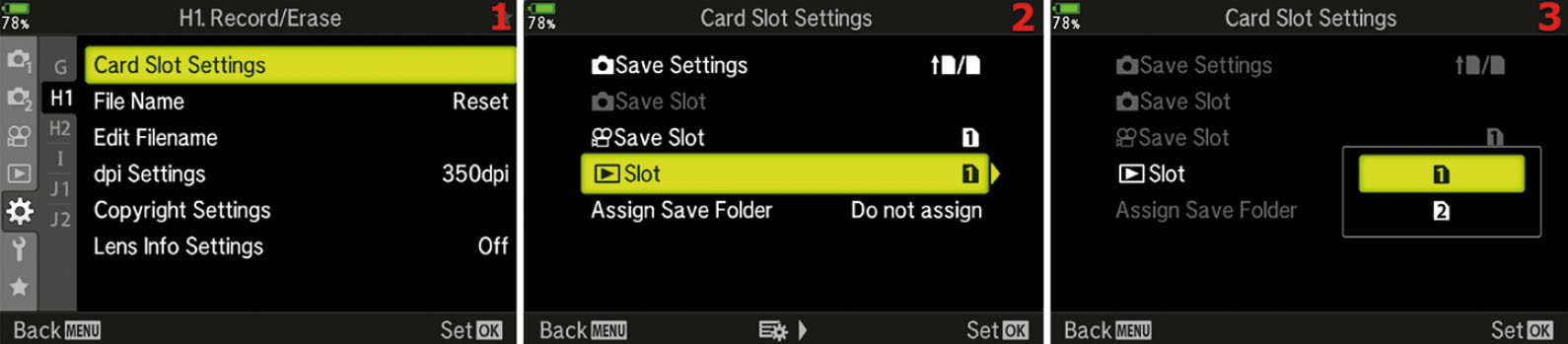
Figure 7.155: Setting the [Playback] Slot
This menu choice is available when you set [Photo] Save Settings to any of the Dual settings.
Use the following steps to choose the card from which you want to display images when you press the Playback button:
- Select Card Slot Settings from the H1. Record/Erase menu and scroll to the right (figure 7.155, image 1).
- Select [Playback] Slot from the Card Slot Settings menu and scroll to the right (figure 7.155, image 2).
- Select card slot 1 or card slot 2 from the up/down menu (figure 7.155, image 3).
- Press the OK button to Set your choice.
Settings Recommendation: I choose whichever slot contains the card with JPEG images. I just want the camera to use the JPEG file for the preview.
Assign Save Folder

Figure 7.156: Assigning your images to a specific folder on the memory card
Use the following steps to assign your images to a specific folder on the memory card:
- Select Card Slot Settings from the H1. Record/Erase menu and scroll to the right.
- Select Assign Save Folder from the Card Slot Settings menu and scroll to the right (figure 7.156, image 1).
- If you do not want to assign your images to a specific folder, and you want the camera to simply create new folders as needed, choose Do not assign and press the OK button to Set your choice (figure 7.156, image 2). If you want to assign your images to a specific new or existing folder on your memory card, choose Assign and scroll to the right (figure 7.156, image 3).
- To create a new folder on your memory card, choose New Folder and scroll to the right. Use the Arrow Pad to enter a new three-digit folder number, and then press the OK button to Set your choice (figure 7.156, image 4). Your images will be saved to the folder that you created on your memory card.
- To save your images to a folder that already exists on your memory card, choose Existing Folder and scroll to the right (figure 7.156, image 5). You will be presented with a list of folders on your memory card (figure 7.156, image 6). Choose the folder to which you want to save your images and press the OK button to Set your choice. Your images will be saved to the folder that you selected.
Settings Recommendation: I leave my camera set to Do not assign, allowing the camera to create new folders as needed.
File Name (H1)
The camera can create a running sequence of image file numbers so you can maintain a series of image numbers over time, even when a freshly formatted memory card is inserted. Alternatively, the camera can start over with a new sequence of image numbers when you insert a blank, formatted card.
Here are the two available settings and an explanation of how they work:
- Auto: The last four digits of the image file name run in a continuous series, even if you insert a blank, formatted memory card. File numbers are remembered from the previous card, and the file number on the next new image will be one higher than the previous number. In other words, if the final image on the memory card you last used had a file name ending in 0135 (e.g., P1010135.JPG), the next image you make will use 0136 (e.g., P1010136.JPG). This numbering sequence will continue until you have taken 9,999 images, then the file number sequence for the last four digits will roll back over to 0001.
- Reset: Similar to the Auto mode, the camera will use the next available image number for any series of existing pictures it finds on a memory card. However, if you insert a blank, formatted memory card into the camera, it will forget the previous memory card sequence and start fresh with folder 100 and image numbers beginning at 0001. In other words, when the camera detects a blank memory card, it resets the numbering sequence back to 0001.
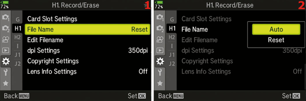
Figure 7.157: Choosing a file naming method (file number sequence)
Use the following steps to choose how you want the camera to handle file number sequences:
- Select the File Name function from the H1. Record/Erase menu and scroll to the right (figure 7.157, image 1).
- A small up/down menu will appear with two choices: Auto and Reset (figure 7.157, image 2). Make your selection (refer to the previous list for an explanation of how each selection works).
- Press the OK button to Set your choice.
Special Image Number Sequence Information
If you are interested in maintaining a continuous file number sequence for all future images with the camera using Auto, there are three important facts you should take note of. If you are using Reset instead of Auto, none of the following bulleted items matter because the camera will reset the file number sequence whenever it sees a blank memory card. If you use Auto, read these three bullets carefully:
- File folder management: The camera creates a file folder to hold your individual images when you first format or use a blank memory card. The image folder will be in the DCIM folder on the memory card and will have a name like 100OLYMP. If you exceed 9,999 images in the existing 100OLYMP folder, the camera will create a new folder with one higher number (e.g., 101OLYMP). Additionally, if you insert a memory card that has a folder containing an image with a file number ending in 9999, the camera will create a new folder in preparation for the next 9,999 images, even if there aren’t actually 9,999 images in the previous folder. Any time the camera sees the number 9999 on the end of an image, it will immediately create the next folder in the series and switch to the new folder.
- Accidentally disrupting an existing file number sequence: Since the camera remembers the last file number on the previous memory card that was inserted in the camera, if you insert a memory card with images that have a different sequence of file numbers, the camera will immediately remember the new sequence and disrupt your controlled sequence of file numbers. In other words, if the file number sequence you have been maintaining ends in 8995 and you insert a memory card with existing images that have a different number sequence (e.g., 3456), you will lose your controlled sequence. Therefore, if you want to keep a running sequence, never insert a memory card with foreign images on it. Always use an existing card in the image number series, or start with a blank, formatted card. If you accidentally insert a memory card that has a different sequence, you will need to reinsert a card that contains the old sequence and take a picture. If you cannot reinsert the old card, format a new card in the camera, copy the final image from the old sequence into the DCIM > 100OLYMP folder, then take a picture. That will reestablish the sequence.
- Using a file number sequence on a new camera: Be very careful to not insert any memory card with existing images from a different Olympus camera into a brand-new E-M1III. If you do, the camera will not start your number sequence at 0001 for the new camera. Instead, it may pick up the file number sequence from the other camera’s images. Always start your new camera’s file number sequence with a blank memory card, then follow the concepts in the previous bulleted item.
Settings Recommendation: I set my camera to Auto because I want to maintain a continuous file number sequence for my images. However, this means I have to be careful about using memory cards with foreign Olympus images on them. The next subsection discusses how to start and maintain a file number sequence properly.
Edit Filename (H1)
File naming allows you to control the first four characters of the file name for each of your images shot with the sRGB color space, and three characters of the file name for images taken with the Adobe RGB color space. You can change the characters to any alphanumeric characters available on the camera.
The camera defaults to using the following file naming convention for your images:
•sRGB color space: |
P1011234 |
•Adobe RGB color space: |
_1011234 |
For the Adobe RGB color space, the camera adds an underscore to the beginning character position, instead of the default P, which allows you to use the next three characters for custom naming. For the sRGB color space, the camera does not add an underscore, so you can use all four character positions for custom naming.
I use this feature on my camera in a special way. Since the camera can count images in a file number sequence (see the previous File Name subsection) that continues from 0001 to 9999, I use the Edit Filename function to help me personalize my images. The camera cannot count images higher than 9,999. Instead, it rolls back to 0001 for the 10,000th image.
When I first got my camera, I changed the three default characters from P101 to DRY1 for the sRGB color space and DY1 for the Adobe RGB color space. The 1 tells me how many times my camera has passed 9,999 images, and DRY or DY are my initials, which helps me protect the copyright of my images in case they are ever stolen and misused.
Since the camera’s file number sequence counter rolls back to 0001 when you exceed 9,999 images, you need a way to keep from accidentally overwriting images from the first set of 9,999 images. I use the following method:
sRGB color space
•First 9,999 images: |
DRY10001 through DRY19999 |
•Second 9,999 images: |
DRY20001 through DRY29999 |
•Third 9,999 images: |
DRY30001 through DRY39999 |
•Fourth 9,999 images: |
DRY40001 through DRY49999 |
Adobe RGB color space
•First 9,999 images: |
_DY10001 through _DY19999 |
•Second 9,999 images: |
_DY20001 through _DY29999 |
•Third 9,999 images: |
_DY30001 through _DY39999 |
•Fourth 9,999 images: |
_DY40001 through _DY49999 |
My system only works up to 89,991 images (9,999×9). If you start your camera at 0 (DRY09999 or _DY09999), you can count up to 99,990 images.
If my method doesn’t work for your needs, you can use the three or four custom characters to classify your image names in all sorts of creative ways.
Let’s see how to assign custom characters.
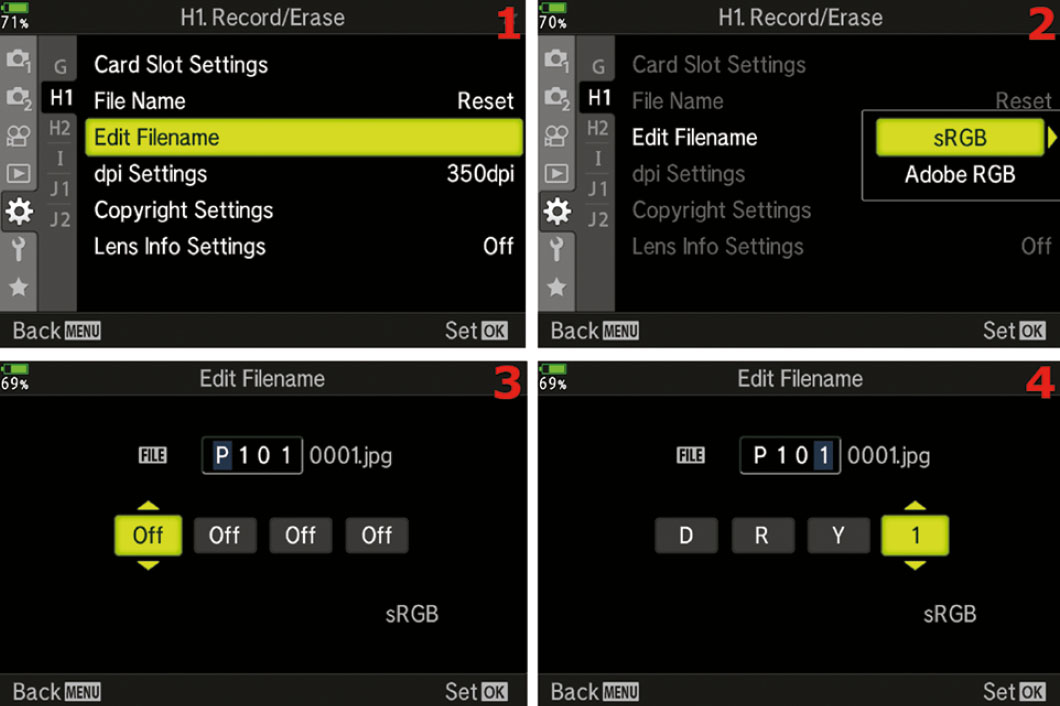
Figure 7.158: Selecting four beginning file name characters for sRGB image files
Use the following steps to choose four new initial characters for image files created with the sRGB color space:
- Select the Edit Filename function from the H1. Record/Erase menu and scroll to the right (figure 7.158, image 1).
- Choose sRGB from the up/down menu and scroll to the right (figure 7.158, image 2).
- You will see the current file name for an sRGB file, which is shown as P101 0001.jpg in figure 7.158, image 3. Choose a number or alphabetical character for each of the up/down menus that have Off displayed. Those four boxes represent the first four characters of the file name, which you can customize. Scroll up or down to select a custom character for each box. After you have chosen a value for one of the boxes, scroll right or left to select other boxes and change them too. In figure 7.158, image 4, you can see that I have added my initials (DRY) to the first three custom positions and the number 1 to the fourth custom position. Now all my sRGB images will have a file name that begins with DRY1 (e.g., DRY10123.jpg).
- Press the OK button to Set your choice.
Next, let’s consider how to change the custom characters for Adobe RGB files.
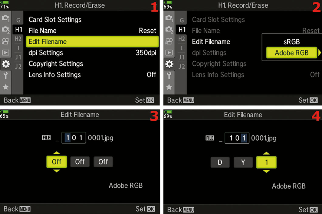
Figure 7.159: Selecting three beginning file name characters for Adobe RGB image files
Use the following steps to choose three new initial characters for image files created with the Adobe RGB color space:
- Select the Edit Filename function from the H1. Record/Erase menu and scroll to the right (figure 7.159, image 1).
- Choose Adobe RGB from the up/down menu and scroll to the right (figure 7.159, image 2).
- You will see the current file name for an Adobe RGB file, which is shown as _101 0001.jpg in figure 7.159, image 3. Choose a number or alphabetical character for each of the small up/down menus that have Off displayed. The first character is not available to customize for Adobe RGB files, unlike sRGB files. The first character will always be an underscore. The three boxes with Off displayed represent the next three characters of the file name, which you can customize. Scroll up or down to select a custom character for each box. After you have chosen a value for one of the boxes, scroll right or left to select other boxes and change them, too. In figure 7.159, image 4, you can see that the default underscore is in the first position, I added my initials (DY) to the second and third character positions, and I added the number 1 to the fourth custom position. Now all my Adobe RGB images will have file names beginning with _DY1 (e.g., _DY10123.jpg). The alignment of the three Off boxes seems to indicate that you can change the underscore, but you can’t. You can change only the second through fourth characters for the Adobe RGB color space.
- Press the OK button to Set your choice.
Note: To change between the sRGB and Adobe RGB color spaces, see the function at Custom Menu > G. [Record Mode]/WB/Color > Color Space.
Settings Recommendation: At the beginning of this section, we discussed how I use these three or four custom characters. You may want to use your initials or some other numbers or letters. Some people leave these characters at their default values. I recommend at least using your initials so you can easily identify images as yours. With my family of photographers, it sure makes it easier for me! If you use my method, be sure to watch for the images to roll over to 9999 so you can rename the numeric custom character for the next sequence of 9,999 images.
dpi Settings (H1)
With the dpi Settings function, you can select a default dpi (dots per inch) for your images. The dpi information is then embedded in the metadata of your images. This information is primarily for printers to control the dots per inch they use to make a print.
This value can be changed after the fact in computer software, such as Photoshop. You can therefore ignore this setting unless you want to print your images with a specific dpi setting. This is a useful setting for those who want to print directly from their camera or use DPOF (digital print order format) from a memory card.
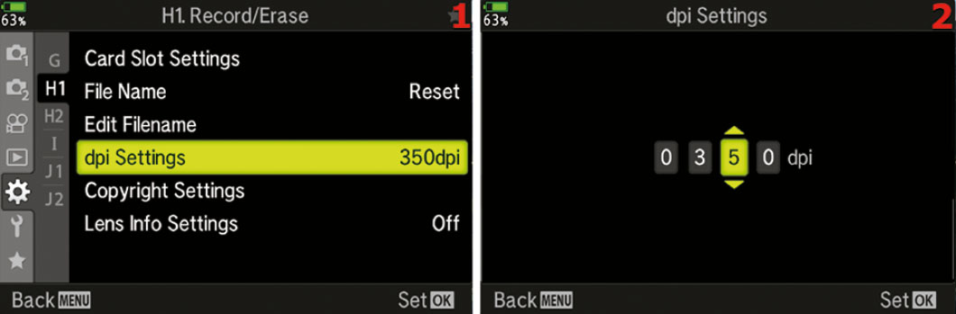
Figure 7.160: Choosing a dots per inch (dpi) setting for printing
Use the following steps to choose a default dpi value for your images:
- Select the dpi Settings function from the H1. Record/Erase menu and scroll to the right (figure 7.160, image 1).
- Select a dpi value from the up/down menus in figure 7.160, image 2. You can choose from a range of 0001 (1 dpi) to 9999 dpi. The dpi setting will affect the printing resolution of the image on an inkjet printer or other types of printers. Many printing devices have a much more limited range than 0001 to 9999 dpi. The most common dpi for commercial printing in books and magazines is 300 dpi. Since the tiny dots a printer creates to make up an image vary among printer types, you may have to experiment with different dpi settings to see which looks best on your printer.
- Press the OK button to Set your choice.
Settings Recommendation: I set my camera to 300 dpi because most of my work is printed at that dpi setting. If you rarely print your work, or if you prefer changing the dpi later in the computer, you can ignore this function. The quality (resolution) of the image will not be affected, regardless of how this setting is configured.
In my opinion, it is better to set this value in the computer just before the image is printed; therefore, I look at this function as a convenience setting.
Copyright Settings (H1)
The Copyright Settings function allows you to embed Artist Name and Copyright Name into the metadata of each image. With image theft so rampant on the Internet today, it is a good practice to put your personal or business name inside each image so it can be read on a computer. The government has recently been considering legislation for how to handle images that are orphaned. It isn’t a good idea to let your images be orphaned!
By adding your initials to the image file name with the Edit Filename function and adding artist and copyright names with this Copyright Settings function, you are invisibly marking your images internally so that, at the very least, you can prove that you own the copyright to the image. An unscrupulous person could strip out the image EXIF information; however, because your image contains the information in the first place, stripping the image is illegal and can indicate that the image was stolen. This gives you greater ammunition for proving copyright infringement. In addition to using these safeguards, you can register the copyright for your images at www.copyright.gov.
Now let’s examine how to add your personal information to your images.
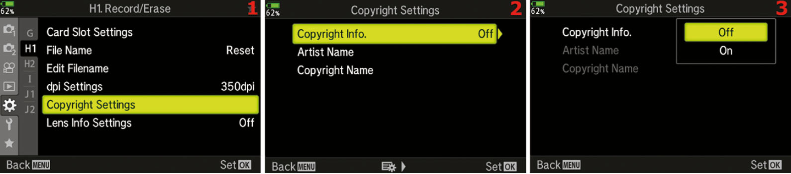
Figure 7.161: Enabling Copyright Settings
Use the following steps to enable or disable the Copyright Settings function:
- Select the Copyright Settings function from the H1. Record/Erase menu and scroll to the right (figure 7.161, image 1).
- Choose Copyright Info. and scroll to the right (figure 7.161, image 2).
- A small up/down menu will appear and offer you these choices: Off to disable the inclusion of your Artist Name and Copyright Name inside your images, or On to include that very important information (figure 7.161, image 3).
- Press the OK button to Set your choice.
Next let’s create the Artist Name and Copyright Name so it will be in the image metadata.
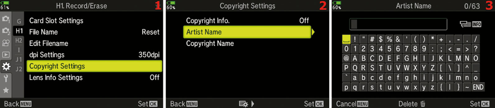
Figure 7.162: Including your Artist Name in the EXIF information of an image
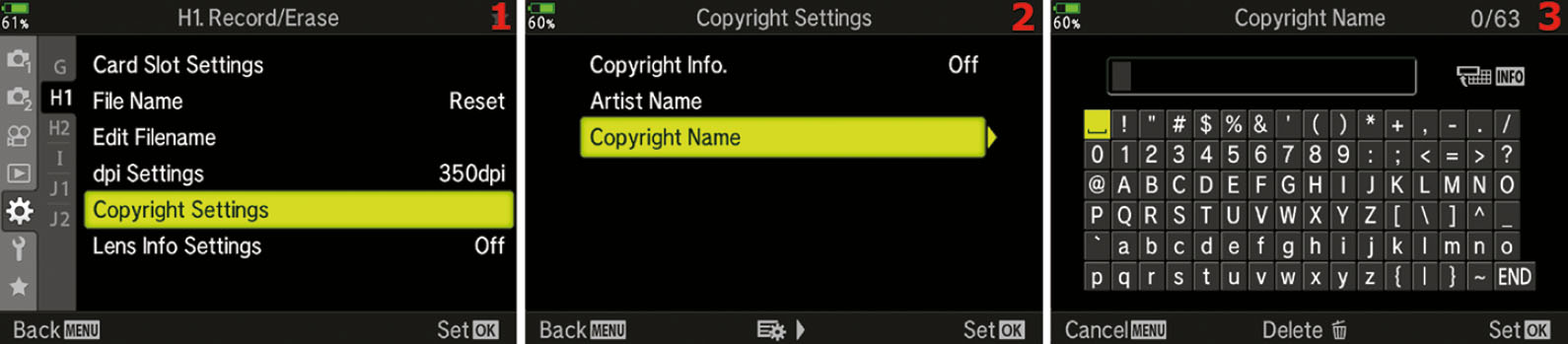
Figure 7.163: Including your Copyright Name in the EXIF information of an image
Use the following steps to add your Artist Name and Copyright Name to future images. Both names are inserted the same way, so the following steps will work for both:
- Select the Copyright Settings function from the H1. Record/Erase menu and scroll to the right (figure 7.162 or 7.163, image 1).
- Choose Artist Name or Copyright Name from the menu and scroll to the right (Figure 7.162 or 7.163, image 2).
- You will now see a screen with a grid of characters you can use for the Artist Name or Copyright Name (figure 7.162 or 7.163, image 3). There is a maximum of 63 characters available for each name. Now follow these steps to create the name:
- Inserting a character: Use the Arrow Pad to move the yellow highlight square around the gray grid of characters. When the character you want to use is under the yellow highlight, press the OK button to add the character to the line at the top of the screen. Note that there is a space character at the top-left corner of the character grid (yellow highlighted).
- Fixing a mistake: If you make a mistake, simply press the INFO button and the cursor will jump to the top where the already inserted characters are. Then you can scroll to the mistake and fix it. Position the cursor over the incorrect character and press the Delete button (red trash can). The incorrect character will disappear. Immediately press the INFO button again and the cursor will jump back to the grid of characters so you can insert the correct character. When you select the correct character, the camera will insert it automatically and move the other characters to the right.
- Saving the name: When you are done creating the Artist Name or Copyright Name, move the yellow highlight cursor down to the bottom right of the character grid to the END selection. Highlight END and press the OK button to save the name.
Settings Recommendation: One of the first settings I change on my camera is this one. I want my name and initials all over the internal metadata of my images. This is a form of protection. At the very least, the fact that you own the original image with correct metadata proves that you took the image and own the copyright. Above all else, if you are concerned about your images, especially for commercial reasons, gather up a few hundred of them, and register them at www.copyright.gov.
Lens Info Settings (H1)
You can store the lens information (name, focal length, and aperture value) for up to 10 lenses that do not automatically supply their information to the camera. Information for each lens must be entered separately. Once a lens is entered, you can edit the information or delete the lens.
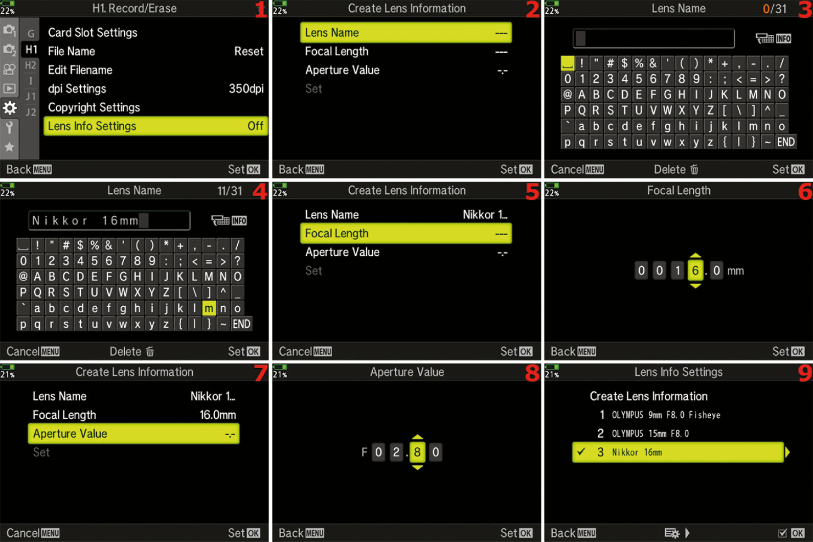
Figure 7.164: The Lens Info Settings in use
Use the following steps to add a lens to the built-in lens information database:
- 1. Select Lens Info Settings from the H1. Record/Erase menu and scroll to the right (figure 7.164, image 1).
- 2. Choose Create Lens Information from the menu and scroll to the right.
- 3. You will now see a screen with Lens Name, Focal Length, and Aperture Value (figure 7.164, image 2). Highlight Lens Name and press the right arrow to open the screen in figure 7.164, image 3.
- 4. Now follow these steps to enter the lens name:
- Inserting a character: Use the Arrow Pad to move the yellow highlight square around the gray grid of characters. When the character you want to use is under the yellow highlight, press the OK button to add the character to the line at the top of the screen, where you can see the lens name, Nikkor 16mm, in the figure. Note that there is a space character at the top-left corner of the character grid (yellow highlighted in figure 7.164, image 3).
- Fixing a mistake: If you make a mistake, simply press the INFO button and the cursor will jump to the top where the already inserted characters are. Then you can scroll to the mistake and fix it. Position the cursor over the incorrect character and press the Delete button (red trash can). The incorrect character will disappear. Immediately press the INFO button again and the cursor will jump back to the grid of characters so you can insert the correct character. When you select the correct character, the camera will insert it automatically and move the other characters to the right.
- Saving the name: When you are done creating the Lens Name, move the yellow highlight cursor down to the bottom right of the character grid to the END selection. Highlight END and press the OK button to save the name and return to the previous screen.
- 5. Now scroll down to Focal Length and press the right Arrow key (figure 7.164, image 5).
- 6. Enter the focal length of the lens using the Arrow Pad up/down keys to select the numbers and the left/right keys to move between the fields (figure 7.164, image 6). Press the OK button to Set your choice and return to the previous screen.
- 7. Scroll down to Aperture Value and press the right arrow key (figure 7.164, image 7).
- 8. Enter the aperture value using the Arrow Pad up/down keys to select the numbers and the left/right keys to move between fields (figure 7.164, image 8). Press the OK button to Set your choice.
- 9. Return to the Lens Info Settings menu, and you will see that your lens is now included in the menu (figure 7.164, image 9). You can edit or delete the lens information at any time.
Quick Erase (H2)
The Quick Erase function gives you two ways to delete an unwanted image from the memory card: with explicit permission only, and immediately upon request. To erase an image you must display it on the camera monitor and press the Erase button on the back panel of the camera (looks like a red trash can).
At the time of deletion you can have the camera ask your permission first, or you can simply delete the image as soon as you press the Erase button. If you use the latter method (immediate erase), make sure you have selected the correct image to delete because the camera will truly delete it immediately.
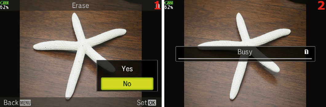
Figure 7.165: Two types of image deletion: with permission (image 1) and immediate (image 2)
Figure 7.165 shows the screens you will see depending on how you configure this function. Image 1 shows the screen that asks permission before erasing the image. Image 2 shows what happens when no permission is required; the image will be immediately deleted when you press the Erase button.
Whichever method you choose affects erasing only one image at a time, and the image to be erased must be displayed on the camera monitor. Let’s consider how to choose an erase method for unwanted images.

Figure 7.166: Choosing erase with permission only, or immediate deletion upon request
Use the following steps to choose the single-image deletion method you prefer:
- Select the Quick Erase function from the H. Record/Erase menu and scroll to the right (figure 7.166, image 1).
- From the Quick Erase menu (figure 7.166, image 2) choose Off if you want the camera to ask for your explicit permission before it deletes an image when you press the Erase button. Choose On if you want the camera to instantly delete a displayed image as soon as you press the Erase button, without confirmation. The factory default is Off.
- Press the OK button to Set your choice.
Settings Recommendation: At first I set my camera to erase an image immediately (Quick Erase set to On), then I accidentally deleted a precious image of my pregnant daughter. I had to go through the trouble of using an image recovery program to save the deleted image. This made me rethink immediate deletion. Now I use the permission required method (Quick Erase set to Off) because it displays the image with a Yes/No choice, giving me a moment longer to think before deleting an image.
If you delete a lot of images after you take them, the immediate deletion method (On) will save you considerable time. Just make sure you are deleting the correct image!
RAW+JPEG Erase (H2)
When you set the Record Mode for still pictures to JPEG+RAW, the camera creates one identical image in each format for every picture you take.
That means two images are being stored for each picture, which uses up a lot of memory card capacity. Therefore, you will probably delete more images than normal to save space.
The RAW+JPEG Erase function lets you specify how to erase single image pairs. When you press the Erase button, do you want to erase both the RAW and JPEG file, just the RAW file, or just the JPEG file? You can choose. Let’s see how!
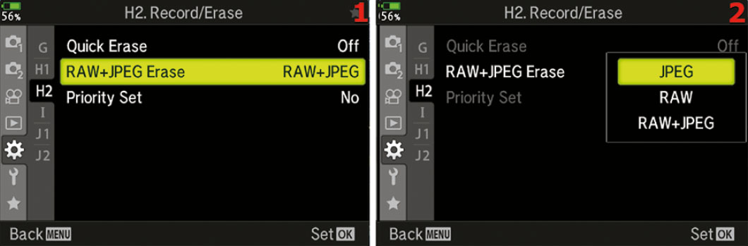
Figure 7.167: Choosing which image formats to erase with the Erase button
Use the following steps to choose how you want to erase RAW+JPEG image pairs:
- Select RAW+JPEG Erase from the H2. Record/Erase menu and scroll to the right (figure 7.167, image 1).
- From the RAW+JPEG Erase menu, choose RAW+JPEG if you want to delete both images in the set when you press the Erase button (figure 7.167, image 2). Choose RAW to delete only the RAW (ORF) file and leave the JPEG file on the memory card. Or choose JPEG to delete just the JPEG image and keep the RAW file. The factory default for this setting is RAW+JPEG.
- Press the OK button to Set your choice.
Note: This function is effective only when you are using single-frame playback, where one image at a time is displayed on the monitor or in the viewfinder. Also, if you use All Erase or Format from the Shooting Menu 1 > Card Setup function, all your images will be erased. The RAW+JPEG Erase function is for erasing a single image that is displayed on the camera monitor or in the viewfinder.
Settings Recommendation: Generally I leave this function set to the factory default of RAW+JPEG. If I want to delete an image, I normally don’t want to keep either of the formats.
However, if you are worried that the image may have some value later, or if you need to free up some memory card space while keeping at least one of the images, you can choose to delete just the RAW file or just the JPEG file when you press the Erase button.
Priority Set (H2)
When you decide to erase an image, as discussed in the previous Quick Erase function, you press the Erase button and are presented with a choice of Yes or No on a small menu.
The camera has many confirmation screens of this type, with Yes or No choices, and you can select which choice the camera defaults to when it asks for confirmation of various actions you want to perform.
Let’s see how to select a default value for Yes/No confirmation screens.
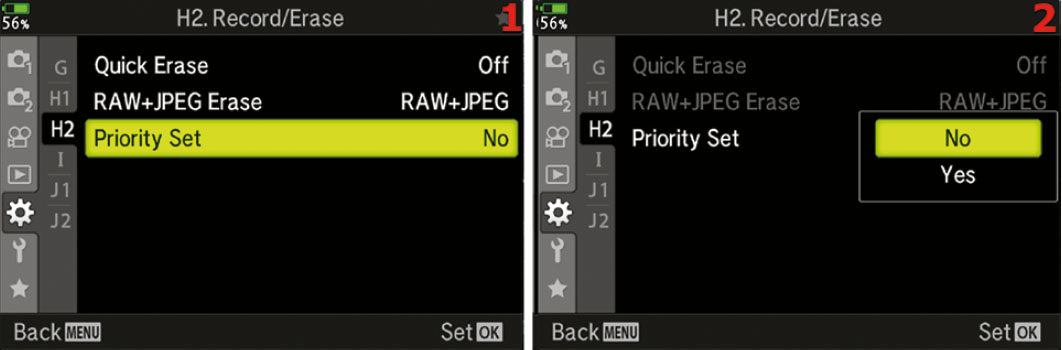
Figure 7.168: Default answer of Yes or No on confirmation screens
Use the following steps to choose a default value for when you request a change or deletion that requires a Yes or No answer:
- Select the Priority Set function from the H2. Record/Erase menu and scroll to the right (figure 7.168, image 1).
- Choose Yes if you want the camera to always have Yes selected when a Yes/No confirmation screen appears, or choose No if you prefer No to be selected. The camera defaults to No (figure 7.168, image 2).
- Press the OK button to Set your choice.
Note: The choice of Yes or No in step 2 affects many confirmation screens throughout the camera’s entire menu system. All screens with a Yes or No selection will obey the choice you make in step 2.
Settings Recommendation: I set my camera to Yes because I don’t want to make an additional choice when a Yes/No confirmation screen appears. I would rather it just default to Yes, and I can select No if I change my mind.
Custom Menu I. EVF
The I. EVF menu is primarily composed of functions that manage the electronic viewfinder (EVF) behind the eyepiece of the camera. It provides settings for things like the style of the EVF, overlays that are displayed on the EVF, how the eye sensor works, and the brightness and color balance of the EVF.
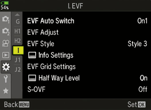
Figure 7.169: The I. EVF Menu
We will start examining the functions by taking a look at the opening menu for the I. EVF functions in figure 7.169.
To enter the menu, select I. EVF from the Custom Menu and scroll to the right. There are seven functions inside the I. EVF menu. Let’s consider each of them in detail.
EVF Auto Switch (I)
The camera has a small eye detector built in to the right side of the viewfinder, which is why the rubber viewfinder attachment has such an odd shape. If you look closely, you will see two tiny lenses at the bottom right of the viewfinder. These lenses detect when anything gets close to the viewfinder, then it closes the EVF Auto Switch and enables the internal EVF, which turns the rear monitor off.
If you prefer to use the rear monitor for all your pictures, you can disable the EVF Auto Switch. Then the camera will ignore your eye or anything else that gets close to the viewfinder and leave the rear monitor active for shooting pictures.
Let’s see how to enable or disable the EVF Auto Switch (eye sensor).

Figure 7.170: Enabling or disabling the EVF eye sensor
Use these steps to enable or disable the viewfinder eye detector:
- Select EVF Auto Switch from the I. EVF menu and scroll to the right (figure 7.170, image 1).
- Use the up/down menu to select either On1, On2, or Off for the eye sensor (figure 7.170, images 2–4). The On1 setting enables the Live View monitor until the camera senses something close to the viewfinder eyepiece, then it enables the EVF and disables the monitor. The On2 does the same thing but works with the monitor closed, The Off setting uses the Live View monitor only and turns off the eye sensor. If this function is set to Off, you can manually switch to the EVF by pressing the LV button at the left of the viewfinder, which will toggle the camera between the EVF and the rear monitor.
- Press the OK button to Set your choice.
Note: If you hold down the LV button to the left of the viewfinder eyepiece for about two seconds, the camera will open the EVF Auto Switch menu directly, and then you can select On or Off to enable or disable the eye sensor very quickly.
Settings Recommendation: I prefer to use the EVF for most of my photography. However, I do find the Live View monitor to be quite handy for casual photography and for macro shooting. Therefore, I usually leave EVF Auto Switch set to On so the camera will sense my eye approaching the viewfinder and automatically turn on the EVF and turn off the monitor.
However, I shoot macros with the Live View monitor, and I sometimes get my hand too close to the viewfinder and the monitor goes off, causing me to lose sight of my subject. When that happens, I may temporarily disable EVF Auto Switch (set it to Off) so I can keep the Live View monitor active at all times.
EVF Adjust (I)
The E-M1III automatically controls the brightness and color balance (hue) of the EVF, depending on the ambient light conditions. If you want to control the brightness and color balance of the EVF yourself, you can use this function to do so. Let’s see how.
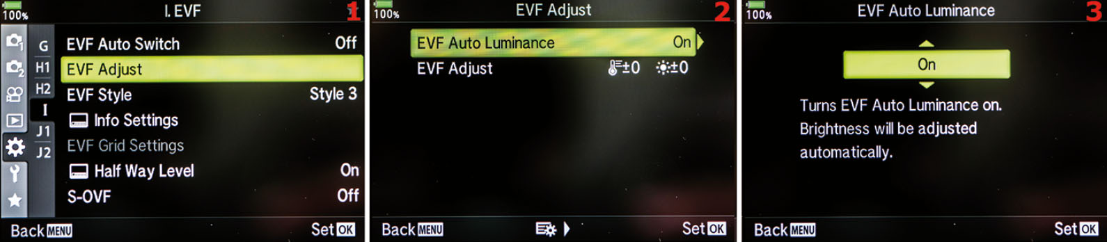
Figure 7.171: Enabling or disabling EVF Auto Luminance
Use these steps to enable or disable EVF Auto Luminance:
- Select EVF Adjust from the I. EVF menu and scroll to the right (figure 7.171, image 1).
- Choose EVF Auto Luminance from the EVF Adjust screen and scroll to the right (figure 7.171, image 2).
- Use the up/down menu to select either On or Off (figure 7.171, images 3 and 4). If you select On (default), the camera will adjust the EVF brightness and hue automatically. If you choose Off, you can use the EVF Adjust setting (second menu item in image 2) to control the EVF brightness and hue manually.
- Press the OK button to Set your choice.
Next let’s see how to adjust the EVF brightness and hue manually instead of letting the camera control it automatically.

Figure 7.172: Setting the EVF brightness and color balance
Use these steps to manually control the brightness and hue of the EVF screen. While you make these adjustments, remember that they apply to the EVF, not the Live View monitor. To make the adjustments shown in figure 7.172, images 3 and 4, you must be looking into the viewfinder to see the screens:
- Select EVF Adjust from the I. EVF menu and scroll to the right (figure 7.172, image 1).
- Choose EVF Adjust from the EVF Adjust screen and scroll to the right (figure 7.172, image 2).
- You will now see a screen in the EVF that displays the last picture you took or the last picture you viewed from the memory card. The picture is overlaid with two adjustment sliders on the right: one for brightness and one for hue or color temperature. The adjustment for brightness is on the far right side of the EVF screen (figure 7.172, image 3). You can use the keys of the Arrow Pad to scroll up or down to adjust the brightness of the EVF over a range of 15 levels. You can move the yellow bar at the point of the red arrow up seven levels (+7) or down seven levels (−7), which brightens or darkens the backlight of the EVF screen.
- When you are done, scroll to the left with the left key of the Arrow Pad to adjust the hue (color temperature) of the EVF (figure 7.172, image 4). Notice at the point of the arrow that the hue setting is 0. You can adjust the hue up seven levels (+7) or down seven levels (−7). An upward adjustment makes the hue shift toward blue (cooler), and a downward adjustment makes the hue shift toward red (warmer). Adjust the EVF color temperature until it seems right to you.
- Press the OK button to Set your EVF brightness and hue choices.
Note: The EVF brightness and hue settings are for comfort only and do not affect the brightness or hue of the images you create. The brightness and color temperature of your pictures are controlled by the exposure and white balance settings.
Settings Recommendation: I normally leave EVF Auto Luminance set to On. This lets the camera control the brightness and hue of the monitor, similar to how my iPhone adjusts when the ambient light changes. I have found the camera’s choices to be satisfactory, and the automatic control is quite convenient.
However, if you are shooting in a controlled studio environment with careful color matching, you may want to adjust the EVF until it looks best for your light source.
EVF Style (I)
The camera offers three EVF Styles, as shown in Figure 7.173. Style 1 and Style 2 have a retro film camera look. Style 3 is the factory default, which looks more modern. Style 3 imitates the layout of the rear monitor, so many people prefer this one.
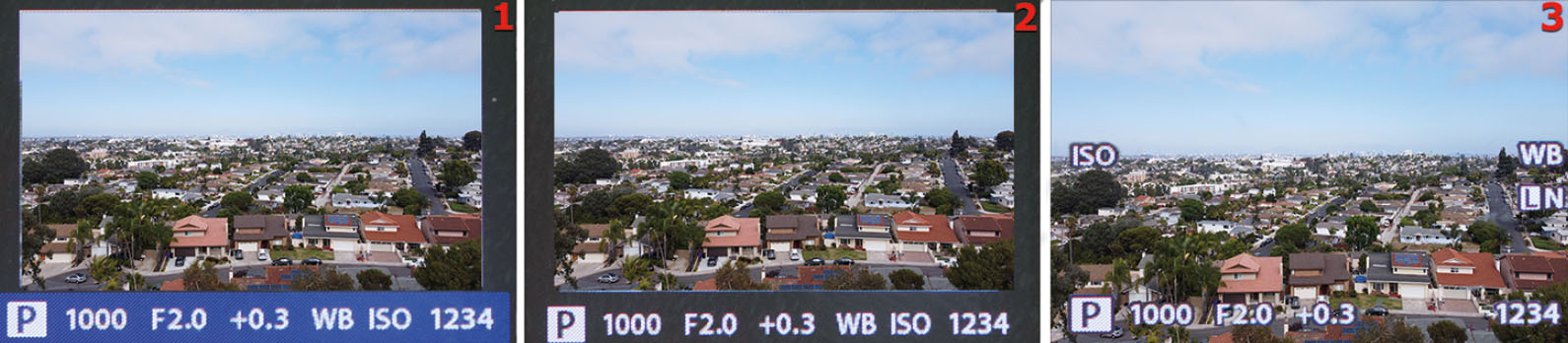
Figure 7.173: EVF Styles 1, 2, and 3
Styles 1 and 2 provide shooting information in a band at the bottom of the EVF. Style 1 has a blue band with yellow and white characters. Style 2 has a dark gray (almost black) band with yellow and white characters. Style 3 is the default. It has bright white characters with exposure information in yellow. Notice in figure 7.173 that Style 3 provides a little more magnification of the subject, making it somewhat easier to see.
Let’s examine how to select one of the EVF Styles.
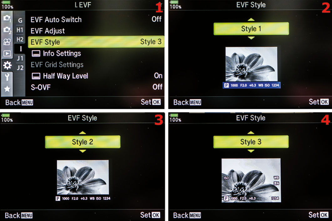
Figure 7.174: Choosing an EVF Style
Use these steps to select one of the EVF Styles:
- Select EVF Style from the I. EVF menu and scroll to the right (figure 7.174, image 1).
- Use the up/down menu to select one of the three Styles (figure 7.174, image 2–4). Refer to figure 7.173 to choose your favorite.
- Press the OK button to Set your choice.
Settings Recommendation: I generally leave my camera set to the factory default of Style 3. I like the larger view of the subject in the viewfinder and having the monitor and viewfinder look the same. However, before you make a final decision about which EVF Style you will use, examine the rest of the functions in the I. EVF menu. Some of the upcoming functions work differently when you use Styles 1 and 2.
[EVF] Info Settings (I)
Depending on which Style you chose for the EVF Style, you can have the EVF display things that are traditionally seen only on the rear monitor. The EVF can display a Live Histogram, show a Highlight&Shadow screen, present a Level Gauge, or allow a sparse Basic Information screen.
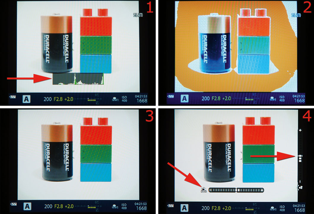
Figure 7.175: The four [EVF] Info Settings types: Live Histogram (image 1), Highlight&Shadow (image 2), Basic Information (image 3), and Level Gauge (image 4)
While choosing [EVF] Info Settings, remember that the Info overlays apply to the EVF, not the Live View monitor. To see all the selected [EVF] Info Settings, you must look into the viewfinder while pressing the INFO button repeatedly.
Let’s examine what each of the three EVF Styles display, using the screen overlays in figure 7.175, images 1–4, as examples:
- Style 1: This Style offers a blue band at the bottom with exposure information displayed similarly to a retro film camera. You can select several overlays by pressing the INFO button repeatedly. The camera offers Live Histogram (image 1), Highlight&Shadow (over-exposed areas turn orange; image 2), Basic Information (image 3), and Level Gauge (image 4).
- Style 2: This Style is virtually identical to Style 1, except it uses a black band at the bottom of the EVF instead of a blue band. See Style 1 in the previous bullet for details about the displays.
- Style 3: This Style makes the EVF perform like a smaller version of the monitor on the back of the camera. The EVF and monitor will generally look identical. Style 3 offers all the features of Styles 1 and 2 with the exception of the Highlight&Shadow (orange over-exposure) mode in figure 7.175, image 2.
Now let’s examine how to select which Info Settings you want to use in the EVF.

Figure 7.176: Choosing an [EVF] Info Settings type
Use these steps to select the Info Settings you want to use on the EVF:
- Select [EVF] Info Settings from the I. EVF menu and scroll to the right (figure 7.176, image 1).
- There are three options on the Info Settings screen: Basic Information, Custom 1, and Custom 2 (figure 7.176, image 2). When you highlight Custom 1 or Custom 2 and scroll to the right, you can access the following settings: [Live Histogram], Highlight&Shadow, and Level Gauge (figure 7.176, image 3). Remember that if you are using Style 3, Highlight&Shadow is of no use. However, if you are using either Style 1 or Style 2, you may want to check the Highlight&Shadow setting so it will show blown-out (overexposed) areas in the EVF. To check or uncheck an item, highlight it and press the OK button. When an item is checked, each Info Setting will appear on the EVF when you press the Info button repeatedly.
- Press the Menu button to return to the main menu when you are done.
Settings Recommendation: I check all the available [EVF] Info Settings in case I decide to use an EVF Style that works with that setting. I don’t see a problem with checking all of them, so why not?
EVF Grid Settings (I)
The camera can display a series of six grid types, in two custom colors, as overlays in the EVF, as seen in figure 7.177.
The six grid types will help you align your image correctly for various types of photography. The grid overlays are available only when you use EVF Styles 1 or 2 (not Style 3). If this menu choice is grayed out, it means that you have selected EVF Style 3, or that Custom Menu > D3. Disp/[Sound]/PC > Grid Settings > Apply Settings to EVF is turned on (which means that that monitor grid settings have been applied to the EVF).

Figure 7.177: The default EVF screen and six grid types
When you choose a grid type, remember that the grids apply to the EVF, not the Live View monitor. To see the grid, you must be looking into the viewfinder.
Let’s examine how to select a grid color and type for EVF Styles 1 and 2.
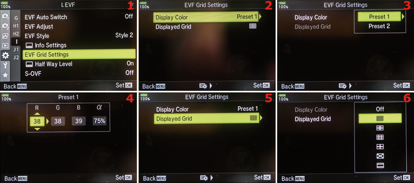
Figure 7.178: Choosing a Display Color and Displayed Grid type for EVF Styles 1 and 2 (only)
Use these steps to select a Display Color and Displayed Grid type when you are using EVF Styles 1 and 2:
- Select EVF Grid Settings from the I. EVF menu and scroll to the right (figure 7.178, image 1).
- Select Display Color and scroll to the right (figure 7.178, image 2).
- Select Preset 1 and scroll to the right (figure 7.178, image 3).
- A screen will open with value boxes for the R (red), G (green), and B (blue) color channels, as well as a box for α (alpha), which allows you to set the opacity of the grid lines (figure 7.178, image 4). Use the Arrow pad to adjust the R, G, B, and α values (if wanted), and then press the OK button to Set the values and return to the previous menu. (Repeat this process for Preset 2, if you would like.)
- Scroll down to Displayed Grid and scroll to the right (figure 7.178, image 5).
- Select one of the six grid patterns, or Off, and then press the OK button to Set your choice (figure 7.178, image 6).
Settings Recommendation: I selected the first Displayed Grid type (directly under Off). I like this grid because it helps me align the horizon when I am shooting landscapes, and it also makes it easier to shoot buildings when I’m walking around town photographing architecture. There is a grid type to suit most photo needs, so experiment with each of them to see which you prefer, if any. Using a color for the grid that is easy to see can really help, so I set the Display Color to something that will stand out in light and dark shooting scenarios, like a solid red (R 100, G 0, B 0, and Alpha 100%).
[EVF] Half Way Level (I)
If you are using EVF Styles 1 and 2, the camera displays a small Half Way Level at the bottom of the EVF. The Half Way Level is not available with EVF Style 3.
The level is called a Half Way Level because it activates when you press the Shutter button halfway down. When the level appears, it replaces the –/+ exposure indicator at the bottom of the EVF screen.
When the camera is off level horizontally, a series of white bars will extend to the left or right of the center of the scale in the opposite direction of the camera body rotation. If you rotate the camera more than a few degrees horizontally, the scale will run out of white bars, and an orange arrow will appear above the scale to indicate the camera cannot register any more degrees of rotation.
When the camera is exactly level horizontally, the center bar and the two up/down arrows above the center bar will turn green.
Let’s examine how to enable or disable the Half Way Level.
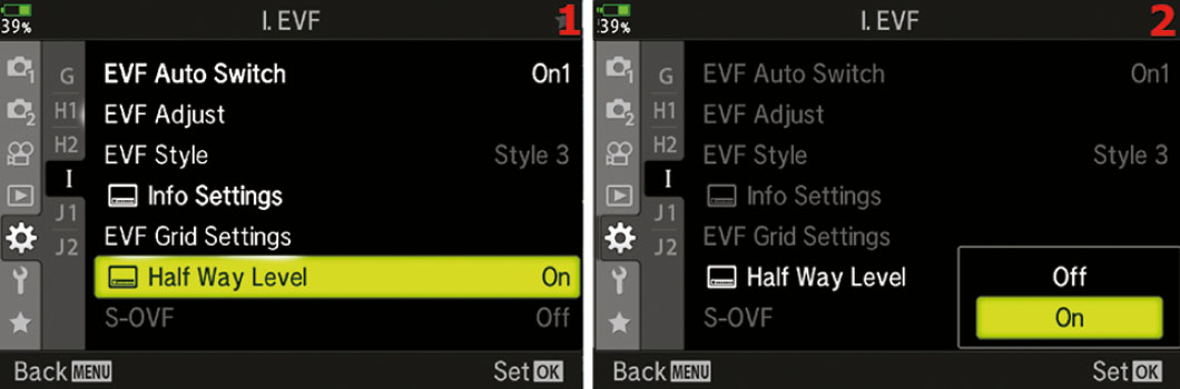
Figure 7.179: Enabling or disabling the Half Way Level
Use these steps to enable or disable the Half Way Level:
- Select [EVF] Half Way Level from the I. EVF menu and scroll to the right (figure 7.179, image 1).
- Use the menu to select On or Off to enable or disable the Half Way Level (figure 7.179, image 2).
- Press the OK button to Set your choice.
Settings Recommendation: I leave this level enabled in case I decide to use a different EVF Style than my normal Style 3. However, if I want to use a real level, I simply use the camera’s main Virtual level. It is available when you press the INFO button until the level appears on the monitor or in the EVF. The Virtual level shows left and right rotation along with forward and backward rotation.
S-OVF (I)
This setting allows the EVF to act like a traditional optical viewfinder. If this setting is turned On, the EVF will not show the effects of the current camera settings on the subject. If turned Off, the camera allows you to see the effects of your exposure choices through the viewfinder before you actually take the photo.
This is a simple on/off menu choice, but the effects it can have as you are trying to properly capture an image are huge. Seeing the effects of your exposure choices in real time allows for better decision making, so most will leave this set to Off.
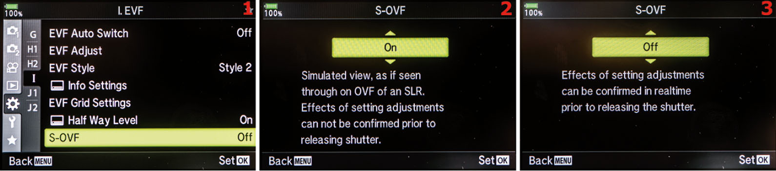
Figure 7.180: Enabling or disabling the S-OVF
Use these steps to enable or disable the S-OVF:
- Select S-OVF from the I. EVF menu and scroll to the right (figure 7.180, image 1).
- Select On to make the EVF function like a traditional optical viewfinder, or Off to see the effects of the current camera settings on the scene (figure 7.180, images 2 and 3).
- Press the OK button to Set your choice.

Figure 7.181: Simulated difference when using S-OVF turned on or off
Figure 7.181, image 1, shows a scene as it would appear through the viewfinder with S-OVF turned on (the viewfinder does not reflect the effects of the current exposure settings). Images 2 and 3 show what you would see through the viewfinder with S-OVF turned off, and with exposure settings that overexpose (image 2) and underexpose (image 3) the scene by a full stop.
Settings Recommendation: The benefit of an EVF is that it provides instant feedback on your exposure settings. However, if you’re used to an optical viewfinder, this may take some getting used to. It’s nice to have the option to make the EVF function like an optical viewfinder if you find that you prefer it. Try it out both ways and see what you like best.
Custom Menu J1–J2. [Photo] Utility
The J1–J2. Utility menu is composed of 12 functions that don’t readily fit into one of the other Custom Menus. We will start examining the functions by taking a look at the opening menu for the J1–J2. Utility menu in figure 7.182. This is the last menu system in the group of Custom Menus.

Figure 7.182: The J1–J2. Utility menu
To enter the menu, select J1. (or J2.) Utility from the Custom Menu and scroll to the right. There are five functions inside the J1. Utility menu and six functions in J2. Utility. Let’s consider each of them in detail.
Pixel Mapping (J1)
The E-M1III allows you to run a self-check on the camera sensor and image processing functions. When your camera was first manufactured, one of the final steps before the camera was released was the Pixel Mapping process. Why?
All digital cameras suffer from two maladies, both initially and over time:
- Dead pixels: A dead pixel is a photosite on the sensor that has become unresponsive. It will appear as a tiny black spot in the same place on every image unless it is mapped out.
- Stuck pixels: A stuck pixel is a photosite that reports full exposure regardless of the actual exposure. This means the pixel will always appear as one color, usually red or white, at the same place in every image. It should be mapped out.
Because the E-M1III is an advanced camera, you can run a similar Pixel Mapping function as the one used by Olympus technicians. You don’t want black, white, or colored spots in all your images, so you should run the Pixel Mapping function as needed to remap the dead and stuck pixels on your camera sensor.
Olympus recommends that you run the Pixel Mapping function at least once a year. However, if you detect dead or stuck pixels in your images when they are viewed at 100 percent on your computer monitor, you can run the Pixel Mapping function and map the bad photosites out of future images. The camera will interpolate data from surrounding pixels to fill in what should be captured at the mapped-out pixel, preventing image degradation that would otherwise be caused by using the Pixel Mapping function.
Mapping the bad pixels takes about 20 seconds, and you will hear the camera make some odd clicking noises as it tests and maps the entire sensor and image processing system.
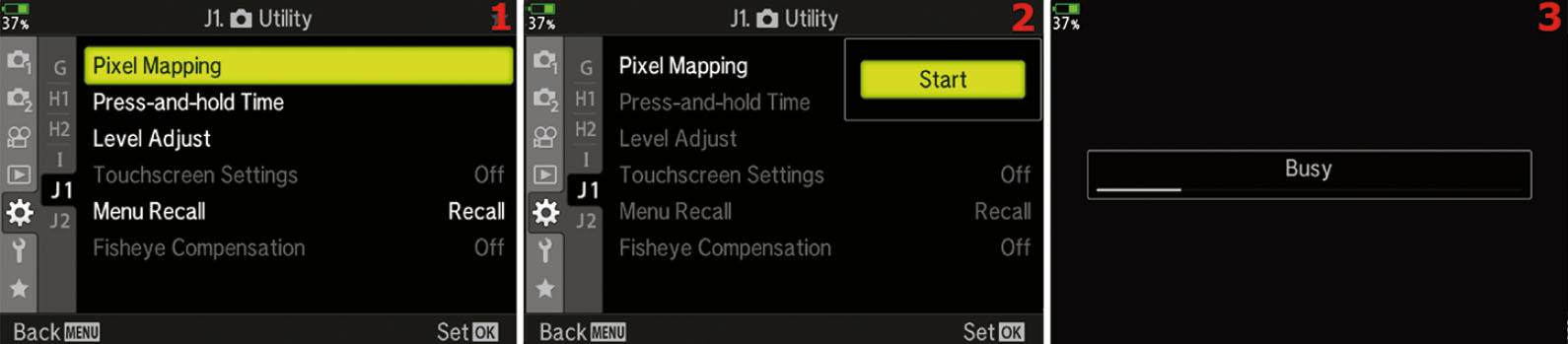
Figure 7.183: Remapping the sensor pixels
Use these steps to run the Pixel Mapping function to tune up your sensor and image processing system:
- Select Pixel Mapping from the J1. Utility menu and scroll to the right (figure 7.183, image 1).
- Choose Start from the menu and press the OK button to begin mapping the pixels (figure 7.183, image 2).
- During the Pixel Mapping process, you will hear various clicks from the camera over a period of about 20 seconds. While the camera is working you will see a Busy indicator on the screen (figure 7.183, image 3). When Pixel Mapping is complete, the camera will return to the main menu.
Note: In addition to dead and stuck pixels, you may have heard of hot pixels. A hot pixel is not a dead or stuck pixel, and the Pixel Mapping function is not designed to deal with them specifically. Hot pixels are photosites on the sensor that have become overheated due to long exposures. They will appear in images as various incorrect colors. As the camera cools, the hot pixels will cool off and return to normal. Use the Custom Menu > E1. Exp/ISO/BULB/[Meter] > Noise Reduct. function to deal with hot pixels. The camera should not map out hot pixels because they move around on the sensor.
It is not a good idea to run the Pixel Mapping function after you take a lot of exposures or a long exposure, especially when you are shooting in a warm environment. You don’t want the camera to map out pixels that are useful in normal exposures. Therefore, it is best to run Pixel Mapping before you start shooting images for the day. At the very minimum, allow the camera to cool down for at least one minute after you take pictures, and significantly longer if the camera is warm to the touch.
Settings Recommendation: This is a powerful and useful function for photographers who cannot afford to have spots on their pictures. I do not indiscriminately run this function. I run it at least once per year, or more often if I see dead or stuck pixels. All digital cameras will lose a few pixels over time, although not enough to affect the image, even after many years of use. However, aren’t you glad that Olympus gave you a Pixel Mapping function so you can take care of the problem yourself instead of having to send your camera in for service?
Press-and-hold Time (J1)
The E-M1III has 16 functions for which you must press and hold a button for a certain length of time before the camera actually responds. The Press-and-hold Time function allows you to set a specific hold time for each button. The default hold time for all buttons is 0.7 seconds, but you can change it to as quick as 0.5 seconds all the way to 3 seconds.
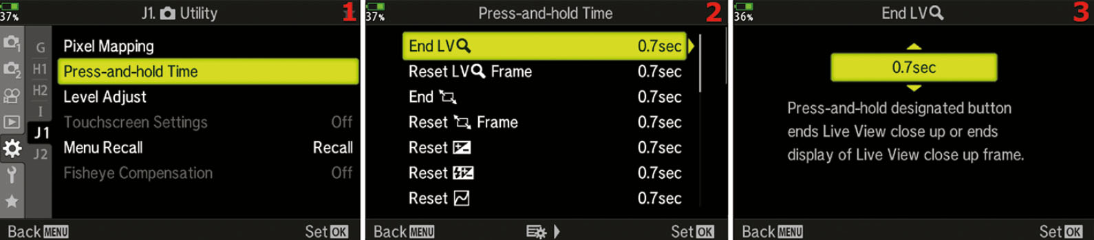
Figure 7.184: Here is the Press-and-hold time menu
Use these steps to change the Press-and-hold Time:
- Select Press-and-hold Time from the J1. Utility menu and scroll to the right (figure 7.184, image 1).
- Scroll through the list of buttons until you find the one you want to change, and then scroll to the right (figure 7.184, image 2).
- Use the Arrow Pad keys to adjust the time to 0.05–3 seconds (figure 7.184, image 3).
- Press the OK Button to Set the time and return to the list of buttons.
Settings Recommendation: I am not sure why you would want to change these times and slow the camera down. I leave all buttons set to the default 0.07 seconds, which seems to work just great.
Level Adjust (J1)
Normally, the camera’s leveling system tells you when your E-M1III is level for roll and pitch. However, if you need the camera to indicate that it is level at an unusual angle, you can adjust the level indicator.
Maybe you are shooting an unusual, off-level still life and you want the camera to line up with the still life’s angles instead of really being level. You can set the camera’s leveling system to match your special camera-angle requirements.
Let’s see how to make the camera report that it is level when it really isn’t—and yet it matches your special angle needs.
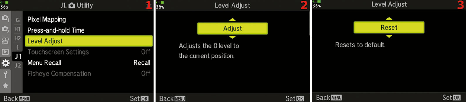
Figure 7.185: Adjusting the leveling system to give a false level reading for special uses
Use these steps to adjust the angle the camera uses to indicate that it is level:
- Select Level Adjust from the J1. Utility menu and scroll to the right (figure 7.185, image 1).
- Position the camera so it is at the exact angle you want it to consider level, then select Adjust from the up/down menu and press the OK button (figure 7.185, image 2). The camera will consider the new angle to be level. The level indicators will zero out and turn green when you place the camera at the new false-level angle.
- When you are done shooting at the false-level setting, reset the camera so it will use the true level again. Select Reset from the up/down menu and press the OK button (figure 7.185, image 3).
Settings Recommendation: This is certainly an unusual setting. I have found no use for it yet since I shoot a lot of nature images. However, I can imagine that some photographers will use this feature for specialized angle shooting, especially in the studio and maybe for some types of architectural photography. If you have a need for this setting, I’m sure you will immediately recognize it.
Touch Screen Settings (J1)
The E-M1III has a great touch screen built in to the Live View monitor on the back of the camera. You can activate various functions by simply tapping an icon or button on the screen.
However, you may not like using the touch screen and would rather just use the menu system to control the camera features. Or maybe you accidentally keep touching the screen and things happen that you did not intend. In that case you can disable the touch screen. Let’s see how.
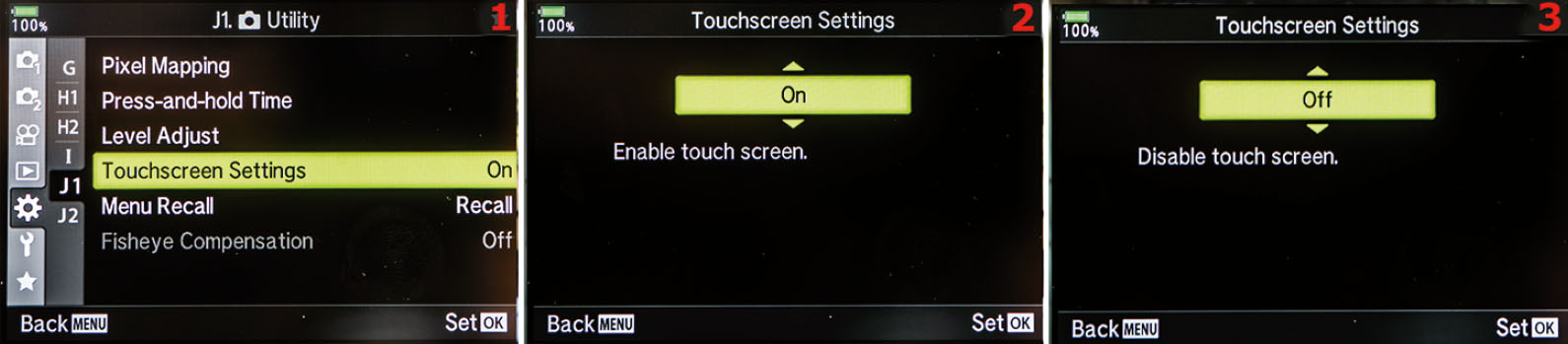
Figure 7.186: Enabling or disabling the touch screen capability
Use these steps to enable or disable the touch screen capability:
- Select Touch Screen Settings from the J1. Utility menu and scroll to the right (figure 7.186, image 1).
- Use the up/down menu to select On to enable the Touch Screen, or select Off to disable it (figure 7.186, images 2 and 3).
- Press the OK button to Set your choice.
Settings Recommendation: I leave the touch screen enabled on my camera. When I first used a camera with touch screen capabilities, I was not all that interested in using it, but then I started discovering various functions that are easier to manipulate by simply touching the screen instead of scrolling through menus. I suggest leaving the touch screen active on your camera unless you are having trouble with touching it at the wrong time.
Menu Recall (J1)
This function controls where your cursor appears when you press the Menu button. You can choose Recall or Reset. Recall will display the cursor at the last position of operation when you press the Menu button. The cursor will stay in the last position of operation even if you turn the camera off. Reset will cause the cursor to be displayed back at the beginning of the menu each time you press the Menu button. Given that the E-M1III has a very complicated menu system, it’s helpful to have this function set to Recall.
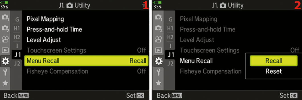
Figure 7.187: Enabling or disabling the Menu Recall feature
Use these steps to enable or disable the Menu Recall feature:
- Select Menu Recall from the J1. Utility menu and scroll to the right (figure 7.187, image 1).
- Use the up/down menu to select Recall or Reset (figure 7.187, image 2).
- Press the OK button to Set your choice.
Settings Recommendation: I leave this set to Recall so that when I press the Menu button I go back to the previous menu and not back to the beginning each time.
Fisheye Compensation (J1)
Fisheye Compensation allows you to use the M.Zuiko Digital ED 8mm F1.8 Fisheye PRO as a wide-angle lens without the fisheye effect. This menu allows you to not only fix the look of the fisheye lens, it also allows you to fix the look of the lens if used underwater.
- Select Fisheye Compensation from the J1. Utility menu and scroll to the right.
- Select On from the menu and scroll to the right. Now you will be able to adjust the Angle and the Underwater Correction.
- Press the OK button to Set your choice.
Fisheye Compensation can be applied to JPEG images; however, RAW files will retain the original fisheye effect.
Settings Recommendation: I do not have this lens, so I have not been able to test this out. It is only active when the M.Zuiko Digital ED 8mm F1.8 Fisheye PRO is attached.
Battery Settings (J2)
When you are using the optional Olympus Power Battery Holder on your E-M1III, the camera has two batteries at its disposal: the PBH battery and the Body Battery. This Battery Settings function gives you a choice of which battery to use first, and it shows you the stats of each battery.
Most people choose to have the camera use the battery inside the PBH first so the camera can continue to operate on the Body Battery if the PBH is removed. If the Body Battery is used before the battery in the PBH and you remove the PBH, the camera will not operate due to the lack of power.
Use these steps to set which battery is used first when the optional PBH is attached and a battery is inserted:
- Select Battery Settings from the J2. Utility menu and scroll to the right (figure 7.188, image 1).
- Select Battery Priority and scroll to the right (figure 7.190, image 2).
- Use the up/down menu to select either PBH Battery or Body Battery (figure 7.188, images 3 and 4).
- Press the OK button to Set your choice.
- You can also see the status of each battery by selecting Battery Status from the Battery Settings menu and scrolling to the right (figure 7.188, images 5 and 6).
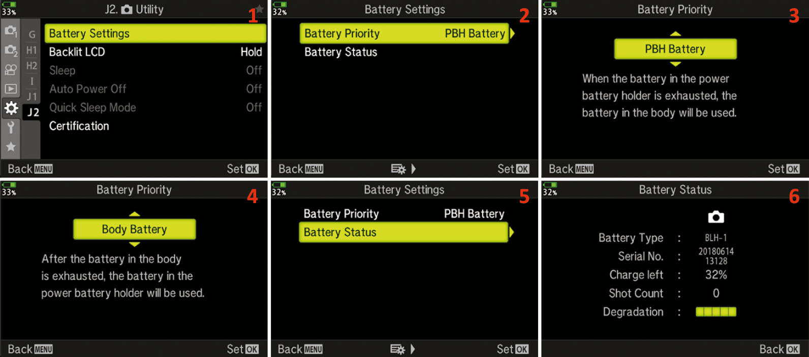
Figure 7.188: The Battery Settings Menu
Settings Recommendation: I always have this set to use the battery in the optional grip (PBH) before the battery in the camera, as it is a lot easier to change the battery in the grip than it is to change the battery in the camera with the grip attached.
Backlit LCD (J2)
The LCD monitor on the rear of the camera uses a lot of battery power. In fact, powering this monitor drains more energy from the battery than any other part of the camera. The Backlit LCD function allows you to set a time limit for the LCD monitor to stay at full brightness. When the time-out expires, the monitor will dim significantly and reduce the power drain. It does not go off completely—it just gets very dim. You can choose from 8 seconds (8sec), 30 seconds (30sec), 1 minute (1min), and Hold. The Hold setting effectively cancels the dimming process and retains the brightness all the time.
This function affects only the shooting mode when the subject is displayed on the monitor and the camera is ready to take a picture. If you venture into the camera menus with the Menu button or start viewing images with the Playback button, the time-out period does not apply. Also, the time-out period does not affect the electronic viewfinder (EVF) display, only the rear LCD monitor.
The camera also has a function called Sleep, which we will consider in the next subsection. The Sleep function completely turns off the camera monitor after one minute. If you have the Backlit LCD time-out set to 1min and Sleep set to 1min, you will not see the backlit display dim. Instead, the Sleep function will override the Backlit LCD function and turn off the monitor.
While the monitor is dimmed, you can return it to full brightness by slightly pressing the Shutter button. In fact, using any camera control will do the same. Let’s see how to choose a time-out period for dimming the Backlit LCD monitor.
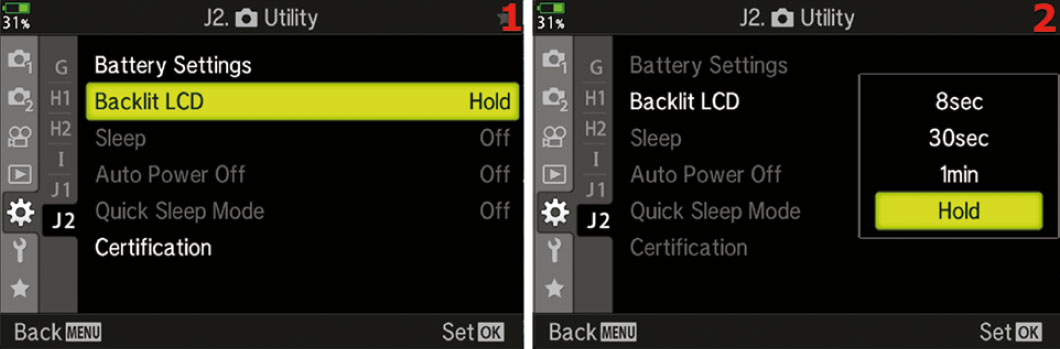
Figure 7.189: Choosing a Backlit LCD time-out period for dimming the monitor
Use the following steps to modify the Backlit LCD function:
- Select Backlit LCD from the J2. Utility menu and scroll to the right (figure 7.189, image 1).
- Select 8sec, 30sec, 1min, or Hold from the up/down menu (figure 7.189, image 2). The factory default is Hold, which never dims the screen.
- Press the OK button to Set the value.
Settings Recommendation: I set my camera’s Backlit LCD time-out to 8sec so I can save battery life. It is hard to make it through a full day of shooting with the EVF and monitor drawing so much power, so I am glad to have a dim function. I can undim the LCD by merely pressing the Shutter button halfway. If 8 seconds (8sec) is not enough time for you to compose and shoot with the LCD monitor, try 30sec or 1min. If you choose 1min, be aware that the Sleep function (next subsection) will likely prevent the monitor from dimming.
Sleep (J2)
The Sleep function could just as easily be called energy-saving mode. It puts the camera to sleep after a time-out period. Backlit LCD, discussed in the previous subsection, causes the monitor to dim significantly after a set period. The Sleep function takes it a step further by turning the monitor and electronic viewfinder (EVF) off until you use a camera control.
You can choose to have the display screens go to sleep after 1, 3, or 5 minutes (1min, 3min, or 5min), or you can turn the Sleep function off all together (Off). After the camera has gone to sleep, it will not wake back up until you press a button or turn a dial. When you do press a button—while the camera is in energy-saving Sleep mode—the camera ignores the normal function of that button and simply wakes up.
If you accidentally forget to turn the camera off and leave it in Sleep mode, it will turn itself off after a set period of time, which you can control with the Auto Power Off function (discussed in the next subsection).
Let’s consider how to choose a Sleep mode time-out.
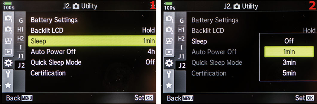
Figure 7.190: Choosing a Sleep time delay
Use the following steps to modify the Sleep function:
- Select Sleep from the J2. Utility menu and scroll to the right (figure 7.190, image 1).
- Select 1min, 3min, or 5min from the up/down menu (figure 7.190, image 2). You can also choose Off to disable the Sleep function. The factory default is 1min.
- Press the OK button to Set the value.
Settings Recommendation: I leave my camera set to 1min. The battery draw is so high for the bright screens that I want my camera to go to sleep quickly when I’m not using it.
I have found that the camera will go to sleep even when I am carrying it on a strap around my neck. At first I thought the sensor on the viewfinder eyepiece, which tells the camera to switch to the EVF, might sense my clothing and not let the camera go to sleep, but that’s not the case. If you do not use a physical camera control within the time-out period you chose in the Sleep function, the camera will shut down the display screens and go into energy-saving mode.
When the camera is in Sleep mode, it starts the countdown to Auto Power Off, which will shut down the camera completely. We will consider Auto Power Off next.
Auto Power Off (J2)
Auto Power Off shuts down your camera if you do not use it for a certain period of time. You can set the camera to automatically shut off after 5 minutes (5min), 30 minutes (30min), 1 hour (1h), or 4 hours (4h). You can also choose to disable this function so that the camera never turns off automatically.
The camera shuts down after the time-out period you select, even though the On/Off switch is set to On. If the camera has shut down with the On/Off switch set to On, you can to turn the switch Off and back On again to power up the camera. It will not come back on when you use any other camera control, unlike the Backlit LCD and Sleep functions.
Let’s examine how to choose an Auto Power Off time-out period.
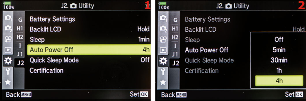
Figure 7.191: Choosing an Auto Power Off time delay
Use the following steps to modify the Auto Power Off function:
- Select Auto Power Off from the J2. Utility menu and scroll to the right (figure 7.191, image 1).
- Select Off, 5min, 30min, 1h, or 4h from the up/down menu (figure 7.191, image 2). The factory default is 4h.
- Press the OK button to Set the value.
Settings Recommendation: The 1h setting seems about right to me. If I haven’t used my camera in an hour, I probably won’t use it for a while, and I can easily switch it off and back on when I need to take more pictures. The 4h setting will work, too; however, that seems like a long time to have the camera partially active. Even though the display screens are asleep while the camera is in energy-saving mode—if the Sleep function is configured correctly—the other parts of the camera are still using more power than when the camera is off.
Quick Sleep Mode (J2)
The Quick Sleep Mode conserves power by powering down the monitor when it is not in use. When this is set to On, the camera will go into a power-saving mode during shooting when the monitor is closed or when the camera is not in Live View mode. You can continue taking pictures with the monitor off.

Figure 7.192: Setting the Quick Sleep Mode
Use the following steps to turn Quick Sleep Mode on or off:
- Select Quick Sleep Mode from the J2. Utility menu and scroll to the right (figure 7.192, image 1).
- Select On or Off from the up/down menu (figure 7.192, image 2).
- Press the OK button to Set the value.
Settings Recommendation: I keep this turned on because it can really save some power. I can continue shooting pictures without having to worry about running out of power.
Certification (J2)
This is the last option in the J2. Utility menu. While it is selectable, there is nothing here for you to do. This is where Olympus puts the CAN ICES-3(B)/NMB-3(B) information (figure 7.193).
Figure 7.193: Certification
Author’s Conclusions
Have you ever seen so many functions in one camera? I have never seen a camera with so many configuration possibilities. The advantage is that all these functions let you make your camera do almost any type of photography you can think of. And all this power is packed into such a diminutive camera.
The next chapter, Setup Menu, will cover the final functions in the camera—the initial setup functions you will probably configure only a few times while you own the camera.