Blend shape deformers, like joints, are typically associated with character animation—most often for creating facial expressions. In this chapter we'll look at some situations in which blend shapes can be a useful tool for creating other types of animated effects.
Chapter Contents
Blend Shapes and Lattices
Blend Shape In-Betweens
Interactive Blend Shape Rigs
Layering Blend Shapes
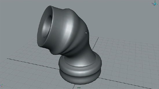
It's no secret why people such as yourself get into 3D modeling and animation—it's all about arts and crafts! In this next shot we'll be creating some CG pottery for another kids cartoon. (You'll have even more fun if you pretend that it is zombie pottery.) In this animation, the pottery spins on a wheel. After a couple seconds, something goes horribly wrong. Such is the case when dealing with zombie pottery.
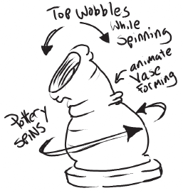
To create the pottery we'll revolve a surface using a profile curve.
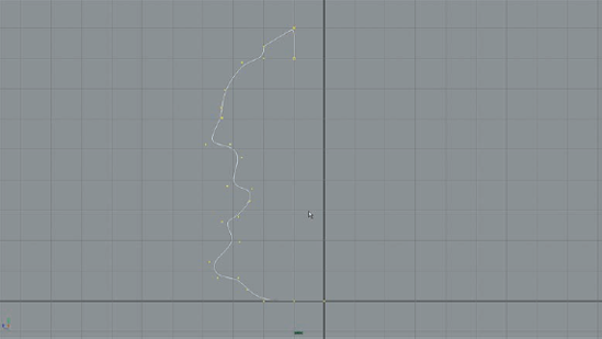
Open up a new file in Maya and switch your perspective window to a side view.
Choose a CV curve and make sure it is set to cubic under the CV Curve Settings in the options.
Draw a profile for a vase a few units from the origin. Make it fairly dense and make sure the last two points at the bottom are at the origin, as in Figure 4.1.
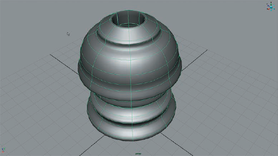
Switch to the Surfaces menu set and choose Surfaces > Revolve > Options. Reset the options and use the default settings. A pretty little vase should appear.
Assign a Blinn shader to the vase so that we get some nice highlights in the perspective window (Figure 4.2).
We want to be able to control the shape of the vase as it spins on the wheel to simulate the effect of fingers shaping it. As long as history is maintained for the surface, any changes we make to the profile curve will be reflected in the revolved surface. We want to be able to edit the curve away from the surface just so that it's easier to see what's going on. If we move the curve away from the origin, the vase will enlarge with it. However, we can move the vase geometry anywhere we want without affecting its shape. We could also create a blend shape for the curve and move that away from both the original profile curve and the vase geometry. Let's try that method.
Select the original profile curve and make a standard duplicate by choosing Edit > Duplicate. Rename the new curve "control" and the original curve "vaseProfile."
Move the control curve about 15 units in Z.
Select the control curve and then Ctrl+select the vaseProfile curve. From the Animation menu set, choose Deform > Create Blend Shape > Options.
In the options, select the Local button and the box next to Check Topology; leave In-Between unselected.
Remember that the first objects you select will be the blend shape deformers and the last object will be the object they deform. This is important to keep in mind, especially when you Shift+select multiple objects.
We can create an extra view that focuses on the control curve by making an orthographic camera.
Create a new Camera, and rename it "controlCam."
Look through the camera and position it so that the control curve is framed in view.
Open up the Attribute Editor for the controlCam. Under the Orthographic Views section, check the box next to Orthographic. The camera is now an orthographic camera like the side, front, and top cameras.
Parent the controlCam to the controlCurve, and in the perspective view, move the curve farther away from the vase.
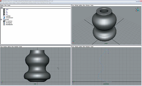
Set the panel layout to four windows. From the perspective view window, choose Panels > Saved Layouts > Four View.
Set the upper-left view to be the Outliner, the upper right to Perspective, the lower left to Side, and the lower right to controlCam (it will be listed in the view window under Orthographic Views). Use Figure 4.3 as a guide.
We'll be using the blend shape applied to the curve as an animation control. We'll apply cluster deformers to the control vertices of the blend shape curve so that we have an easy way to animate the shape of the curve.
In the controlCam view, right-click over the curve and choose Control Vertex form the marking menu.
Select each CV and create a cluster by switching to the Animation menu set and choosing Deform > Create Cluster.
In the Outliner, Shift+select all the clusters and group them. Name the group "controlClusters."
In the Outliner, select the vaseProfile curve. In its Channel Box, select blend-Shape1 under the Inputs section. Set the Control attribute to 1. This makes the control curve's blend shape strength 100%.
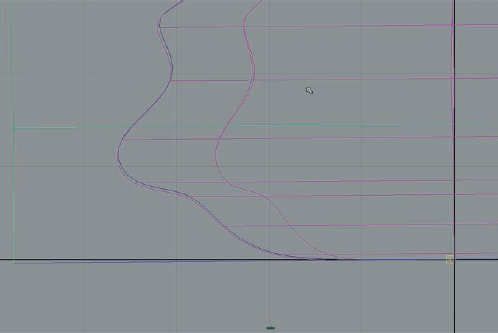
Move some of the clusters around in the controlCam view. You should see the shape of the vase update. We now have a handy control mechanism and view for our vase (Figure 4.4).
Rather than spin the actual vase object we'll apply a lattice and spin the lattice; this will allow for some flexibility in animating the vase later on down the road.
Select the vase geometry and choose, from the Animation menu set, Deform > Create Lattice. In the Channel Box, set the ffd1LatticeShape's S, T, and U Divisions to 2, 8, 2.
In the Outliner, Shift+select both the ffd1Lattice and the ffd1Base.
Switch to the Move tool and hit the Insert key on your keyboard to activate editing of the pivot point.
Move the pivot point to the base of the lattice, and grid-snap it to the origin.
Hit the Insert key again once the pivot point has been positioned.
With both the lattice and base selected, switch to the Scale tool and scale both the lattice and the base up a unit or so larger than the vase.
In the ffd1 tab of the Attribute Editor, switch the Outside Lattice option to All.
Select the lattice and switch to the Move tool. Hit the Insert key to activate the pivot editing mode. Move the pivot just slightly to the left.
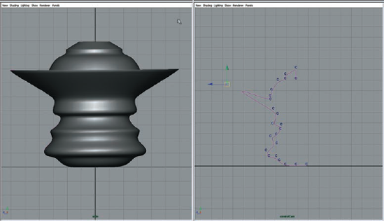
In the Channel Box for the lattice, set the RotateX to .5. This will give it a slight wobble when it spins (Figure 4.5).
Set the Timeline to 300 frames.
On the first frame of the Timeline, set a key for the Y rotation at 0.
Move to frame 10 and set the Y rotation to 720. Set another keyframe.
Open the Attribute Editor for the lattice. Under the ffd1Lattice Transform Attributes, right-click on the Y rotation channel that's highlighted in orange. Choose ffdlLattice_rotateY.output.
In the Attribute Editor for the ffdLattice_rotateY, set Post Infinity to Linear. Set InTan Type and OutTan Type to Linear as well.
In the Outliner, select the vaseProfile curve and hide it.
Play the animation and check out the crazy arts and crafts action.
We can now use the clusters on the control curve to animate the vase as if it were being shaped by invisible fingers.
Set the Timeline to frame 1. Shift+select all the clusters and use the Shift+W hot key combination to set a keyframe on the translate attributes.
Move to different frames on the Timeline, and in the controlCam view, move around the individual control clusters. Set keyframes on their positions. Have fun with setting the keyframes so that the vase looks like it's being shaped over time.
Blend shapes can be applied to lattices just like they can be applied to geometry; we'll take advantage of this to enhance the animation further.
Rewind to the beginning of the animation.
Select the lattice and duplicate it.
In the Outliner, select the new ffd1Lattice1 and ffd1Base1 objects and move them away from the base. Move them so that you can see them in the control-Cam view.
Select the new ffd1Lattice1 and Ctrl+select the original ffd1Lattice. Choose Deform > Create Blend Shape.
Set the blendShape2 input in the Channel Box for the ffd1Lattice. Set the ffd1Lattice1 attribute to 1 just as we did for the curve blend shape.
We'll add joints to the second lattice to make it easier to deform. You should be getting a sense of how you can layer deformers on top of each other to achieve a high level of control over the deformation of your objects
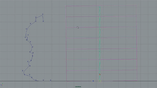
In the controlCam view, start from the bottom of the duplicate lattice and create a joint chain going up the center. You may want to use grid snapping to keep the joints in a straight line (Figure 4.6).
When the joint chain is complete, select the root joint and the duplicated lattice and choose Skin > Bind Skin > Rigid Bind.
Set the Timeline to 160, select the joints, and set a keyframe on their rotation channels.
Move the Timeline to a later frame in the animation. Select the joints parented to joint 2 and start rotating them in X and Z. Set some keyframes and have some fun experimenting with different rotations.

Note
When layering deformers such as blend shapes, lattice, or joints on a single object, the order in which you apply the deformers will affect how they deform the object. Sometimes if you get unexpected results when you animate the attributes of a deformer it may be a result of the order in which the deformers are applied. You can change the order by opening up the list of inputs for the object. To do this, right-click over the object in a viewport and from the marking menu choose Inputs > All Inputs. In the List of Input Operations dialog box you'll see all of the deformers applied to the object. To change the order, MMB click on the name of a deformer and drag it up or down in the list.
Clearly pottery is probably not the most exciting thing you'll be animating in your career; however, these principles, simple as they are, can be used for a variety of other techniques.
Try this tutorial with a denser lattice. Turn the duplicate lattice into a softbody and apply a turbulence field to the particles to see what happens. Set it up so that the goal weights at the base of the lattice have a higher value than those at the top.
Apply some gravity to the softbody particles and see if you can get the spinning vase to melt over time.
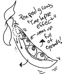
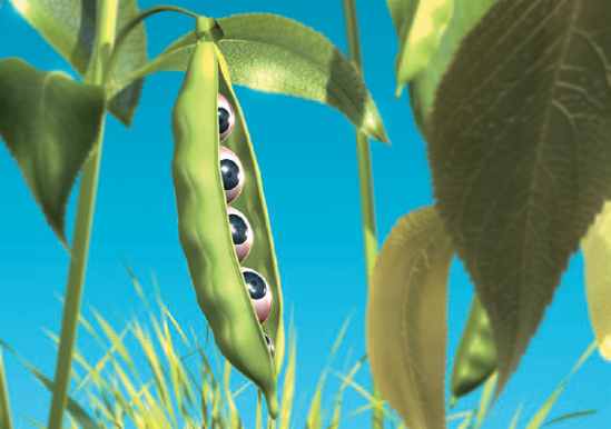
The next shot is a TV network promo for a popular cable channel. The shot calls for a time-lapse-styled animation of a peapod growing. The pod splits open and inside we see a bunch of eyeballs. Ewww gross! The art director wants to know how hard it would be to do this.
Actually it's pretty straightforward and lots of fun. To create this we'll use blend shapes, joints, and a lattice. Blend shapes have two modes: regular blend shape deform-ers, which are additive, and blend shape in-betweens. The regular additive type are used most frequently for things like facial animation. When you select a number of blend shape targets and then apply them to your model, each blend shape control is independent of the other shapes. When you set two or more blend shapes at full strength, the deformation is added together. So a smile and an open mouth shape result in an open mouth smile.
The in-between blend shape deformer type allows you to select a number of targets and apply them to your model, and the resulting blend shape is a sequence of shapes based on the order in which you select the targets. So instead of getting a smile combined with an open mouth when you animate the value of the blend shape deformer, the result would be a smile and then an open mouth in sequence. How is this useful? We'll see.
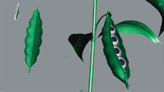
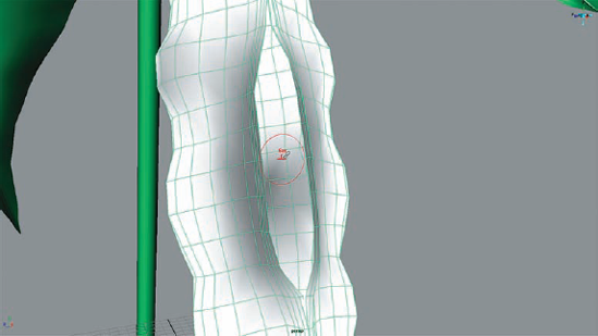
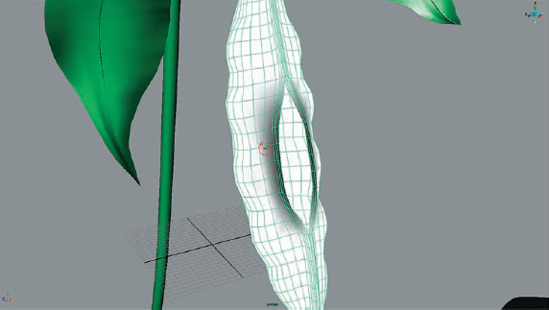
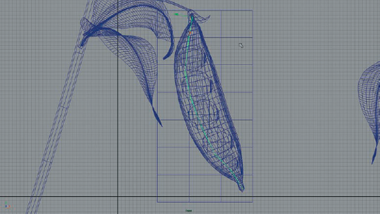
Open the peaPod_v01.mb scene from the Chapter 4 folder on the CD. You'll see that the modeler has provided us with a peapod full of eyes (modeled in the open position), the peapod in the closed position, and a small peapod at the start of its growth cycle (see Figure 4.8). There are also some leaves and a stem.
Look through camera1 to see how the shot will be framed.
Return to the perspective window. Let's test out how the blend shapes will work before we set up the rig.
Turn off the visibility for the Peas display layer to hide the eyes for the moment.
In the Outliner, select the pod_closed object, Ctrl+select the pod_start object, and then Ctrl+select the pod_end object. The order of selection is important.
From the Animation menu set choose Deform > Create Blend Shape > Options. In the options, set Origin to Local and check the In-Between box. Click Create to make the blend shape.
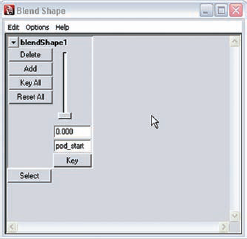
Select the pod_end object. In the Channel Box under the inputs for the shape node, select blendShape1. You'll see pod_start listed (see Figure 4.9); this is the blend shape control. It actually contains the sequence from pod_start through pod_closed and then ends with pod_end where the pod is open. To test it, choose Window > Animation Editors > Blend Shape. As you move the slider up you'll see the peapod first close and then shrink in sequence. For the final animation, we'll just reverse the keyframes for the sequence.
This animation is OK but it might look a lot better if we could have the opening split in the middle first and then spread to the ends, just to add some drama. To do this we'll create an intermediate blend shape target between the open and closed shapes by painting blend shape weights.
In the Blend Shape animation control panel, set the slider to 0.5.
Choose Deform > Paint Blend Shape Weights Tool > Options. The Artisan interface will open up in the Tool Settings palette. The peapod will turn white, indicating that the value of the pod_start blend shape target for all the vertices of the model is set to 1.
Set Paint Operation to Replace and the Value to .5.
Start painting around the center of the split in the peapod, The vertices will jump to an open position (0.5 = halfway between the pod_closed and pod_end states) and the surface around these vertices will turn gray (Figure 4.10).
You may want to move the view inside the peapod to access some of the inner vertices. It takes a little bit of work.
When the opening looks similar to Figure 4.10, switch the paint operation to Smooth and paint around the vertices that have moved to smooth out the shape.
When it looks nice and smooth, set Operation to Replace and Value to 1 and paint any of the vertices on the back of the peapod you may have accidentally painted on the back and sides.
If you want to refine the opening, you can try lowering the value of the brush, painting the opening some more, and then smoothing it out until you're satisfied. The closer to zero the value, the larger the opening will be.
When you are done painting and the opening looks similar to Figure 4.11, select the peapod_end object and duplicate it.
Move the duplicate out of the way and rename it pod_split.
Select the pod_end object and move the Blend Shape slider all the way to zero so it is back to its original, undeformed, open state.
Select all four pod objects (pod_closed, pod_start, pod_end, and pod_split) and delete history on them. This will remove the blend shape deformer on the pod end so that we can use it as a new target in the next blend shape sequence we will build in the following section.
Now that we have all the blend shape targets we need, we'll create a new blend shape sequence that includes the pod_split object.
Ctrl+select the pod_split, pod_closed, pod_start, and pod_end objects in that order.
Choose Deform > Create Blend Shape to make the blend shape sequence.
Choose Window > Animation Editors > Blend Shape to open the Blend Shape Control window.
Move the slider to 1, set the playhead to the beginning of the sequence, and click the Key button.
Move the playhead to frame 100, set the Blend Shape slider to 0, and click the Key button.
As you play the animation, you'll see the peapod grow, the center will split, and then it will open.
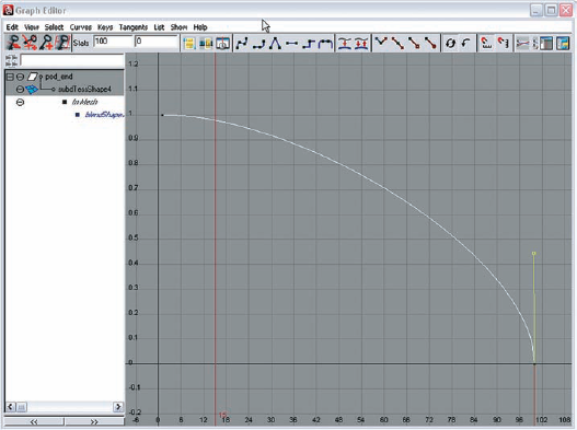
The animation looks good but it needs a little adjustment to make it more interesting. We'll edit the keys we set on the blend shape deformer using the graph editor.
With pod_end selected, open up the Graph Editor. Press the F key to frame the keys on the graph.
Adjust the keys so that the peapod grows slowly over time, starts to open, and then pops open. Adjust the handles on the graph to achieve this. You may need to convert the curves to weighted tangents. Try selecting the handles and choose (from the Graph Editor menu) Keys > Free Tangent Weight to get more control over editing the curve. Use Figure 4.12 as a reference.
Now that we have the sequence animated we can add some additional squirmy motion to the growth using a lattice.
Set the playhead at the end of the animation. Turn the visibility for the Peas layer on.
In the Outliner, select the pod_end object and the peas group, group them together, and rename the new group "peapod." Add the pod_split object to the blendshapes display layer and turn off visibility of this layer.
Select the peapod group and choose Deform > Create Lattice.
Set the S, T, and U Divisions for the lattice to 4, 8, and 4.
Switch to the front viewport to get a side view of the pod. Select the ffd1Lattice and the ffd1Base from the Outliner. Switch to the Move tool, hit the Insert key, and move the pivot point of the lattice up to where the peapod meets the stem (Figure 4.13).
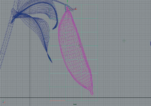
Using the Joint tool, create a series of eight joints moving down the side of the pod in a slight curve; use Figure 4.14 for reference.
Switch to the side view and move joint1 so that the chain goes down the center of the pod.
Select joint1 and ffd1Lattice. Choose Skin > Rigid Bind to skin the lattice.
With the lattice rigged we can animated the joints which will, in turn, animate the pod. Its kind of cool to see the pod growing while it's being deformed by the lattice.
In the Outliner, select joints 2 through 7. Move the playhead to the start of the Timeline. Turn off visibility for the Peas layer.
Switch to the Rotate tool and move it around to get a nice bend in the lattice.
Set a keyframe on the rotation channels for these joints. Move ahead 20 or 30 frames, rotate some more, and set another keyframe. We want a nice squirmy motion to the pod, but don't set more than three or four keyframes on the Timeline. Set the last keyframe at frame 90.
Open the Graph Editor with the joints selected and set Interpolation to Spline Tangents.
If the deformation of the peapod seems a little too harsh, open the Attribute Editor for ffd1Lattice, click on the ffd1 tab, and uncheck the box next to Local. This will make the lattice's deformation a bit smoother.
To add some additional creepiness, we'll make the eyes move around when the pod opens.
In the perspective window, use the Show menu to turn off visibility for deform-ers and joints.
Turn the visibility for the Peas layer back on.
Move to a point on the Timeline right before the peapod starts to split and select the peas group.
In the Channel Box, set a keyframe on the Visibility channel.
Move the playhead backwards in time one frame, set Visibility to 0 or off, and set another keyframe.
Create a locator and name it "lookAt."
Move the locator in front of the peapod.
In the Outliner, expand the peas group.
Select the lookAt locator and Ctrl+select the pea1 group. Choose Constrain > Aim > Options. In the options, reset the settings to the default value and create an aim constraint. Do the same for each of the other pea groups in the pod.
Move the playhead to the point where the peas become visible. Move the locator in front of the peapod and set a keyframe on its translation channels.
Move the playhead ahead on the Timeline 20 frames or so. Move the lookAtlo-cator around in space and set a keyframe. Create three or four more keyframes for different positions on the locator so that the eyes are constantly moving around.
Play the animation and marvel at its weirdness.
OK, the animation is kind of creepy. To really add some flavor, let's create the time lapse effect. This will increase the creepiness by a factor of 10, or 11 even!
In the Outliner, Ctrl+select joints 2 through 7, the lookAt locator, and the pod_end object. Open up the Graph Editor.
Press F to frame the keys on the graph.
Marquee-select all of the keys on the graph.
From the menu in the Graph Editor, choose Curves > Bake Channel > Options. In the options, set Time Range to Time Slider and Sample By to 3. Turn off Keep Unbaked Keys.
Click the Bake button. The curves now have a keyframe set at every third frame.
Marquee-select all the curves in the Graph Editor and choose Tangents > Stepped to change the interpolation to stepped.
When you play the animation, the peapod has the telltale steppiness of a time-lapse film. In the Timeline options, set Playback Speed to Real-Time to really see how the effect will look.
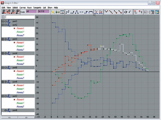
In the Outliner, select joints 2 through 7, open the Graph Editor, and frame the selection so you can see the curves for these joints.
Start randomly marquee-selecting keyframes and move them up or down. To really get a time-lapse look, you need random pops in the animation where the peapod has moved unexpectedly between exposures. Keep the timing the same, just move values up and down somewhat randomly. Don't go overboard though. Use Figure 4.15 as a rough guide. Your curves will look different as I left the rotation of the joints up to you, but you get the basic idea from looking at the graph.
Combining blend shape deformers, lattices, and joints is a great way to achieve a variety of interesting effects. Blend shapes can control growth while joints and lattices control movement. See if you can apply these tools and the time-lapse techniques to an animation of a flower blooming or a snowflake forming.
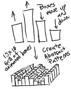
Our art director is working on a music video and would like some simple abstract animations to show the client. Her vision is something along the lines of simple moving shapes, somewhere between pistons and a piano keyboard. We'll see if we can do something with blend shapes that fits that vague description.
First we'll create a single animated brick using a blend shape and a simple control.
Open Maya and start a new scene.
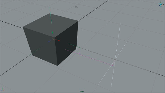
Choose Create > Polygon Primitives > Cube.
Make a duplicate of the cube and move it to the side.
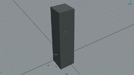
Select the top face on the duplicate cube, move it up four or five units, and scale it in a little.
Select the top face on the original cube and scale it out a little.
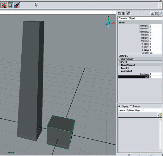
Rename the duplicate cube "tall1" and the original cube "short1."
Select the tall1 object and then Shift+select the short1 object. Switch to the Animation menu set and choose Deform > Create Blend Shape > Options.
Reset the options to the default settings and click the Create button to make the blend shape.
Select the short1 object. In the Channel Box, click on the blendShape1 node. Highlight the tall1 channel in the Channel Box, and MMB drag left and right in the perspective window to make sure the blend shape is working. You could also use the slider in the Window > Animation Editors > Blend Shape window (Figure 4.17).
The short cube should grow and shrink when you move the slider back and forth. If it's working correctly, delete the tall1 cube. The blend shape deformation controls will not be affected. Set the tall1 value on the blend shape node back down to 0 so that the cube is back at its original, short and squat shape.
We'll use the Distance tool to control when the blend shape animates based a locator.
Choose Create > Measure Tools > Distance Tool.
Click twice on the grid to create the two locators used for the tool. The measure indicator should appear between them.
Rename one of the locators "pin1" and the other "control1."
Select the short1 object and Ctrl+select the pin1 locator. Create a point constraint between these two objects so that pin1 snaps to the short1 object.
Turn grid snapping on and move the control1 locator so that it is two units away from the short1 object—it doesn't matter which axis, as long as the measure indicator is labeled 2 (Figure 4.18).
Switch to the Animation menu set and choose Animate > Set Driven Key > Set to open up the Set Driven Key window.
In the Outliner, choose Display > Shapes. Expand the distanceDimension1 node and select its shape node.
Click the Load Driver button on the Set Driven Key window.
In the Outliner, go to the Display menu and deselect DAG Objects Only. Scroll down and choose the blendShape1 node.
Click the Load Driven button on the Set Driven Key window.
In the Set Driven Key window, scroll down and highlight the Distance attribute in the upper-right section. Choose the tall1 attribute in the lower right and click the Key button.
Move the control1 locator on top of the pin1 locator so that the Distance is 0.
Set the blendShape1 node so that the tall1 value is 1 and the cube is extended and tall.
Click the Key button again in the Set Driven Key window.
Turn grid snapping off, select the control1 locator, and move it back and forth through the short1 object. The short1 object should interactively grow and shrink (Figure 4.19).
Duplicating the object with its input connections allows us to re-create the rig multiple times with just a few clicks.
Move the control1 locator so that it is on top of the pin1 locator. In the Out-liner, turn off shapes and turn on DAG Objects Only.
Turn off the Visibility for the distance dimension1 object.
Select the short1 object, the pin1 locator, and the distanceDimension1 object and group them; leave control1 outside of the group.
Name the group "brick1."
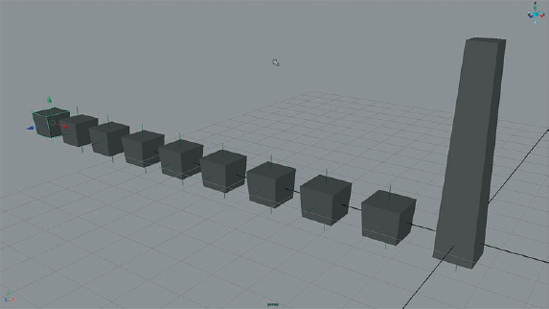
With brick1 selected, choose Edit > Duplicate Special > Options. In the options, set Group Under to World, set Number Of Copies to 9, and check the boxes next to Duplicate Input Graph and Assign Unique Names To Child Nodes.
In the Outliner, Ctrl+select all of the control locators. Group them and name the group "masterControl1."
Turn grid snapping on and select each of the bricks one at a time. Line them up two units apart on the grid in numerical order (Figure 4.20).
Select the masterControl1 group and slide it up and down the Z axis underneath the bricks. You should see each brick pop up in a wavelike fashion.
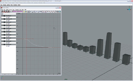
To make the motion of the bricks more interesting, we'll edit the driven keys on the Graph Editor.
Use the Display menu in the Outliner to make the DAG nodes visible again.
Shift+select all of the blendShape nodes and choose Window > Animation Editors > Graph Editor.
In the Graph Editor, hit the F key to focus on the keyframes. Marquee-select the animation curves. Set Interpolation to Flat Tangents and choose Curves > Post Infinity > Oscillate.
Move the masterControl locator back and forth again along the Z axis and see how the animation has been affected.
Experiment with the post-infinity settings on the curve. Also, try moving the second key to a different time value; try frame 8 and see how it affects the animation. Experiment with the interpolation of the curve as well as weighted tangents. You can have a lot of fun creating different wave shapes (Figure 4.21).
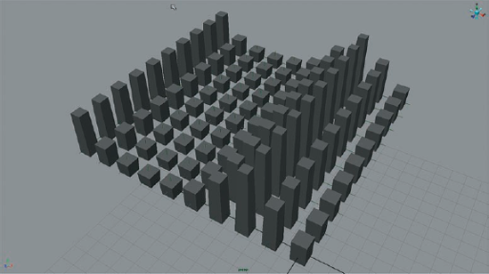
We can expand the row of animated bricks into an array by duplicating the group and its input connections.
In the Outliner, select the brick groups and the masterControl1 group. Group them together and name the new group "row1."
Duplicate the row1 group using Duplicate Special, and open the options for this action. Set Number Of Copies to 1 and leave Duplicate Input Graph checked.
Move the new row2 group over two units in X. Expand the group and select the masterControl2 group. Move it up and down in Z just to verify that the second group is being controlled the same way as the first.
Repeat this until you have a 10-by-10 grid of boxes (Figure 4.22).
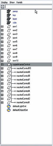
It's all about experimentation. Once the rig is completed, we can see what effect the master control groups have on the bricks.
In the Outliner, go through each of the row groups and move the masterControl groups out from under the row groups.
Select all the masterControl groups and group them together. Name the new group "superMasterControl" (Figure 4.23).
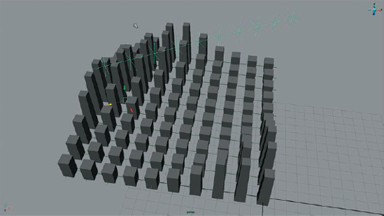
Move the superMasterControl group back and forth in Z and see what happens. Try moving it in X or rotating it in Y or Z. You should have some interesting results. Even scaling the group will create some neat effects (Figure 4.24).
The techniques used in this lesson can be used to create an endless variety of abstract animations, at least enough to pad your demo reel. Using a similar combination of blend shapes, measure tools, and set driven keys, see if you can create an interactive blend shape rig for a Venus flytrap or a puffer fish.
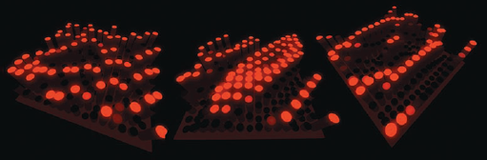
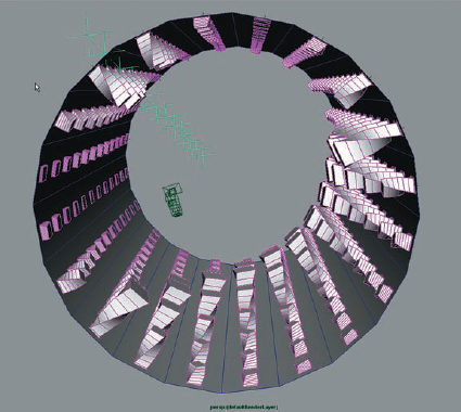
Other variations on these techniques can be seen in Figures 4.25 and 4.26.
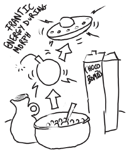
A commercial shot for a ridiculously sweet, and possibly lethal, children's cereal has fallen into your lap. The art director would like you to make a bowl of cereal transform into a cartoon-style bomb and then a UFO. She would like to see the transformation from one object to the next be somewhat erratic and spastic (somewhat like the behavior of the children after they eat this stuff). You need to create a rig for the effect that is easy to use so that the animator can take it from there.
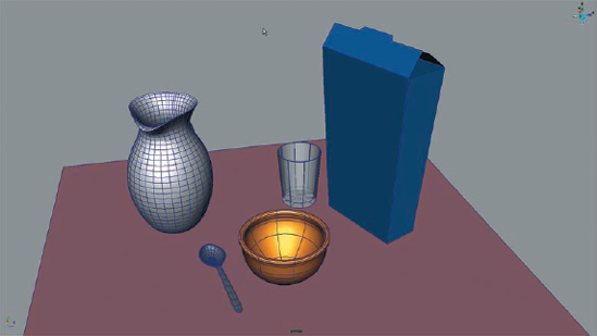
Open the
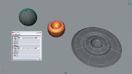
bowl_v01.mbscene from the Chapter 4 folder on the CD. You'll see a pleasant breakfast setting: a bowl, the cereal box, a spoon, a glass, and a jug of milk (Figure 4.27).Turn off the visibility of the objects' display layer and turn on the visibility of the blendShapes layer. You'll see the bomb and the UFO model. The bowl, UFO, and bomb are all NURBS objects. They have been created from the same profile curve, so their topology matches perfectly. This is required for the blend shapes to work properly.
The shot requires the bowl to turn into a bomb and then into a UFO. There are several ways we could do this. The most obvious way would be to create a blend shape sequence as we did for the peapod. However, in order to create the frenetic spastic metamorphosis effect, we will be using an animated fractal texture to control the blend shape weight value. If we use a blend shape sequence, the fractal noise applied to the weight value will cause the bowl to fluctuate between all three states. We want it to fluctuate between only two states at a time. The easiest way to do this is to layer the blend shapes and then create two sets of controls for each blend.
Select the bomb object, then Shift+select the bowl. Switch to the Animation menu set and choose Deform > Create Blend Shape > Options. Make sure the Local button is selected and that In-Between and Delete Targets are not selected. Create the blend shape.
Open the Attribute Editor for the bowl and click on the blendShape1 tab. Rename blendShape1 "bowl2Bomb."
Select the UFO object and Shift+select the bomb object. Create another blend shape with the same settings and name it "bomb2UFO."
Choose Windows > Animation Editors > Blend Shape to open up the blend shape controls. In the options for the Blend Shape window, set the Orientation to Horizontal so both sliders are clearly visible.
Move the slider on the bowl2Bomb control to 1. You should see the bowl turn into the bomb (Figure 4.28).
Move the slider on the bomb2UFO control to 1. Now both bomb shapes turn into the UFO.
Animated fractal textures are a great way to add frenetic energy to an animation. In this case we'll apply the textures to the values of the blend shape deformers.
In the Outliner, open the Display menu and turn off the DAG Objects Only option.
Select the bowl2Bomb blend shape and MMB drag it to the work area of the Hypershade. Do the same for the bomb2UFO shape.
Scroll down in the Create Nodes menu on the Hypershade and click twice on the Fractal texture (under 2D Textures) to create a couple of fractals.
Name one of the textures "bowl2BombFractal" and the other "bomb2UFOFractal."
Right-click in the work area of the Hypershade and choose Graph > Rearrange Graph to make things a bit clearer.
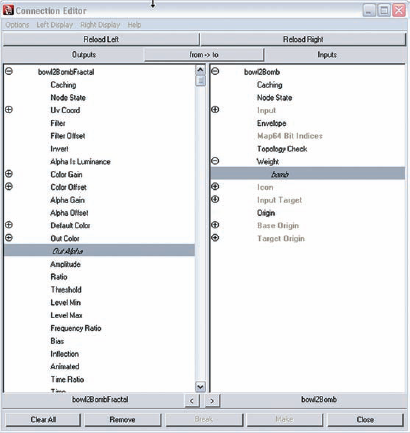
MMB drag the bowl2BombFractal texture on top of the bowl2Bomb blendShape node. Choose Other from the pop-up menu to open the Connection Editor.
On the left side of the Connection Editor, highlight Out Alpha. On the right side, expand the Weight attribute and highlight bomb, just like what's shown in Figure 4.29. The bowl should change into something between the bowl and the bomb, like a freaky apple.
Open the Attribute Editor for the bowl2BombFractal texture. Click the box next to Animated.
Rewind the animation, right-click over the field next to Time, and choose Set Key.
Move to frame 200, move the Time Slider on the bowl2BombFractal Attributes to 100, right-click, and set another key.
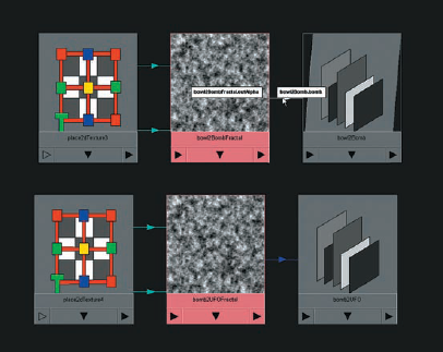
Repeat steps 6 through 10 for the bomb2UFOFractal texture (Figure 4.30).
If you play the animation now, you should see the bowl spastically morph between the bomb and UFO shapes and the bomb spastically morph between the bomb and UFO shapes. We need to set up a control so that the animator can easily determine which shapes will appear in the sequence.
Create a locator and name it "blendControl."
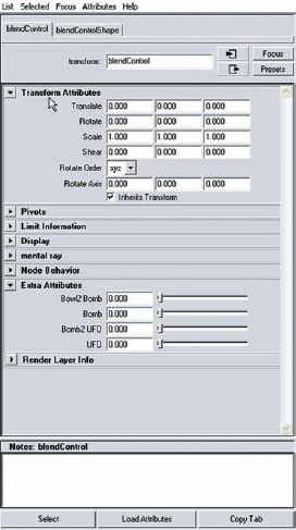
Open the Attribute Editor for the blendControl locator and, from the menu at the top of the editor, choose Add Attributes.
Name the attribute "bowl2Bomb." Set it to Float and set a Minimum value of 0, a Maximum value of 1, and a Default value of 0. Click the Add button to create the attribute without closing the Add Attribute Editor.
Add three more identical attributes. Name them "bomb," "bomb2UFO," and "UFO" (Figure 4.31).
Open the Hypershade and switch to the Textures tab in the upper area.
Choose Window > General Editors > Connection Editor to open the Connection Editor. Select the blendControl locator and load it on the left side by hitting the Reload Left button.
In the Hypershade, select the bowl2BombFractal texture and load it on the right.
On the left side of the Connection Editor, select the bowl2Bomb attribute; on the right side, select the Alpha Gain attribute.
On the left side, select the Bomb attribute, and on the right side select the Threshold attribute.
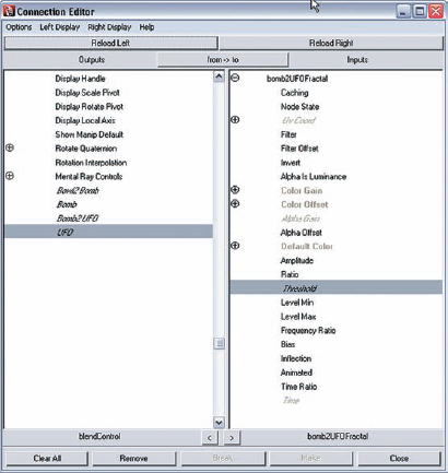
From the Hypershade, select the bomb2UFOFractal texture and load it on the right side of the Connection Editor.
Select the bomb2UFO attribute on the left and the Alpha Gain on the right.
Select the UFO attribute on the left and the Threshold attribute on the right (Figure 4.32).
With the controls set up, animating the scene is easy.
Play the animation. Nothing should happen; all the controls are at 0. Open the Attribute Editor for the blendControl locator and expand the tab under the Extra Attributes folder.
With the animation playing, slide up the bowl2Bomb attribute. You should see the bowl fluctuate between the bowl and bomb shapes.
With the animation playing, slide up the Bomb attribute. When the slider is at 1, the bowl has turned completely into the bomb.
Now slide up the bomb2UFO attribute. The bomb now fluctuates between the bomb and UFO shapes.
Slide up the UFO slider and the shape now rests as a UFO, ready to fly off for some sugar-fueled adventures.
Set all the attributes to 0 again and set the playhead to frame 30.
In the Attribute Editor for the blendControl, right-click over the field for the bowl2Bomb attribute and choose Set Key.
Move to frame 50, set the slider to 1, and set another keyframe on the bowl2Bomb attribute.
While still on frame 50, set a key on the Bomb attribute.
Move to frame 60, set Bomb to 1, and set another keyframe.
Move to frame 90 and set a keyframe on the bomb2UFO attribute.
Move to frame 110 and set bomb2UFO to 1; set a keyframe.
While still on frame 110, set a keyframe on the UFO attribute.
Move to frame 120, set UFO to 1, and set a keyframe.
Turn the visibility for the blendShapes layer off and turn on the visibility for the object layer. Play the animation and check the results.
To get the controls to work, we've used the Alpha Gain and Threshold attributes on the fractal textures as a sort of volume control for the fractal animation. Both Alpha Gain and Threshold have value ranges from 0 to 1. You can open the Hypershade and zoom in on the textures and see that by turning the Bomb or UFO controls up, the fractal textures turn white, meaning a value of 1. When the value is 1, the connection to the blend shape node causes the value of the respective blend shape to be 1. The texture is blown out so that the animated fractal texture, while still going on in the background, has no effect on the value of the blend shape. The Alpha Gain has a similar but opposite effect. It's not visible in the texture swatch in the Hypershade, but since the Alpha Gain is controlling the blend shape, when it's at 0, the fractal animation has no effect on the blend shape; when it's at 1, the fractal animation is at full strength and the spastic morph it clearly visible. The advantage of putting all these controls on the locator is that they can all be edited at once in the Graph Editor.
Creating a chain of blend shapes in this manner works well for some situations. Once again we see how the animated fractal texture can create some interesting effects. The following are some suggestions on how to enhance the scene or use these techniques for other projects.
Create some particles and set the render type to sphere, fill the bowl with particles, and set the bowl object as a collision object. See if you can get the cereal to fly out of the bowl during the transformation.
Apply this effect to models of faces. See if you can re-create something similar to the person-to-agent morph effect from The Matrix.
To add some springy secondary motion, turn the bowl object into a softbody.