3
Intelligent Local Controllers
3.1 Introduction
The development and use of the intelligent local controllers for microgenerators and controllable loads enables stable microgrid operation. These controllers provide efficient voltage and frequency control in case of islanded operation, ancillary services in interconnected mode, and deal efficiently with frequency and voltage variations during transitions from interconnected to islanded operation and vice versa.
The main tasks of microsource controllers are to allow power sharing between the different sources at different locations, acting on the electronic converters that interface them to the network. As communication lines, especially for long distances and control purposes are expensive and vulnerable, at least fast communication should be avoided. This can be achieved by using local controllers, which are based on frequency and voltage droops. This way, the locally available information – frequency and voltage – is used for power sharing. Normally, the frequency is linked to the active power, and voltage is linked to the reactive power.
Standard rotating generator systems inherently support these droops. Sometimes, for improving performance, additional controllers are applied. Therefore it is possible to operate large numbers of such generators in a single network. However, with standard static inverters, characterized by fixed frequency and voltage, such an approach is not possible. A control approach providing frequency and voltage droops is required.
In this chapter, intelligent control concepts for power electronics interfaced microsources are described. Control strategies for multiple inverter systems are developed with reference to the self-synchronizing mechanism of conventional rotating generators. The appropriate control of frequency and voltage in each inverter facilitates the sharing of the active and reactive power in the system. Simulation results that demonstrate power sharing between distributed generators are given. In the following, the implications of line parameters, in particular of the high resistance practically found in LV microgrids, are systematically discussed. Finally, a control algorithm using the fictitious impedance method is analyzed and characteristic simulation results are provided.
3.2 Inverter Control Issues in the Formation of Microgrids
3.2.1 Active Power Control
The basic principle that allows classic synchronously rotating generators to change their power output in response to a change in the system load without an explicit communication network is the frequency variation at the machine terminal as a function of power demand. When two points in the network are operating at different frequencies there is an increase of active power delivery from the location of higher frequency to the location of lower frequency. As this happens, the two frequencies tend to drift towards a common average value until the new steady state is reached (self-synchronizing torque). This physical relation between active power output and frequency in the synchronous generators has to be implemented in the control of the inverters, in the case of a system with inverter interfaced sources.
3.2.2 Voltage Regulation
Voltage control must ensure that there are no large circulating reactive currents between sources. Without local voltage control, systems with high penetration of microsources could experience voltage and/or reactive power oscillations. The issues are identical to those involved in the control of large synchronous generators. However, in large power systems the impedance between generators is usually large enough to impede circulating currents. In a microgrid, that is typically radial, the problem of large circulating reactive currents is immense. With small errors in voltage setpoints, the circulating current can exceed the ratings of microsources. This situation requires a voltage vs. reactive current droop controller so that, as the reactive current generated by the microsource becomes more capacitive, the local voltage setpoint is reduced. Conversely, as the current becomes more inductive, the voltage setpoint should increase.
3.3 Control Strategies for Multiple Inverters
3.3.1 Master Slave Control Scheme
The control method that has been used for paralleling inverter units in the case of UPS systems is very difficult to adopt for a distributed generation application like the microgrid. The load current may be measured and divided among the participating inverter units, but this requires that the load and the microsources are separated.
In the master–slave control, one inverter regulates the voltage and the resulting current of this unit defines the current references of the other units. The master acts as a voltage source inverter and the rest of the units as current source inverters [1].
A system with a voltage source, as master and additional controllable current sources (grid supporting units) is depicted in Figure 3.1. The supervisory control is responsible for power distribution. The main features of this approach can be summarized as follows:
- a simple control algorithm at component level is required
- high expenditure for buses and their cabling is needed
- the system is difficult to expand
- supervisory control is required
Figure 3.1 Principle of a (classic) modular supply system consisting of one voltage source, current sources and passive loads
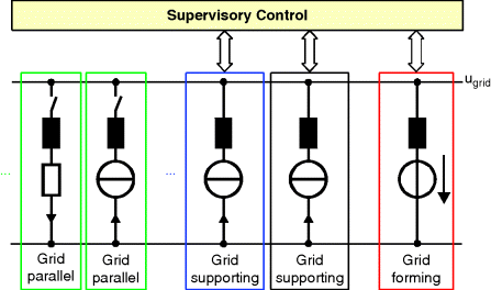
As a result, this approach is not suitable for the operation of systems based on distributed generation, mainly due to high communication requirements and the needs for supervisory control and extra cabling, even for small systems.
3.3.2 Multi-Master Control Scheme
Communication and/or extra cabling can be avoided, if the inverters themselves set their instantaneous active and reactive power. In [2] a concept has been developed that uses reactive power/voltage and active power/frequency droops for the power control of the inverters (Figure 3.2). Droops function in a similar way to those used by conventional rotating machines in large systems, as discussed in Section 3.2. The supervisory control just provides parameter settings for each component, which may comprise the idle frequency f0 and voltage u0, the droop slopes and any other additional, basic as regards the communication requirements, command. In this way, expensive communication systems to relay control signals to each inverter unit are avoided. Grid quantities, voltage and frequency, which are locally available are used for the inverter control. The system is formed by paralleling the voltage source inverters (VSIs) that interface the microsources via their filters and the network impedances. The benefits of this approach are the following:
- simple expansion of the system
- increased redundancy with VSI paralleling. Master/slave operation is abandoned and the system does not rely on vulnerable communications.
- optimization based on a simple bus system.
- a simplified supervisory control with more complex control tasks assigned to the components.
Figure 3.2 Frequency and voltage droops. Reproduced by permission of Technology & Science Publishers [9]

Two inverters in parallel are shown in Figure 3.3, considering only the output voltages at the fundamental frequency. The inverters are coupled via the inductances resulting from cabling and harmonic filters. The active power P and the reactive power Q of the voltage sources coupled by inductors with negligible resistance can be calculated as follows:
(3.1)
![]()
and
Figure 3.3 Voltage sources coupled via inductors (a) equivalent circuit (b) phasor diagram
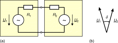
A phase shift δ between two voltage sources causes active power flow, while reactive power flow is due to voltage difference U 1 − U 2. Assuming standard values for the inductances L 1, L 2, results in very sensitive systems, where even small deviations of the voltage phase and magnitude cause high current flows between the inverters. This sensitivity is the reason why fixed frequency and voltage inverter concepts fail. There is always a voltage difference due to tolerances of the sensor, references, temperature drift and aging (e.g. 1–5%). Also, crystals used for the time reference are not identical, and the angle difference is the integral of the frequency error over time. Therefore, precise control with complex algorithms is required for the parallel operation of voltage source inverters.
A precise active power dispatch is required for balancing demand and generation. Applying droops, two approaches are possible: P (f) and f (P) that is, measuring frequency and defining active power output or vice versa.
3.3.3 Droop Control Implementation in the VSI
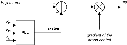
The direct control system analogy of the droop line, as applied to synchronous machines, is to measure system frequency and control real power (Figure 3.4). System frequency is measured with a phase-locked loop (PLL) technique, which operates based on the three-phase terminal voltage. The system frequency is compared with a reference value (typically 50 Hz under normal operation). The frequency deviation is filtered using a low-pass filter and multiplied by a gain constant to obtain the droop control [3].
Figure 3.4 Block diagram of the VSC control for frequency regulation
For mainly inductive power systems, that is, systems with a high ratio of reactance to resistance (X /R), (Eq. 3.2) expresses the fact that differences in voltage cause reactive power flows, or conversely, reactive power flows influence terminal voltages. Typically therefore, reactive power is controlled by a Q vs. V droop, as shown in Figure 3.2 [3].
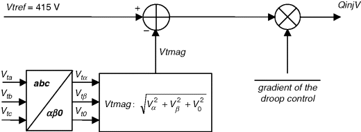
Figure 3.5 shows the block diagram of the voltage regulation control technique. Three-phase terminal voltages (V ta, V tb, V tc) are measured and fed as inputs to the controller. The magnitude of the terminal voltage vector (V tmag) is calculated and compared with the set reference value (e.g. V tref = 415 V). The voltage error is filtered by a low-pass filter and multiplied by a gain constant to obtain the droop control of the VSC. The output of the voltage regulation control block provides the reactive power (Q injV) that needs to be injected to maintain the terminal voltage according to the droop set value.
Figure 3.5 Block diagram of the VSC control for voltage regulation
However, it is not straightforward to obtain accurate measurement of instantaneous frequency in a real system. Measuring instantaneous real power is easier. It has therefore been proposed [4–6] that control is implemented in the opposite way, that is, the output power of the voltage source converter is measured and this quantity is used to adjust the output frequency, as shown in Figure 3.6. Similarly, reactive power is measured and used to adjust the voltage magnitude. Active and reactive power are estimated from the inverter voltage and output current in the power acquisition block. A first-order delay is used for passing through each of the P, Q values. These may be part of the power measurement filters and serve to decouple the two control channels and to adjust the time frame within which the inverter frequency and voltage change with respect to power changes. The droop controls are applied next, to define the voltage reference of the inverter. Active power determines the frequency and reactive power determines the voltage magnitude through the respective droops. It is also noted that a phase correction is introduced in direct proportion to the measured active power. This branch enhances the system stability.
Figure 3.6 Control strategy based on power acquisition [4]. Reproduced by permission of Technology & Science Publishers [9]
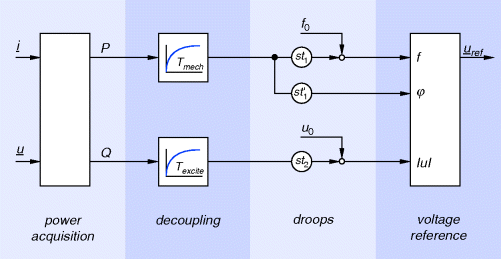
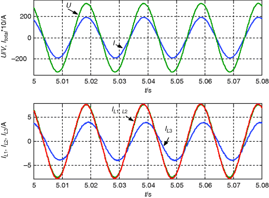
Figure 3.7 shows power sharing among three SMA Sunny Island™ single phase inverters programmed with this scheme (rated power 3.3 kW, clock 16 kHz, coupling inductor 0.8 mH). They are connected to a resistive load, each with an LV cable of approximately 10 m. The frequency droop of the inverters denoted by L 1, L 2 was set to 1 Hz/rated power, while the droop of the inverter denoted by L 3 was set to 2 Hz/rated power. It is evident that this method allows the L 3 inverter to supply half the power of the other two and that active power sharing is defined by the droop constants. It is remarkable that reactive power is circulating – as seen from the inverter current – as a result of the phase difference caused between inverter L 3 and L 1, L 2.
Figure 3.7 Parallel operation of three identical inverters sharing a resistive load via their frequency vs. power droop control. Reproduced by permission of Technology & Science Publishers [9]
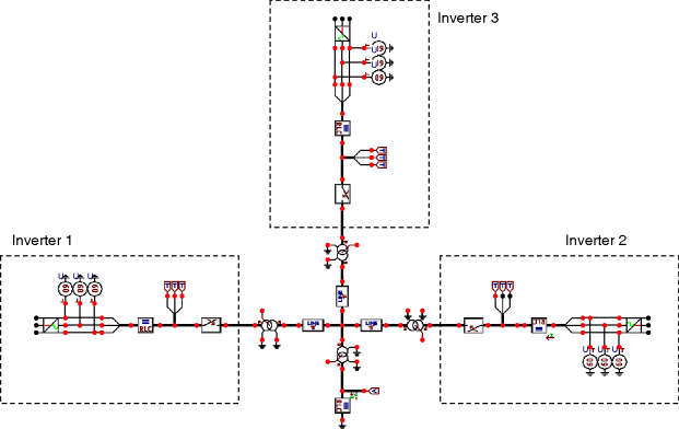
Next, a simulated case of a microgrid is presented. The microgrid (Figure 3.8), consisting of three inverters coupled via an MV distribution system (15 kV), is simulated in ATP/EMTP (alternative transients program/electromagnetic transients program: http://www.emtp.org/). The inverters are represented by controllable three-phase voltage sources, and the distribution system consists of switches, overhead lines (π-blocks), transformers and the load. The three inverters operate in parallel via the MV distribution system and supply a resistive load with a total power of 100 kW. The inverters are controlled with the algorithm described in Figure 3.6.
Figure 3.8 Simulation of inverter dominated system in ATP/EMTP
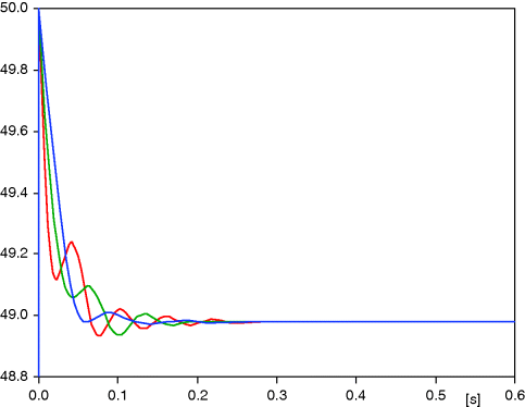
With suitable setting of the slope of the frequency droop the contribution of the inverters is 20, 30 and 50 kW, as seen in Figure 3.9. The slope of the frequency droop may be used in order to take into account the size of the inverter. The idle frequency f 0 can be used to control the energy flow. The idle frequency of the inverters in this case is set to 50 Hz. Owing to the load, the system frequency decreases to 49 Hz (Figure 3.10). The frequency could be restored to 50 Hz with the use of a secondary control.
Figure 3.9 Load shared between the three inverters
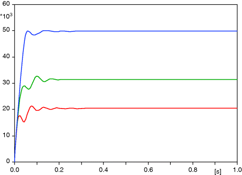
Figure 3.10 Frequency change in the islanded microgrid
The setting of the slope of the voltage droop results in a variable virtual inductance between the respective inverter and the distribution system. It should be chosen in order to ensure stable operation. The idle voltage should be set in order to minimize reactive power. However, voltage limits have to be respected.
3.3.4 Ancillary Services
While in grid-connected mode, microgrids can contribute to the overall grid control and thus facilitate the operation of the system by providing ancillary services.
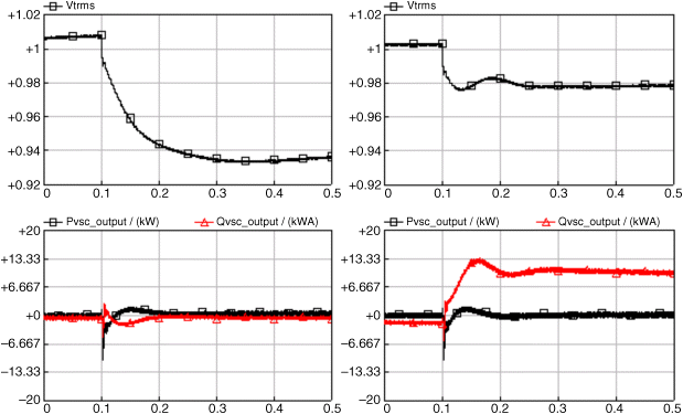
A microgrid can support voltage in the area of its connection to the upstream network, in the event of a disturbance that causes a voltage drop. Figure 3.11 shows the simulation results for the sudden reduction of voltage at the point of common coupling (PCC) of a microgrid that is connected at the end of a long supply feeder with and without voltage regulation. The microgrid with voltage regulation, in this case the VSC of an energy storage unit, injects reactive power to maintain the rms terminal voltage (V trms) within acceptable limits.
Figure 3.11 Simulation results without (a) and with (b) voltage regulation control of the microgrid connected to main supply
The central controller effectively sets the droop line slope of the individual VSC interfaces to determine reactive power sharing between the units and the reactive power export/import of the microgrid under grid-connected operation. During islanded operation the net reactive power flow will be zero. The voltage in the microgrid will then increase (if there is excess reactive power), forcing power electronics interfaced units to produce less Q or even absorb reactive power, until a new steady-state voltage is reached (net zero Q flow).
Here the voltage/reactive power droops act in order to limit the reactive power flow. The voltage control and the flow of reactive power in LV grids, which are mainly resistive, are discussed in the following paragraphs.
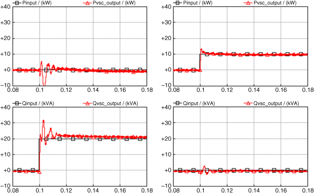
A microgrid can absorb/inject a specified amount of aggregate power at the point of common coupling. This is carried out by adjusting the position of the droop lines of the individual VSCs from a central controller. A simulated case is shown in Figure 3.12. This adjustment does not require a particularly fast control loop, since even a slow telecommunications link has time constants significantly faster than most power network subsystems. The additional active and reactive powers (Pinj, Qinj) to be injected in this case are set by the central controller for each specific VSC. Alternatively, the droop line settings could have been adjusted for each VSC by the central controller directly. In the system simulated, two limit blocks are used to limit the power injection (active power limits ±10 kW, reactive power limits ±20 kVAr). These limits are important during the transient period caused by a disturbance in the system.
Figure 3.12 Simulation results with the active and reactive power control set by central controller (all other controls are deactivated and the microgrid is connected to the main supply)
3.3.5 Optional Secondary Control Loops
If a microsource has to produce a specific active power during the isolated operation, a secondary control action may be employed. The control forces the active power output of the VSI to remain at P ref while the system frequency changes, by acting on the f ref value. The droop line is shifted vertically as shown in Figure 3.13.
Figure 3.13 Control action for constant active power production at P ref
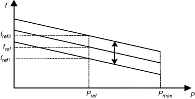
The microgrid frequency will end up in steady state after every load change to a value different from nominal that depends on the droop slope and the relation between the load and frequency. To restore the frequency to the nominal value, a secondary control loop is needed to cancel out the residual difference. The control action changes the P ref value so that the frequency is always brought back to the f ref value. The droop line is shifted horizontally as shown in Figure 3.14.
Figure 3.14 Control action for microgrid frequency recovery at f ref
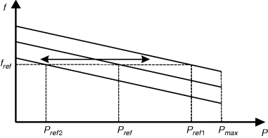
Likewise, secondary control action can be applied to the voltage/reactive power control. Reactive power output of the VSI may be kept to a constant value Q ref by changing the V ref value and shifting the droop line vertically as in Figure 3.13 for active power. To keep the output voltage of the inverter constant, Q ref may be changed, shifting the droop line horizontally as is done in Figure 3.14 for frequency.
3.4 Implications of Line Parameters on Frequency and Voltage Droop Concepts
LV grids are characterized by a high ratio of resistance to reactance, thus mainly resistive coupling exists among the VSCs. In this case, active power seems more appropriate for controlling voltage. This is done, for example, with dynamic voltage restorers in order to compensate voltage sags (short-term interference).
The use of active power flow for voltage control would have financial consequences – it would change completely the meaning of economic active power dispatch. Also the compatibility with rotating generators in the LV grid and the upwards compatibility with the main grid would be lost.
The function of voltage/reactive power droops in the LV grid is to limit reactive power flows. Keeping the voltage in the allowed range should be done by a suitable layout of the LV lines and eventually taking care to increase the reactive part of the lines with the addition of chokes.
In this section, we analyze the effect of the network line parameters in the application of the droop control of the VSI units that form the microgrid.
3.4.1 Power Transmission in the LV Grid
Table 3.1 shows typical line parameters, R′, X′, and typical rated currents for HV, MV and LV lines. It is clear that the assumption about inductively coupled voltage sources for representing the droop controlled inverters in the distribution system is only correct for HV lines. MV lines have parameters with similar resistive and reactive parts, while LV lines are even predominantly resistive.
Table 3.1 Typical line parameters [7]

The active power P inv and the reactive power Q inv of resistively coupled voltage sources – here an inverter and a grid – can be calculated as follows, with the notation adopted in Figure 3.15:
Equation (3.4) shows that, in LV grids active power flows are coupled with voltage, while phase difference between the voltage sources causes reactive power flows (Eq. (3.3)). This fact suggests using active power/voltage and reactive power/frequency droops – hereinafter called “opposite droops”– in the LV grid, instead of reactive power/voltage and active power/frequency droops –“conventional droops”.
Figure 3.15 Resistively coupled voltage sources. Reproduced by permission of Technology & Science Publishers [9]

3.4.2 Comparison of Droop Concepts at the LV Level
In the following, the advantages and disadvantages of using conventional or opposite droops at the LV level are summarized in Table 3.2.
Table 3.2 Comparison of droop concepts for the LV level
| Conventional droop | Opposite droop | |
| Compatible with HV-level | yes | no |
| Compatible with rotating generators | yes | no |
| Direct voltage control | no | yes |
| Active power dispatch | yes | no |
As seen in Table 3.2, the only advantage of using opposite droops is the direct voltage control. But if the voltage was controlled in this way, no power dispatch would be possible. Each load would be fully supplied by the nearest generator. As this is generally not possible, voltage deviations would remain in the grid. Using conventional droops results in connectivity at the HV level, allows power sharing with rotating generators and provides a precise power dispatch. The voltage deviations within the grid depend on the grid layout, which is today's standard.
3.4.3 Indirect Operation of Droops
Basically, the conventional droop approach can be applied in LV grids owing to the generator voltage variation with reactive power exchange. The reactive power of each generator is tuned in a way that the resulting voltage profile satisfies the desired active power distribution. In the LV grid, the reactive power is a function of the phase angle, as seen in (Eq. 3.3). This is adjusted with the active power/frequency droop. Of course, the entire loop has to be consistent. Four stable operating points depending on the slopes of the droops can be distinguished, two of which make sense [8,9].
3.4.3.1 Stable Operating Points
In order to derive the operating points of conventional droops in LV grids, the stability of the power transfer (Eq. 3.4) is assessed in a simplified manner. Since at a reasonable operating point, δ is rather small, cos δ becomes almost 1. Rearranging (3.4) with given power P inv and given grid voltage U grid, two solutions for the inverter voltage U inv are obtained from the quadratic equation:
Both solutions are considered next. U inv 1 is a voltage close to the grid voltage and U inv 2 is a slightly negative voltage. This implies a 180° phase shift. Therefore, in (3.6) the factor k is introduced, with k 1 = 1 for the first solution and k 2 =− 1 for the negative solution. The factor k is an approximation of the cos function in (3.4):
The inverter power P inv is adjusted by changing the inverter voltage U inv with its reactive power, as follows:
(3.7) ![]()
From (Eq. 3.3) Q inv is a function of the angle δ, for small values of which
(3.8) ![]()
δ is the integral over time of the generator's frequency difference from the grid frequency:
(3.9) ![]()
and
The integral character of this process ensures the above-mentioned precise power distribution. With backward substitution from (3.10) to (3.6) and solving for P inv:
(3.11) 
which describes a first-order lag equation with solution:
This simplified solution is obtained by the assumptions that U inv is constant with time and that the power acquisition's dynamic is neglected. Equation (3.12) is stable, only if the constant C is positive, which means that
with p droop and q droop as the respective droop factors. The four stable operating points derived from (3.13) are summarized in Table 3.3.
Table 3.3 Stable operating points of conventional droops in LV grids

Cases 1 and 2 (the inverse conventional and the conventional droop) are characterized by the same sign of both droop factors. This requires k to be 1, which results in an inverter voltage which is near the grid voltage (3.5). Only little reactive power is needed to tune the voltage, whereas in cases 3 and 4, huge reactive power is needed. Even worse, the inverter power and a huge amount of grid power are dissipated in the line. Therefore, cases 3 and 4 are unacceptable.
3.4.3.2 Simulation
In this paragraph, the inverter voltage U inv, the grid voltage U grid and the voltage drop across the line U line are simulated for all four cases of Table 3.3. A single phase system is modeled assuming a line resistance of 0.5 Ω. The injected inverter power is 10 kW. The results were obtained using the simulation tool Simplorer™.
Figure 3.16 Comparison of droop concepts. Reproduced by permission of Technology & Science Publishers [9]
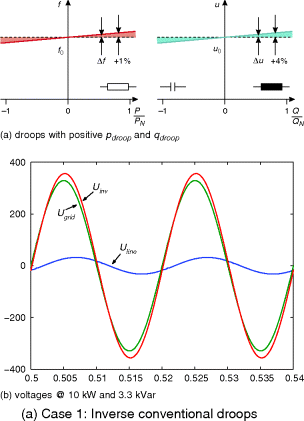
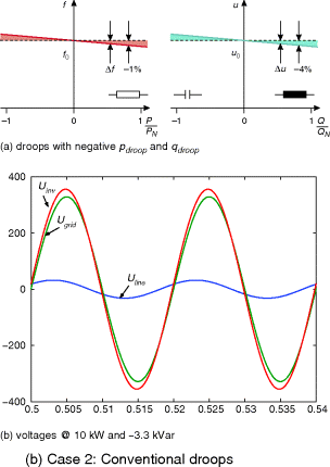
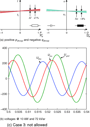
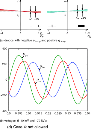
It can be concluded that the conventional droops (Case 2) can be equally applied to LV grids. They provide a reasonable operating point and the advantages of Table 3.2.
3.5 Development and Evaluation of Innovative Local Controls to Improve Stability
For effective control of the microsources, the dependence on the line impedance has to be overcome. To this end, a supplementary control technique that is, in effect, an elaboration of the active power/voltage angle, reactive power/voltage magnitude discussed previously, has been proposed; it is called the fictitious impedance method [10]. It uses the instantaneous current feedback, thus providing additional possibilities such as control of the harmonic frequencies. This section describes its implementation and analyzes the results by using simulations.
A voltage drop is imposed on the inverter output formed by the inverter current across a fictitious impedance. This impedance value is a control parameter and is defined at will, according to the conditions of the network or the microsource/inverter stage of operation. Therefore, it constitutes a flexible means of adjusting the inverter to the system. The effectiveness of the control is tested under all formed line characteristics that may be encountered, from fully inductive to mostly resistive. The aim is to decouple the P/f and Q/V control channels, changing the behavior of the inverter, and leading to a system with inductively coupled sources.
In the following paragraphs, results from stability analysis of distribution networks with resistive and inductive coupling impedances are provided with the main emphasis on resistive coupling, which is more common in LV networks and the one that provokes more stability problems. The alternative transient program (ATP) is used for the simulations.
3.5.1 Control Algorithm
In order to simplify simulations, all sources are considered as fully controllable, three-phase balanced voltage sources. This is an acceptable simplification, since the inverter allows the control of the output voltage waveform.
The output impedance of a source facilitates its parallel connection with other sources, and the formation of the system. In the case of the microsource inverter, this impedance is assumed to be the coupling transformer leakage inductance or the inverter filter reactance. In addition to this output impedance, the line impedance must also be taken into consideration. In the LV network this is mainly resistive but it is modeled as a series connection of resistance and reactance to take into account all possibilities.
As discussed, the strong coupling of real and reactive power in LV affects the droop control techniques. In order to solve this problem, a fictitious impedance is introduced to change the behavior of the coupling between inverters and to improve the system stability. An outline of the control is shown in Figure 3.17. In order to avoid harmonics and voltage unbalances, the output current is filtered first and the resulting positive sequence is multiplied by the impedance and then added to the output voltage.
Figure 3.17 Control of voltage and frequency
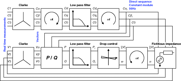
In summary, the following steps are involved:
- current is measured and filtered
- active and reactive power are calculated using the output voltage
- P and Q power is filtered to smooth the response
- droop controls are applied
- output fictitious impedance is simulated
The fictitious impedance constitutes an additional control variable. It can be defined arbitrarily in terms of magnitude and angle. It can be reactive, resistive or of any ratio in between. It is noted though that, contrary to a physical resistance, the fictitious resistance implies no losses, and the efficiency of the inverter is not compromised [11].
In detail, the algorithm steps are as follows:
It is remarkable that the Q/V droop can be eliminated, because the effect of the reactive power flowing through the fictitious impedance is a voltage drop, with the same slope direction as the Q/V control droop. Therefore, both can be considered as complementary control strategies or, in order to simplify the control algorithm, an equivalent voltage drop may substitute for the Q/V droop result.
The reaction time and the frequency response of the digital filters operate as the inertia of the conventional rotating mass generators. If the response is too slow, the device will react as a heavy rotor machine. The response will be slow and the high-frequency variations of power will be negligible. On the other hand, if the time response of the digital filter is fast, the device will appear as a low inertia power source and any variation of the output power will affect its frequency. If the power consumption in the microgrid changes considerably, the devices with bigger inertia (e.g. with slower filters) will absorb most of the power fluctuations.
The magnitude of the fictitious impedance is usually chosen higher than that of the filter impedance so that it dominates the total output inverter impedance. An inductive fictitious impedance may alter the picture in a predominantly resistive LV network and enhance system stability, avoiding the necessity to increase the filter inductance. The resistive part can reduce the high frequency oscillations that appear with a predominantly inductive coupling as will be discussed. The resistive component could also be employed to share unbalanced currents and harmonics.
Choosing the fictitious impedance inversely proportional to the rated power of the inverter would automatically lead to current sharing of the inverters in proportion to their rating during transients and in steady state. The following simulations are performed with devices of the same power to more easily compare the results.
3.5.2 Stability in Islanded Mode
In order to compare the response of the proposed algorithm with the conventional droop control, the following microgrid (Figure 3.18) is simulated, assuming islanded operation.
Figure 3.18 Simulated microgrid layout
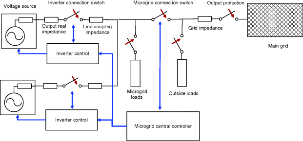
The system comprises two inverters connected to a set of active and reactive loads. The inverters are coupled in parallel, and each inverter is composed of a three-phase voltage source, the three-phase connection switch, the actual output impedance and the line coupling impedance. Inverters are sized at 10 kW with a droop control characterized by 1 Hz difference between zero and maximum power output. The value of the output inductance in use is 0.15 Ω. Taking into account that the device nominal power is 10 kW, the output impedance, expressed in p.u. (per unit), is around 1% of the characteristic impedance. This rather low value is an adverse factor to the stability of the resulting system.
In this section and the next, the benefits of the proposed control are established at islanded operation, where the self synchronization and load sharing are important under different coupling conditions – resistive and inductive. Nevertheless, the control is also assessed when the system is connected to the grid, considering operations such as additional inverters being connected, synchronization and grid reconnection with subsequent disconnection, as well as the dynamics of the primary energy source.
3.5.2.1 Inductive Coupling
The first study case compares the performance of the droop control with and without the fictitious impedance. The value of the reactance considered in the simulations is 1–5% of the characteristic impedance of the devices.
In the droop-alone control scheme, simulations demonstrate that the system is more stable if the coupling inductance is high, around 5% in each inverter, 0.7 Ω and 0.8 Ω. The line should have a small resistive component to damp the high frequency (close to the fundamental) oscillations of power. The cut-off frequency of the low-pass filters may be reduced to eliminate the high-frequency oscillations but then the system may become unstable after exposing slower power oscillations in the region of the classic machine stability owing to the droop control. These latter oscillations are dependent on the droop constants and the value of the coupling reactance. For example, with smaller values of the inductance, system stability is difficult to achieve if the cut-off frequency of the filters is not increased. It becomes evident that combining measures to tackle these two stability issues is not an easy task in all practical situations. Using the fictitious impedance method, stability is easier to achieve in all situations.
In the following simulations, both inverters are synchronized at the nominal frequency (50 Hz) at time 0.1 seconds, with no initial power output and with a connected load of 1800 W, 400 VAr (inductive). Figure 3.19 shows the behavior of the control with purely inductive coupling. The control starts working properly, but a few milliseconds later the power starts to oscillate and the system becomes unstable. If a small resistive component, say 0.05 Ω, is included in the coupling between the inverters, the oscillations die out. This is a small resistance that every LV coupling is expected to have, so it can be said that the system is stable.
Figure 3.19 Output power of each inverter with totally inductive coupling and traditional drop control
The coupling reactances of the inverters are 0.7 and 0.8 Ω and the cut-off frequencies of the first-order filters are 20 Hz and 10 Hz for the current and power filter respectively.
When the coupling reactance is reduced in further simulations, it is shown that the system fails to reach stability. Therefore, the droop method alone does not seem robust enough to connect inverters in parallel under all conditions.
In addition, in the traditional droop method the need for high cut-off frequency of the filter causes the frequency of the system to vary very rapidly, reacting to load changes. In Figure 3.20, the output frequency of both inverters is plotted, showing rapid response and oscillations before reaching steady state.
Figure 3.20 Output frequency of each inverter with inductive coupling and traditional droop control
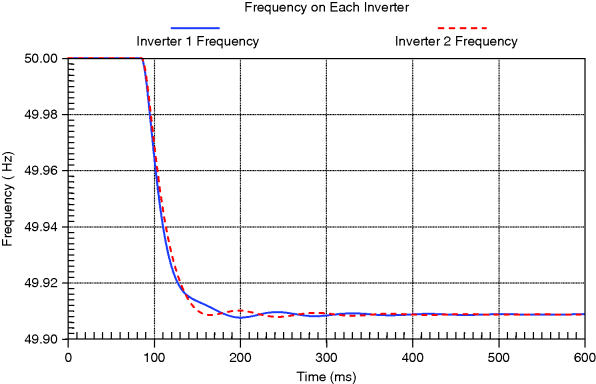
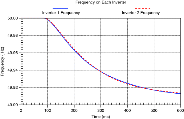
With the fictitious impedance method the stability is easier to reach without the need to fine tune the control parameters. All simulations have been done with 1.4 Ω fictitious reactance. The cut-off frequency of the current low-pass filter is set at 5 Hz and the cut-off frequency of the power low-pass filter is 1 Hz. Simulations have been done with different coupling reactances and the system proved stable in all cases. The system is stable even when the coupling between the inverters is purely reactive, and there is no resistance to damp the oscillations, provided that the fictitious impedance includes a resistive part. In Figure 3.21, it can be seen that the system response is slower than in the previous cases. Figure 3.22 illustrates the inverters frequency response; it is clear that the system frequency now moves gradually to the new balance point.
Figure 3.21 Output power of each inverter with inductive coupling and fictitious impedance method
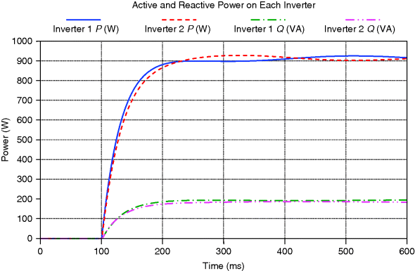
Figure 3.22 Output frequency of each inverter with inductive coupling and fictitious impedance method
3.5.2.2 Resistive Coupling
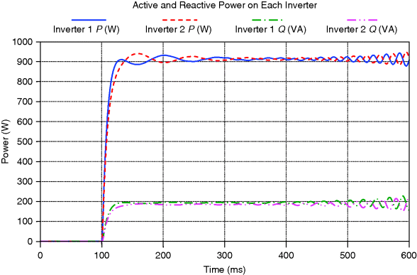
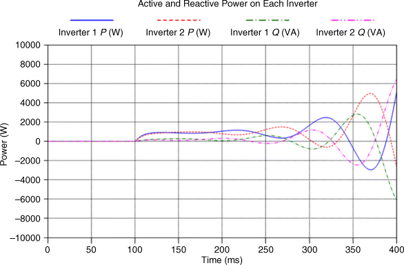
The resistive coupling poses a big problem for the control of the parallel inverter units. In the following simulations each inverter is considered to be coupled with a resistance with value varying from 0 to 0.8 Ω, which means 0% to more than 5% of the characteristic impedance of the devices. When the traditional droop control is applied, stability is very difficult to reach and the system becomes unstable due to the cross-coupling of the control variables (Figure 3.23).
Figure 3.23 Output power of each inverter with resistive coupling and traditional drop control
The use of the fictitious impedance helps to achieve stability in almost all of the cases. With no coupling impedance at all – that is, only with the device output impedance – the system is stable. When the coupling resistance is small the system remains stable, as shown in Figure 3.24, where the behavior of the system with coupling resistances of 0.1 Ω and 0.0 Ω, is shown.
Figure 3.24 Output power of each inverter with resistive coupling and fictitious impedance method, with small resistance
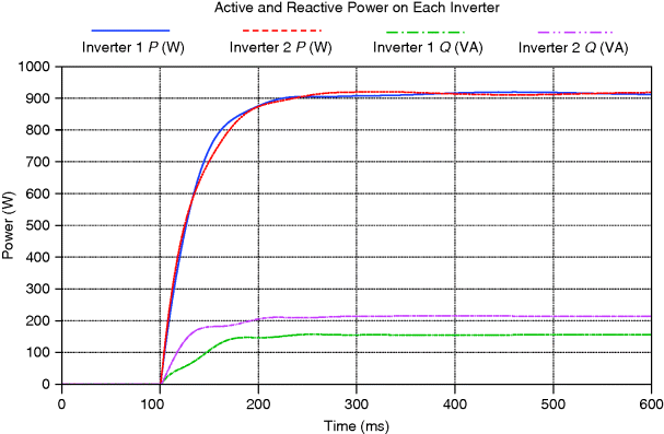
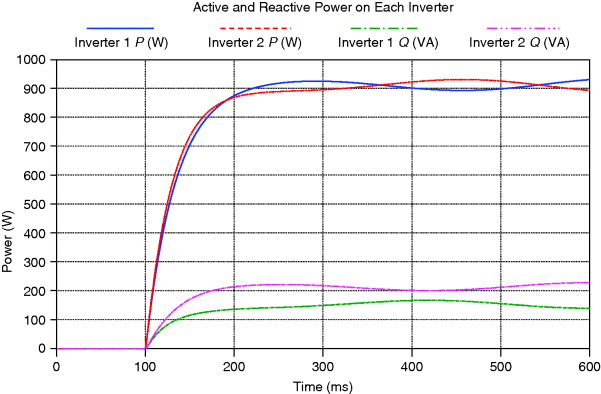
If the coupling resistance is increased, to 0.3 Ω and 0.4 Ω, oscillations take more time to be damped, but the system is still stable. However, when the coupling resistance is increased to 0.7 and 0.8 Ω, the system becomes unstable (Figure 3.25). The problem can be solved by accounting for the coupling resistance in the formation of the fictitious impedance. A reduction of the resistance in the fictitious impedance used can lead to a stable system in all cases. This remaining resistive portion has to be high enough to guarantee the stability in all the inductive cases as well.
Figure 3.25 Output power of each inverter with resistive coupling and fictitious impedance method, with high resistance
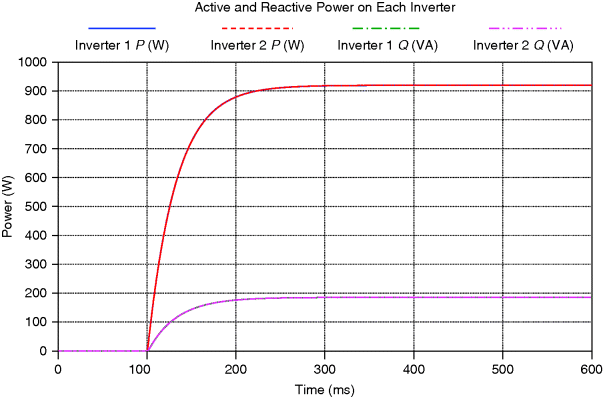
In a more systematic way, we could subtract from the fictitious impedance a resistance value as much as the coupling resistance is expected to be, so that the system will behave overall – including the coupling resistance – only with its fictitious resistance that is specified in the device parameter set. In Figure 3.26, the behavior of the system is shown when the coupling resistance (0.7 and 0.8 Ω) is subtracted from the fictitious impedance. Both inverters work identically, because both have the same parameters and the same output impedance. The problem with this approach, however, is the practical difficulty of estimating the coupling impedance of each inverter, the value of which in more complicated grid configurations may not be clear.
Figure 3.26 Output power of each inverter with resistive coupling and fictitious impedance method, with high resistance and compensated
3.5.2.3 Optimal Reactive Power Sharing
In this case, the optimization of the system performance is addressed by sharing the reactive power among the sources properly. Analyzing all the possibilities, the worst system behavior occurs when the coupling is resistive and the difference between the connection resistances is significant. In these cases, the reactive power is generated mostly by the inverter with the smaller coupling resistance.
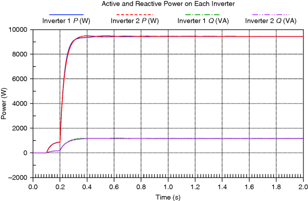
The simulated microgrid consists of two similar inverters with a difference between the coupling resistances equal to 0.4 Ω. Figure 3.27 displays the behavior of the system when the fictitious impedance is 1.4 Ω. It can be seen that while the active power is equally shared, the reactive power is mainly generated by the inverter with the smaller coupling resistance. This behavior is only dependent on the connection impedance and the fictitious impedance. The difference between the two reactive powers increases when the fictitious impedance decreases. The reactive power productions are balanced when the voltage drop provoked by the active power across the extra resistance is equal to the voltage drop created by the difference of the reactive power across the fictitious impedance. This difference can be used by a central controller to estimate the coupling resistances of each inverter, or at least the difference between the inverter resistances. Figure 3.28 shows the performance of the system when the coupling resistance is compensated.
Figure 3.27 Output power of each inverter with unequal resistive coupling and 1.4 Ω fictitious impedance
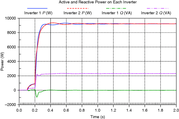
Figure 3.28 Output power of each inverter with unequal resistive coupling and 1.4 Ω fictitious impedance compensated
3.5.3 Stability in Interconnected Operation
In this section the progressive connection of different power sources, the synchronization process of the microgrid with the main grid and the subsequent reconnection and disconnection are studied from the point of view of system stability, proposing improvements in the control strategies.
3.5.3.1 Progressive Connection of Microsources
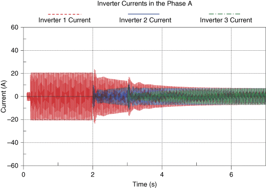
At time t = 0.1 s, a first inverter is connected to a 2 kW load. The load initially has no voltage, so the inverter energizes the microgrid. At time t = 0.2 s, the load is increased to 10 kW. After 2 seconds, when the system has stabilized, a second inverter is connected to the network and the connection of a third inverter follows one second later. All inverters are similar, but a slight difference in their parameters is assumed, in order to study stability issues. It is assumed that each inverter, before connecting to the existing network, has synchronized its output voltage reference (magnitude and phase). The behavior of the system, as expressed by the output power of the three inverters is shown in Figure 3.29 and the inverter currents in Figure 3.30.
Figure 3.29 Output power of the inverters during their progressive connection
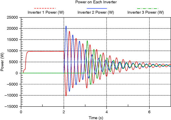
Figure 3.30 Output currents of the inverters during their progressive connection
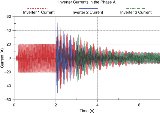
It can be seen that when a new inverter is connected to the microgrid, currents and powers flow from one inverter to the other, until the system reaches equilibrium. One reason for causing fluctuations is that when a new inverter is synchronized, its voltage angle is the same as the angle of the grid voltage, but the frequency is imposed by the power measurement (because of the P/f droop). If the two frequencies are not the same, the inverter frequencies fluctuate around the equilibrium point causing current oscillations. If the frequencies are equal at the first instant, the system moves smoothly to the steady state.
Two main alternatives can be considered to reduce oscillations:
- adapt the internal values of the inverter in order to achieve the same frequency of the inverter and the system during connection
- adjust the dynamic characteristics of the control system at the connection time to improve fluctuation damping
For example, it is possible to act on the P/f droop by adding an offset value to the droop characteristic to obtain the same frequency in the two inverters. Initially, and before connecting the new inverter, the grid frequency is calculated and compared with the inverter zero power frequency. The difference is added to the P/f droop curve when the new inverter connects, resulting in 0 kW power at its output. So the system is supplied by the already connected inverters, while the new one is synchronized with the island. The offset is gradually reduced to zero and the system reaches balance smoothly. Figure 3.31 shows the output powers and Figure 3.32 the currents.
Figure 3.31 Output power of the inverters with offset technique during their progressive connection
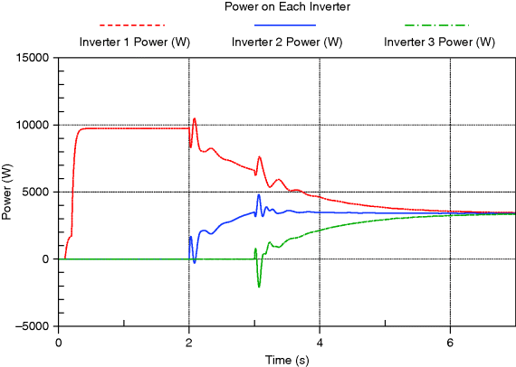
Figure 3.32 Output currents with sudden connection of new inverters using offset technique
The dynamic parameters of the inverters can be changed by temporarily replacing the coupling fictitious impedances and resistances, substituting the cut-off frequencies of the current and power filters, tuning the P/f droop slope or even modifying the digital filter transfer function. It is worth mentioning that the only parameter set that is to be adjusted is the one belonging to the inverter being connected.
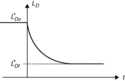
The fictitious impedance can be employed to reduce the transients in power and current by reducing an initial high inductance value ![]() to the final lower value
to the final lower value ![]() with a time constant T ST according to
with a time constant T ST according to ![]() as shown in Figure 3.33.
as shown in Figure 3.33.
Figure 3.33 Progressive reduction of the fictitious inductance from an increased initial value to the final nominal one
3.5.3.2 Transition Between Islanded and Connected Modes
Microgrid transitions from interconnected to islanded mode of operation and vice versa are likely to cause large mismatches between generation and loads, provoking severe frequency and voltage variations.
The problem of microgrid synchronization to the main grid is similar to the previous problem, that is, the angle and the frequency of the two systems must be the same in order to interconnect smoothly, but in this case the solution is more difficult because it requires coordination of all inverter controls. This coordination can be done by an external central controller that guides all the inverters during the synchronization process. One strategy is to communicate an offset value that will be added to the P/f droop characteristic to vary the equilibrium point and modify the frequency. Communication can be continuous and discrete. With continuous communication (wired signal), the synchronization process can be faster and softer, while with discrete communication the offset value is renewed in successive periods of time. In the following simulations the offset value is communicated every half second, but in a real case the communication frequency will affect the synchronization speed.
In the following simulations, three inverters starting from zero at time t = 0 s, form a microgrid. At time t = 1 s, the microgrid reaches steady state and the central controller starts sending offset values. At time t = 5 s, the microgrid is synchronized to the main grid frequency and the breaker closes. A couple of seconds later (t = 7 s) the central controller restores the default offset values. Finally, at time t = 9 s, the microgrid is again disconnected from the main grid.
It should be noted that the inverters always operate as voltage sources, so their control does not need to distinguish between islanded or grid connected mode, where they could operate as current sources. In grid connected mode, at t = 7 s, the central controller changes the P/f droop characteristics to the default value. Taking into account that the inverter operates as voltage source and that network frequency is 50 Hz, the inverter power output goes to zero, allowing the central controller to deliver the desired import/export power through new offset adjustments. If the offset values are applied directly to the P/f curve, as the power output does not change, large frequency oscillations can be observed. To improve this, it is possible to apply the offset indirectly and gradually to the droop curve. If the inverter calculates the power that requires such a frequency shift, in other words, the amount of power that is necessary to vary in order to obtain the frequency shift, and subtracts it from the measured power value, the system will reach the desired frequency more smoothly, as shown in Figure 3.34. Figure 3.35 illustrates the power outputs of the three inverters. Further improvement can be obtained by modifying the low-pass filter parameters, but at the expense of a longer synchronization time (Figures 3.36 and 3.37).
Figure 3.34 Inverter frequencies during transitions from islanded to interconnected mode of operation with indirect offset (t < 5 s, synchronization; t = 5 s, connection to the main grid; t = 7 s, removing of the synchronization offset; t = 9 s, disconnection from the main grid)
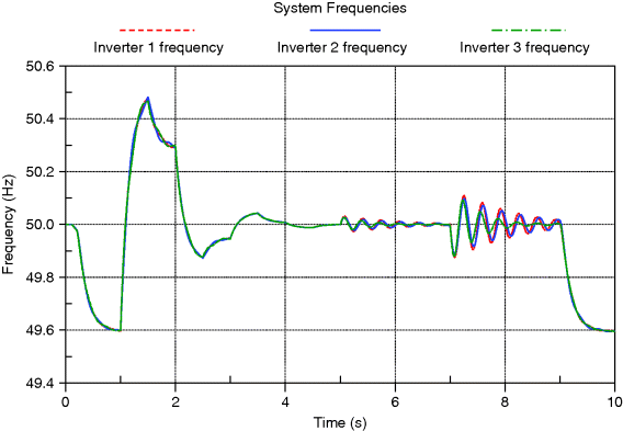
Figure 3.35 Inverter active power during transitions from islanded to interconnected mode of operation with indirect offset
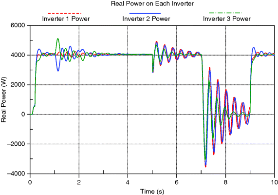
Figure 3.36 Inverter frequencies during transitions from islanded to interconnected mode of operation with indirect offset and modified low-pass filter function
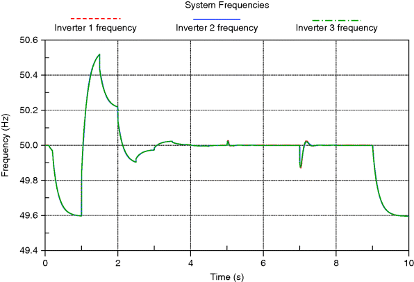
Figure 3.37 Inverter active power during transitions from islanded to interconnected mode of operation with indirect offset and modified low-pass filter function
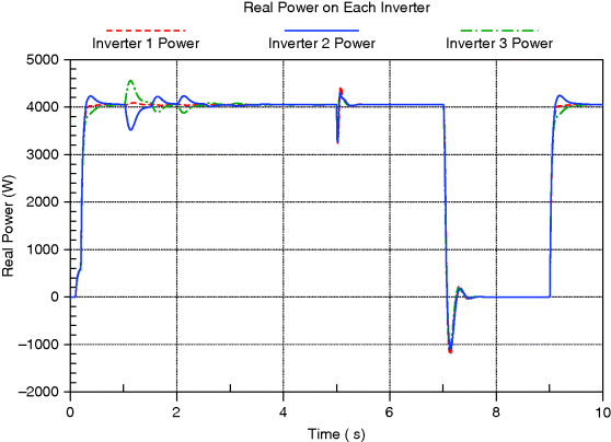
Some power oscillations appear in the connection and disconnection process as the smoothing techniques used in the previous cases are only useful for the individual element reconnection. For a reconnection, in which no communication is used to notify to the inverters their new state, the power measurement low-pass filter can be modified to smooth the oscillations.
3.5.3.3 DER Characteristics
Clearly, not all microsources and storage devices have the same dynamic behavior, and their individual characteristics should be considered. The control algorithm must adapt to the dynamical behavior of the different sources, such as the inherent storage capability or their power change rate, taking advantage of the characteristics of each distributed source (Figure 3.38).
Figure 3.38 Inverter active powers of different sources during sudden load changes
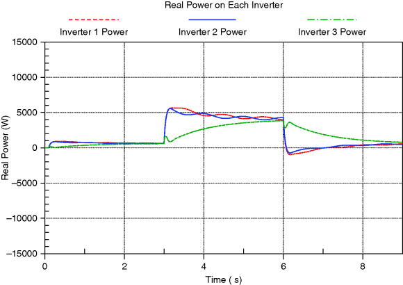
In general, the dynamic response of the inverters is related to their coupling impedances and their transfer functions. The inverter with smaller impedances will react first, while those with larger impedances will take a longer time. The oscillations can be damped by modifying the low-pass filter transfer functions.
3.6 Conclusions
This chapter has outlined the functions of local intelligent controllers of microsources in a microgrid. These controllers are responsible for voltage and frequency control in microgrids and are essential for stable microgrid operation.
Control concepts based on frequency/active power and voltage/reactive power droops as applied on microgrids have been discussed. They are applied to the control of the static converters that usually couple the microgenerators to the network. The feasibility of these concepts is shown by simulations and laboratory investigations. Power sharing in distributed island systems has been shown. The implications of the line parameters on the choice of the droop parameters have been systematically investigated.
Finally, inverter control using fictitious impedance has been analyzed. The fictitious impedance method has proved to be an effective method for controlling voltage source inverters coupled with low reactance, high resistance lines. Reactive power sharing can be improved by compensating the line coupling impedance. Plug-and-play attributes of the control method for different sources have been illustrated.
Overall, it has been demonstrated that microgrids powered by inverter coupled generators can be operated in a stable way. Power sharing and voltage control between spatially distributed generators can be effectively organized within a microgrid by applying intelligent local generator controls which utilize droop control concepts.
1. Chen, J.F. and Chu, C.-L. (1995) Combination voltage-controlled and current-controlled PWM inverters for UPS parallel operation. IEEE Trans. Power Electronics, 10 (5), 547–558.
2. Lasseter, B. (2001) “Microgrids Distributed Power Generation”, IEEE Power Engineering Society Winter Meeting Conference Proceedings, Columbus, Ohio, vol. 1, pp. 146–149.
3. Lasseter, R.H. (2002) “Microgrids”IEEE Power Engineering Society Winter Meeting Conference Proceedings, New York, NY, vol. 1, pp. 305–308.
4. Engler, A. Vorrichtung zum gleichberechtigten Parallelbetrieb von ein- oder drei-phasigen Spannungsquellen, European patent: 1286444 B1 (2006) US patent: 6,693,809 B2 Feb 17, 2004 Japanese patent 2010-1102209.
5. Engler, A., Hardt, C., Strauß, P., and Vandenbergh, M. (October 2001) “Parallel Operation of Generators for Stand-Alone Single Phase Hybrid System”, EPVSEC Conference, Munich.
6. Engler, A. (2002) Regelung von Batteriestromrichtern in Modularen und Erweiterbaren Inselnetzen, Publisher Verlag Dissertation.de, Berlin, ISBN: 3-89825-439-9.
7. Heuck, K. and Dettmann, K.D.Elektrische Energieversorgung, 3rd edn, Vieweg.
8. Burger, B. and Engler, A. (2000) Verfahren und Vorrichtung zur Bestimmung charakteristischer Grössen aus einem zeitlich periodischen Signal, German patent Nr. 199 49 997.7, 15.10.1999.
9. Engler, A. (2005) Applicability of droops in low voltage grids. International Journal of Distributed Energy Resources, 1 (1) 3–15.
10. Chiang, H.C., Yen, C.Y., and Chang, K.T. (2001) A frequency-dependent droop scheme for parallel control of Ups inverters. J. Chin. Inst. Eng., 24 (6), 699–708.
11. Guerrero, J.M., Vasquez, J.C., Matas, J.et al. (2011) Hierarchical control of Droop – Controlled AC and DC microgrids – A general approach towards standardization. IEEE Trans. Indus. Electronics, 58 (1) 158–172.
