CHAPTER 1
Key concepts
Avirtualized network solution built on Windows Server and Microsoft System Center depends on a number of different components. It is important to understand the role these components play in the solution and how they are interconnected, especially if you need to troubleshoot issues with connectivity or have to make changes to your solution to reflect updated business requirements.
This chapter will:
▪ Introduce an example organization
▪ Identify the different components of a virtualized network solution
▪ Provide an overview of each component and how to configure it
▪ Describe how these components are used to configure virtualized networking on multiple Hyper-V host computers
Introducing Contoso Ltd.
Since a lot of planning considerations and best practice approaches are discussed in this book, we’ve use an fictitious organization (Contoso) to help put many of these points into context. Contoso Ltd. is a service provider—otherwise known as a hoster—that offers Infrastructure as Service (IaaS), Platform as a Service (PaaS), and Software as a Service (SaaS) to customers from datacenters located in the United States (Seattle) and the United Kingdom (Reading).
Contoso has more than 1,000 employees worldwide, with the majority of its employees employed in its development and operations center in Reading. Revenues in the last financial year topped £100 million for the first time. Contoso has decided to deploy and use Windows Server 2012 and Microsoft System Center 2012 SP1 for its hosting services moving forward because the company recognizes this platform’s ease of deployment and the cost and efficiency benefits in terms of infrastructure provisioning, infrastructure monitoring, application performance monitoring, automation and self-service, and IT service management.
The chapters that follow discuss the architectural and design decisions that Contoso needs to make to build out the virtualized network component of their new hosting service and provide some best practice recommendations and guidance along the way. Although your organization may not be a service provider and your business requirements may be very different from Contoso’s, the design processes, key decision points, and implications of certain design choices are applicable to all customers that want to use Windows Server and System Center to create a cost effective and highly efficient private or hybrid cloud solution.
Architecture
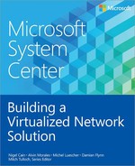
Figure 1-1 is a simplified diagram that illustrates the different layers and components that make up the architecture of a virtualized networking solution based on Windows Server and System Center. In this diagram, the physical network and Hyper-V host computers are at the bottom and the deployed virtual machines and services are at the top. On the right are the names of each component; the labels on the left describe how these components are connected. For example, a logical switch is connected to a logical network via a logical network.
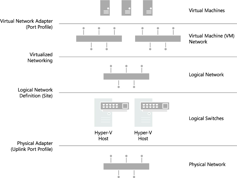
FIGURE 1-1 Architecture of a virtualized network solution.
The sections below provide an overview of each of the major components shown in Figure 1-1 and explain what they are used for and how they connect to other components in the solution. Subsequent chapters will go into more detail and explain how to deploy and use these components within your environment.
Virtualized network components
There are a number of different components in a virtualized network solution that must be defined and configured before you can begin to take full advantage of the features and flexibility provided by Windows Server 2012 Hyper-V and System Center 2012 SP1.
▪ Logical networks These represent an abstraction of the underlying physical network infrastructure and enable you to model the network based on business needs and connectivity requirements.
▪ Uplink port profiles These are applied to physical network adapters as part of logical switch deployment and define the set of logical networks that should be associated with those network adapters. They also specify whether and how multiple network adapters (in a given host computer) using the same uplink port profile should be teamed.
▪ Network adapter port profiles These are templates that define offload settings, bandwidth policies, and security settings for virtual network adapters.
▪ Port classification This is a user friendly label that can be linked to a network adapter port profile. (Port classifications are not shown in Figure 1-1.)
▪ IP address pools These allow VMM to automatically allocate static IP addresses to Windows-based virtual machines that are running on any managed Hyper-V, VMware ESX, or Citrix XenServer host.
▪ MAC Address Pools If virtual machines connected to the logical network will obtain IP addresses from a static IP address pool, you must also configure the virtual machine to use a static MAC address. You can either specify the MAC address manually or have VMM automatically assign a MAC address from a MAC address pool.
▪ Logical switches These bring together uplink port profiles, native port profiles, port classifications, and switch extensions that are relevant to a particular physical or logical network.
▪ Virtual machine networks These provide the network interface through which a virtual machine will connect to a particular logical network.
Logical network
The VMM documentation says that “A logical network is used to organize and simplify network assignments for hosts, virtual machines, and services. As part of logical network creation, you can create network sites to define the VLANs, IP subnets, and IP subnet/VLAN pairs that are associated with the logical network in each physical location.” The documentation goes on to state that logical networks can be used to describe networks with different purposes, to create traffic isolation, and even to support traffic with different types of service-level agreements. You can find more information on logical networks and how to determine how many you need in your environment in Chapter 2, “Logical networks.”
At Contoso, Hyper-V hosts supporting production workloads are situated in two physical locations, Reading and Seattle, with each site using a different VLAN and IP subnet range. Virtual machines running production workloads on hosts in the Reading Datacenter need to use VLAN18 and have an IP address in the 192.168.99.0/24 subnet, where those in Seattle should use VLAN 100 and have IP address in the 192.168.199.0/24 subnet. To allow the Production logical network to be supported in both of these locations, two network sites must be defined as shown in Figure 1-2.

FIGURE 1-2 Defining sites within a logical network.
The Reading network site is scoped to Hyper-V hosts deployed in Reading. It defines the VLAN and IP subnets that will be used by virtual machines that connect to the Production logical network when running on a Hyper-V host in the Reading location. The other network site is scoped to the Seattle host group and essentially defines the VLANs and subnets that will be used by virtual machines deployed in Seattle.
Note that scoping the logical network to a host group in the network site as shown above does not actually make the logical network available on any of the hosts within the group. It simply prevents the logical network from being associated with hosts that are not within the target groups. To make the logical network available on a given host, you need to associate the logical network with a physical network adapter on that host.
At Contoso, READING-VMH2 is one of the servers located in the Reading datacenter. The server is a member of the host group that is authorized for the Production logical network, and since this logical network has been successfully associated with one of the physical network adapters, as shown in Figure 1-3, it can be made available to virtual machines running on that host.

FIGURE 1-3 Logical networks associated with a physical network adapter.
You might expect that the result of this configuration, once it has been deployed to hosts in both locations, would be that a virtual machine connected to the Production logical network can be moved between hosts in Reading and Seattle without requiring any additional configuration. The destination Hyper-V host in the new location ensures that the virtual machine is configured with the VLAN and IP address appropriate for the logical network in the new physical location.
Moving existing virtual machines between sites like this is certainly possible, but there are a few caveats. The main one is that the IP address assigned to the virtual machine will not be changed during migration. If the physical network is a stretched LAN, meaning the same IP subnet is present in both locations, then the virtual machine will continue to communicate on the network once it has been moved. If, as in the earlier example, each site has its own VLAN and IP subnet, then although you will be able to successfully move the virtual machine to a new location, it will have an incorrect VLAN/IP address for that location.
NOTE A virtual machine connected to a virtual machine network that uses Network Virtualization where the Production logical network has been enabled can be moved between hosts in Reading and Seattle without requiring any additional configuration.
IP and MAC address pools
If you associate one or more IP subnets with a network site, you can also create static IP address pools for those subnets. Static IP address pools make it possible for VMM to automatically allocate static IP addresses to Windows-based virtual machines running on any managed Hyper-V, VMware ESX or Citrix XenServer host. VMM can automatically assign static IP addresses from the pool to stand-alone virtual machines and to virtual machines that are deployed as part of a service. It can also assign addresses to physical computers when you use VMM to deploy them as Hyper-V hosts or SMB v3 file servers. When you create a static IP address pool, you can also define a reserved range of IP addresses that can be assigned to load balancers as virtual IP addresses. VMM automatically assigns a virtual IP address to a load balancer during the deployment of a load-balanced service tier. If you define the IP address inside the virtual machine manually, VMM will detect the IP address and the pool to which it belongs (if defined) at the next refresh cycle. This process helps to ensure that VMM does not assign the selected IP address to another virtual machine.
NOTE When isolating network traffic using Network Virtualization, which is covered in more detail in Chapter 2, the logical network also has a relationship with deployed virtual machines in that each machine must be allocated an IP address from one of the IP pools that have been defined for that logical network. An IP address from this pool, otherwise known as provider address (PA), is routable between Hyper-V hosts.
If you configure a virtual machine to obtain its IP address from a static IP address pool, you must also configure the virtual machine to use a static MAC address. You can either specify the MAC address manually or have VMM automatically assign a MAC address from either a central MAC address pool or one that you have created for a specific network site.
Uplink port profiles
Uplink port profiles are applied to physical network adapters as part of logical switch deployment and define the set of logical networks that should be associated with those network adapters. They also specify whether and how multiple network adapters (in a given host computer) using the same uplink port profile should be teamed.
In most cases, a single uplink port profile will be required for each physical network unless you need to define custom connectivity rules, have multiple physical networks, or wish to restrict logical networks to specific hosts within a given physical location, in which case you will need to create additional uplink port profiles. You can find more details on uplink port profiles as well as a process to help you determine whether you need to create more than one of them in Chapter 3, “Port profiles.”
At Contoso, a number of hosts in Reading and Seattle have been dedicated to Production workloads, and port profiles and logical switches (which are discussed in Chapter 4, “Logical switches”) will be used to ensure the host computers in each location are configured consistently. Assuming that the servers in each location have the same type of physical connectivity, only a single uplink port profile should be required.
Figure 1-4 illustrates the network sites that have been configured for the Production uplink port profile. When this uplink is applied to one or more of the network adapters in a Hyper-V host computer in Reading, for example as part of logical switch deployment, it will associate those network adapters with the Production logical network and will also automatically configure the adapter with the VLANs and subnets (as listed in the Reading Production network site) that will be used by virtual machines in that location.
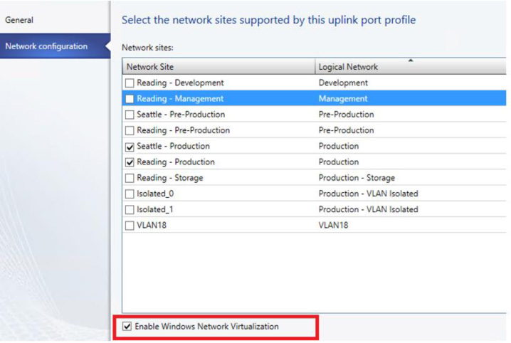
FIGURE 1-4 Defining network sites (and logical network connectivity) in an uplink port profile.
In the example above, multiple network sites are supported by a single uplink profile. When the uplink port profile is applied to a physical network adapter as part of logical switch deployment, VMM checks each network site in the uplink to determine if the host is "in scope" for that site. If it is in scope, , the network adapter will be associated with all of the logical networks that are defined in that network site.
Network adapter port profiles
Network adapter port profiles, which are called native port profiles for virtual network adapters in VMM 2012 SP1 and Hyper-V port profiles for virtual network adapters in the R2 release, are essentially templates that allow you to define offload and security settings for virtual network adapters. Network adapter port profiles allow you to define settings such as virtual machine queue (VMQ), IPsec task offloading, and single root I/O virtualization (SR-IOV) in one place and apply these settings to any virtual network adapter in your environment. You can configure security settings, for example to prevent MAC spoofing, and you can set the bandwidth weight and minimum and maximum possible bandwidth allowed, as illustrated in Figure 1-5.
FIGURE 1-5 Defining bandwidth policy in port profiles.
NOTE Although native port profiles allow you to enable network settings for a virtual network adapter, to be effective some of these (IPsec task offloading, for example) will require additional configuration on the host computer.
Network adapter port profiles and how you can configure and use them are covered in Chapter 3, but to summarize, network adaptor port profiles are used to define the Quality of Service (QoS) settings you want to apply to specific virtual machines and network cards that allow you to take advantage of some of the features provided by your host hardware.
Port classifications
Port classifications are linked to network adapter port profiles. They hide the details, settings, and configuration of a network adapter port profile from the end user. When connecting a virtual machine to the network, end users will see a list of port classifications they can select from, for example "high bandwidth" or "low bandwidth," but they can’t see the priority, bandwidth settings, and IEEE priority value behind a particular configuration. Port classifications are linked to network adapter port profiles and will discussed in Chapter 3.
Logical switches
A logical switch brings together all of the different uplink port profiles, native port profiles, port classifications, and switch extensions that are relevant to a particular physical network. A logical switch is essentially a template that contains an administrator-defined set of parameters you can use to create Hyper-V virtual switches on any of the host computers that connect to the network. When you use a logical switch to create a Hyper-V switch on a host computer, you select the most appropriate combination of port profiles, classifications, and switch extensions from the list of those defined in the logical switch. Generally, a new logical switch is required for every physical network in your environment. But if you plan to restrict some logical networks to a limited set of hosts, as in the example organization in this chapter, or if you have custom connectivity requirements, you may need to create additional logical switches. Chapter 4 covers the design rationale for logical switches.
Given that the example organization has three physical networks (Datacenter, Provider, and Storage) we will need to create at least three logical switches based on the above guidelines. However, only a limited number of hosts in Reading and Seattle will run production workloads that need to be associated with the Production logical network created earlier. The key question is whether an additional logical switch is required to support this environment.
Technically, the Production uplink port profile can be included in the logical switch created for the Datacenter network and the administrator can choose the most appropriate settings and capabilities for the relevant host. VMM can even actively prevent administrators from using any of the Production uplinks when they use the logical switch to create a Hyper-V virtual switch on a host that should not be associated with the Production logical network.
The downside to this approach, however, is that a consistent configuration across hosts in Production is not guaranteed. Although uplink port profiles are restricted to certain hosts, administrators can choose from any of the network adapter port profiles, port classifications, and switch extensions that are available within the selected logical switch. In addition, you may find that capabilities you want offered only on production systems, such as network traffic tagged with IEEE high priority and given maximum bandwidth, are associated with other (non-production) systems because the administrator selected the wrong network adapter port profile during logical switch deployment. To avoid this issue, you should create a separate logical switch for Hyper-V hosts that will support production workloads (see Figure 1-6).
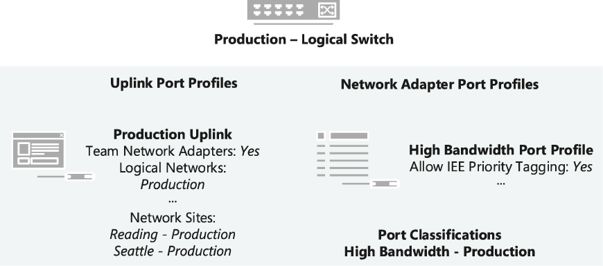
FIGURE 1-6 Contents of the Production logical switch.
As shown in Figure 1-6, the new logical switch will contain the Production uplink port profile and a single network adapter port profile that will ensure that network traffic from these hosts and the virtual machines running on them are tagged with the required IEEE priority flags and are provided with the appropriate bandwidth guarantees. The port classification “High Bandwidth – Production” shown in Figure 1-6 is simply a friendly name for the network adapter port profile and will be displayed to users when they connect their virtual machines to the network.
NOTE The previous example does not include any switch extensions; however, you might want to include these in your logical switch to allow you to monitor network traffic, use quality of service (QoS) to control how network bandwidth is used, enhance the level of security, or otherwise expand the capabilities of a Hyper-V virtual switch created on a host computer. If these enhanced services should be restricted or deployed only on a limited number of hosts, you may need to consider creating an additional logical switch.
MORE INFO You can find more information on Hyper-V virtual switches at http://technet.microsoft.com/library/hh831823.
Virtual machine networks
In terms of overall architecture, virtual machine (VM) networks are the final component to consider in this short overview since they provide the (network) interface through which a virtual machine connects to a particular logical network, as shown in Figure 1-7. You can find more details on VM networks in Chapter 2. Since all virtual machines must be connected to a VM network to be able to use and access network resources in VMM, it follows that you will need at least one VM network for each logical network.
Multiple VM networks can be connected to the same logical network with each one isolated from and totally unaware of the existence of any others. This concept is key to support multiple tenants (clients or customers) with their own networks and will be covered in much more detail in Chapter 6, “Operations.”
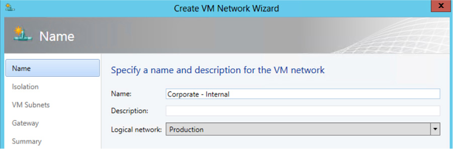
FIGURE 1-7 Mapping a VM network to a logical network.
It is important to note that the relationship between a VM network and its (host) logical network is established when the VM network is initially created and cannot be changed afterward. To use a different logical network, you will need to delete the existing VM network and create a new one.
Deploying the solution
You can of course configure the network settings and properties on each Hyper-V host manually or by using Windows PowerShell, but to ensure consistency and simplify management across multiple hosts it is far more efficient to define the required properties and capabilities within port profiles and logical switches using VMM as described. When a logical switch is applied to a network adapter in a Hyper-V host, VMM uses the information contained in the logical switch and the selected uplink port profile to create a Hyper-V virtual switch on the host and associate the network adapter with the required logical networks, VLAN, and IP subnets. It therefore follows that the host must be a member of a VMM host group that has been scoped to those logical networks. If the host is not in an appropriate host group, deployment of the switch will fail with an Out Of Scope error.
NOTE If you apply the same logical switch and uplink port profile to two or more adapters, the two adapters will be teamed, assuming that this option has been defined in the logical switch. The option to add or remove adapters will be available only if Uplink Mode has been set to Team.
Returning to the example organization, imagine a number of new Hyper-V hosts have been deployed in the Reading datacenter in response to increasing demand for computing capacity in production. Each one of these hosts must be configured for production workloads, meaning that its physical network adapters are teamed to provide maximum bandwidth and a degree of resilience to adapter failure.
Figure 1-8 shows the logical switch being applied on one of the new servers. The administrator has selected the Production uplink port profile to ensure that the selected network adapters are configured with the VLAN and IP Subnets that are appropriate for this location.

FIGURE 1-8 Deploying a logical switch on a Hyper-V host.
Using this information, VMM will create a Hyper-V virtual switch on the host and use the logical networks, VLAN, and IP subnets from the uplink port profile to configure these properties on the selected network adapters. Once the switch has been deployed, the physical network adapter can no longer be configured through the UI or PowerShell; any further changes to the logical networks, VLAN, and IP subnets for the network adapter must be configured in the uplink port profile.
NOTE A Hyper-V virtual switch deployed by VMM can be configured directly on the host computer using native Hyper-V and built-in operating system tools. However making changes to the switch in this way is strongly discouraged since it can lead to unexpected results.