CHAPTER 2
Logical networks
Logical networks represent an abstraction of the underlying physical network infrastructure and enable you to model the network based on business needs and connectivity properties. The Microsoft System Center 2012 Virtual Machine Manager (VMM) documentation indicates that “A logical network is used to organize and simplify network assignments for hosts, virtual machines, and services. As part of logical network creation, you can create network sites to define the virtual local area networks (VLANs), IP subnets, and IP subnet/VLAN pairs that are associated with the logical network in each physical location.” It goes on to state that logical networks can be used to describe networks with different purposes, create traffic isolation, and even support traffic with different types of service-level agreements.
This chapter will:
▪ Identify where logical networks fit into a virtualized network solution
▪ Determine how and why logical networks are created automatically
▪ Introduce a step-by-step process for logical network design
▪ Consider how to optimize design to support network traffic isolation
▪ Discuss the use of network sites, IP, and MAC address pools
▪ Try to help answer the question “How many logical networks do I really need?”
Reviewing key concepts
To help set context for this discussion, begin by referring to Figure 1-1 in Chapter 1, "Key concepts." This diagram illustrates the different layers that make up the architecture of a virtualized networking solution, highlighting logical networks and their connections to other components of the architecture. The key takeaways from this diagram for Chapter 2 are:
▪ Logical networks are connected to a logical switch via a logical network definition (otherwise known as a network site) and to virtual machine (VM) networks via virtualized networking.
▪ VM networks provide the network interface through which a VM connects to a particular logical network.
In addition, since all virtual machines must be connected to a VM network to access network resources in VMM, it follows that you will need to define at least one VM network for each logical network that will be accessed by virtual machines.
Although not shown in Figure 1-1, logical networks also have a relationship with clouds. VMM uses this relationship to scope or otherwise restrict the list of VM networks that are available to users during virtual machine placement. To be placed in a cloud, the virtual machine must be connected to a VM network that is linked to a logical network associated with that cloud. Chapter 6, "Operations," will examine this relationship and how it is used.
Getting started with logical networks
At least one logical network must be associated with a given host computer for it to support deployed virtual machines and services. To help ensure this is the case, VMM verifies that physical network adapters on all new host computers are associated with one or more logical networks. If no such association exists, VMM checks to see if a logical network exists with the same name as the first DNS suffix label on each network adapter. For example, in the case of a server called REA-HST-01.Corp.contoso.com, VMM would expect to find a pre-created logical network called Corp. If it does find a match, VMM will automatically associate the host network adapter with the selected logical network. If it does not, VMM will create a new logical network with that name (Corp) and make the necessary association with the host.
IMPORTANT If the new host computer is connected to a number of different physical networks, VMM could potentially create a new logical network for every physical network the host is connected to.
In a test or proof-of-concept environment, this type of behavior is perfectly acceptable since you want to get up and running as quickly and easily as possible. If you follow the guidance in this rest of this chapter, however, you will have carefully planned and structured your environment and will want to purposely associate a host with the required logical networks rather than rely on any default behaviors. Therefore, turning off this setting is recommended (as in Figure 2-1). The same is true of the option to automatically create virtual switches, which is discussed later in this chapter.
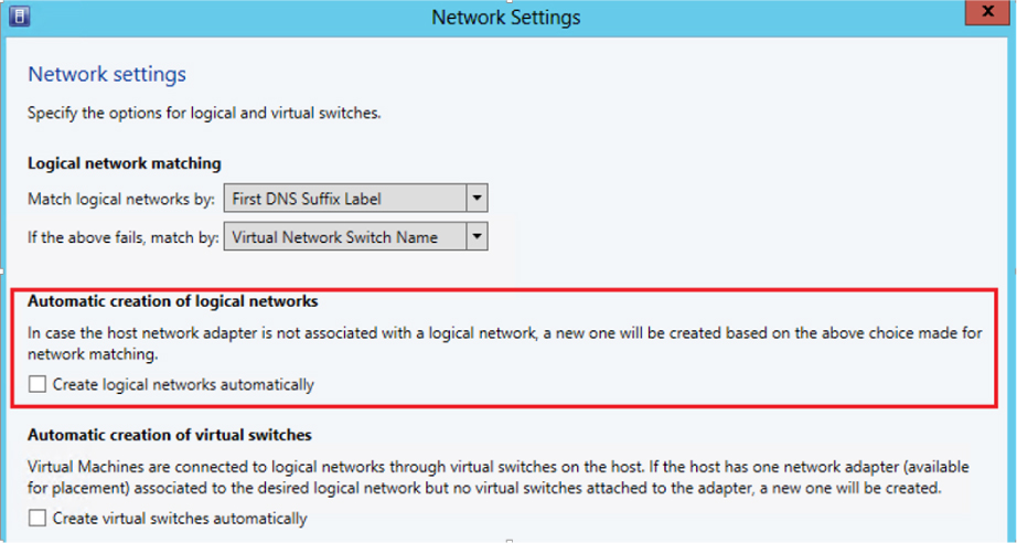
FIGURE 2-1 Turning off automatic logical network creation.
If you leave this setting on initially, you can turn it off later, but be aware that VMM will not allow you to delete any default logical networks that have existing associations with network adapters in your host computers. You will need to associate these adapters with different logical networks first. You may also have to remove VM networks and any other objects that have dependencies on these logical networks before you can successfully delete them.
Logical network design
The goal in this chapter is to present a step-by-step approach to logical network design, starting from the basic principle that you should begin as simple as possible and then add additional logical networks only where there is a compelling business or technical reason to do so. The process can be summarized as follows:
1. First, define a set of logical networks that initially mirror the physical networks in your environment.
2. Define networks that have a specific purpose or perform a particular function within your environment.
3. Identify which logical networks need to be isolated and how that isolation will be enforced, either through physical separation, VLAN/PVLAN, or Network Virtualization.
4. Determine the network sites, VLANs, PVLANs, and IP pools that need to be defined for each logical network you have identified.
5. Finally, associate the logical network with the host computers that will support it (you will find details for doing so in Chapter 5, “Deployment”).
As usual, defining and adhering to a sound naming convention for logical networks is important both to promote understanding and to help simplify management and reduce cost.
Introducing the Contoso network
To set this process in context, take a closer look at the physical network in the example service provider, Contoso Ltd., and identify the set of logical networks that will be needed to support this company’s specific business requirements. Although your own network layout and business requirements might be different from Contoso’s, the design process, key decision points, and the implications of certain design choices are applicable in all cases.
As shown in Figure 2-2, Contoso has three physical networks in each of its datacenters:
▪ Corporate (internal) workloads and services are hosted on the Datacenter network.
▪ Customer (tenant) network traffic is on the Provider network.
▪ Storage devices are accessed via the Storage network.
The physical separation between customer, storage, and corporate network traffic improves security, simplifies infrastructure management, and removes potential competition between different types of network traffic.
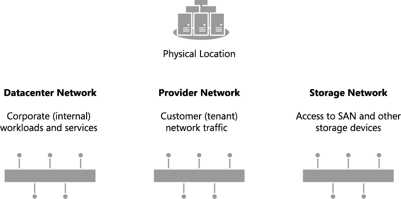
FIGURE 2-2 Physical networks in each Contoso datacenter.
The following sections outline the five step logical network design process for Contoso, identifying the set of logical networks the company needs to support its business and technical requirements and highlighting some of the key decision points and best practice recommendations along the way.
Step 1: Mirror physical networks
It seems reasonable to begin by creating logical networks that map to and mirror each of the physical networks in the environment, but you should expect to create many more logical networks than you have physical networks. Indeed, one of the key benefits of logical networks is that they provide flexibility, allowing you to separate computers and network services with different business purposes, isolate network traffic, or support different workloads with network service levels, all without having to change the physical network infrastructure. With that said, creating one logical network for each physical network is a very useful beginning.
Since Contoso has three physical networks (Datacenter, Provider, and Storage), the assumption is that that three logical networks will be required to support this environment, one for each physical network, as shown in Figure 2-3. As you will discover in the sections that follow, you will likely need to create additional logical networks to support specific business and technical requirements. But as a guiding principle, you should always start with as simple a design as possible, adding logical networks only where there is a clear and justifiable reason for doing so.

FIGURE 2-3 Logical networks that mirror the physical network.
Step 2: Networks with different purposes
It’s a basic assumption that computers and devices that connect to and use the same network should be able to communicate with each other with routers or gateway devices used to connect different networks should this be required. This general principle also holds true for logical networks, so the next step in the design process is to identify the different groups of users, applications, and network services that will use each of the physical networks and determine whether there is a need to separate them to enforce security, ensure privacy (isolation), simplify management and administration, or simply to ensure that network traffic from certain groups is provided with the required Quality of Service (QoS).
Step 1 started with the principle that a single logical network would be sufficient for each of Contoso’s three physical networks, Datacenter, Provider, and Storage. Step 2 reviews each physical network to determine whether this design is appropriate for the groups of computers and network services that will use them.
Datacenter physical network
The Datacenter physical network at Contoso Ltd. carries network traffic generated by corporate (internal) services and applications as well as network traffic needed to support and maintain the cloud fabric (infrastructure services such as host management, live migration, and cluster heartbeat). Step 1 established a single logical network, Datacenter. The question is whether this design is appropriate for the workloads on this network.
CORPORATE (INTERNAL) SERVICES
If development, test, and production network traffic all share the same physical network, you will invariably want to differentiate these workloads. In the example Contoso environment, development, pre-production, and production workloads will coexist on the Datacenter physical network. To make this environment easier to manage, three separate logical networks are created, one for each workload type, as shown in Figure 2-4. Note that network adapter port profiles (explained in Chapter 3, “Port profiles”) will be used to apply the required properties and capabilities, including bandwidth limitations and IEEE priority tags, to virtual machines and services that connect those networks.

FIGURE 2-4 Using logical networks to differentiate workloads.
NOTE If corporate policy mandates that an application or workload can be hosted only on a particular group of host computers, you would start by defining a separate logical network and then using Host Groups and Network Sites to ensure that it is only associated with the selected host computers.
The VMM documentation suggests that you also consider creating separate logical networks for the front end (web servers) and the back end components (application and database servers) of multi-tier applications. The primary benefit of such an approach is that it allows you to use network sites to define the set of VLANs and IP subnets that will be used by virtual machines in each tier and, further, to apply a different set of security settings and capabilities to each network through the use of port profiles.
Since Contoso is expecting to deploy and use multi-tier applications, the logical network design for internal (corporate) workloads needs to be refined with the creation of separate logical networks for the front end and back end components of these services, as shown in Figure 2-5. Note that production workloads that are not part of any multi-tier application will be expected to connect to and make use of the Back End logical network.
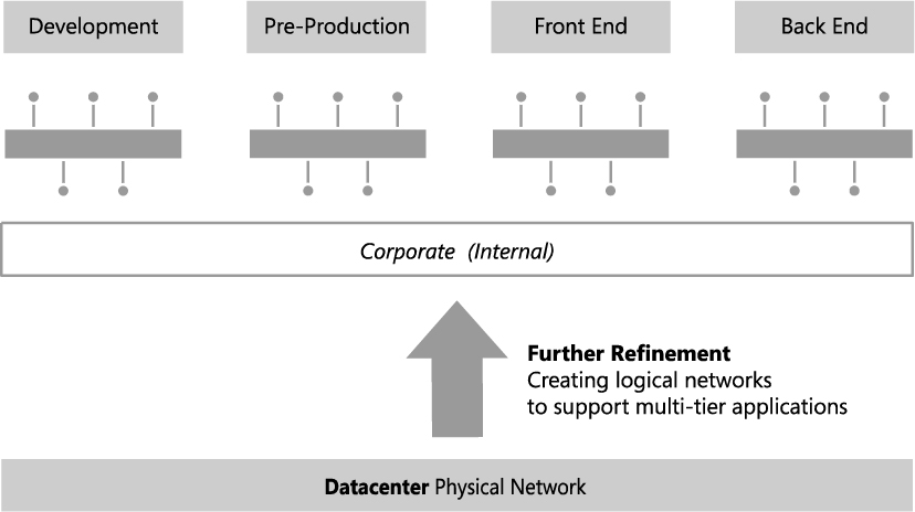
FIGURE 2-5 Dividing Production into front end and back end logical networks.
Traffic prioritization, network bandwidth control, and support for multi-tier applications are just a few of the reasons why you might consider creating logical networks for corporate (internal) workloads. Security concerns, the requirement to isolate certain workloads, and the need to restrict the host computers on which a given business service can run are also key considerations. Consider each case on its merits, reviewing the business case as well the technical requirements, with the aim of creating logical networks only when really necessary and keeping the design as simple and as easy to understand as possible.
CLOUD INFRASTRUCTURE
As mentioned earlier, Contoso network traffic for cloud infrastructure (fabric) management will be on the same physical datacenter network as corporate workloads and will probably require a separate logical network to differentiate this traffic from anything else on the network. There are a number of different types of cloud infrastructure traffic, including CSV, backup operations, live migration, hardware management, and host/guest management. Will a single logical network suffice for all of these operations or will it be necessary to create logical networks for each type of infrastructure traffic?
In keeping with the guiding principle to create logical networks only when necessary, the key decision point is whether to apply different capabilities, bandwidth controls, and network traffic prioritization to each one of these services. If the answer is no, then a single logical network will suffice. If the answer is yes for a limited number of these services (backup and live migration are normally good candidates), then a dedicated logical network for those services should be created, with the remainder using a shared infrastructure logical network.
Contoso has chosen to create logical networks for each of the infrastructure services, as shown in Figure 2-6. You might choose to implement this differently, adding or removing logical networks from the design based upon your requirements and the capabilities of your network infrastructure.
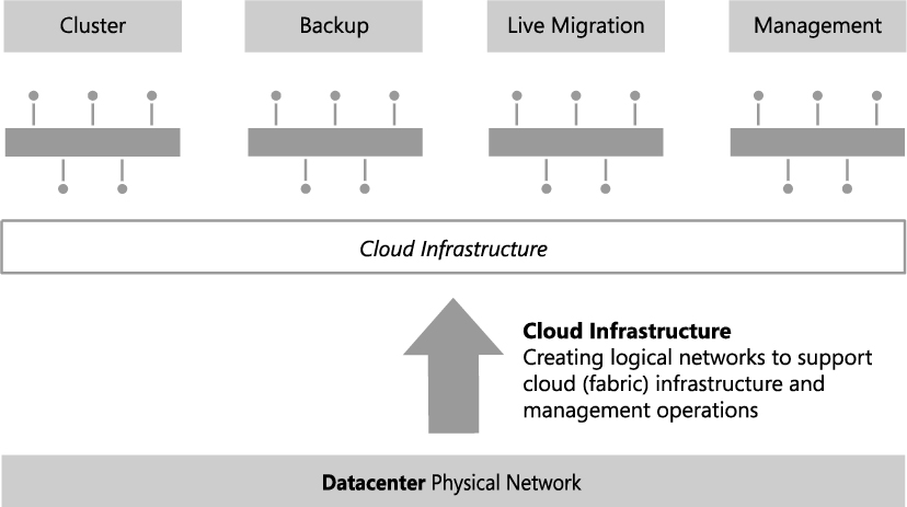
FIGURE 2-6 Using logical networks to differentiate cloud infrastructure services.
Provider physical network
Contoso is a service provider (hoster) and offers hosted software and services, including web hosting, application hosting, messaging, collaboration, and platform infrastructure, to its end customers. The Provider network is dedicated to and used exclusively for customer (tenant) network traffic. The physical separation between customer network traffic on the Provider network and internal traffic on the Datacenter physical network improves security, simplifies management, and, additionally, removes any potential competition between customer and corporate (internal) workloads.
MORE INFO Some organizations are primarily service providers and others are enterprise customers who provide hosted software and services internally or externally to their customers or business partners. Planning to separate internal or cloud infrastructure and customer (tenant) workloads is relevant to both types of organization. You can find more details at http://technet.microsoft.com/en-us/library/hh831441.aspx.
In designing a logical network solution for a provider network such as the one at Contoso, you should first consider the compute models the organization intends to support. Essentially this means determining whether workloads from multiple customers will run on the same physical hardware (shared compute), if certain host computers and resources will be dedicated to a single customer (dedicated compute), or if you will support both of these scenarios. A good starting point for the design is a single logical network for the shared compute workloads and a separate logical network for each customer that uses dedicated resources.
For customers with dedicated resources, host groups and network sites in VMM will associate the logical network with the host computers within each physical location that has been allocated to ( reserved for) that customer. This is covered in much more detail in Chapter 5, “Deployment.”
Contoso, like many service providers, allows customers to choose which of these approaches works best for them. Customer workloads may be hosted on either shared or dedicated resources, with the latter attracting a price premium. Two customers have opted for physical servers dedicated to their workloads, with the remainder utilizing the shared compute model. The logical network design to support this model of operation (ignoring isolation) is shown in Figure 2-7. The design assumes that as new customers with dedicated compute requirements are onboarded to the service, additional logical networks will be added to the solution.
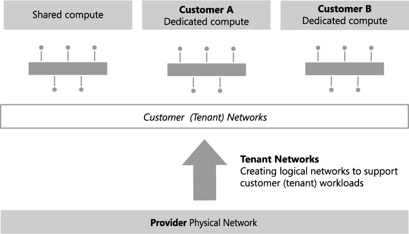
FIGURE 2-7 Logical networks for a mixed shared and dedicated compute model.
In reality and as discussed for the Datacenter network, you may need to extend this initial model, breaking out (defining) additional logical networks to support a specific hosted service or to support a specific business or customer requirement.
Storage physical network
The final physical network for Contoso is dedicated to a single purpose: providing access to shared storage. A single logical network that maps directly to the physical network (as initially conceived in Step 1 of this process) is therefore quite appropriate. Note that if Contoso were to use multiple IP-based storage technologies (such as iSCSI and SMB) on the physical network, each of these technologies would likely be allocated its own logical network.
Step 3: Determine isolation requirements
At the end of Step 2, you should have arrived at a set of candidate logical networks for each physical network in your environment. The next step is to review the isolation requirements for each logical network you have identified so far, something which is clearly an important consideration for service providers hosting external customer workloads and enterprise customers needing to isolate network traffic from certain business groups or restricted (special) projects. These security requirements may lead you to create additional logical networks or at least further refine your logical network design.
To understand this concept, consider the basic assumption stated earlier: computers that connect to and use the same network should be able to communicate with each other through routers that connect different networks together, enabling inter-network communication. This principle holds in most cases. Indeed, where there is a business need to split off or otherwise isolate certain workloads for security, to improve performance, or simply to facilitate more effective control of network traffic, the best solution is to create a new network, either physically or via virtual networks (VLAN or PVLAN technology), place all of the appropriate computers and services on that network, and update the network routing tables and security policy to facilitate inter-network communication. This approach will be familiar to both enterprise customers and service providers, with the latter often using dedicated VLANs and PVLANs to isolate different customers from one another.
Historically, logical networks in VMM effectively modeled this behavior by enabling resources connected to a given logical network to communicate with any other resource on that same network, with inter-network communication handled via a router or gateway device. The problem with this solution for service providers (hosters) was that each customer invariably required a distinct logical network, which led to the creation of hundreds if not thousands of logical networks within VMM, resulting in performance issues and increased complexity and management overhead.
VM networks were introduced to address this particular issue. Rather than connecting directly to a logical network, VMs in this release connect to a VM network, which acts as an interface to a particular part of a logical network, as shown in Figure 2-8. Since VM networks are linked to the logical network instead of associated with physical host computers, adding, deleting, and making changes to these VM networks is easier than making changes to logical networks. Multiple VM networks may be linked to each logical network, removing the need for service providers to create separate logical networks for each of their customers.
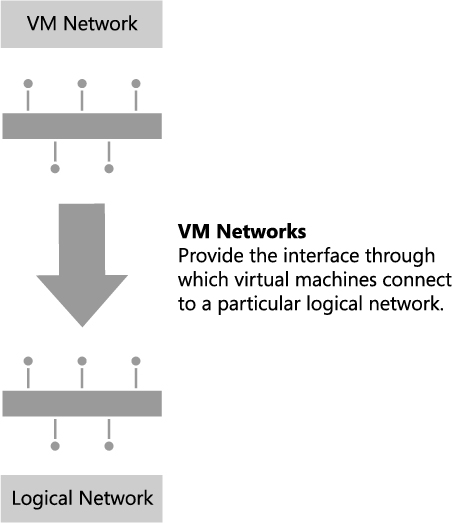
FIGURE 2-8 VM networks’ relationship to logical networks.
If there is no need to separate or otherwise isolate network traffic from certain machines, only a single VM network linked to the logical network is required. As described earlier, multiple VM networks are required to host workloads for multiple customers (tenants) on the same logical network, with each tenant isolated from and unaware of any others.
In VMM, you can isolate VM networks by using either traditional VLAN (or isolated PVLAN) solutions or, if you are using Windows Server 2012 as your host operating system, by implementing Network Virtualization. The latter option addresses the scale limitations associated with a traditional VLAN solution and allows tenants to “bring their own network” or otherwise extend their network into your environment.
MORE INFO The different ways that VMM can isolate network traffic are well illustrated by the Logical Networks section of the "Networking in Virtual Machine Manager" poster that can be downloaded from the Microsoft Download Center at http://www.microsoft.com/en-us/download/details.aspx?id=37137.
Note that you cannot mix and match different types of network isolation on the same logical network. It’s impossible, for example, to isolate some VM networks by using VLAN/PVLAN technology and others by using Network Virtualization. Should you need to use multiple approaches in your environment, you will need to return to Step 2 above and create a separate logical network for each isolation method.
MORE INFO There is a practical limit of approximately 2,000 tenants and 4,000 VM networks per VMM server. If you expect to approach either of these scale limitations you will most likely need to introduce additional VMM servers and use Service Provider Foundation to manage this environment. You should follow the same process described in this section to identify and create logical and VM networks for each VMM server you deploy. You can find more information on Service Provider Foundation at http://technet.microsoft.com/en-us/library/jj642895.aspx.
No isolation
Isolation is necessary only in cases where a logical network will be used by multiple customers (tenants). Logical networks created for corporate (internal) workloads, cloud infrastructure services, and logical networks that are dedicated to a specific customer are all single tenant, meaning that traffic isolation is optional.
As mentioned earlier, at least one VM network is required for logical networks that will be accessed by VMs. If there is no need to isolate network traffic on the logical network, only a single VM network configured for No Isolation, as shown in Figure 2-9, is required. The VM network in this example simply acts as a “pass through” to the logical network.
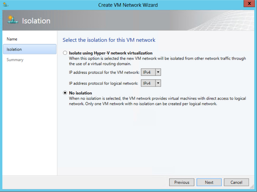
FIGURE 2-9 Creating a VM network with no isolation.
NOTE In VMM 2012, virtual machines were directly connected to logical networks. When customers using this release upgraded to SP1, VM networks configured for No Isolation were automatically created for each of these logical networks. Virtual machines that existed prior to the upgrade were then connected to the new VM network linked to their original logical network.
This configuration establishes a one-to-one mapping between the VM network and the logical network, as shown in Figure 2-10. As a result, only one VM network per logical network can be configured for No Isolation. If virtual machines that connect to this VM network should be restricted from communicating with each other, you may need to consider breaking out an additional logical network to accommodate this requirement.
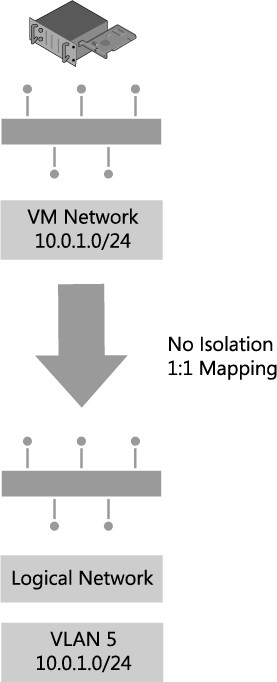
FIGURE 2-10 VM network direct access to the logical network.
NOTE For logical networks that will not be used by virtual machines, generally those dedicated to infrastructure services like storage and live migration, you may not need to create VM networks at all.
VLAN isolation
As discussed earlier, VMs in VMM connect to a VM network which acts as an interface to a particular logical network. Multiple VM networks may be linked to the same logical network if Network Virtualization is enabled, with each one of these VM networks separated from and unaware of any of the others. These improvements mean that instead of creating a separate logical network for each customer that will be isolated from others using VLAN technology, you can instead create a single logical network for all of these customers, configuring the properties of the network, as shown in Figure 2-11, to specify that sites within this logical network are not connected. Each VM can be allocated a friendly name to clearly identify its purpose and which customer has access to it. You can also apply access control to restrict who can use it.

FIGURE 2-11 Configuring a logical network for VLAN isolation.
Each VLAN must be allocated to a network site. Multiple VLANs can exist with the same site, as shown in Figure 2-12, but each one will be totally isolated from any of the others.

FIGURE 2-12 Defining network sites for VLAN isolation.
Finally, VM networks need to be created to allow customer virtual machines to connect to and use the logical network. Each VM network you create is directly mapped to exactly one of the subnet VLANs that have been defined for a site in that logical network. As a result, you can have only as many VM networks as you have subnet VLANs. The Create VM Network Wizard, shown in Figure 2-13, will display only those network sites that have not already been allocated to an existing VM network.

FIGURE 2-13 Allocating a VLAN (network site) to a VM network.
Although you can manually choose which VLAN should be allocated to a VM network, VMM also provides for automatic assignment. This is useful where customers are allocated a VLAN from a pool rather than being given an assigned VLAN. In these cases, a VLAN is randomly assigned from the pool when you define a new VM network and is returned and available for re-use when that VM network is deleted. Note that once all of the available network sites have been allocated, no further VM networks may be linked to this logical network until additional VLANs are added or some of the existing VM networks are deleted.
To briefly summarize, create a single logical network configured with the Sites Within The Logical Network Are Not Connected option, create sites, and then specify the list of VLANs that exist in each site. Either create a VM networks to represent each VLAN or create VM networks as needed using automatic assignment to allocate a network site (VLAN) to that VM network. The net result should be a one-to-one mapping between the VM network and the network site, as shown in Figure 2-14.

FIGURE 2-14 Logical network design for VLAN isolation.
There are a number of limitations to using VLANs to isolate network traffic, most significantly the scalability limits. Only 4,095 VLANs are permitted per physical network. PVLANs may be used to work around this limitation, but at a cost of increased complexity. The cost of management, level of complexity, and the risk of error also increase significantly at high scale. These issues may not be of direct relevance to enterprise customers since, in general, they do not need to manage very large numbers of networks at this scale, but these are major considerations for service providers that provide hosted services to a large number of external customers.
VLAN isolation is expected to remain common practice in many enterprise deployments given its relative simplicity and ease of management at smaller scale. Service providers (hosters), however, can be expected to use alternative isolation technologies to help work around VLAN scale limitations given their need to manage a much larger number of networks.
PVLAN Isolation
Private virtual LANs (PVLANs) are often used by service providers (hosters) to work around the scale limitations of VLANs. They essentially allow network administrators to divide a VLAN into a number of separate and isolated sub-networks which can then be allocated to individual customers (tenants). PVLANs share the IP subnet that was allocated to the parent VLAN, as you might expect, but they require a router to communicate with each other and with resources on any other network.
A PVLAN consists of a primary and secondary VLAN pair. Each machine that is part of a PVLAN pair can be configured in one of three modes as shown in Figure 2-15. In promiscuous mode, hosts are on the primary VLAN and can communicate directly with resources on both the primary and secondary VLANs. In community mode, the secondary VLAN represents a community. Direct communication is permitted only with hosts in the same community and those that are connected to the primary PVLAN in promiscuous mode. In isolated mode, direct communication is permitted only with promiscuous resources on the primary PVLAN.
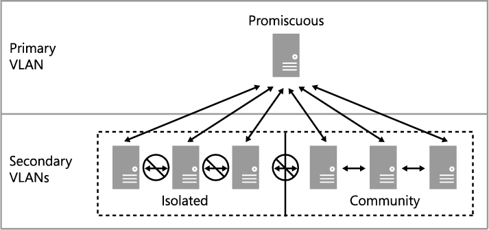
FIGURE 2-15 The three modes for PVLAN isolation.
VMM only supports isolation mode and has no concept of primary (promiscuous) or community modes. What this means in practice is that a virtual machine connected to a PVLAN in this release is completely isolated from any other resources on the network. The only device it can directly communicate with is the default IP gateway. While this may feel like a severe limitation, there are a number of scenarios that work quite well in this configuration, the most common example of which is front end web servers. In this specific scenario, all of the web servers in a web farm are placed on a single network subnet but are otherwise completely isolated from each other, PVLANs in this context, helping to simplify management and improve overall security.
NOTE Similar functionality to community mode can be achieved by adding an additional network adapter to the VM and connecting this adapter to a VM network on which Network Virtualization has been enabled and to which all of the other community resources are also connected.
In terms of logical network design, you should create a single logical network when using PVLANs, configuring the properties of the logical network with the Sites Within This Logical Network Are Not Connected and Network Sites Within This Logical Network Contain Private VLANs options, as shown in Figure 2-16.
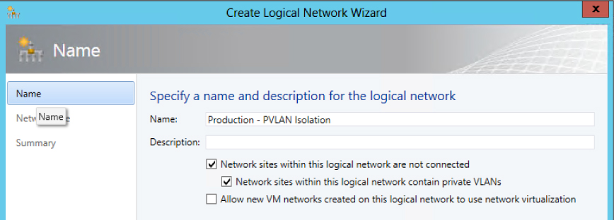
FIGURE 2-16 Enabling PVLAN isolation.
The Network Site page of the Create Logical Network Wizard includes a subtle but important difference for PVLANs. In addition to the primary VLAN, the Associated VLANs And IP Subnets section contains an additional column called Secondary VLAN. You should associate each primary VLAN and secondary PVLAN with a network site within the logical network, as shown in Figure 2-17. You can also define multiple PVLANS in the same network site as needed.

FIGURE 2-17 Network site configured for PVLAN isolation.
Only one PVLAN can be in isolated mode per primary VLAN, and you should take care to ensure that a different primary VLAN ID is used in each network site you create. The ID you use for the PVLAN, however, may be the same in each site. In fact, using the same ID for the isolated PVLAN is actually recommended to ensure consistency and simplify management.
As discussed, VM networks are needed for VMs to connect to and use the logical network. Each VM network you create is directly mapped to exactly one of the PVLANs that have been defined for that logical network. As a result, you can have only as many VM networks as you have defined PVLANs. As shown in Figure 2-18, the Create VM Network Wizard displays only those PVLANs that have not already been allocated to an existing VM network. Note that the wizard does not offer the option for automatic assignment even though the UI suggests that this is possible.
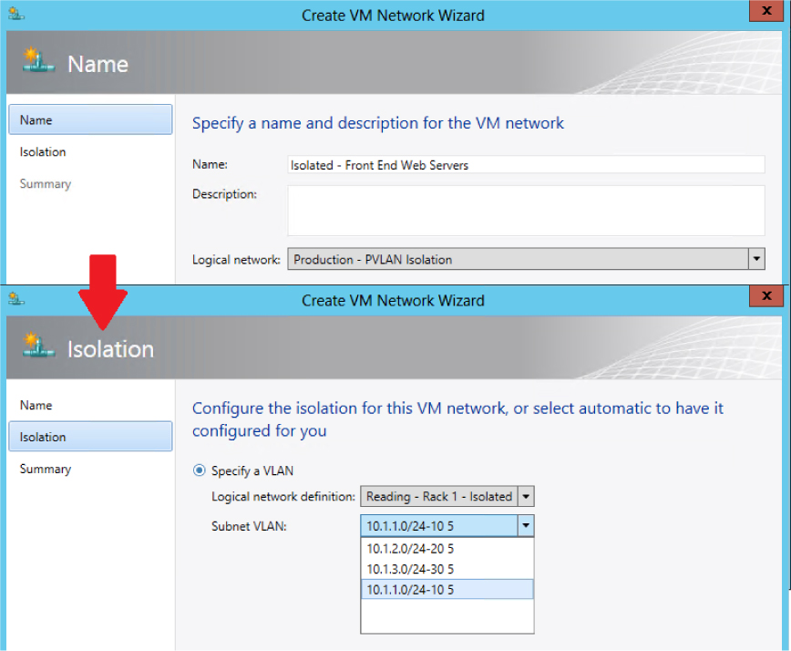
FIGURE 2-18 Allocating a PVLAN (network site) to a VM network.
To briefly summarize, create a single logical network to support PVLAN isolation, then configure it with the options Sites Within The Logical Network Are Not Connected and Network Sites Within The Logical Network Contain Private VLANs. You should create a network site, define primary and secondary VLAN pairs, and create VM networks for each one, as shown in Figure 2-19. In this example, PVLAN 5 is designated as the isolated PVLAN for consistency across all primary VLANs. Your implementation may be different.

FIGURE 2-19 Logical network design for PVLAN isolation.
Although each virtual machine you connect to one of these VM networks will be assigned an IP address from the same subnet, it will be able to communicate only with the default IP gateway or with other network devices in promiscuous mode, but note that devices in promiscuous mode must be set up and configured outside of VMM. If all of the virtual machines are present on the same physical host, isolation will be enforced through the Hyper-V extensible switch. Otherwise you will need to make sure that each of the PVLANs you define in VMM are also configured for isolation mode on the physical switch. To avoid potential IP conflicts with resources that exist on the primary VLAN (and any community VLANs that were created outside of VMM), it is recommended that you reserve a set of IP addresses and create a separate IP pool for each PVLAN. The IP addresses you reserve must be part of the IP subnet that was allocated to the primary VLAN.
Network Virtualization
Network Virtualization provides administrators with the ability to create multiple virtual networks on a shared physical network. In this approach to isolation, each tenant receives a complete virtual network, which includes support for virtual subnets and virtual routing. Tenants can even use their own IP addresses and subnets in these virtual networks, even if these conflict with or overlap with those used by other tenants. Further, since virtual networks are defined entirely in software, it is unnecessary to reconfigure the physical network (unlike VLAN and PVLAN solutions) to onboard or remove tenant networks or to make changes to reflect new business requirements.
NOTE You can find more details on this approach at http://blogs.technet.com/b/windowsserver/archive/2012/08/22/software-defined-networking-enabled-in-windows-server-2012-and-system-center-2012-sp1-virtual-machine-manager.aspx.
In Figure 2-20, Tenant A has two virtual subnets. A virtual router automatically created by Windows Server 2012 Hyper-V connects the two subnets for this tenant and allows VMs on each subnet to communicate with each other. Tenant B has a single virtual subnet but still has its own virtual router. The virtual subnet ID and routing domain ID shown in the diagram are used by Hyper-V host computers to differentiate network traffic and routing for each of the tenants.
NOTE The virtual router does not exist on any one host. It essentially spans all hosts that contain VMs that are part of a particular VM network.
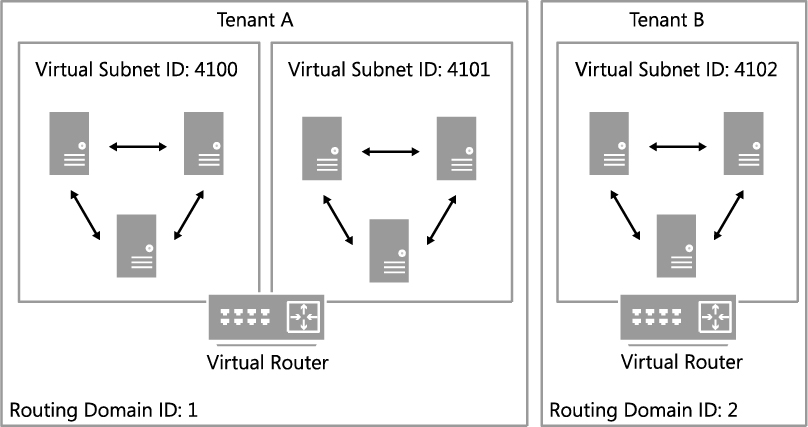
FIGURE 2-20 Logical network design for isolation using Network Virtualization.
When using Network Virtualization, the logical network design is relatively simple: create a single logical network for all of your customers that will be isolated from each other using Network Virtualization and configure the properties of the network with the Allow New VM Networks Created On This Network To Use Network Virtualization option, as shown in Figure 2-21.
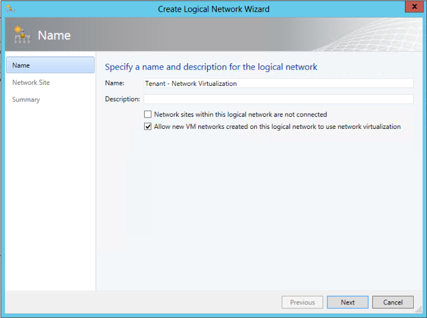
FIGURE 2-21 Configuring a logical network to support Network Virtualization.
You need to create network sites to define the VLANs and IP subnets that are to be associated with the logical network in each physical location. Assuming you specify VLANs in your network sites, the physical network must be able to route network traffic between them. The VLANs in this case are used by the network administrator for ease of management and to control broadcast traffic; they are not used as an isolation mechanism. Note that these VLANs exist on the Hyper-V host server Parent Partition only—tenant VMs are unable to gain access to them.
Note that an IP pool must be associated with every single network site linked to the logical network, as shown in Figure 2-22. The IP addresses from these pools, also known as provider address (PA) pools, must also be routable between all of the Hyper-V hosts associated with the logical network.
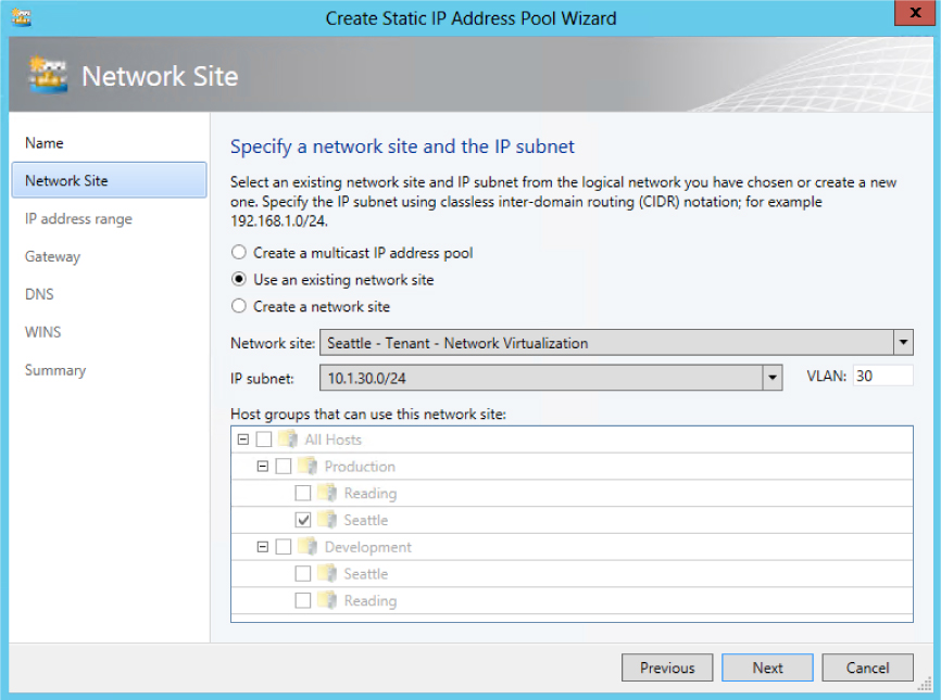
FIGURE 2-22 Defining a provider address IP pool for a network site.
You will also need to create VM networks to allow customer VMs to connect to and use the logical network, and you should define a separate VM network for each tenant, with each one of these VM networks configured to isolate using Hyper-V Network Virtualization, as shown in Figure 2-23. You can also select No Isolation if you want the VM network to provide virtual machines with direct access to the logical network. Note that the option to enable isolation shown in Figure 2-23 is only available when provider address IP pools have been defined for the IP protocol (IPv4 or IPv6) supported by the logical network as mentioned earlier.
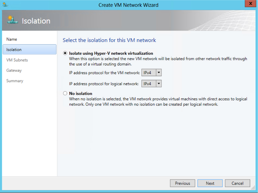
FIGURE 2-23 VM network isolation using Hyper-V Network Virtualization.
You also need to define the IP subnets for each VM network, setting out the IP addresses that will be used by VMs connected to that network, as shown in Figure 2-24. These addresses, known as the Consumer Address (CA), are completely separate from any other tenant and from the logical network. Tenants can therefore use their own IP addresses and subnets in their virtual networks, even if these appear to conflict with or otherwise overlap with those used by other tenants. Again, each tenant may be allocated multiple subnets, as shown in Figure 2-24.
NOTE VMM installs a DHCP Virtual Switch extension on each host that it manages. If a tenant’s VM uses DHCP to request an IP address, the extension will respond by offering an IP address from the IP pool that has been defined for the VM network.

FIGURE 2-24 Defining consumer IP subnets.
To briefly summarize, create a single logical network for tenants that are to be isolated using Network Virtualization, configured with the option Allow New VM Networks Created On This Network To Use Network Virtualization, and define network sites and IP pools for each location in which the network will be supported. You should then create VM networks for each tenant. The result should be a one-to-many mapping between the logical network and VM networks created to support each tenant, as shown in Figure 2-25.
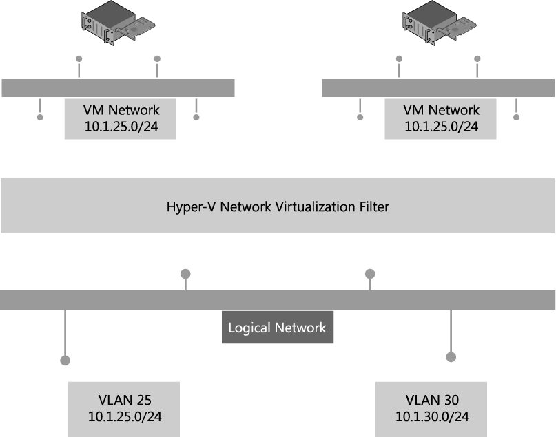
FIGURE 2-25 Logical network design for Network Virtualization.
The virtual networks shown in Figure 2-25 have no external connectivity by default, meaning that VMs connected to them will be able to communicate only with other virtual machines on the same virtual network. You can use a VPN gateway device to provide a VPN tunnel to a nominated external network or a Hyper-V Network Virtualization (HNV) gateway device to allow virtual machines on the virtual network to communicate with other networks in the local datacenter.
Externally defined networks
Network administrators can also configure network settings or capabilities such as logical networks, network sites, and IP pools, by using a third-party (vendor) network management console. In this case, the VMM administrator uses a virtual switch extension manager to import the externally defined settings directly into VMM. This approach allows network specialists to focus on and define the logical network, leaving the VMM administrators free to concentrate on the VM networks and the services that are to be offered to end customers. In this context, the logical network becomes a “black box” to VMM administrators in that they can use networks imported through the virtual switch extension manager but have no insight into how the network is constructed, nor do they have any visibility into the method of network isolation that has been applied to a given network, as shown in Figure 2-26.
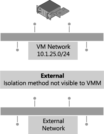
FIGURE 2-26 In externally defined networks, the isolation method is not visible to VMM.
Externally defined networks are included in this text only to note that VMM administrators need to work closely with their counterparts on the network team to make sure that a consistent model and design structure is being followed. Ideally, network administrators should plan the network configuration in partnership with VMM administrators to ensure that both parties agree on naming conventions and standards for how to define the fabric.
MORE INFO You can find more information on virtual switch extension managers in VMM and how to make use of them at http://technet.microsoft.com/enus/library/jj614619.aspx.
Key points
Considering the logical networks created for Contoso, there appears to be little or no requirement to isolate any of the logical networks defined on top of the Datacenter or Storage physical networks. That being said, you could easily justify using some form of isolation for front end web servers (assuming they were accessible from the public Internet) that were connected to the Datacenter network or for specialized servers and workloads that need to be isolated from others. You need to assess each logical network and determine what, if any, isolation methodologies you should apply in your environment.
The case for isolation for logical networks on the Provider network in the Contoso example is very clear, however, because there are multiple customers running workloads on the same physical infrastructure. Where a given physical network or VLANs have been dedicated to a particular customer, clearly no isolation will be required on the logical network since only that tenant’s traffic will exist on the network. However, in the case of shared networks, you must consider which isolation method is best suited to the customers’ requirements and is supported by the physical network. Network Virtualization clearly offers the most comprehensive and scalable solution but requires NVGRE gateway devices to allow virtual machines to communicate with networks in the same datacenter or VPN gateway devices to facilitate communication with a defined external network. VLAN/PVLAN isolation can be readily used, is well understood, and is supported by most existing network hardware, but has management issues at scale. The decision, ultimately, will be based on your business strategy, current and forecast growth patterns, and how quickly and easily you can acquire and deploy network gateways that support NVGRE and software-defined networking.
Step 4: Define network sites
At this point in the process, you can start to consider implementation details, reviewing each of the logical networks that you identified during the earlier parts of the process to decide where (i.e., in which physical location) they need to be deployed and to determine the set of network sites, IP pools, and MAC address pools needed to make the networks available and used in those locations.
Physical locations and host servers
It makes sense to make some logical networks available in all physical locations. Many of the cloud infrastructure networks, such as management, storage, and live migration, clearly are relevant to and should be made available everywhere while the availability of others should be restricted to specified locations. If your organization’s development team is located in a single location, it might be reasonable to ensure that the logical network you create for development workloads would be available only on servers in that location.
Having identified the physical locations on which a given logical network will be available, the next decision point is which of the Hyper-V hosts in that location should be configured to support it. Again, it makes sense that some of the logical networks should be made available on all of the host computers in that location, the logical networks you define for cloud infrastructure such as Management and Storage clearly being the most obvious candidates, though there may well be exceptions to this general rule. For example, not all servers will have access to network attached storage.
Servers may have been set aside for specific workloads or projects or allocated (dedicated) to specific tenants, and in these cases, you should ensure that the logical network that will carry those workloads is available only on those computers. To achieve this, you first need to define host groups. The recommend approach is to create a parent host group (for example Production as shown in Figure 2-27) that clearly identifies the group of dedicated servers and child host groups for each physical site where those servers will be located; Reading and Seattle in Figure 2-27, for example.

FIGURE 2-27 Creating host groups for dedicated servers.
Network adapters in Windows Server 2012 Hyper-V servers can be associated with multiple logical networks. However, there is no internal routing between them. If you want to allow virtual machines and host services configured on one logical network to communicate with those on another, you will need to deploy a router or gateway device.
Network sites (logical network definitions)
Network sites, otherwise known as logical network definitions, are used to define the VLANs and IP subnets that are to be associated with the logical network in each physical location. However, it is unnecessary to define network sites for all of your logical networks. The following key points replicated from the Configuring Logical Networking in VMM Overview section of the VMM documentation (available at http://technet.microsoft.com/enus/library/jj721568.aspx) set out the guidelines that will help you determine whether you need to define a network site for the logical network in a given physical location:
▪ If you want to use DHCP that is already available on the network, and you are not using VLANs, you do not have to create any network sites but as a recommended best practice, you should always aim to do so.
▪ If using VM networks that use Network Virtualization, you must create at least one network site and associate at least one IP subnet with the site as mentioned earlier. You can also assign a VLAN to the network site, as appropriate. Creating a network site with an IP subnet makes it possible to create an IP address pool for the logical network, which is necessary for Network Virtualization.
If the VM networks you create will not use Network Virtualization as an isolation mechanism, the following guidance applies:
▪ If you plan to use a load balancer that is managed by VMM to load-balance a service tier, create at least one network site and associate at least one IP subnet with the network site.
▪ If you want to create static IP address pools that VMM manages, create at least one network site and associate at least one IP subnet with the network site.
▪ If you want to use Dynamic Host Configuration Protocol (DHCP) that is already available on the network to assign IP addresses to virtual devices in a specified VLAN, create network sites with only VLANs assigned to them. With that said, it is strongly recommended that you fill in all the network properties in VMM, even if you’re not going to use VMM for IP address assignment and management.
IP address pools
If you associate one or more IP subnets with a network site, you can also create static IP address pools for those subnets. Static IP address pools make it possible for VMM to automatically allocate static IP addresses to Windows-based VMs that are running on any managed Hyper-V, VMware ESX, or Citrix XenServer host. VMM can automatically assign static IP addresses from the pool to stand-alone virtual machines, to virtual machines that are deployed as part of a service, and to physical computers when you use VMM to deploy them as Hyper-V hosts. Additionally, when you create a static IP address pool, you can define a reserved range of IP addresses that can be assigned to load balancers as virtual IP addresses. VMM automatically assigns a virtual IP address to a load balancer during the deployment of a load-balanced service tier.
As with network sites, it is unnecessary to define IP address pools for all of your network sites. The following key points replicated from the VMM documentation at http://technet.microsoft.com/en-us/library/jj721568.aspx set out the guidelines that will help you determine whether you need to do so:
▪ If your network configuration includes VM networks that use Network Virtualization, you must create IP address pools on both the logical network that provides the foundation for those VM networks, and on the VM networks themselves. If the virtual machines on the VM networks are configured to use DHCP, VMM will respond to the DHCP request with an address from an IP address pool.
▪ VLAN-based configuration: If you are using a VLAN-based network configuration, you can use either DHCP, if it is available, and/or IP address pools. To use IP address pools, create them on the logical network. They will automatically become available on the VM network.
▪ VM network that gives direct access to the logical network (“no isolation”): If you have a VM network that gives direct access to the underlying logical network, you can use either DHCP, if it is available, and/or IP address pools for that network. To use IP address pools, create them on the logical network. They will automatically become available on the VM network.
▪ If you are using external networks that are implemented through a vendor network-management console (in other words, if you will use a virtual switch extension manager), your IP address pools will be imported from the vendor network-management database. Therefore, do not create IP address pools in VMM.
MAC address pools
If a VM connected to the logical network will obtain IP addresses from a static IP address pool, you must also configure the VM to use a static MAC address. You can either specify the MAC address manually or have VMM automatically assign a MAC address from either a central MAC address pool or one that you have created for a specific network site.
Step 5: Deployment
Having defined the logical network, the host groups, network sites, IP address pools, and optionally, MAC addresses pools, the next step is to associate the network with the Hyper-V host computers. Although you can associate logical networks with each Hyper-V host manually or by using Windows PowerShell, to ensure consistency and simplify management across multiple hosts, it is far more efficient to define the required properties and capabilities within port profiles and logical switches. You’ll find the details for this process in Chapter 5, “Deployment.”
Naming conventions
As with everything else, defining and adhering to a naming convention for all the components of your virtualized networking solution is important. Logical network names should, as much as possible, help administrators clearly identify the main purpose and function and use a structure similar to the following:
[Environment] – [Optional Purpose]
Typical examples of this structure would be Production – Corporate, Production – Tenant, Development – Test, and so on. It is also strongly recommended that you add a high-level description to aid understanding.
Although network sites (logical network definitions) are created in the context of a logical network, naming conventions for these objects become particularly important when you start to use uplink port profiles and logical switches. Recall that when you create an uplink port profile, you select the network sites that represent connection to the required logical network. For example, if you have multiple sites called Reading, which one is linked to the logical network used for your corporate servers, which one is used by tenants, and which represents a connection to your development environment? Although the UI displays logical network names when you configure an uplink port profile, you need to pay close attention to make sure you choose the correct one, and hence a poor naming convention can lead to potential misconfiguration. As a result, it is recommended that you use convention for network sites similar to the following:
[Location] - [Logical Network Name]
Similarly, consider and arrive at an appropriate naming convention for the IP address and MAC address pools that are directly linked to the network site to help provide clarity around what a given address pool is used for. The following is a good starting point:
[Location] – [Logical Network Name] - [Purpose]
These are the recommended naming conventions for the logical network and the various components that depend on it, but this approach may not be appropriate for your specific environment. The point is, you need to arrive at a convention that clearly identifies the key components of the solution in your environment and what they are used for.