CHAPTER 5
Deployment
This chapter explains not only how logical switches can be deployed to a new Hyper-V host, but also how an existing standard switch can be migrated to use the new converged approach. The chapter will explain the different methods for applying a logical switch to a Hyper-V host and how existing Hyper-V hosts with standard switches can be migrated. It also covers best practices from the real world and early adopter customers. In addition, the text will address the common deployment scenarios and highlight known issues and workarounds regarding logical switches in VMM.
This chapter will:
▪ Review the requirements for logical switches
▪ Discuss the different options to deploy a logical switch to a Hyper-V host
▪ Explain how to migrate a standard switch to a logical switch
▪ List some known issues when deploying logical switches
Preparing for deployment
With VMM it is now possible to consistently configure identical capabilities for network adapters across multiple Hyper-V hosts by using logical switches, which consist of port profiles, uplink profiles, and classifications. Logical switches basically act as containers for the properties or capabilities that you want to deploy and configure for your network adapters.
To be able to deploy a logical switch, you need to prepare the following settings in VMM:
▪ Logical networks represented in VMM (see Chapter 2, “Logical networks”) such as the following:
• Management (used by Hyper-V hosts)
• Back End (used by Failover Cluster for Cluster Shared Volumes (CSV) and Live Migration)
• Storage (used by iSCSI or SMB 3.0 if available)
• Front End (used by virtual machines (VMs) and tenants)
▪ Appropriate VM networks since they will be used not only by the VMs but also by the uplink profiles (see Chapter 2)
▪ At least one uplink profile that contains that defines how the NIC team should be configured (see Chapter 3, “Port profiles”)
▪ A logical switch that contains all objects and specifies the network configuration that will be used on all Hyper-V hosts (see Chapter 4, “Logical switches”)
▪ Hyper-V hosts managed by VMM
Regardless of any port profiles and logical switches you plan to use in the configuration, each network adapter in a host can be allocated for use by VMs, for host management, neither of these options, or both of them. It is also important to review the prerequisites if you want to configure single-root I/O virtualization (SR-IOV) for network adapters on the host.
If you will not be using the bare-metal deployment capabilities of VMM to deploy your Hyper-V hosts, you will have to manually add all your hosts to VMM. To perform this task you must either be a member of the Administrator user role or a Delegated Administrator. The steps for doing this are described on TechNet at http://technet.microsoft.com/enus/library/gg610605.aspx. You can also use the Add-SCVMHost PowerShell cmdlet:
$RunAsAccount = Get-SCRunAsAccount -Name My Administrator
Add-SCVMHost MyHyperVHost -RemoteConnectEnabled $True -RemoteConnectPort 5900
   -VMHostGroup MyHosts -Credential $RunAsAccount
TIP When you add a host to the VMM management server, by default VMM automatically creates logical networks for those host physical network adapters that do not have logical networks defined on them. You might therefore want to consider clearing this option as described in Chapter 2.
Deploying logical switches
As discussed in Chapter 2, when a logical switch is applied to a network adapter in a Hyper-V host, VMM uses the information contained in the logical switch and the (selected) uplink port profile to create a Hyper-V virtual switch on the host and associate the network adapter with the required logical networks, VLAN, and IP subnets.
To deploy a logical switch, you must be a member of the Administrator or Delegated Administrator user role in VMM. In addition, when configuring virtual switches, delegated administrators can select only uplink port profiles that contain network sites that are in the administrative scope of their delegated privileges.
IMPORTANT When VMM creates the virtual switch, the host may temporarily lose network connectivity. This may have an adverse effect on other network operations in progress. As a result, the warning shown in Figure 5-1 will appear and you must first acknowledge this warning before you can continue with the deployment process.

FIGURE 5-1 Dialog box warning that the host may temporarily lose network connectivity.
There are some additional considerations when you are deploying logical switches onto physical network adapters that will be used for host management, especially when management traffic should only be carried on a specific VLAN.
NOTE These network adapters require special attention as they are used by the host operating system (or parent partition) to access the network. The VMM Agent also uses these adapters to communicate with the VMM server, and to make this work, you need to define a logical network and a VM network for host management (as discussed in Chapter 2).
In a tagged deployment, every data packet related to host management that is sent from the network adapter must be tagged with a specific VLAN ID. As a result, a logical switch deployed on physical network adapter used for management needs to be configured to add the appropriate VLAN ID to every packet that is sent from and to the host management logical network.
If the network port on the physical network switch has been configured for native VLAN on the trunk port, all untagged traffic is treated as destined for the Host Management VLAN. As a result, all packets sent from and to the management logical network will be unchanged by the logical switch.
Untagged host management network adapter
In an untagged scenario, management traffic is not tagged with a VLAN ID as mentioned above. This means two things from the perspective of physical network configuration:
▪ Management traffic generated by the host management adapter should not be tagged with a VLAN ID.
▪ The management network VLAN is actually set to be the native VLAN on the trunk port of the connected physical network switch.
To support untagged management traffic in VMM, define a logical network and set the VLAN ID for Network Site(s) within that network to 0 (as shown in Figure 5-2). VMM interprets this setting as meaning “no VLAN” and as a result, the logical switch will be configured to leave outbound network traffic unchanged
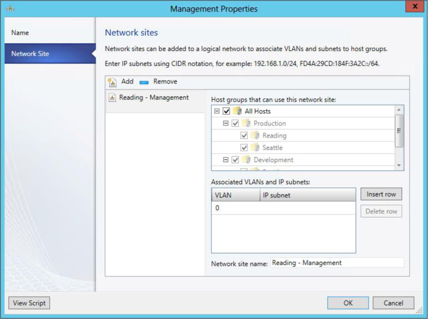
FIGURE 5-2 Example of an untagged host management logical network.
The workflow for deploying a logical switch in a tagged scenario is as follows:
1. Open the VMM admin console and switch to the Fabric workspace.
2. In the Fabric workspace, expand Servers, select All Hosts, and, if needed, the sub-host group where the host resides.
3. Select the target Hyper-V host and open the Properties dialog box.
4. In the Properties dialog box, select Virtual Switches.
5. Select New Virtual Switch and choose New Logical Switch.
6. Select the corresponding logical switch from the drop-down list.
7. Under Physical Adapters, add the two (or more) network adapters that should be used for this logical switch.
8. In the same view, next to the physical adapter, select the corresponding uplink port profile.
9. Select the logical switch and select New Virtual Network Adapter. This adds a virtual network adapter as part of the logical switch.
10. Select the newly added virtual network adapter and provide a meaningful name for the adapter.
11. For the management virtual network adapter, configure the following options as shown in Figure 5-3:
• If the IP address from the physical network adapter should be reused, select the option “This Virtual Network Adapter Inherits Settings From The Physical Management Adapter.” Note that this option is only available for the first vNIC connected to the switch; this would typically be the Management vNIC but this is not always the case.
• Under Connectivity, select the corresponding VM network, for example Management. There should be no option to select a VLAN.
• Under Port Profile, select the classification that matches the network, in this case Host Management.
• As the IP Address will be reused from the physical network adapter, no additional settings are required.
12. For additional virtual network adapters, such as the one used by Live Migration, configure the following options:
• After the name to be used for the virtual network adapter has been specified under Connectivity, select the corresponding VM network, for example Live Migration, and choose the appropriate VLAN if required.
• For the IP address configuration, choose whether DHCP or Static will be used to configure the Live Migration adapter. When choosing Static, select IP Pool and specify the IPv4 address. If you don’t specify an address, VMM will pick one automatically from the pool.
• Under Port Profile, select the classification that matches the network, in this case Live Migration.
13. Repeat the above step for all virtual network adapters required for this configuration.
14. After the configuration has been completed, click OK to close the Properties page. This will initiate the logical switch creation on the Hyper-V host.
15. This job might take a while to finish and if you're connected to the Hyper-V host using RDP you will most likely lose your connection.
16. When the job has finished, log on to the Hyper-V host and verify the configuration. If the IP address has been transferred from the physical to the virtual network adapter, make sure that the gateway and DNS Server settings were as well.

FIGURE 5-3 Logical switch deployment using untagged host management.
Once the logical switch has been created and the configuration has been verified on the Hyper-V host, the host is ready for providing networking to VM workloads.
Tagged host management network adapter
In a tagged scenario, the physical network switch port is configured in trunk mode, and host management traffic is on a particular VLAN. To support tagged management traffic in VMM, you should define a logical network for management and set the VLAN ID for Network Sites within that network to the appropriate value (110 in Figure 5-4).
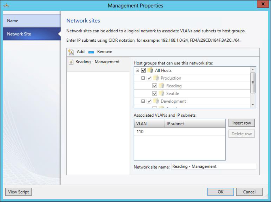
FIGURE 5-4 Tagged host management logical network.
It’s important to understand the subtle differences between the tagged VLAN scenario and the untagged scenario. In the tagged scenario, VMM has to tag the virtual network adapter used for host management with the particular VLAN ID specified in order for host management traffic to flow through the management virtual network adapter. As the VLAN configuration happens at the end of the virtual switch configuration, it is important that VMM has uninterrupted access to the Hyper-V host. This means that VMM requires connectivity through another management interface until it can complete the VLAN configuration of the new management virtual network adapter.
The workflow for deploying a logical switch in a tagged scenario will look like the following:
1. Deploy a logical switch with one physical network adapter as an uplink to keep the other physical network adapter for management connectivity.
2. When the logical switch creation succeeds, add the other physical network adapter to the logical switch.
Before proceeding, therefore, you must make sure that there are at least two physical network adapters that are marked as Used By Management:
1. In the VMM admin console, switch to the Fabric workspace.
2. In the Fabric workspace, expand Servers, select All Hosts, and, if needed, the sub-host group where the host resides.
3. Select the Hyper-V host that should be configured and open its Properties dialog box.
4. In the Properties dialog box, select Hardware.
5. Navigate to Network Adapters and select the physical network adapter that will be used for host management. Ensure the option Used By Management is selected.
6. Repeat these steps for any other physical network adapters required for this configuration.
Next, proceed with the deployment of the logical switch to the Hyper-V host of choice. Follow these steps to deploy the first virtual switch using the logical switch:
1. In VMM, change to the Fabric workspace.
2. In the Fabric workspace, expand Servers, select All Hosts, and, if needed, the sub-host group where the host resides.
3. Select the target Hyper-V host and open its Properties dialog box.
4. In the Properties dialog box and select Virtual Switches.
5. Select New Virtual Switch and choose New Logical Switch.
6. Select the appropriate logical switch from the drop-down list.
7. Under Physical Adapters, add the first, and only the first, network adapter that should be used for this logical switch.
8. In the same view, next to the physical adapter, select the corresponding uplink port profile.
9. Select the logical switch and select New Virtual Network Adapter. This adds a virtual network adapter as part of the logical switch.
10. Select the newly added virtual network adapter and provide a meaningful name to be used for the adapter.
11. For the management virtual network adapter, configure the following options as shown in Figure 5-5:
• If possible and if not affecting the other connectivity, select the This Virtual Network Adapter Inherits Settings From The Physical Management Adapter option.
• Under Connectivity, select the corresponding VM network, for example Management. There should be the option to select the required VLAN.
• Under Port Profile, select the classification that matches the network, in this case Host Management.
• As the IP address will be reused from the physical network adapter, no additional settings are required.
12. For the additional virtual network adapters, such as the one used for Live Migration, configure the following options:
• After the name to be used for the virtual network adapter has been specified, select the corresponding VM network, for example Live Migration, and choose the appropriate VLAN if required.
• For the IP address configuration, choose DHCP or Static to configure the Live Migration adapter. When choosing Static, select IP Pool and specify the IPv4 address. If you don’t specify an address, VMM will pick one automatically from the pool.
• Under Port Profile, select the classification that matches the network, in this case Live Migration.
13. Repeat these steps for all virtual network adapters required for this configuration.
14. After the configuration has been completed, click OK to close the Properties page. This will initiate the logical switch creation on the Hyper-V host.
15. This job might take a while to complete, and if you’re connected to the Hyper-V host using RDP you will most likely lose the connection.
16. When the job has finished, log on to the Hyper-V host and verify the configuration. If the IP address has been transferred from the physical to the virtual network adapter, make sure the gateway and DNS Server were as well.
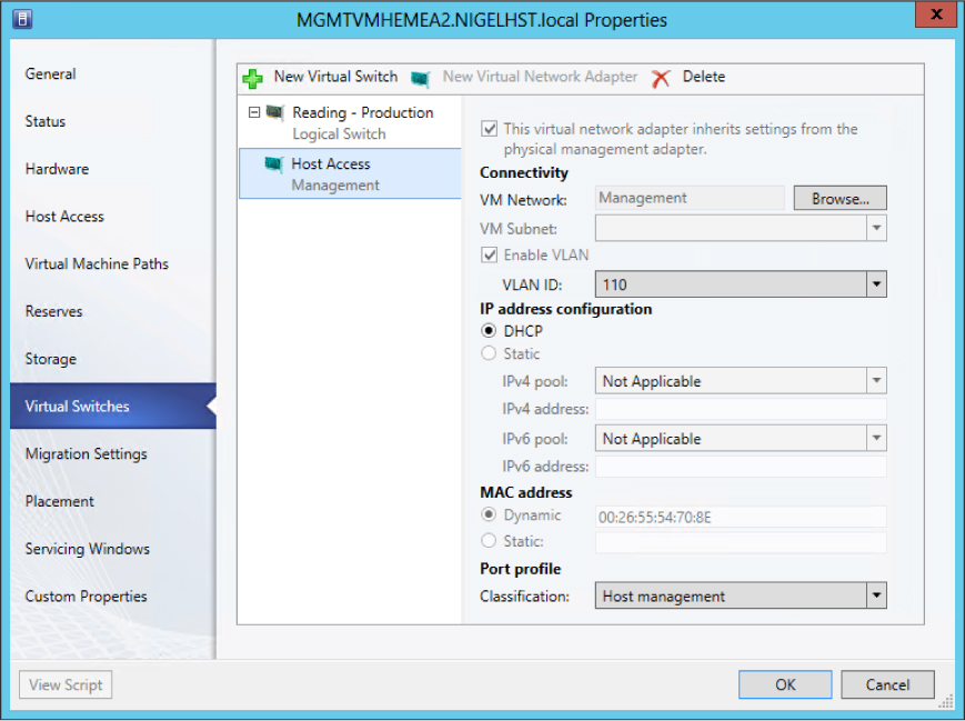
FIGURE 5-5 Logical switch deployment using tagged host management
When the logical switch has been created and the configuration has been verified on the Hyper-V host, the host is ready for providing networking to VM workloads.
For automation and standardization, you might want to copy and customize the Windows PowerShell script that VMM can display at the end of the wizard before you click OK. An example of a simple script to deploy without virtual network adapters might look like the following:
$VMMServerName = MyVMMServer.fqdn
$HyperVName = MyHyperVHost.fqdn
$adapterName = MyEthernetAdapterName
$NativeUplinkPortProfileSetName = MyUplinkAdapterName
$LogicalSwitchName = MyLogicalSwitchName

$VMM = Cet-SCVMMServer -ComputerName SVMMServerName
$vmHost = Cet-SCVMHost -ComputerName SHyperVName -VMMServer $VMM
$networkAdapter = Get-SCVMHostNetworkAdapter -VMHost SvmHost | Where-Object
   -FilterScript { $PSItem.Connect!onName -eq $adapterName }
$uplinkPortProfileSet = Get-SCUplinkPortProfileSet -Name $NativeUplinkPortProfileSetName
   -VMMServer SVMM
$logical Switch = Get-SCLogical Switch -Name $LogicalSwitchName -VMMServer $VMM

Set-SCVMHostNetworkAdapter -VMHostNetworkAdapter SnetworkAdapter
   -Upli nkPortProfileSet $upli nkPortProfileSet
New-SCVirtualNetwork -VMHost $vmHost -VMHostNetworkAdapters $networkAdapter
   -Logi calSwitch $Iogical Switch
Bare-metal deployment
Another way to deploy logical switches is by making use of the bare-metal deployment capabilities of VMM. VMM provides the capability to discover physical computers on the network and then automatically install the Windows Server operating system on those computers and convert them into managed Hyper-V hosts. This means the targeted physical computer can be a computer that does not have an operating system installed, often referred to as a bare-metal computer, or it can be a computer on which you want to overwrite an existing operating system. This chapter doesn’t go into details about how to perform bare-metal deployment, but instead will highlight how to configure logical switches as part of bare-metal deployment.
The configuration required for bare-metal deployment is done in the host profile located in the VMM Library. In VMM 2012 SP1 this profile contains not only the Hyper-V configuration but also the entire physical and virtual network adapter configuration (see Figure 5-6).
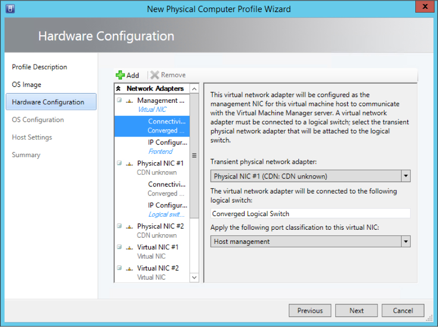
FIGURE 5-6 Hyper-V host profile using logical switch.
If a virtual network adapter is used for management, the setting Create A Virtual Network Adapter As The Management NIC has to be selected. Also, the IP Configuration must specify whether DHCP or fixed IP addresses will be used.
When initiating a bare-metal deployment, the targeted Hyper-V host is restarted. This is initiated by an out-of-band management action. After the restart, the host boots into WinPE mode where a discovery of the host hardware is performed. This discovery is key to getting insights into how to apply the profile to the physical network adapters (see Figure 5-7). It’s always good to have the MAC addresses available to easily identify the primary adapters.
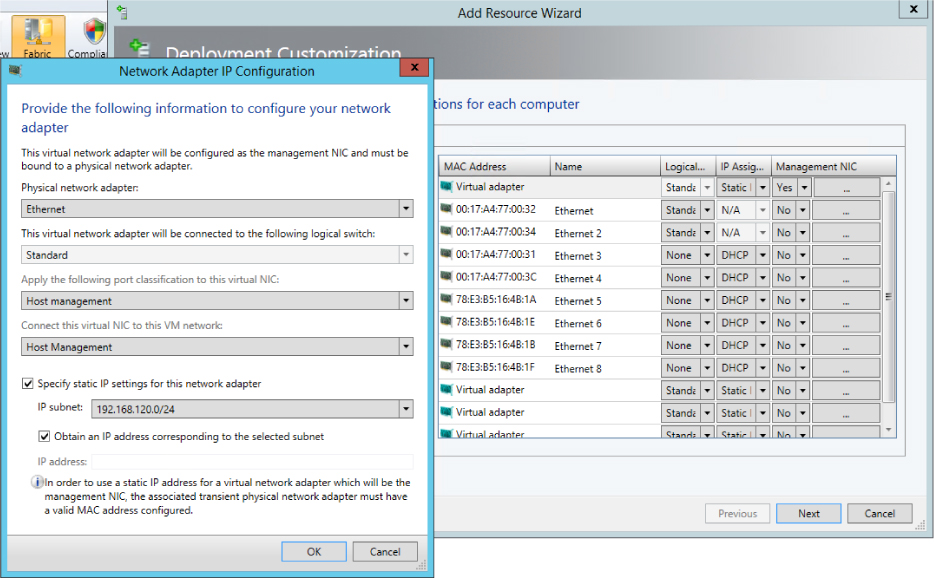
FIGURE 5-7 Bare-metal deployment network configuration.
In summary, bare-metal deployment dramatically reduces the time required to install a Hyper-V host and simplifies the deployment of logical switches since this is already part of the installation and configuration process.
Migrating from a standard switch to a logical switch
Of course not every environment is a “greenfield” in which you can build and deploy logical switches on brand new Hyper-V hosts. In established environments, you may find that standard Hyper-V switches have been deployed onto network adapters in a number of Hyper-V hosts. Although VMM will recognize and detect the presence of a standard switch (as you can see in Figure 5-8), it provides the administrator with limited management capability. Unfortunately, once the physical network adapter has been associated with a standard switch you cannot subsequently upgrade it to a logical switch. You must first disconnect and remove the standard switch and any associated virtual network interface cards (vNIC) from the network adapter before you begin to deploy the logical switch.
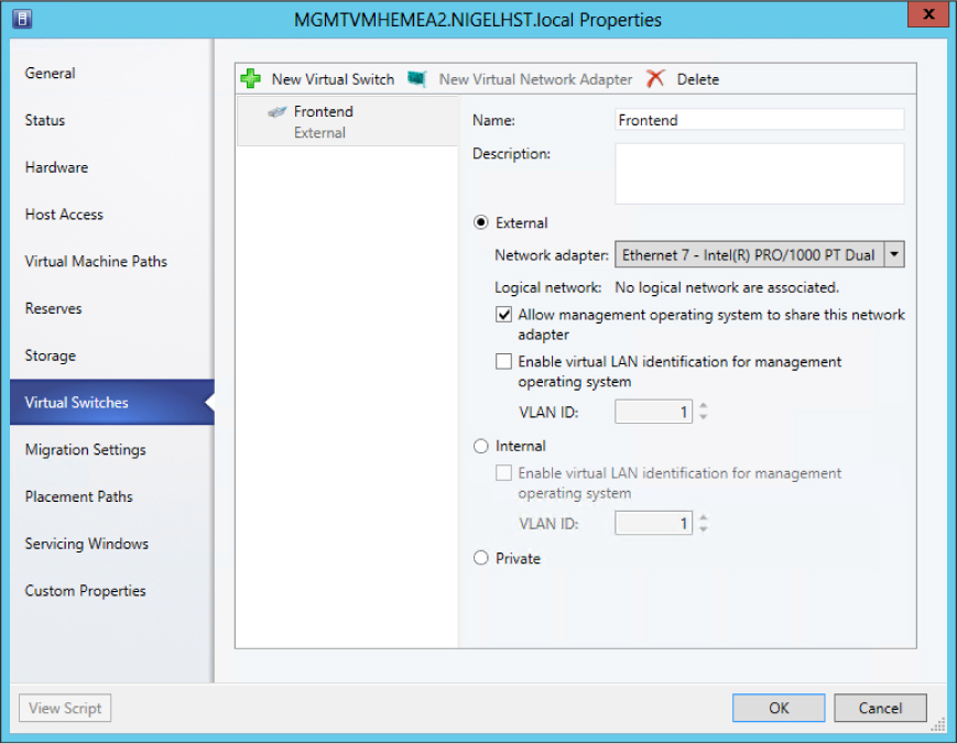
FIGURE 5-8 How a Standard Hyper-V switch is represented in VMM.
Preparation
You must first perform a few tasks before proceeding with the virtual switch migration. First, you must put the Hyper-V host into maintenance mode. To do so, in VMM, right-click the Hyper-V host and select Start Maintenance Mode as shown in Figure 5-9 or selecting the option from the ribbon.
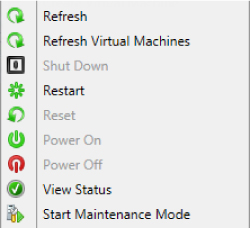
FIGURE 5-9 Enabling maintenance mode on a Hyper-V host in VMM.
This evacuation process can be used to move all VMs from one host in a cluster to another host in the cluster by using Live Migration. If the host is not part of a cluster, or if no compatible Hyper-V host is available, the VMs will be put into saved state, which causes users to lose service. This method can also be used for non-highly available VMs running on a clustered Hyper-V host.
Even if the Hyper-V host is ready in theory for maintenance actions, be sure to check first that no VMs remain on this host. You can do this using Windows PowerShell by running the following command:
Disable-SCVMHost -VMHost MyHyperVHost -MoveWithinCluster
IMPORTANT Don't confuse this command with Stop-SCVMHost, which would send a stop command to the baseboard management controller.
In addition, whenever you perform intensive network changes, it is recommended that you connect to the console using an out-of-band interface rather than an RDP connection to the management network adapter.
NOTE If VMM has been integrated with Microsoft System Center 2012 Operations Manager, the maintenance mode information will be passed to the monitoring system. This can help ensure that there are no unnecessary alerts when changing network connectivity or rebooting the system.
Transitioning
Because there isn’t an actual migration action to change from a standard switch to a logical switch, you actually first need to break the current configuration. To do this, delete the existing virtual switch using the Hyper-V Management Console or by using the Remove-VMSwitch cmdlet like this:
Remove-VMSwitch -Name MyVirtualSwitchName
This operation will also remove all virtual network adapters and their configuration. As mentioned in the previous section, be sure to use an out-of-band interface when applying this configuration change.
After the virtual switch has been successfully deleted, you can then remove the network team. This can be done in Server Manager or by using the Remove-NetLbfoTeam cmdlet like this:
Remove-NetLbfoTeam -Name MyNetworkTeamName
Make sure that the first network adapter now has the management IP address configured. If this part of the configuration is lost, you will need to configure it manually, including the DNS servers and gateway.
The host should now be back online, but make sure network connectivity and especially the connection to the VMM management server is working as expected.
To reflect these changes in VMM, the Hyper-V host configuration has to be updated before deploying the logical switch. By default, the Host Refresh job (HostUpdateInterval) runs every 30 minutes, but to make sure the hardware changes are immediately represented in VMM, you can start a manual refresh job as shown in Figure 5-10. When this is finished after a few seconds, be sure to verify the information in the Hyper-V host properties by checking the Virtual Switches tab. This should now be empty and should no longer display a standard switch.
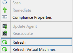
FIGURE 5-10 Refreshing a Hyper-V host in VMM.
Once the host configuration has been cleaned, the logical switch can be deployed from the VMM console. The detailed steps for how to configure a logical switch with an untagged or tagged VLAN environment has already been described earlier in this chapter. You should disable maintenance mode once the logical switch has been deployed successfully to allow the virtual machines to be migrated back to the host.
Known deployment issues
The following sections describe some known issues concerning the deployment of logical switches using VMM.
Limitations for an existing NIC team
It’s very important to know that VMM does not support the deployment of logical switches to Windows Server 2012 Hyper-V hosts that have already have been configured with a NIC team. This means before you can proceed with deployment, the existing NIC team must be removed. You can either remove one adapter from the NIC team, which can then be used for the logical switch, and do the clean-up later; or you can remove the complete NIC team and add both network adapters to the new logical switch.
Before proceeding with logical switch deployment however, always first make sure that your Hyper-V hosts are configured with the correct IP address, subnet mask, gateway, and DNS servers. Also perform a host refresh in VMM to make sure the new configuration is reflected correctly. This can also be performed by using Windows PowerShell as follows:
Read-SCVM Host -VMHost MyHyperVHost
An alternative and much more straightforward option is to leverage bare-metal deployment for Hyper-V host installation as described earlier in this chapter. In this scenario, logical switches can be provisioned right away as an integral step of the deployment workflow. This eliminates the need for swapping physical NICs one by one between teams.
To conclude, the only way to provision a logical switch to a Hyper-V host is to take over raw physical NICs that are not currently assigned to NIC teams or virtual switches.
Deployment fails if host is out-of-scope
When using host groups in VMM to organize your Hyper-V hosts, the deployment of a logical switch on a Hyper-V host can fail with error 26874:
Error (26874)
This operation is not permitted since uplink port profile set <adapterGUIDstring> in physical adapter <nameGUIDstring> on host <hostNameFQDN> would go out of scope for host
Recommended Action:
Delete the logical switch instance on the affected host(s) and retry the operation.
This can happen if the host on which you are attempting to deploy the logical switch is not a member of the host groups that are defined in every one of the network sites included within the selected uplink port profile. To resolve this issue, you simply need to add the host computer to the appropriate host groups.
Deployment fails when using different network adapter types
When deploying a logical switch on a Hyper-V host that has different types of network adapters, the deployment might fail with the following error message:
Warning (25259)
Error while applying physical adapter network settings to teamed adapter. Error code details 2147942484
Recommended Action
Update the network settings on the host if the virtual network adapter is connected to the host.
When deploying a logical switch to a host with two or more network adapters from different brands (Broadcom and Intel, for example), the job fails with the error 2912. Since VMM uses the first physical network adapter in the list and creates the NIC team with this network adapter, the switch inherits the capabilities of this network adapter, such as VMQ, SRIOV, Task Offload, MTU size, and so on. If you add additional network adapters that do not support these capabilities to the NIC team, the job will fail.
To work around this problem, the existing network team must be destroyed, which means that all existing network connections, and if configured, virtual network adapters, will fail (lose connectivity). To avoid this situation, always make sure to start with the physical network adapter that has the least possible capabilities followed by other physical network adapters that have the same or better capabilities. This will ensure the team works with different brands or adapter types.
Just for the record, the same thing happens in the default NIC Teaming configuration wizard when you try to add a less capable physical network adapter to an existing network team.