As you learned in Chapter 7, TCP/IP is built on a set of dynamic specifications that are constantly modified and updated through a process known as Request for Comments (RFCs). There is an RFC for every component of the TCP/IP protocol suite, so you can imagine how many are associated with routing. As a precursor to working with routers, you will explore the organizations that deal with the TCP/IP protocol suite, including RFCs.
Taking communications off the LAN and moving them out to other networks and ultimately the Internet requires a re-examination of a number of concepts, components, and software you have already worked with. For example, you’ve configured client computers to communicate with other computers on the local network as well as computers on remote networks using the default gateway. Now you need to look at routing from the perspective of the router itself to learn how to configure the routers to make those connections beyond the local network possible.
In addition, you will work with some important components that really enhance IP routing, in particular Network Address Translation (NAT) and dynamic routing. These two technologies are critical for communication over the Internet and the protection of any private network you want to connect to the Internet. In this chapter, you’ll explore some additional organizations and then you’ll install and configure routers, NAT, and dynamic routing protocols to see how they work in the real world.
![]() 20 MINUTES
20 MINUTES
Lab Exercise 8.01: Governing Bodies, Part 2
The TCP/IP suite is so important to modern networking that both the textbook and Lab Manual devote multiple chapters to the various components of TCP/IP. These chapters cover in detail IPv4 and IPv6 addressing, IP routing, DNS and DHCP, VPNs, and VLANs. In almost every chapter, you will work with various TCP/IP utilities.
Just as there are organizations that handle the specifications and management of Ethernet and cabling, so too are there organizations that handle the specifications and management of the TCP/IP protocol suite. Before starting your journey through the wonderful world of routing, it is a good time to introduce you to some of these organizations.
Learning Objectives
In this lab, you’ll explore various organizations that are responsible for the development and management of standards for TCP/IP, the Internet, and the World Wide Web. By the end of this lab, you will be able to
![]() Describe the purpose and detail some of the features of the organizations responsible for the TCP/IP standards, Internet addressing, and domain naming
Describe the purpose and detail some of the features of the organizations responsible for the TCP/IP standards, Internet addressing, and domain naming
![]() Research and report on some of the paramount RFCs
Research and report on some of the paramount RFCs
Lab Materials and Setup
The materials you need for this lab are
![]() Internet access
Internet access
![]() Pencil and paper
Pencil and paper
Getting Down to Business
Imagine for a moment you are working for a large company that wants to have their own pool of public IP addresses. Or you have decided to launch your own Web site discussing, trading, and selling vintage guitars, and you want a great domain name like www.vintageguitars.com, also known as a Uniform Resource Locator (URL). Who knows, you might decide to write the next all-encompassing dynamic routing protocol. All of these situations are administered by official organizations that help to manage the TCP/IP protocol suite. In the next few steps you will explore these organizations and document some of the information you uncover.
Step 1 Similar to the International Organization for Standardization (ISO), the Internet Corporation for Assigned Names and Numbers (ICANN) owns and operates some of the other key organizations responsible for TCP/IP and the Internet. Open your Web browser and enter this URL: www.icann.org/en/about. Record who ICANN is, how long they have been around, and their mission statement.
![]()
![]()
Step 2 Navigate to this Web site, www.iana.org/about/. This is the Internet Assigned Numbers Authority (IANA). Write a short summary of who they are, when they were founded, and what their main responsibilities are.
![]()
![]()
Step 3 IANA works closely with the Internet Society (ISOC). Record some of the facts you learn about ISOC at www.internetsociety.org/who-we-are.
![]()
![]()
Step 4 There are numerous organizations responsible for steering the Internet. Yet another of these organizations is the Internet Engineering Task Force (IETF). What are some of the characteristics of the IETF? Check them out at www.ietf.org/about.
![]()
![]()
Step 5 One of the most important contributions of the IETF is the stewardship of the RFC database. The RFCs are the open source recommendations and standards for the Internet (more specifically, TCP/IP is defined by RFCs). The main repository for the RFCs is the RFC Editor at www.rfc-editor.org. Once there, click Search for an RFC and its metadata, and then search for the following RFCs and document some of the information pertaining to the standard.

As you progress through the rest of the lab exercises in this Lab Manual, you may find it interesting and beneficial to consult the RFCs as you learn about the application of the protocols of the TCP/IP protocol suite. For example, in the next chapter you will be working with the Simple Mail Transfer Protocol (SMTP), Post Office Protocol, version 3 (POP3), and Internet Message Access Protocol version 4 (IMAP4). Can you find the RFCs that define these protocols?
![]()
![]()
![]() 45 MINUTES
45 MINUTES
Lab Exercise 8.02: Installing and Configuring Routers
In the previous chapter, you learned that in order to move TCP/IP packets from a machine on the local network (LAN) to a machine on a remote network, like the Internet (WAN), you needed to use a router. Until now, you have only been responsible for configuring a PC to use the default gateway to send packets destined for remote networks to the near port of the router. The router then handles the delivery of these packets from the local network to the remote network.
Now it is time to explore the fine details of installing and configuring routers. You will begin with this lab exercise, where you will install and configure one router, creating two networks. In Lab Exercise 8.03, you will add additional routers (creating additional networks) emulating the router configuration and management that an enterprise network technician would be responsible for.
![]() Tech Tip
Tech Tip
The following routing labs were designed to utilize the excellent capabilities of inexpensive wireless routers made by companies like Linksys, Belkin (who owns Linksys, but also maintains their own brand), and NETGEAR. For the lab exercises in this chapter, an inexpensive router will route packets between two networks, enable the configuration of NAT and port forwarding, and create dynamic routing tables via Routing Information Protocol (RIP).
If you have access to Cisco or Juniper routers such as the Cisco 2600 series routers or the Juniper J-series routers, they will obviously meet the requirements of the following labs. The full configuration of these routers is beyond the scope of these lab exercises (as well as the objectives for the CompTIA Network+ exam).
Learning Objectives
When you have completed this lab exercise, you will be able to
![]() Design and implement a routed, two-network infrastructure
Design and implement a routed, two-network infrastructure
![]() Physically install router hardware
Physically install router hardware
![]() Configure multiple interfaces on Ethernet routers
Configure multiple interfaces on Ethernet routers
![]() Implement static routes in routers
Implement static routes in routers
Lab Materials and Setup
Preferably, you will have access to the small “network lab” you assembled in the previous chapter’s exercises. The materials you’ll need for this lab are
![]() Pencil and paper
Pencil and paper
![]() Two or more PCs
Two or more PCs
![]() One router
One router
![]() Two eight-port Ethernet switches (Simple NETGEAR or Linksys Workgroup switches are acceptable)
Two eight-port Ethernet switches (Simple NETGEAR or Linksys Workgroup switches are acceptable)
![]() Appropriate UTP cabling
Appropriate UTP cabling
Getting Down to Business
Maggie stops by the Network Lab to see how you are progressing. She finds that you not only have the small network up and running, but have configured both static and dynamic IP addressing. You demonstrate the communication between the two networks over the router using the ping utility. Packets are successfully sent to one of the machines on the remote network, which successfully replies to one of the machines on the local network.
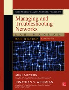
She is duly impressed and asks if you are up for experimenting with the configuration of the router. You respond with “You bet!” and begin to disassemble the Network Lab. Maggie stops you and says you won’t need to disassemble the physical setup, but she is going to give you new network IDs that you’ll need to configure.
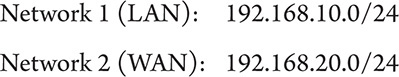
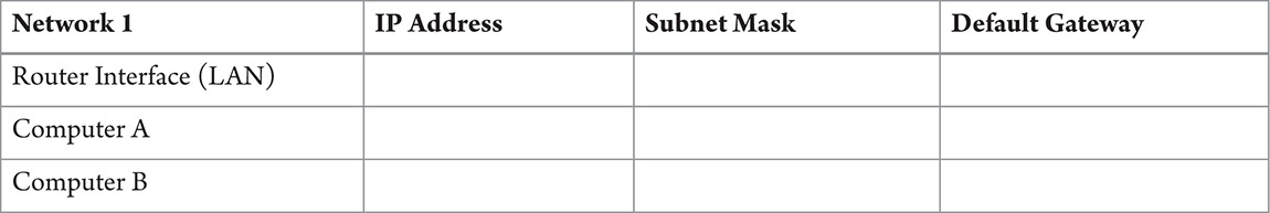
Step 1 Based on these network IDs for the two networks, complete the following table, filling in the appropriate IP addresses for each router interface and each computer. Remember, as you learned in Chapter 7, to plan out your network addressing scheme. Typically, a range of addresses will be set aside for network routers, servers, and network printers.
Step 2 Verify the configuration of the physical setup as follows using Figure 8-1.

FIGURE 8-1 Physical layout of the network for Lab Exercise 8.01
Step 3 Armed with your addresses for the LAN and WAN interfaces, launch your browser and open the router configuration utility. Consult the user’s manual or the Internet to determine the correct information for the specific model you are using. The default address is commonly 192.168.1.1. It’s also common for the default username to be “admin” and the default password to be the never secure “password.” You should arrive at the main setup screen, similar to Figure 8-2.
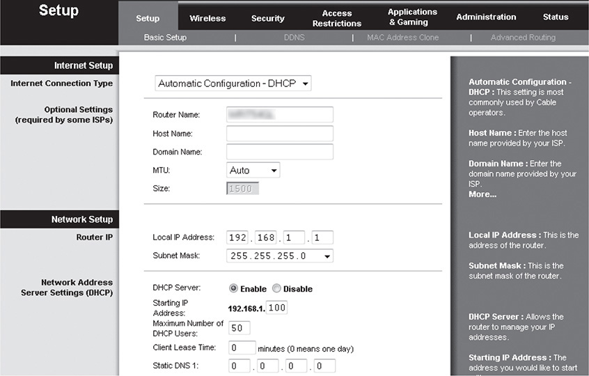
FIGURE 8-2 Title page of a sample configuration utility
Step 4 You will begin by configuring the IP addresses of the WAN interface and the LAN interface. Start by giving the WAN interface a static IP. Configure the IP address, subnet mask, and default gateway for the WAN interface. For the default gateway, enter an IP address for the second router interface on the same network (in our Network Lab, this is 192.168.20.2). Next, configure the LAN interface IP address and subnet mask. Disable DHCP. Save your changes.
![]() Hint
Hint
Since you have just changed the IP address of the router’s WAN and LAN interfaces, you have effectively changed the IP address for the Setup Web page. In order to re-enter the router setup utility, you will need to configure the computer from which you are accessing it to be on the correct network and use the new IP address for the router. If the IP addresses were improperly configured, you would have to reset the router. There is a small recessed button on the back of most routers. Pressing the reset button for 20 seconds or so will reset the router to default values. Use the default values to once again enter the Setup page and reconfigure the lab exercise settings.
Step 5 Next, find the advanced routing settings, and disable Network Address Translation (NAT). Usually, selecting “Router” instead of “Gateway” does the trick, and allows properly routed packets to travel freely between the two networks. Be sure to save your changes.
Then, display your routing table. This is a simple static routing table that is created when you configure the LAN and WAN interfaces. Note the destination network, subnet mask, gateway, hop count (metric), and interfaces for each entry. See Figure 8-3.
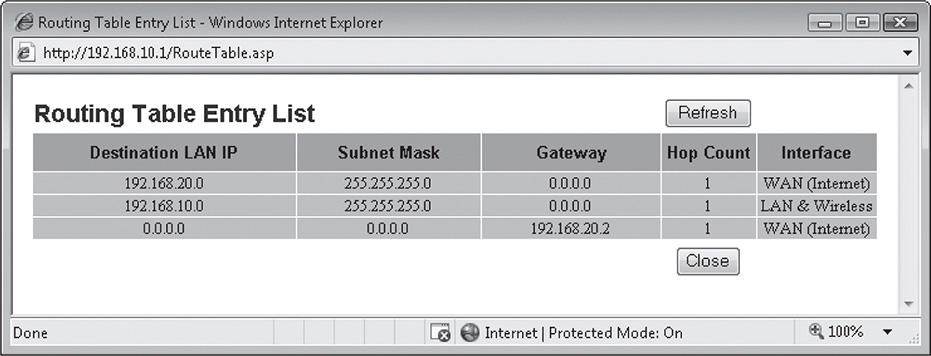
FIGURE 8-3 Routing table for the router in the Network Lab

![]() Cross-Reference
Cross-Reference
Review the “Routing Tables” section of Chapter 8 in the Mike Meyers’ CompTIA Network+ Guide to Managing and Troubleshooting Networks textbook. This will help you better understand the details of the specific entries in the preceding table.
Step 6 Find the security settings, and disable the firewall. You would probably not do this if you were using the router to access the Internet, but these two segments are private LANs and will be isolated from the Internet. Save your changes.
Step 7 Now configure each of the computers on both Network 1 and Network 2. Remember to use the router’s IP address for the network you are configuring as the default gateway for each of the systems on that network. You will also want to disable the Windows firewall on each machine.
Step 8 On one of the computers on Network 2 (WAN), open a command prompt, and using the ping utility, record the results of testing the communication with the following interfaces:
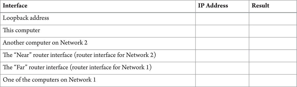
If any or all of the prior communication tests fail, try to isolate the problem (individual computer, router, or switch). Depending on your findings, check the cabling, review the configurations of the PCs, or review the configuration of the router. If everything checks out, congratulations! You have a routed internetwork.
Lab Exercise 8.03: Exploring NAT
Network Address Translation (NAT) is a powerful technology that enables many network clients on a TCP/IP network to share a single Internet connection. This provides an extremely important function: the conservation of the increasingly scarce, public IPv4 addresses distributed by IANA. Most popular Internet gateway routers and home network routers on the market have built-in NAT functionality.
Since, by design, NAT blocks access from computers on the public network to computers on the private network, nobody can connect to and use any services on your computer. Normally, this is a good thing; it is difficult for a malicious program to attack your computer based solely on IP address. But what if you want to host a game or a Web site? Nobody would be able to access your computer with NAT enabled. NAT uses logical ports to translate the packets from the private IP address to the public IP address and vice versa, so you can authorize packets to be forwarded through logical ports for specific applications to the specific computer hosting that application.
The competent network tech (you) should be well versed with the concepts of NAT. You should be able to identify the various versions of NAT and provide their functional definitions. You need to practice enabling NAT on both small office/home office (SOHO) routers and commercial routers until you have mastered it. Lastly, to ensure unhindered communication when necessary, you will configure port forwarding. When machines on the private network must be accessed from the outside world (such as Web servers, mail servers, terminal servers), port forwarding is the way to go!
In this lab, you will explore Network Address Translation.
Learning Objectives
In this lab, you will explain the function of NAT. When you have completed this lab, you will be able to
![]() Define the versions of NAT
Define the versions of NAT
![]() Implement NAT on a SOHO router
Implement NAT on a SOHO router
![]() Configure port forwarding to allow applications to pass through the router from the outside world
Configure port forwarding to allow applications to pass through the router from the outside world
Lab Materials and Setup
The materials you need for this lab are
![]() Pencil and paper
Pencil and paper
![]() The Mike Meyers’ CompTIA Network+ Guide to Managing and Troubleshooting Networks textbook
The Mike Meyers’ CompTIA Network+ Guide to Managing and Troubleshooting Networks textbook
![]() Internet access
Internet access
![]() The basic one-router, two-switch, four-computer lab network from the prior lab exercise
The basic one-router, two-switch, four-computer lab network from the prior lab exercise
Getting Down to Business
Network techs, administrators, and engineers often find themselves working beyond the traditional workday of 9:00 A.M. to 5:00 P.M. that other business professionals enjoy. Often they continue to work utilizing personal computers in the privacy of their own homes, only to find when they return to the office the following day that they could really use an item of information that they left on their home computer. There are many tools that allow you to connect to a remote computer to share files and folders or even run programs as if you were on the actual machine. Windows provides one such tool in the Remote Desktop utility.
Until now, you have been treating the routers you are working with as internal-only routers, so they are “wide open” to communication from both the local segment and the remote segment. Since it is not unusual for IT personnel at ITCF to access their home computers from the office using Remote Desktop, Maggie asks you to research how to configure the home systems to allow this communication. She reminds you that the SOHO routers will inevitably have NAT enabled to allow one external IP address to service multiple internal computers, as well as to protect those computers from unwanted access from the Internet.
You’ll need to explore the types of NAT, configure the computers on your lab network for Remote Desktop, and then enable routers to simulate the SOHO routers utilizing NAT. You’ll want to try Remote Desktop after NAT is enabled, and then configure port forwarding to allow Remote Desktop to access machines on the local segment from machines on the remote segment.
Step 1 Using the “Network Address Translation” section from Chapter 8 in the Mike Meyers’ CompTIA Network+ Guide to Managing and Troubleshooting Networks textbook, and resources from the Internet, complete the following table outlining the various flavors of NAT.

Step 2 Now using the network lab setup, log on to one of the machines on Network 2 (WAN) and use the Remote Desktop Connection to connect to one of the machines on Network 1 (LAN).
![]() Tech Tip
Tech Tip
A quick refresher on Remote Desktop:
1. First, make sure that both systems have been enabled to use the Remote Desktop Connection. In Windows 7/8/8.1, navigate to Control Panel | System and Security | System | Allow remote access. Under the Remote Desktop settings, enable Allow connections from computers running any version of Remote Desktop (less secure) as in Figure 8-4.

FIGURE 8-4 Windows 7 Professional System Properties Remote tab
2. Click Start | All Programs | Accessories | Remote Desktop Connection.
3. Enter the IP address of the remote machine.
4. You will then be prompted for a Username and Password.
5. If you entered the proper credentials, you should now have control of the remote computer.
You will explore the Remote Desktop utility in much greater detail in Chapter 14, “Remote Connectivity.”
What are the results?
![]()
![]()
Step 3 Now enter the router configuration utility (remember to use the new IP address since the router no longer has the default settings). Find the advanced routing settings, and enable Network Address Translation (NAT), hiding all of the addresses on Network 1 from systems on Network 2. Usually, selecting “Gateway” instead of “Router” will do the trick. Save your settings.
Step 4 Log on to one of the machines on Network 2 (WAN) and use the Remote Desktop Connection to connect to one of the machines on Network 1 (LAN). What are the results? Can you ping any of the computers on Network 1 from the computers on Network 2? How about the opposite direction, Network 2 from Network 1? Why can or can’t you communicate anymore?

Step 5 Once again, enter the router configuration utility and find the settings that deal with applications and games (Figure 8-5). You are going to configure the router to pass the Remote Desktop Protocol (RDP) by enabling the proper port that RDP uses, 3389, and link it with the specific IP address of the machine that you want to establish a Remote Desktop Connection with. This procedure enables port forwarding from systems on Network 2 that want to establish Remote Desktop connections with the specific machine on Network 1. Save your changes.

FIGURE 8-5 Configuring port range forwarding on a sample router
Although you have been working from the same initial network IDs that are shown in the figure, you may be using a different computer with a different IP address for the Remote Desktop connection. Make sure that you include your address when configuring and enabling port forwarding.
Step 6 Once again, log on to one of the machines on Network 2 (WAN) and launch the Remote Desktop Connection applet. To connect to the computer on Network 1 (LAN), you will have to use the IP address of the router. Your request will then be forwarded to the computer matching the IP address you configured to receive packets through the port number for the RDP. What are the results? Can you ping any of the computers on Network 1 from the computers on Network 2? How about the opposite direction, Network 2 from Network 1? Why can or can’t you communicate anymore?
![]() Cross-Reference
Cross-Reference
Port Address Translation, also known as NAT overload, uses the logical ports assigned to services to transmit the packets destined for that service on a specific computer. You will be working with logical ports in the Lab Exercises in Chapter 9.
![]() 1 HOUR
1 HOUR
Lab Exercise 8.04: Configuring Multiple Routers and Implementing Dynamic Routing
Routing tables provide TCP/IP nodes and routers with the ability to move data successfully from one node or network to another as efficiently as possible. Every TCP/IP host system has some form of a routing table. Client systems have relatively simple routing tables, while routers may or may not have complex routing tables. Whatever the size of the tables, being comfortable reading and understanding routing tables is the key to understanding exactly how IP packets move around large networks, including the Internet.
In this exercise, you’ll explore the various dynamic routing protocols, configure a small, routed, four-network infrastructure, enable the Routing Information Protocol (RIP), confirm connectivity, and document your findings. From this information, you’ll develop an understanding of how routing tables and dynamic routing protocols operate from the simplest to the most complex networks.
Learning Objectives
In this lab, you will examine the basic characteristics of routing tables and dynamic routing protocols. When you have completed this lab, you will be able to
![]() Define the individual components of a generic routing table
Define the individual components of a generic routing table
![]() Implement a dynamic routing protocol
Implement a dynamic routing protocol
![]() Diagnose and correct routing issues
Diagnose and correct routing issues
Lab Materials and Setup
Preferably, you will have access to the small network lab you assembled in the previous chapter’s exercises. The materials you’ll need for this lab are
![]() Pencil and paper
Pencil and paper
![]() The Mike Meyers’ CompTIA Network+ Guide to Managing and Troubleshooting Networks textbook
The Mike Meyers’ CompTIA Network+ Guide to Managing and Troubleshooting Networks textbook
![]() Internet access
Internet access
![]() Four or more PCs
Four or more PCs
![]() Three routers
Three routers
![]() Four eight-port Ethernet switches (Simple NETGEAR or Linksys Workgroup switches are acceptable)
Four eight-port Ethernet switches (Simple NETGEAR or Linksys Workgroup switches are acceptable)
![]() Appropriate UTP cabling
Appropriate UTP cabling
Getting Down to Business
Maggie has one last set of experiments she would like you to conduct with the routing lab. Maggie leaves the room and returns with a few more switches and two additional routers. She requests that you configure a four-network infrastructure using the multiple switches and routers that are now available to you. As before, she provides you with the network IDs for each of the networks, but leaves the addressing scheme up to you. The diagram in Figure 8-6 defines the basic setup.

FIGURE 8-6 Four networks interconnected by three routers
Step 1 Using the assembled hardware, build and configure the physical network based on the network diagram in Figure 8-6. Document the IP address configuration for the computers and router interfaces on each network:
On each of the three routers, remember to disable DHCP, NAT, and the firewall to allow packets to move freely from both the LAN interface to the WAN interface and vice versa.


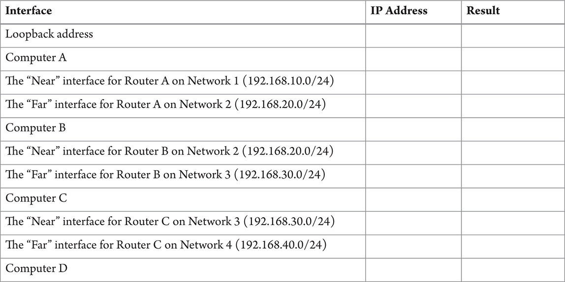
Step 2 After completing the configuration in Step 1, log on to a computer on Network 1. Use the ping utility to verify connectivity with the following addresses:
Since you may be using SOHO wireless routers for this lab exercise, the Internet (WAN) interface may actually have an entry that configures the gateway address for that segment. If your configuration uses the preceding table, where each LAN interface is the “Near” interface and each WAN interface is the “Far” interface, this effectively creates a routing table entry for this interface. When you ping from a computer on Network 1, the partial routing table on each of the routers may allow packets to complete additional hops.
To fully test connectivity, log on to a computer on Network 4 (possibly Computer D), open a command prompt, and ping Computer A. What are the results?
![]()
Step 3 In Step 2, what do you think contributed to some of the connections not being able to communicate?
![]()
![]()
Step 4 In the following steps you will enable one of the dynamic routing protocols (RIP) to automatically configure the routing tables on each router. This will facilitate the communication of computers on all four networks. First, you should familiarize yourself with the various dynamic routing protocols, types, and features, completing the following table:
![]() Cross-Reference
Cross-Reference
To further study dynamic routing protocols, launch your favorite Web browser and conduct a search on any of the protocols in the following table. You will find a wealth of information, much of it beyond the scope of the CompTIA Network+ requirements, but good to know for a competent network tech.
Excellent additional information regarding the various dynamic routing protocols may also be found in the “Dynamic Routing” section in Chapter 8 of the Mike Meyers’ CompTIA Network+ Guide to Managing and Troubleshooting Networks textbook.

Step 5 Starting with Router A, launch the setup utility and find the advanced routing settings. Before you change any of the settings, show the routing table. Refer back to Figure 8-3 in Lab Exercise 8.02 for an example of a default static routing table. Record the results in the following table:

You may notice that the table has only information on Networks 1 and 2. There is no information on how packets travel to Network 3 or Network 4. How can this situation be remedied?
![]()
![]()
Step 6 Now close the Routing Table information and enable a dynamic routing protocol, like RIP or OSPF. Save your changes. Repeat this step on both Router B and Router C.
Wait a minute or so to allow convergence of the routing tables, and then on Router A, launch the setup utility once again. Find the routing table. See Figure 8-7.

FIGURE 8-7 Routing table for Router A after implementing RIP
Record the results in the following table:

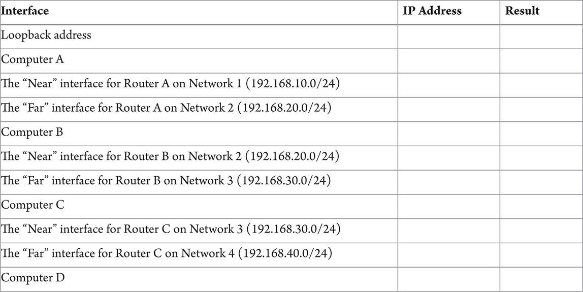
Step 7 Log on to Computer A on Network 1. Use the ping utility to verify connectivity with the following addresses:
To fully test connectivity, log on to a computer on Network 4 (maybe Computer D), open a command prompt, and ping Computer A. What are the results?
![]()
![]()
Step 8 You’re going to finish up this lab exercise with another TCP/IP utility known as traceroute (tracert in Windows). Tracert will allow you to record the number of “hops” or routers a packet has to pass through to get from a source computer to a destination computer (usually on a far-removed remote network).
Log on to Computer A and open a command prompt. At the command prompt, type tracert 192.168.40.XX, where XX is the address of your computer on Network 4. See Figure 8-8. Record the results in the following space:
![]()
![]()

FIGURE 8-8 Tracert from Computer A to Computer D
Lab Analysis
1. Joey has just manually edited the routing table on an internal Cisco 2651 router. He knows that these routes will remain fairly constant but wants to understand how you would configure routers on the Internet where routes change all the time. Explain to Joey the concept of dynamic routing and why it is so important for the Internet.
2. Ankush has been working with some routers and he keeps hearing the term “NAT overload.” He is concerned that this may be something that could restrict network bandwidth or even damage the router. What can you tell Ankush about NAT overload that will ease his concerns?
3. Bryan has just installed two new internal routers to configure separate networks for the marketing department and the sales department of his organization. Now the sales team is having trouble reaching the Internet. Using ping, what troubleshooting sequence should Bryan follow to determine where the connectivity issues are located?
4. Tova would like to see an example of a routing table but currently does not have access to a router. Show Tova how to use the route print command on any Windows computer and record some of the entries listed in the routing table.
5. Maurice has heard you mention the terms “distance vector” and “link state” when you were discussing dynamic routing protocols. He would like you to explain the difference between these two types of dynamic routing protocols in more detail.
Key Term Quiz
Use the vocabulary terms from the list below to complete the sentences that follow.
convergence
Open Shortest Path First (OSPF)
Port Address Translation (PAT)
Routing Information Protocol
tracert
1. _______________ enables the use of one public address for a network of private addresses that connect to the Internet. This version is often referred to as NAT overload.
2. The original routing protocol used was _______________.
3. The _______________ dynamic routing protocol uses Link State Advertisements.
4. The command-line utility that allows you to follow the path that a packet takes as it travels over networks and through routers is _______________.
5. _______________ is the point when all of the routers have used a dynamic protocol and all of the routing tables on all of the routers are up to date.