
CHAPTER 4
Software for Medical Systems
1. Introduction
Safety has long been a prominent concern with food, drugs, and devices. Medical devices are regulated by government in every important economy in the world. With the invention of the computer and the ability to embed computers and software in devices, it was only natural that software would become important in medicine. Sometimes the software is a medical device, such as image processing software making a breast cancer diagnosis from a mammogram would be. As software has gained more functionality and touched safety, such as in software systems that keep patients alive, regulatory bodies worldwide have gradually come to realize the importance of regulating software and its construction as well as the more traditional scope of regulating manufacturing processes.
The Food and Drug Administration (FDA), part of the Department of Health and Human Services, is the U.S. government agency with authority over the safety of food, drugs, medical devices, and radiation-producing equipment. To market any medical device or drug in the United States, you must have the approval of the FDA. The rest of the world has similar policies restricting their markets.
The eventual measurement of quality is success in the marketplace. Complex factors are at play in any economy, but by and large if a product meets customer needs they will buy it, and it will win out over its competitors. But this is a lengthy process—the product could spend years in the market and injure many people before it becomes evident that the rewards are not worth the risk. In the 1960s, thalidomide was thought safe and prescribed as an anti-nausea drug. Unfortunately, it was realized too late that if taken at a certain stage of pregnancy, it would cause birth defects. The objective of the regulatory environment is to prevent such disasters before they happen.
The governing law for current good manufacturing practices (cGMP) is found in Section 520 of the Food, Drug and Cosmetic Act. The FDA regulations are a nonprescriptive quality process. The actual regulation derived from the law is not very long. This results in the virtue of comprehensiveness but the vice of generality. Many paths can meet the same goal.
Because the eventual quality of a product is so hard to measure, takes too long, and is too risky, many quality programs do the next best thing, which is to audit compliance to the written policies. What the FDA expects is something similar. To the FDA, you are the experts in your device and your quality programs. Writing down the procedures is necessary—it is assumed that you know best what the procedures should be—but it is essential that you comply with your written procedures. At the same time, the methods cannot be too far off the beaten path, because then you will have to explain how they result in the same safety and effectiveness as standard practices in the rest of the safety-critical industry.
In the wake of political waves seeking to reduce regulation in the U.S. economy, the FDA promises to consider the “least burdensome approach in all areas of medical device regulation” [1]. Companies are free to adopt any policies they wish, but it is still contingent on them to establish with the FDA that the approaches they take will result in a product with adequate safeguards and quality. In practice, few companies are willing to accept the business risk of having their product launch locked up in a regulatory approval cycle.
The actual process for gaining regulatory approval in the United States is known as a premarket submission. Companies prepare documentation about the device, its software, the verification and validation activities, and the labeling that goes with the device. One aspect significant about the labeling is the claims for the device, that is, the conditions under which the device should be used, the types of patients and their illnesses that it should be used with, and the outcomes that should be expected. The claims are central to the regulatory process and the FDA thought process. These formulate customer needs and intended use. The standard is high; any company wishing to sell a device that is supposed to make people healthier must be able to prove it through scientific means. This notion of scientific proof underlies what the regulatory bodies are requesting and why they ask firms to do certain things.
Premarket submission must necessarily be late in the product development process, since the company will be documenting what the product can do. Part of this is to submit the product verification and validation documentation and also to perform the final design review, which occurs when the product design moves from development to manufacturing. The last thing a business could want is to have a product ready to manufacture and sell but held up by the approval process. The effect of this is to make companies conservative in their approach to quality programs so as to avoid a lengthy dialog with the FDA.
Rather like getting a legal opinion, in which the lawyer will only speak to the likelihood of an outcome from a court and cannot predict the final result, the FDA will not tell you beforehand which contents of a submission would be acceptable. FDA spokespersons want to avoid being in the position of having suggested that a method would be compliant before actually seeing the results.
This presents a challenge to the engineer developing software for a medical device, because the specifics of the methods for software construction are not spelled out. I will have more to say about this later, but the rigor of the methods and the amount of documentation required also varies with the “level of concern” for the safety of the software. Many of the methods described elsewhere in this volume are also appropriate for medical devices, and will be found acceptable to the medical regulatory bodies. This chapter hopes to inform the reader of methods the author has found that result in high-quality software and establish that quality to the regulatory bodies.
After all, it is not as if we are trying to get away with something. We all want software that works, software that—in the words of the FDA—is “fit for its intended purpose and meets customer needs.” We are obliged to build safe devices. In part, this is an ethical issue—as good engineers, we don’t want our devices to hurt anybody. But safety is also important to the business because of potential product liability. Practices that will result in the highest-quality software will also be acceptable to the regulatory bodies. For software development, aside from the level of documentation, there are not many practices required by the regulatory bodies over and above what engineers should be doing anyway.
Approaching regulatory bodies in an adversarial relationship is not helpful. They are a fact of life in modern economies; whether we like it or not, they serve a valuable function. Without regulations, markets will engage in a race to the bottom. Even if a company wants to be ethical, they will not remain competitive if their competitors are allowed to cut corners. Regulation establishes a floor for behavior beneath which companies cannot go.
1.1. Verification and Validation
Software verification and validation (V&V) forms a large part of the scope of software development for medical devices. Loosely, V&V is the activity of establishing that the software does what is intended. Often in informal usage, the words “verification and validation” are interchangeable or even redundant. Over the years a type of clarity has emerged, but one could still dispute where the line is drawn between the two.
The FDA definition of software validation is “confirmation . . . that software specifications conform to user needs and intended uses.” The phrases “user needs” and “intended uses” are commonplace in the FDA guidance documents. The FDA definition is related to the principle of showing effectiveness: not only did you accomplish what you set out to do, but your actions were the right thing to do. In other words, what you built met user needs.
Verification has a narrower definition. It is the act of demonstrating that design outputs match design inputs. The FDA sees software development (or any engineering development for that matter—see the discussion about design control in Section 3) as a step-wise refinement of project artifacts until development achieves the final deliverable, executable code. Each step starts with design input. The design is further refined, and the result is the design output. So, for example, one phase would be software coding. Coding starts with the software design as the design input. (The software design itself was the design output of the design phase.) Engineers then write the code that satisfies the design. Verification activities would be anything you did to verify that the code fulfills the intent of the design. This might be demonstration, such as dynamic testing. It might be a code review or inspection, in which the team examines the code and the design and ensures that the code implements the design, or that the design is changed to reflect the realities of the actual implementation. Activities performed in the normal course of software development such as requirements reviews, design reviews, unit testing, static tests, and build audits are all examples of verification.
Once you have passed through all the phases of development, the sum total of verification activities conducted at each phase sustain the conclusion that the software is validated. Verification comprises the individual steps, whereas validation is the sum of the whole.
Hence it is a bit mistaken to think that software validation is something that is done—or can be done—at the end of a project. To meet the standards expected by the regulatory bodies, the software will have had to be built with thorough verification activities right from the start. For this reason, it is difficult to subcontract software, because the subcontractor would have to satisfy regulatory requirements just as if you were implementing the development in house. So the problem becomes one of subcontractor management to regulatory standards. (This is part of the subject of the use of off-the-shelf or third-party software, about which I have more to say later on.)
Example 4.1 Precisely Wrong
While not a software failure, the development of the Hubble space telescope is a stellar example of the difference between validation and verification. The instrument had a troubled history—it was seriously behind schedule, and then was further delayed by holdups in the Space Shuttle program. When NASA finally flew the Hubble, they discovered that the mirror was wrong and could not focus [2].
Now this mirror is one of the most precise objects ever created. It was polished to within 10 nanometers—that is to say, 100 atom diameters—of its specification. This is 4 parts per billion in a 2.4-m mechanical structure. Yet when it made it to space, it didn’t work.
It turned out that a mistake had been made during its manufacture. A reference tool to establish the aspherical form of the mirror had been mismeasured and put in the wrong place. So when the technicians polished the mirror to within 100 atom diameters of precision, they polished it wrong. In other words, the mirror matched its verification—the output matched the input to an amazing degree. But the input was wrong, and the mirror failed at its primary purpose—to take clear pictures of the universe. This is a failure in validation.
(The NASA report [2] is interesting reading for the commonplace failures in the quality system that allowed the mistake to occur. Among those that also apply to software are ignoring the evidence when the system did not go together right, relying on a single measurement, failing to follow the quality plan, having QA people report to the project manger instead of being independent, and failing to specify the expected result, so that inexperienced personnel were unable to tell that something was amiss. I am happy to report that in later missions to the Hubble, astronauts were able to retrofit a focus adjustment device that allowed the telescope to take some of the most spectacular pictures of all time.)
To sum up:
• Verification is showing that you did what you intended to do.
• Validation is showing that what you did was the right thing to do.
What I have described is the meaning of verification and validation at the system level. Confusion on the part of some readers about the definition of verification and validation results from the FDA itself, in its description of software validation in the guidance document. I believe the FDA has overloaded the definition. There is validation, by which the FDA writers mean system validation as I have just described. There is also software validation, which is the sum total of verification activities—the construction of software according to software development policies. Technically, the definition for software validation is the same as any other kind of validation—the software conforms to “user needs and intended uses.” It is just that, in this case, the “user” is the rest of the system. If the software complies with its requirements, it has satisfied its “user’s needs.” Hence one could call, with complete legitimacy, the document with the tests in which you demonstrate that the software meets its requirements the software validation protocol. In fact, at a recent conference devoted to the development of medical device software, I informally polled the audience as to what was called the test protocol which established that the software meets its requirements. Half called it software validation, and the other half called it software verification.
1.2. Life Cycle Model
While the FDA recognizes that “[t]here are a variety of life cycle models, such as . . . waterfall, spiral, evolutionary, incremental” [3], their methods for documenting the software development process assume a waterfall model. This makes sense; the waterfall model may not be accurate, but it is a useful method for describing the deliverables and the activities that occur during software development. (As they say, “All models are wrong; some models are useful.”) I will follow the same practice, partly for reasons of modeling my presentation after the FDA and ANSI methods, but also because the waterfall is a useful way to discuss process. To refresh the reader, the waterfall model is the classical software development life cycle. (See Fig. 4.1.) Software development begins with vague customer needs and wants. These are formalized into requirements during the requirements analysis phase. This is input to the architectural design phase, where the structure of the software is created. With a software architecture in hand, engineers next develop the detailed design. Once all the designs are known, class definitions complete, methods named and prototyped in pseudo code, and a data dictionary written, the engineers can begin the coding phase. After the code is complete, the software enters the test phase, and once the unit, integration, and software system testing is concluded, the software is deployed for use by the customer. After that, it is in the maintenance phase. This development sequence is represented by the light-colored arrows leading to the right in the diagram.

Figure 4.1: Waterfall model of the software life cycle.
The trouble with the waterfall model is that it does not match the reality of the way that systems in general and software in particular is developed. It is rarely possible to define requirements in sufficient detail up front, leave them alone while the team develops the design, and then put all that away and actually start writing code.
After all, requirements originate in the vague wishes of the customers; many things they can imagine or hope for cannot be done. We are constrained by time, resources, technology, competitive intellectual property, and sometimes even by the laws of physics. Moreover, who can imagine that technology, our knowledge, or the marketplace will stay still while we spend months in requirements analysis?
In my experience, we often do not know what we can build until we try to build it. Construction is the real test of requirements. For a software life cycle to have any hope of reflecting reality, it must acknowledge the iterative nature of development. Indeed, more recent descriptions of the waterfall model show backward-pointing arrows between the phases, as you can see in the diagram. The drawing looks complex because you can return to any of the previous phases at any time.
Moreover, the phases are not always that distinct. Requirements sometimes shade into design, and vice versa. For example, if I am writing a custom interface between an embedded controller and a Graphical User Interface running on a laptop, I have quite a bit of design freedom in what the data exchange looks like. But once decided upon, if one or the other components doesn’t precisely comply, the interface won’t work. So is this design or requirements? It depends on your point of view and what you need it for at the moment.
The regulatory bodies allow that you are not restricted to a waterfall model; you are free to choose a different life cycle model. “Medical device software may be produced using any of these or other models, as long as adequate risk management activities and feedback processes are incorporated into the model selected” [3]. So, the risk management, feedback, and quality assurance activities are the keys to being able to assert that the software is valid, not the technical details of the order in which all of this was accomplished.
More modern agile approaches that recognize and take advantage of the naturally iterative unfolding of software development are the ones more likely to succeed. Develop requirements in layers of gradually increasing detail to get an idea of the scope of the project. This enables negotiating the trade-off of features, time, and resources before investing in a huge amount of detailed analysis. Perform an architectural design to understand the responsibilities of subsystems and the way that project task partitioning will allocate across the team. Then implement in stages.
The FDA has been tasked by Congress to consider the “least burdensome approach in all areas of medical device regulation” [1]. They will consider alternatives, such as a process like extreme programming (XP), which de-emphasizes formal requirements analysis and design in favor of user stories. It becomes a function of the level of concern of the software; such methods might be appropriate if there is no risk of harm from the software system. However, when the level of concern is moderate or major, there will be the expectation that methods of sufficient rigor were used to ensure that risk management activities were carried out.
2. The Medical Regulatory Environment
The FDA is the regulatory body in the United States with oversight of medical devices, among other things. Given that the U.S. medical market is a large part of the world’s medical market, medical device manufacturers seeking maximum markets will be interacting with the FDA.
The worldwide standardization body is International Organization for Standardization, or ISO [4]. The name “ISO” is not actually an acronym for anything. It is instead derived from isos, the Greek word for “equal,” as in “isosceles triangle,” and reflects the organization’s aim to equalize standards between countries. More than 150 nations are members, including all of the developed countries, so it is truly international.
Closely related to the ISO is the International Electrotechnical Commission (IEC); in fact, the two have published many standards together. As indicated by the name, IEC is specific to electrical and electronic devices. ISO is more concerned with quality systems for a broad range of products, whereas the IEC has standards for particular devices. (The IEC has a standard for “rumble measurement on vinyl disc turntables,” for example.)
Example 4.2 Guidance Documents
The FDA has a very good website, www.fda.gov, with many useful documents concerning medical device development in general and software for medical systems in particular. The most useful of these are the guidance documents, which serve to further explain the meaning of the regulations.
General principles of software validation. Final guidance for industry and FDA staff. January 11, 2002. Available at: www.fda.gov/MedicalDevices/ |
This is the most important for software development. If you read none of the other guidance documents, you should still read this one. |
Design control guidance for medical device manufacturers. March 11, 1997. Available at: www.fda.gov/MedicalDevices/ |
This document provides detail about the design control process itself, which is of larger scope than just software development. It is a description of good engineering practices that the FDA expects to be followed in the development of any medical device. Software development has to follow the same guidelines, as well as further specialized activities. |
Guidance for the content of premarket submissions for software contained in medical devices. May 11, 2005. Available at: www.fda.gov/MedicalDevices/ |
This document contains the criteria for establishing the level of concern of the software under development. It also describes the documentation necessary for the premarket submission, not just the list of documents but the type of content that they should contain. This will be important if you are responsible for putting together the software documentation for the premarket submission. |
Guidance for industry, FDA reviewers and compliance on off-the-shelf software use in medical devices. September 9, 1999. Available at: www.fda.gov/MedicalDevices/ |
This document tells you what the FDA expects you to do if you use third-party software in your medical device. It also has the most thorough discussion of software hazard analysis among the guidance documents. |
ANSI/AAMI/IEC 62304:2006. Medical device software—Software life-cycle processes. Available from the webstore at www.iso.org/iso/store.htm. |
This is the official international standard. It restates much of the information in the FDA guidance documents, but is crisper and less subject to interpretation. This is a valuable addition to the FDA documents, but does require purchase. |
IEC Medical Standards
The standards important in the medical world begin with IEC 60601:
• IEC 60601-1 Medical electrical equipment—Part 1: General requirements for safety.
• IEC 60601-1-1 Medical electrical equipment—Part 1-1: General requirements for safety—collateral standard: Safety requirements for medical electrical system.
• IEC 60601-1-2 Medical electrical equipment—Part 1-2: General requirements for safety—Section 2: Collateral standard: electromagnetic compatibility—requirements and tests.
• IEC 60601-1-4 Medical electrical equipment—Part 1-4: General requirements for safety—collateral standard: programmable electrical medical systems.
• IEC 60601-1-8 Medical electrical equipment—Part 1-8: General requirements for safety—collateral standard: general requirements, tests, and guidance for alarm systems in medical electrical equipment and medical electrical systems. First edition in August 2003.
• IEC 60601-1-9 Medical electrical equipment—Part 1-9: General requirements for basic safety and essential performance—Collateral standard: requirements for environmentally conscious design. First edition in July 2007.
These are mostly hardware standards that your device would need to comply with in general. IEC 60601-1-4 is the relevant standard for devices containing microprocessors. IEC 60601-1-8 may also be relevant if your software or device has alarms. This document spells out international standards for physical features of alarms, such as the loudness and frequency characteristics of an audible alarm, its cadence for different alarm priorities, and the colors to use for LEDs.
Other IEC standards would come into play if your product used components from the list of IEC standards. For example, if your device used a lithium battery, you would need to comply with IEC 60086-4 Primary batteries—Part 4: Safety of lithium batteries.
Safety Laboratory Markings
Safety markings, such as the UL, CSA, and CE marks, are much more relevant to overall electrical system safety than to software concerns. Nevertheless, if you are producing an electrical product, some form of a safety mark is required by almost all countries. Underwriters Laboratory (UL) is preferred in the United States, CSA is the Canadian standard, and the CE mark is required for EU countries.
UL is largely a testing standard. The CE mark, on the other hand, can be obtained through documenting a quality process. It is not necessary to have ISO 9000 certification to get a CE mark, but if you do, you will have completed 80% of the effort for getting the mark [5].
One difference between the CE mark and the FDA is that it is sufficient to show that a product is safe for the CE mark. The FDA creates a greater burden of proof by requiring that the product also be shown to be effective; in other words, that using the product results in some benefit to the user. This sometimes results in products being released in Europe before the United States, because effectiveness is much harder to demonstrate.
Approval for the CE is similar to ISO certification. You find (and pay) a notified body (such as TUV or BSI) to represent you to the competent authority—a representative arm of the EU member-state that monitors the activities of the notified bodies. This body will assess your product and company in much the same way that the FDA would assess it, with greater scrutiny accruing to higher-risk devices. The same kinds of testing and design documentation would be suitable for both.
Worldwide regulatory bodies embarked upon a major effort in the 1990s to harmonize medical device regulatory requirements. This has taken the form of the Global Harmonization Task Force (GHTF); it includes “representatives of the Canadian Ministry of Health and Welfare; the Japanese Ministry of Health and Welfare; FDA; industry members from the European Union, Australia, Canada, Japan, and the United States, and a few delegates from observing countries” [6]. There are four subgroups; the task force working on harmonizing quality-system requirements has had the most success.
Many countries defer to ISO standards for quality systems and IEC standards for safety. The regulatory bodies have established cross-approval processes, so generally what has been approved by one agency is acceptable to the other, with perhaps some tweaking. For example, the FDA requires a risk analysis but does not specify the method; the European agencies expect the risk analysis to be conducted per ISO 14971. Following the precepts of ISO 14971 is completely acceptable to the FDA. Generally then, since you know you will need to follow ISO 14971 for Europe, you might as well use the same analysis and structure to satisfy the FDA. “ISO 9001 is the most comprehensive because it covers design, production, servicing, and corrective/preventive activities. The FDA GMP requirements are slightly more extensive because they include extensive coverage of labeling, [sic] and complaint handling” [7].
There are a couple of significant reasons the FDA regulations are still separate from the ISO standards. In the first place, the FDA regulations and guidance documents are free. The ISO/ANSI/IEC documents are protected by copyright and require purchase, typically around $100. Charging for the standards is even more inconvenient than it seems. A full set is not cheap, and, although they are available as electronic documents, you cannot create more than one copy. A company would prefer, of course, to share them to lower the cost, but they can’t just print them whenever someone needs to consult a copy.
The second issue is that “FDA does not believe that ISO 9000:1994 alone is sufficient to adequately protect the public health. . . . Through the many years of experience enforcing and evaluating compliance with the original CGMP regulation, FDA has found that it is necessary to clearly spell out its expectations” [8]. This is because the FDA sees itself as more of an enforcement agency than ISO seems to be. Thus, the FDA wants to define the practices that its staff expects to see, not just recommend good practice.
In the next section, I provide an overview of quality systems from the perspective of both FDA regulations and ISO simultaneously because there is much overlap. At the same time, this provides an opportunity to point out the ways that they differ. Details of the quality system and the submission process are really the bailiwick of a company’s regulatory compliance personnel. However, there are occasions when the quality system interfaces to software development, so it is useful to know the regulatory context in which a medical manufacturer must operate.
2.1. Worldwide Quality System Requirements
The actual regulations for medical manufacturers doing business in the United States are codified in U.S. 21 Code of Federal Regulations (CFR) 820, known as the QSR (for quality systems regulations). The ISO general quality system requirements are described in ISO 9001:2001. There is a supplement to the general standard in ISO 13485:2003, which comprise additional requirements for medical devices. Together, these two international standards are equivalent to the QSR. There are no extra requirements in ISO 13485 that have relevance to design engineers, or to software engineers in particular, that have not already been covered by the FDA’s QSR.
The regulations are very high-level requirements that medical manufacturers must implement in order to have satisfactory quality systems. Many of these requirements are specific to manufacturing processes, such as device configuration management, documentation control, process control, and material handling. Developers of medical device software will be only indirectly concerned with many of these policies, although the software development process has to fit into the general scheme. Of greatest interest to software engineers is §820.30, Design Control (Subpart C).
Most of this chapter is focused on design control and its application to medical software development. But first I wish to briefly cover general principles of the regulations for medical manufacturers and their interface to software development. These are the sorts of practices that any medical manufacturer will have to follow.
The general policies are known as good manufacturing practices, or GMP. (Since this has been revised in 1996, the current policies are known as cGMP for current good manufacturing practices.) In other words, the QSR codifies cGMP. These are principles of mature product development and manufacturing firms; while medical manufacturers must comply, most manufacturers would benefit from following these practices, for they by and large make sense for manufacturing quality products.
The QSR and the ISO standard cover much the same ground, but the organization of the standards differs slightly. I will use the organization of the QSR, summarizing the policies of both organizations in the following sections.
2.2. Subpart A: General Provisions
The first section in both documents is an introduction that covers scope and definitions, plus some legal information. The applicability of the QSR is “the design, manufacture, packaging, labeling, storage, installation, and servicing of all finished [medical] devices intended for human use” [8]. “Finished” means that it does not apply to companies which manufacture parts that go into a finished device, but they are nevertheless encouraged to follow the same guidelines, where appropriate.
2.3. Subpart B: Quality System Requirements
This part of the QSR and the ISO standard cover organizational principles. Any company that wishes to manufacture medical devices must establish a quality system. The term “establish” has special meaning to the FDA—it means define, document, and implement. The documentation step is important. Companies must document and follow their processes.
The quality system must state a quality policy, and the company has to have the organization to support the quality system. This includes trained personnel, with sufficient time to do the work. There needs to be enough time in the production schedule to allow for inspection, testing, and verification. The quality organization includes an executive to oversee the quality system. One of the executive’s responsibilities is management review. The FDA is more specific and has more details about management review of the quality system than ISO. The FDA encourages an internal review to evaluate compliance, but staff will not ask to see the results under normal circumstances, in order not to discourage forthright reports. One part of review is internal audits of the quality system. Normally, these would not be shown to the FDA. ISO-notified bodies such as the TUV are less adversarial, and can ask to see internal audits, since they are seeking to work with the manufacturer to create compliance.
Both QSR and ISO require the establishment of a quality plan. The guidance from ISO is much more specific; the FDA in this case accepts the ISO standards. This is a case where ISO goes further than FDA and the FDA finds that completely acceptable. In another case, personnel, the FDA goes further than ISO. The FDA specifically instructs that personnel who build or test the device be made aware of defects that may occur if they don’t do their jobs right, or the types of error they may see so as to be on the lookout for quality problems.
2.4. Subpart C—Design Controls
The next part of the QSR, Subpart C, concerns design controls. This is the most pertinent part of the regulation for software engineers. In fact, the point of this chapter is to explain how a software development process can be designed to comply with Subpart C. It deserves a section of its own, so discussion of design controls appears in a subsequent expanded section, and in the meantime I press on with an overview of cGMP.
2.5. Subpart D—Document Controls
Document control is an important function in any manufacturing organization: it is the principal method for controlling change. Controlling change is necessary because the reason for any change in a medical device must be understood. In some cases, the change has to be validated, that is to say, it is not sufficient to claim “new and improved”; you must actually be able to show “new and improved” with actual clinical data.
The purpose of document control is to collect all descriptive documents that say how to make a product. These are the drawings for how to make pieces of it, the vendor list of whom to buy components from, the bill of materials (BOM) that tells you how many of what to build the product, and the standard operating procedures (SOPs) that tell you how to manufacture it. The SOPs extend to describing the process for controlling the process, that is, the procedures to change the documents in document control, or other procedures having to do with the quality system itself.
Note: Software has its own set of SOPs that describe the software development process. These are an extension of the quality system SOPs.
Changes to the document set are often known as engineering change orders (ECOs). Various elaborate schemes for managing the ECO process exist, but they are beyond the scope of this chapter. There are electronic systems to manage documents as data elements in a database, complete with electronic signatures. They are expensive and complex, but convenient in many ways. If you are looking for one (or building your own), keep in mind the fact that, since they are part of the quality system, electronic document control systems must themselves be validated. See Section 6.1, Software of Unknown Provenance (SOUP), for guidelines of how conduct this validation. They must also comply with 21 CFR 11, Electronic Records; Electronic Signatures, which are policies to ensure the validity of electronic records.
The ultimate deliverable for document control is the device master record (DMR). This is the sum total of documentation that tells how to build the product. The goal would be to have enough detail (including capturing cultural knowledge, which would then no longer be cultural) that someone else could build the product from the documentation alone.
Document control is especially significant to the FDA since the documents support the ability to trace all of the materials that went into manufacturing a product. In the event of a product recall, the FDA would want to be able to trace all the concerned lot numbers so that deviating product could be sequestered or pulled from the market. You as the manufacturer would want to have enough detail retained about configurations to limit the extent of the recall.
2.5.1. The Interface of Software to Document Control
The interface among software development, software configuration management (SCM), and document control will vary with the business and the applications. Software has its own need for configuration management (see Section 3.11, Software Configuration Management Methods) that needs to accommodate a huge number of changes with a limited amount of overhead. Most of the time the ECO process is enormously more cumbersome than software development could use and still stay productive.
The way I’ve seen it work is for the interface between SCM and document control to be at very specific boundaries. For example, documents that are used outside the software group are good candidates for release to document control. The alphabet soup of development documents should be in document control—they define what the product does as much as the executable. Most documentation that will be included in the premarket submission will be in document control.
When software is a component in the medical device, the released software is treated as a virtual part under document control. It is given a part number and a place in the BOM. Revising the software requires an ECO.
If software is the medical device and your firm is not otherwise a manufacturer, other systems may work for you. It will, as always, be a function of the level of concern for the software. What is required is compliance with control methods. You have to be able to ensure that you know exactly what software configuration went into the device, and that a change cannot have occurred without proper approvals and validations, as necessary.
2.6. Subpart E—Purchasing Controls
Purchasing controls are procedures to make sure that purchased products conform to their specifications. The FDA is not regulating the component suppliers, so they explicitly require the device manufacturers to exercise control themselves. This mostly has to do with raw materials and components, and so on, but where it is important to software is that it also covers contractors and consultants, who may be providing software. It would also include off-the-shelf (OTS) software.
Firms who use contractors must document the selection of a contractor and why the contractor is able to perform the job. They must also define the control mechanisms they will use to ensure quality, and review the work of the contractor at intervals to confirm that requirements are being met. Finally, the contracting company must document and maintain quality records for acceptable contractors.
One form of the purchasing controls is in the data that the company uses to buy the specific items that will go into the medical device and the methods to ensure that what was delivered was what was agreed to. Purchasing controls like this would prevent something like the Chinese toy recall of 2007. For software, for instance, the purchase agreement would need to state which version of an OTS package was being used in the device.
The FDA regulations spell out that a supplier should notify the manufacturer of changes in the product they are providing so that the manufacturer has an opportunity to evaluate how the change may affect safety and effectiveness. They warn that suppliers who don’t notify the manufacturer may be unacceptable. ISO is slightly less strict in this regard, but ISO indicates that it is a good practice.
The degree to which you were to specify an exact version is a function of the safety or effectiveness of the finished device. For example, it may be possible to simply specify a generic version of Windows, such as Windows 2000 or XP. But because Windows comes in so many variants and installations, making testing each combination difficult or impossible, a generic specification is probably not suitable for the moderate or major level of concern, and may be unwise for minor-level-of-concern software.
2.7. Subpart F—Identification and Traceability
The purpose of identification is to prevent the use of the wrong component or material in manufacturing. The method to provide for this is to make each batch or unit traceable with a control number. For software, this implies version labels, although firmware could be identified with a part number on the program storage medium or board.
While it is not part of 21 CFR 820, the FDA also has regulations for tracking which devices go into which patients [9]. This is necessary so that if a problem is found in production, the manufacturer can find the products and warn the recipients or recall if needed. For example, Medtronic recently determined that some defibrillator leads were prone to fracture and issued a voluntary recall. By identifying the patients who had the leads, their doctors can plan to adjust the defibrillator settings at the next visit [10].
2.8. Subpart G—Production and Process Controls
Production and process controls are really a manufacturing subject. They comprise the methods that a manufacturer uses to make sure that the products they are making consistently meet specifications. The subpart covers manufacturing and inspection procedures, environmental control, cleanliness and personal practices of personnel, contamination control, building, and equipment.
Insofar as a manufacturer uses automated data processing systems for production or in the quality system, “it is necessary that software be validated to the extent possible to adequately ensure performance” [11]. This does not mean that you have to conduct software V&V to the extent that you would for product software. Often, source code and design documentation are unavailable. What you must do is confirm that the software meets your needs and is fit for the purpose you have in mind. This is a matter of determining your requirements for the OTS software and conducting black-box tests to verify “that it will perform as intended in its chosen application” [11]. You would not need to test every feature, but you would want to convince yourselves that the features important to correctly manufacturing or inspecting your device are working properly, or that you are using the device properly. For more about this, see Section 6.1.2, Third Party Validation.
2.9. Subpart H—Acceptance Activities, and Subpart I—Nonconforming Product
These subparts discuss receiving, in-process, and finished device acceptance testing and inspections. In an interesting difference between ISO and FDA, ISO allows release of product prior to full verification under an “urgent use provision,” provided that the manufacturer keeps track of it in case of a recall. The FDA does not permit urgent use; devices must have a completed set of final acceptance activities, including signed records, before release.
Presumably “urgent use” could include the release of beta software to a customer site to fix a serious problem, before the full software V&V had been completed. This would be allowed by ISO but is forbidden by FDA. To them, the advantage is not worth the risks.
If the inspection finds that a subcomponent, material, or product does not meet its specifications, the nonconforming product subpart deals with “the identification, documentation, evaluation, segregation, and disposition” [12] of such items, so that there is no danger of mixing it with released products. Generally, the nonconforming product must be specially tagged and kept in a protected area away from the acceptable product. The company must have a documented procedure for deciding what to do with the deviating items: reworked, accepted by concession, used in alternative applications, or scrapped. A nonconforming product accepted by concession must have a justification based on scientific evidence, signed by the person authorizing its use.
2.10. Subpart J—Corrective and Preventive Action
Methods to provide feedback when there have been problems are a part of any quality system. For the FDA, this is the corrective and preventive action process, also known as CAPA. The purpose is to identify root causes for quality problems and provide correctives so that they don’t happen again. This is risk based—problems deserve investigation equal to the significance and potential risk.
CAPA is a very serious matter to the FDA and other regulatory bodies; for one thing, it is subject to audit and almost always looked at by the auditor. It is a prime role belonging to the QA/RA (quality assurance/regulatory affairs) departments of a medical manufacturer. Any death associated with a device is relevant, even if caused by user error. This is because human factors should have been considered in the design of the device, and misuse is a failure of the human factors design. Manufacturers would be expected to evaluate whether a redesign or more cautions and warnings in the manuals are called for.
You could extend a software problem reporting process to cover all the issues that could occur in manufacturing a device and in handling customer complaints. Usually you would not want to; you don’t want to confound and overwhelm the quality data from the rest of the organization with minor software defects. At the same time, you don’t want to make the process of closing software defects so cumbersome that you discourage their reporting. The rigor for follow-through on a CAPA issue is often quite high, and CAPAs are supposed to be reviewed in the quality-system management review meeting. You may not wish to find yourself explaining to the CEO what a race condition is and how you verified that you had fixed it. (A race condition occurs when operations can occur in any order but must be done in a certain sequence to be successful.)
A tiered system is likely best, where only software defects discovered after release of the software go into the CAPA system. These defects would be duplicated into the CAPA system if they were determined to be of threshold severity; customer complaints or other quality issues needing a software change would go into the software problem reporting system to inform the software team of actions that need to be taken.
2.11. Subpart K—Labeling and Packaging Control
The one thing to note for software in this section is the special meaning of “labeling” and its importance to the FDA. This is not just the manufacturer’s label with the model and serial number of the device. Labeling is any textual or graphical material that is shipped with or references the device. It includes the user’s manual, physician’s guide, instructions for use, container labels, and advertising brochures. The text on a screen or in a help system in a software-controlled device is labeling.
Labeling is also part of the premarket submission process. (The premarket process is further discussed later in this chapter.) You want to be careful that you don’t make claims in the use of the product that have not been validated through clinical use. While doctors, based on their own judgment, can use devices as they see fit, the manufacturer cannot make claims for therapy that are not backed up by science.
Labeling is also an area where the FDA differs slightly from ISO. The FDA requires an examination for accuracy of the labeling, and a record that includes the signature of the inspector, documented in the device history record. The FDA does this because its data show that, even with the rules, there have been numerous recalls because of labeling errors. ISO is not so strict; while you can retain label inspection records, you are not required to do so.
2.12. Subpart L—Handling, Storage, Distribution, and Installation
Now we are into a part of the regulation that is really more about issues related to manufacturing and distributing devices. This doesn’t have much to do with designing the products or the software that goes into them. Policies about handling, storage, and distribution are designed to make sure that devices are properly taken care of before they arrive in customer’s hands, and that only a qualified released product is shipped.
As for installation, the manufacturer must have directions for correct installation and must ship them with the device or make them readily available. These should include test procedures where appropriate. The installer is also required to maintain records, subject to audit, that show the installation was correct and the test procedures were followed. In another difference from the FDA, ISO does not address installation as a separate subject.
If the medical device requires an elaborate software installation, these requirements could be an issue. If the manufacturer performs the installation, it would have to keep records. Third parties can do the installation, but then are considered to be manufacturers, and are subject to their own record requirements. You would want to provide comprehensive installation instructions—it would not be sufficient to assume that the user would know to double-click setup.exe. You could also provide a signature form with instructions to document the installation and retain the record. You might need to provide a small validation to confirm that the software installed correctly, and have the users sign, date, and keep the form in their records. Hospital bioengineering departments are usually comfortable with this.
2.13. Subpart M—Records
This is an area where the FDA has much more to say than the ISO. The FDA requirements would fit under ISO—there is nothing inconsistent—but ISO is much less specific. So if you intend to market in the United States, you would need to comply with the detail the FDA describes. For this reason, I will summarize the FDA record-keeping policies.
There are five classifications for record files:
• Design/device history file (DHF)
• Device master record (DMR)
• Device history record (DHR)
• Quality system record (QSR)
• Complaint file
The DHF is not discussed in this section, but is nevertheless an important record, and second only in importance to the DMR for design engineers. I have more to say about this in Section 3, on design controls, since the DHF is really the documentation of the design history. These are the records of design reviews, technical reviews, verification activities, analysis, and testing that collect the history of the design. ISO has no specific requirement for a DHF.
Creating the DMR is the whole point of the design phase. It is the collection of drawings, specifications, production processes, quality assurance methods and acceptance criteria, labeling, and installation and servicing procedures. In other words, it is the set of documentation that tells a manufacturer how to build a device. These specifications must all be controlled documents under the document control procedures. Software specifications are explicitly included as a component of the DMR.
The DHR comprises the data for each particular device. This must identify each device or lot, the labeling, dates of manufacture, and the acceptance tests used to show that the device was manufactured according to the DMR.
The QSR is the set of SOPs, compliant with FDA regulations that are not specific to a particular device. These describe the quality system itself, and the practices, policies, and procedures used to ensure quality in the device and its manufacture. It is important to occasionally analyze the procedures to determine whether they are inadequate, incorrect, or excessive [7].
The complaint file is a much bigger deal for the FDA than for the ISO. In the ISO guidance document, it is merely referenced as an example of a type of system record. ISO 13485 extends this to a near-equivalent of FDA requirements.
The FDA specifies that each manufacturer will maintain a complaint file and establish “procedures for receiving, reviewing, and evaluating complaints by a formally designated unit” [13]. “Any complaint involving the possible failure of a device, labeling, or packaging to meet its specifications shall be reviewed, evaluated, and investigated. . . .” [13] (emphasis added). Even if you decide an investigation is not warranted—because it has been reported already, for instance—you must document why no investigation was made and who made that decision.
Medical care providers are required to report any death, serious injury, or gross malfunction to the FDA and the manufacturer. The manufacturer must determine whether the device failed to meet its specifications and how the device might have contributed to the adverse event. Beyond this, there is also a specific list of the data that the manufacturer must keep with respect to complaints.
A software defect could show up as a customer complaint (also sometimes known as a customer experience report, or CER). Normally you would want the complaint handling to be separate from your software problem reporting system, because of the formality required to deal with customer complaints. But expect the complaint file to be the origin of some of the defects in the software problem reporting system.
All of these records need to be carefully maintained, backed up where electronic, and made readily available to the FDA for inspection. You should keep records for the expected lifetime of the device, but not less than 2 years from date of release.
2.14. Subpart N—Servicing and Subpart O Statistical Techniques
Where servicing is required by the product, both FDA and ISO require documented service procedures and records. The FDA is more specific than ISO about exactly what data go into the service report.
Servicing is an opportunity to collect metrics on the process capability and product characteristics. Collecting statistics is a recommended good practice, but it is up to the manufacturer to decide its appropriateness.
2.15. Post-Market Activities
2.15.1. Audits
A key practice of quality systems in general is the conduct of audits. The purpose of an audit is to have an independent reviewer assess how well the organization is following its procedures and meeting its quality goals. Both FDA and ISO recommend internal audits, at least annually. For ISO, it is necessary to have an independent audit by the notified body in order to retain certification. These are audits that you pay for, so they tend to be more congenial than an FDA audit. They are reviewing your compliance and suggesting ways to help you better comply with the letter and spirit of the quality systems.
The FDA, on the other hand, is fulfilling its regulatory duty. FDA staff take a more adversarial, even suspicious, approach to protect public safety. They are less likely to give you the benefit of the doubt. Plus they have had many years of experience with product safety and failure, and have learned what kinds of practices may lead to injury. They are an enforcement agency and are not to be disregarded. They have badges.
They can look at the DHF and the change records. “The holder of a 510(k) must have design control documentation available for FDA review during a site inspection. In addition, any changes to the device specifications or manufacturing processes must be made in accordance with the Quality System regulation” [14].
As a software engineer, it is unlikely that you would have direct interaction with an auditor in all but the smallest of companies. It is usually the responsibility of the QA/RA part of the organization. Nevertheless, if it does come up, there are a few things to remember about handling an audit.
It is best to think of it as a kind of legal interaction. First of all, don’t offer information. Answer the questions they ask, but don’t volunteer more than they are asking for. It can provide an opportunity for them to dig further or suggest ways in which your organization is weak.
Second, just answer the questions factually. Don’t speculate or offer an opinion about how effective a process is or how well something works. Don’t guess. It is okay to say, “I don’t know” (although that may cause them to write you up for poor employee training).
Finally, and in a related vein, don’t get caught up in hypothetical questions. If they ask you what you would do in a certain situation that has not occurred, the best answer is, “We have not dealt with that.” If they press, the answer is, “We would follow the procedure.” You don’t need to stonewall or be a jerk, but you also don’t need to express your concerns. That’s their job.
3. Design Control Explained
3.1. Purpose of Design Control
The quality system regulation describes at a high level the process for developing customer needs into a marketable medical device. This process is found in Subpart C of 21 CFR 820 [15] for the United States. It is known as design controls to the FDA but goes by the singular design control in ISO Q9001, Section 4.4. It encompasses designing a new product and transferring that design to manufacturing. The objective of design control is to “increase the likelihood that the design transferred to production will translate into a device that is appropriate for its intended use” [16].
Design control is an outline of a new product development process and is general to all aspects of product development, mechanical and electrical, not just software development. The regulation itself is not very long—about 700 words—and not very specific. The software development process needs to fit into the overall process, but software will have extra phases and detail.
Almost all Class I medical devices are exempt from design control, unless they contain software. (For a discussion of device risk classes, see Section 5.7, Device Risk Classes.) Class II and Class III devices are always subject to design control. Since the purpose of this chapter is to discuss software for medical devices, any process we propose will be subject to the design control regulation because any software-controlled medical device is subject to design control.
The design control process is like the waterfall model for software development but even simpler (Fig. 4.2). There are four phases: design input, where the customer needs are determined and described in engineering language; device development, where the design is fleshed out, and the design process captured in the DHF; design output, where the final design is captured in the DMR; and production, where the device is repeatedly and reliably manufactured for sale. The transition between phases is always qualified by a design review.
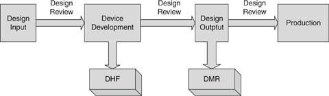
Figure 4.2: Design control process.
It is possible for a simple medical product with a handful of requirements to go through the design control process in a single phase of design input, device development, and design output. From the get-go, software has more phases, so it is only meaningful to discuss design input, device development, and design output as the boundaries between the phases in the waterfall model. One set of design outputs becomes design inputs to the next phase. Thus in a very high-level sense, software development follows the design control model, but sometimes people are confused because there is so much more detail in the software development process. The design control process was invented to encompass all kinds of projects. A simple project like the development of an extension to the application of a catheter (a new claim for what the catheter could do, with some minor changes) is something that might have a single design input/design output phase.
For more complex devices, this really becomes a stepwise refinement of specifications to more and more detail until the final device is fully specified. Once the team has reviewed the design input requirements and found them acceptable, for example, you can begin the iterative process of translating those requirements into a software architecture. Once the architecture is verified as a correct response to the high-level requirements, this output then becomes the input to the next phase of software design. “Each design input is converted into a new design output; each output is verified as conforming to its input; and it then becomes the design input for another step in the design process. In this manner, the design input requirements are translated into a device design conforming to those requirements.” [16]
I will first discuss design control as described in the regulation in the general sense in which it applies to product development as a whole. Further on, in Section 5, Software V&V in the Context of Design Control, I describe the way software development fits in to the design control process. (This is my own stepwise refinement of QSR → design control → software development process.)
In terms of the regulations, those who develop software to control a medical device “shall establish and maintain procedures to control the design of the device in order to make certain that specified design requirements are met” [17]. Notwithstanding language about the “least burdensome approach” and some freedom in selecting software-development life cycles, compliance to the design control regulations will probably look like a traditional, rigorous approach to the software development process, with a focus on documenting the process steps and holding reviews at each phase of development.
It is especially important that the design of software be carefully controlled. The FDA recognizes that the quality of software is not dependent on its manufacture, which is contrary to the case with physical devices. There is no process variability to duplicating software—its manufacture is usually trivial. What is critical is the quality of the construction in the first place.
Because it is so easy to change, some fall into the fallacy of thinking that software is easy to correct and thus does not require controls as stringent as the ones for hardware. The FDA holds the more sophisticated view that, “[i]n fact, the opposite is true. Because of its complexity, the development process for software should be even more tightly controlled than for hardware” [1]. Insofar as the goal of design control is to ensure that the design output meets customer needs and serves its intended purpose, controls are even more important. Software can more easily adapt to new knowledge about customer needs, which is a great strength, but the process must ensure that real needs continue to be met.
A feasibility study does not need to meet the requirements of design control, but when you have decided to produce a design, you will have to create a plan so that the device will meet the quality requirements. It is tempting to just develop the prototype, and then reverse engineer the design control into the project. This is not the best method. The FDA has found that “[u]nsafe and ineffective devices are often the result of informal development that does not ensure the proper establishment and assessment of design requirements that are necessary to develop a medical device that is safe and effective for the intended use of the device and that meets the needs of the user” [16, 18].
One final note: the FDA is prohibited by law from determining the safety or effectiveness of a device by looking at the design control procedures that a manufacturer uses—safety and effectiveness determination is the purpose of the premarket submission. However, they do audit the SOPs for an adequate implementation of design control. So the device could be safe and effective, but inadequate procedures could still land you in trouble.
3.2. Project Planning
The first step in design control is project planning. Project planning is necessary for the organization to determine where it is going, and even more important to have an idea what it might look like to arrive there. It is crucial to have the conception of what the project goals are, and what it means to meet customer needs and be fit for intended use.
It is not specified in the design control guidance, but I’ve always found it helpful if the project plan starts with a mission statement or vision of what accomplishing the project means. A mission statement is a description in 50 words or less of the goal of the project. GE HealthCare has a concept of CTQs—the list of features that are critical to quality. These are the features—no more than five or six—that the product must have to fulfill customer needs and achieve the product goals for the company.
The purpose of the project vision is to focus the development team on what needs to happen, and more important, on what does not need to happen. The essence of good design is deciding what to leave out. A strong vision statement can focus decisions when a room full of bright people start brainstorming all the things a product could do. Usually, doing everything in the world is not a very wise approach to medical product development. It takes longer, and delays the day when our products reach the market and start helping people. It adds to complexity, and higher complexity reduces reliability in devices that must be safe. And it drives engineers nuts.
It is not easy to write a good vision statement, and many are so meaningless that it may lead you to be cynical about the whole idea. They can end up as a mom-and-apple-pie statement that is hard to argue with. For example, a company could start a project to “build the world’s best word processor.” Unfortunately, that does not leave any basis for deciding what to leave out. Any idea that anybody comes up with must be included—we are trying to build the “best,” after all, and how can it be best if it doesn’t have every feature imaginable? But projects like this may never end, and even if they do, they are often late and cluttered with features that get in the way of the essential function.
Note: One way to screen out happy talk is to apply a test for information content. To do this, negate the statement and see if it is obviously false. So negate the original example, “We will not build the world’s best word processor.” Clearly, no one would set such a lousy goal.
A better vision would be to “build the word processor that allows writers to get words on paper in the easiest, fastest way.” Or “build the word processor that allows casual users to format the look of the document in the easiest way.” These have enough content that they communicate the decision about what the product is going to be and what it is not going to be.
A second purpose of planning is to reduce the number of false starts and distracted pathways. This is, of course, advantageous to the company; it is certainly not in the interest of the development organization to pay for development that will never be used. But it also enhances quality. Even though by its nature development will often be iterative, we don’t need to indulge more iterations than we have to. Change management is difficult and important to control, but the easiest way to control change is not to have any. Attention lags the tenth time you’ve done something, and errors creep into upstream documents when it is necessary to revise downstream documents in response to new knowledge.
Of course, there will always be new knowledge, and the last thing we want to do is ship the wrong product come hell or high water. No plan survives contact with reality, but that does not mean that planning is not useful.
Finally, the purpose of planning is to reduce the pressure to compromise quality when projects are behind schedule. The FDA recognizes that deadlines have contributed to defects introduced when designs were not carefully considered due to lack of time, and these defects have resulted in injury [16]. Project plans should emphasize accomplishing quality goals over calendar goals. Good plans let managers make supportable decisions when it is necessary to compromise the project to meet deadlines.
The amount of detail in the project plans is going to vary with organizational needs, the size and complexity of the project, the work habits and personalities of the team, and, as always, the level of concern of the device or software. It is not necessary to plan every last detail. In the FDA’s own words, “Each design control plan should be broad and complete rather than detailed and complete. The plan should include all major activities and assignments such as responsibility for developing and verifying the power supplies rather than detailing responsibility for selecting the power cords, fuseholders [sic] and transformers” [1].
It is important for the plan to describe the interfaces between the contributors and the stakeholders that have input to the design process. To be effective, the plan should establish the roles of the groups involved in the design and the information they share. A typical plan would include:
• Proposed quality practices
• Methods to assess quality
• Policies for record-keeping and documentation
• Sequence of events related to design.
3.3. Design Input
Once preliminary plans are formulated, the device design begins with the design input phase. The starting design input is the as-yet unformed user needs or amorphous marketing concepts. A vision statement will have gone a long way toward deciding what the product will be. The project vision statement, if you use one, will be the first formal description beginning to refine the vague wishes of customers into a product concept. With this, the task of the engineer is to turn the user needs into design input requirements with enough detail and formality that they can serve as input to subsequent phases in the development process.
A distinction that has caused me confusion is naming the phases. Design input is not a thing or deliverable, but a phase of the development process. It has inputs and deliverables (outputs), but they should not be confused with design input—what is really meant is the phase.
In the traditional software waterfall model, the design input phase maps to the requirements analysis phase. So the input is the customer needs and user requirements, and the output is the software requirements specification (SRS). From the project perspective, where design control is describing whole product development, not just software, the input to the design input phase is equivalent—customer needs. The output of the design input phase will vary with the complexity and nature of the project.
Projects of moderate complexity that involve both software and hardware have more elaborate needs for what has to happen in the design input phase. It is still requirements analysis, but now the requirements are for a more complex system containing elements of hardware and software that have to interact to satisfy the product requirements.
The output of the design input phase is design description documents. These documents define the product’s:
• Functional and performance characteristics
• Physical characteristics
• Safety and reliability requirements
• Environmental limits for safe use
• Applicable standards and regulatory requirements
• Labeling and packaging requirements
Human factors analysis and testing should be conducted and used as input to define the function and performance of both hardware and software, including testing the instructions for usability [19]. The specifications should be quantified whenever practical. Where that is difficult, the design document should identify the parts of the design that require further analysis and testing. The document should record any incomplete, ambiguous, or conflicting requirements and provide a mechanism for resolving them.
Developing the system design requirements document is often a function of a systems engineering group. Many organizations may not have the wherewithal to sustain an entire engineering department devoted to systems engineering, yet the systems engineering must occur. It is where the electrical engineers, mechanical engineers, and software engineers get together and allocate requirements to subsystems.
Often you have the design freedom to decide where best to implement a requirement. For example, if you had a requirement to make an alarm sound at multiple frequencies so that the aurally impaired stood a greater chance of hearing it, you could try to find a sound transducer that would produce the sound at the desired frequencies and loudness, or you could create sound waveforms in software in your main processor, or you could devote a special processor to it. Each has tradeoffs in product cost, development time, power usage, and so on. But if the process does not happen, it would be easy for a software development team to fail to schedule time to develop waveforms to output to a driver circuit that the hardware engineers had designed.
System engineering becomes especially important in the development of requirements around hazards. I’ll have more to say about the subject in Section 4 on risk management.
It can be difficult to collect all necessary and correct requirements during the design input phase. As Nancy Leveson has observed, “On many projects, requirements are not complete before software development begins. . . . To avoid costly redesign and recoding, the requirements specification and analysis should be as complete as possible as early as possible. Realistically, however, some of the analysis may need to be put off or redone as the software and system development proceeds” [20]. For this reason, write the system design requirements document so that it can change as issues are resolved and new knowledge gained. The document (or the design input process) should define what would trigger an update, and who is responsible. At the conclusion of the design input phase, the system design document is subject to design review and requires “the date and signatures of the individual(s) approving the requirements” [19].
The FDA realizes that “[a]s the physical design evolves, the specifications usually become more specific and more detailed” [21]. Nevertheless, if possible, the team should strive to get the upstream requirements analysis as correct as possible. As is commonly known, the later in the development process a defect is found, the more expensive it is to correct. (This is especially true for medical devices, which are subject to postmarket surveillance and complaint handling regulations, as explained in Section 2, The Medical Regulatory Environment.) Furthermore, correcting a defect later may have ramifications for the project as a whole. It is much easier to get it all right when thinking about it, especially for hazards, than to go back and reconstruct all the thinking that went on during the risk analysis. Often risks interact in complex ways; a superficially insignificant change in one subsystem may have influences on the rest of the system that are poorly understood.
At the same time, it is possible to spend almost unlimited time in analysis, contemplating behaviors and risk probabilities that cannot be known without some level of prototyping. Perhaps prototyping is needed before the design input phase is complete—even then, what you know about is a prototype and not necessarily the thing that will be built.
Better to not expect to resolve every to-be-determined (TBD) or think that you will capture every requirement. The first drafts of the requirements are documents useful for refining the project planning documents. It is beyond the scope of this chapter to discuss scheduling methods and project planning in depth. But generally what happens is a negotiation of the set of requirements—the features the product has—versus the time and resources available to develop them. During this negotiation it is vital to have a sense of what the requirements are and that is what I mean by the utility of the draft requirements as input to the project planning.
Stepwise refinement of the requirements will occur throughout the development of the project, but this will require effort to maintain consistency between the downstream documents and the upstream documents. Moreover, one of the deliverables at the end of the project is a traceability matrix (see below) in which you establish that all requirements have a corresponding test (and vice versa). So if you had discovered new requirements during development, you would want to be sure that they make their way back into the upstream documents.
One thing to make things easier is to resist tightening the bolts too early. A lot of this is just the use of standard good coding practices. Keep things decoupled. Use accessors and mutators to get at data so that the data itself can change. Keep the data abstraction at a high level. Use identifiers for constants; don’t use magic numbers. You can put off deciding a lot of things like thresholds because they will be easy to change in a solid software design. But you can’t put them off forever—sooner or later you will have to establish why something has one value and not another. While it can be easy to change in software, it can be difficult to validate that a change is justified. Changing the number may be trivial, but the validation of the value of the number is crucial. (Remember the Hubble example!) “The device specification will undergo changes and reviews as the device evolves. However, one goal of market research and initial design reviews is to establish complete device requirements and specifications that will minimize subsequent changes” [7].
There are several more things that I want to say here about requirements management.
You can use word processor–based documents and it will probably work for small projects. As project complexity increases, you would want to look at a requirements management database. This would let you view the requirements from different perspectives. For example, a system hazard analysis may want to view requirements from the perspective of which requirements are essential to the function of the device. But normally that is not the way to organize requirements as input to the design process—you would want related requirements close to each other. A requirements database would let you run reports to view the requirements in a narrative that made sense for the application at hand, without changing or repeating the requirements themselves. You can organize the requirements in different ways for different audiences.
Furthermore, establishing traceability from a database is much easier compared to tracing in word-processed documents. About the last thing most projects need when they are close to delivery is a bunch of time spent laboriously tracing requirements from narrative documents to test documents.
Next, normalize requirements. Try to describe a requirement only once, so that if it changes you have fewer places to have to change it. Use pointers to reference the associated requirements or requirements that are presented in greater detail. For example, you could define the values of constants in a source file and use that as the requirements specification. This will make you take care to supply good comments!
This is another spot where a database will help by letting you define a requirement only once, even though it may exist exactly as written in multiple downstream documents.
Normalizing requirements is complicated by the premarket submission process. You cannot assume that a reviewer will have access to all the documents, or the ability and time to understand your system. It is most helpful to reviewers if the documents in the review package can stand by themselves. This makes the documents repetitive: they become more comprehensible to your reviewers but more defect-prone to you. Again, a database would help to contain the boilerplate that can then be added to each document as needed.
A requirements database has enormous advantages, but don’t forget that you have to perform some level of SOUP validation. But overall it makes the system more resilient to change; change is necessary and inevitable, so installing a system that makes change management easier, less costly, and less likely to result in error is sure to be a good thing.
Requirements management is often so complex that there is a great temptation to wait until the system is built and then document the requirements that it fulfills. A retrospective method like this is not against the rules; indeed, with legacy projects it might be the only way to create the upstream documents at all. Nevertheless, it is not the best design approach and should be avoided if possible. What really needs to happen is that the product should be designed according to the principles of good engineering practices from the beginning.
3.4. Design Output
The design output is the response to the design input. The deliverables that constitute the design output are part of the project planning process, the nature of the project, and the standard operating practices of your company. “The total finished design output consists of the device, its labeling and packaging, and the DMR” [22]. The DMR, or device master record, the complete set of documentation that describes how to build the product. Hence it would consist of things like schematics, assembly drawings, BOM, work instructions, source control drawings that describe how to buy parts, and test specifications for manufacturing and inspecting the device and its subcomponents. The DMR is subject to design review, and the date and signature of any individuals who approve the output must be documented.
The general rule is that design output is the deliverable of a design task in the development planning document. (This is another reason why the planning is important.) For software, the equivalent type of design output is typically source code, the executable, operator’s manuals, and documentation of verification activities. One principal verification activity is to review the design output against the design input to confirm that the output matches the input.
In other words, the software implements the requirements. This is usually captured in an acceptance test, software validation protocol, or software system test protocol to demonstrate that the requirements are met.
3.5. Design Review
The design review is a key practice of the design control process. Design reviews should occur at major milestones, such as passage between phases of the design control process. To the FDA, “Design review means a documented, comprehensive, systematic examination of a design to evaluate the adequacy of the design requirements, to evaluate the capability of the design to meet these requirements, and to identify problems” [16]. The purpose of design review is to:
• Assess the quality of the design
• Provide feedback to the designers on possible problems
• Assess progress toward completion of the project to determine if passage to the next stage of development is warranted
When a device is available from initial manufacturing production, the development team will perform a final design review to confirm that the device meets the design specifications as described in the DMR. This is the most important of the design reviews, and it is essential that the review be against a product from pilot production, because the purpose of the final design review is to establish that the manufacturing arm of the organization can in fact routinely manufacture the product that the engineers designed.
Design review will be a formal meeting. The authors of the work product or subsystem designers should be present, as well as the designers of interfacing subsystems when applicable. It is important that at least one reviewer be disinterested, that is to say, should not have direct responsibility for the work product under review, to avoid conflict of interest.
The output of the review should be a list of action items. While it is possible that such a fine job was done that there are no issues to resolve, the FDA is wise enough to realize that the more likely explanation for such an outcome is that the review process is inadequate. FDA staff expect to see issues arise as a sign of due diligence to the design, especially in upstream design reviews. What is important, though, is that those issues be recorded and resolved and tracked to closure. The design review should have minutes in the DHF documenting that the review took place and the issues raised.
The minutes should include:
• Moderator and attendees
• Date and design phase or stage
• Work product under discussion
• Problems and issues identified
• Follow-up report(s) of solutions
• Or specifies that the next review covers the solutions and remaining issues
Closure needs more discussion, because this turns out to be the hard part. It is usually not wise to hold off publishing the minutes until the items are resolved—they may involve significant rework or not be solved until subsequent phases. Yet it is vital not to lose sight of issues, or to let them build up into a “project bow-wave” of unhandled problems that must be addressed when the project is under pressure to ship.
One means of following issues to closure is to use the software problem resolution (SPR) process described later in this chapter. Issues could be entered as defects and treated with the same workflow as bugs. They would be resolved when new revisions of the documents containing corrections are released under normal document control procedures. Using the SPR process means that all issues—mechanical, electrical, manufacturing, and process, not just software—would be part of the same anomaly resolution process. In this case, it would be the system problem resolution process.
What I have described here is the design review process requirements as spelled out in the QSR and the design control guidance. The label design review has special meaning to the FDA. It is a system-level review that occurs between the phases of a design control project and especially the manufacturing readiness review. It usually takes several days and involves many personnel, including management.
Reviews closer to subsystems that occur throughout the device development that are confirmations that design output meets design input are really better called design verification. This is because they are not meant to be definitive, comprehensive, or multidisciplinary, as design reviews would be. It is helpful to refer to these as technical reviews. It is useful to make the distinction between design review and technical review, because some of the policies for good technical reviews are inconsistent with design review under the QSR. For more on conducting technical reviews, see Section 5.1, Verification Methods.
3.6. Design Verification and Validation
Designs are subject to design V&V. Design review is one type of design verification. Others include calculating using alternative methods, comparing the new design to a proven design, demonstrating the new design, and reviewing the design deliverables before release. The manufacturer should conduct laboratory, animal, and in vitro tests, and carefully analyze the results before starting clinical testing or commercial distribution. “The manufacturer should be assured that the design is safe and effective to the extent that can be determined by various scientific tests and analysis before clinical testing on humans or use by humans. For example, the electrical, thermal, mechanical, chemical, radiation, etc., safety of devices usually can be determined by laboratory tests” [7]. These are usually tests specified by IEC standards.
Software system testing (sometimes known as software validation) is also conducted in the design verification phase. I have more to say about this in Section 5.2, Software System Testing. Two things are important to remember at the regulatory level. First, the software system tests need to be conducted on validated hardware, that is, hardware from pilot production that has been tested to show that it meets its specifications. Second, any tools or instruments used for the software system testing must be calibrated under the policies in Subpart G, Production and Process Controls.
And in keeping with the FDA emphasis on labeling, during verification all labeling and output must be generated and reviewed. Instructions or other displayed prompts must be checked against the manufacturer’s and the FDA’s standards and vis-à-vis the operator’s manual. Testers should follow the instructions exactly to show that they result in correct operation of the device. Warning messages and instructions should be aimed at the user and not written in engineer’s language. Any printouts should be reviewed and assessed as to how well they convey information. Patient data transmitted to a remote location should be checked for accuracy, completeness, and identification.
The FDA makes no specific mention of it in the regulations, although in its guidance document mentions that “[d]esign verification should ideally involve personnel other than those responsible for the design work under review” [23]. This is a requirement for ISO. Certainly it is a good practice to have an independent tester or reviewer. It would help to have someone not intimately familiar with the device, and hence less likely to infer information that isn’t there when reviewing the labeling, for example.
Design validation is also necessary for the device to show that it “conform[s] to defined user needs and intended uses” [24]. Design validation follows design verification and must be conducted on actual devices from manufacturing production using approved manufacturing procedures and equipment. This is because part of what you are validating is that the complete design transfer took place and manufacturing can build the devices repeatably.
Not all devices require clinical trials, but they all must have some sort of clinical evaluation that tests them in a simulated or, preferably, actual medical use environment by the real customers, users, and patients that the device is intended to help.
3.7. Design Changes
The regulatory bodies recognize that evolution is an inherent part of product development. At the same time, it is important that changes made after the initial design inputs have been decided on must be reviewed, validated, and approved. This is something that makes getting the design inputs as right as you can so important. You don’t have to keep track of changes very early in the project (although it may help to do so—see Section 3.11, Software Configuration Management Methods). But once the design is approved in the input phase of the design review, you need to document any subsequent changes to the design.
There are multiple reasons that a product may change after the design phase or during production:
• Discovery of errors or omissions.
• Manufacturing or installation difficulties.
• Product feature enhancements.
• Safety or regulatory requirements have changed.
• Obsolescence.
• Design verification makes change necessary.
• Corrective action makes change necessary.
If the change causes revisions to the system design input document, you would re-release it in the document control system. Any change should be reviewed for the impact that it may have on the rest of the system, especially its impact on completed design verification. You should also have methods to ensure that changes are communicated to stakeholders. Finally, for products already on the market, you must consider whether regulatory approvals such as a 510(k) are required. See Section 5.7.3, When Is a 510(k) Required?
An easy trap to get into is to allow R&D personnel to change a released device without following the change control process. This circumvents necessary evaluation and review and has been known to result in ineffective or hazardous devices. It is a sign that production is not operating in a state of control. All changes to production devices must be made according to approved change control procedures [7].
3.8. Design History File
The DHF is the repository for the work products developed during the design control process. This is a specific requirement for the FDA but only implied for ISO. The DHF captures the evolution of the device specifications that form the DMR. In addition, it contains evidence that the design process conformed to the design plan and design control procedures. It contains the records of verification activities showing that the final design meets the device specifications.
An intent of the DHF is to capture the history of the design process, rather than just the output of the design process. It is valuable to record not just what decisions were made but why they were made. This is useful in that when circumstances change, you don’t have to repeat the analysis work that led to making a particular decision.
It sometimes happens that an issue comes up, and we remember that we decided the issue one way, but don’t remember why we rejected alternatives. If the alternatives are captured in the DHF, we are able to revisit the decision after circumstances change. For example, we might not have used an algorithm because the processor resources were inadequate, but now we have changed processors and the algorithm would be advantageous. If the original analysis is available in the DHF, we can use that instead of duplicating the work to determine resource requirements of alternative algorithms. “This information may be very valuable in helping to solve a problem; pointing to the correct direction to solve a problem; or, most important, preventing the manufacturer from repeating an already tried and found-to-be-useless design” [7].
For the non-software disciplines, the DHF is found in the company document control system (for a history of important deliverables that have multiple revisions) and a parallel archive for one-off documents, such as meeting minutes. Software artifacts could be stored in the document control system or R&D archives like everybody else’s document. This is a function of the SOPs for your organization. If software were but a small part of a product, the company document control system might be sufficient. Generally, however, software needs to be archived in a version control system (VCS). The overhead of writing and approving ECOs and so on for software is usually overkill. It is easy to imagine a modest team of developers making hundreds of changes a day—which would overwhelm any document control system. The beauty of a VCS is that not only can we make the changes easily, but because our artifacts are often text, we can identify every change down to the semicolon or space character at the end of a line.
Our company policies define the VCS as the software DHF. Any electronic document that goes in the DHF will have a copy in the VCS. As far as the FDA is concerned, “Diverse records need not be consolidated in a single location. The intent is simply that manufacturers have access to the information when it is needed” [16]. So there is no reason to create policies that cause the process to get in the way of saving the information needed to show the evolution of the design and its verification activities.
The DHF is a legal record; as such, it means that if something isn’t written, it is more difficult to assert that it happened. Hence, any meeting in which the team decided something important should have minutes written, circulated, and copied to the DHF. A handy way to do this without a lot of overhead is to set up a special e-mail address in the company address book, and then send minutes to the e-mail DHF and carbon copy the meeting attendees.
Note: “Something important” is an evaluation made by the team. One of the frustrations of trying to determine how far to take documentation is that the FDA will say the design should go far enough that the implementer does not have to make ad hoc decisions [1, 3]. Well, anyone in software development knows that you make hundreds of decisions a day—what to name variables, where white space is appropriate, what needs a comment, what data structure to use, and so on, ad infinitum. What exactly is ad hoc, and what is at the designer’s discretion? This is up to your company policies and the evolved culture. Just remember to capture the policies in SOPs, and have methods to ensure compliance.
One way to capture design notes and test results is by using an engineering notebook. The practices you use are the same ones you would use to fill out a notebook as evidence that you were the first inventor on a patent. The notebook should have bound, numbered pages—usually companies use official notebooks dispensed from document control and assigned to each engineer.
Write in dark ink, and title each page. Do not skip pages. Line out unused portions of a page. Do not use a shorthand unless you also include a glossary. If you make a mistake, line out the incorrect entry, initial and date the line out, and add a correction. Sign and date each page as you fill it in. It is a good practice to have someone review the entries, sign, and date as well.
You can tape printouts or photos into the notebook. To do so, initial and date across the hard copy, the tape, and the underlying paper. (The intent is to make it hard to falsify the hard copy by replacing one printout with another.) If the data can’t be conveniently included in the notebook, be sure to provide a reference for traceability. Test output could be archived in your VCS and the reference to the particular revision written in the lab notebook.
3.9. Change Control
Device development is an evolutionary process. While we try to do our best to do it right the first time, we don’t always succeed. A hallmark of an effective quality process is that it does in fact discover defects. This is true of design review as well—it should result in the need to make changes. (Otherwise, the review process itself needs a look in case it is not having the quality results that it should.) The issues raised need to be documented and their solution tracked to completion. This is the scope of change control.
The FDA’s design control guidance says, “For a small development project, an adequate process for managing change involves little more than documenting the design change, performing appropriate verification and validation, and keeping records of reviews” [16]. The objectives are to:
• Track corrective actions to completion.
• Ensure that changes did not create new problems.
• Update the design documentation to match the revised design.
One of the assumptions underlying the expectations of the regulatory bodies about change control is that, as the product evolves, the rigor you apply to evaluating a change increases. This only makes sense. You will have accrued a lot of testing, verification, and analysis that a change made willy-nilly could invalidate. While it should be captured in the system hazard analysis, it may be possible to forget that a particular approach was not taken because of its risks to safety. If you have conducted the design input phase properly and held design reviews to accept the design output, you should trust your designs and make sure that any changes are for the better.
Most companies use the document control system already in place to control changes in the engineering disciplines other than software. Especially during development, use of the document control system for software would have excessive overhead and at the same time insufficient precision. It is generally a better practice to use a VCS (the tool) to perform software configuration management (SCM—the process).
Software problem reporting—the origin of the changes that occur to software, and SCM are significant issues in software development. We now move from the design control in general to the particulars that matter to software.
3.10. Software Change Control in the Medical Environment
True to form, the FDA does not require the use of a VCS, in case your project is simple enough not to need it. Nevertheless, in order to readily create the deliverables expected for a design control project, a VCS would be very helpful.
A VCS tracks the history of changes to software and stores it in archives. Archives contain the current copy of the file and enough information to retrieve any revision of the file, back to the original. Along with the changes, archives contain descriptions of the changes, information about who made the changes, and the dates and times when the changes were made. You can show the difference between any two revisions, which is very useful for analysis about how much regression testing a change may require.
The scope of artifacts to version control might be larger than you think. Of course, source code and project documentation (SRS, SDD, etc.) would go into version control. But it is also important to keep versions of test results, design worksheets, integrated development environment workspaces and projects, and really anything that you might want to reference in the future.
In addition, it is important to archive the tools that you use to create your software. At the very least, keep track of the installation disks and documentation, even if you don’t put it in version control. You want to be able to re-create from the source any version that you release.
Consider archiving support documentation like datasheets for electronic components at the revision level that you used to write the software. Generally the datasheets are available on the Internet, but they could in future be hard to find, or hard to find an obsolete revision that someone might need for maintenance. Also, it then becomes a simple matter to find the exact reference in your own VCS. These are items that easily forgotten, yet crucial for answering questions years in the future.
Generally, derived files would not be archived, except for an official release. However, it is handy to have the executables (and the corresponding map file) for intermediate releases of a project, such as the out file for firmware. Then rebuilding to get an older version for distribution is not necessary.
You can be expected to re-create any older version of software. The FDA reports the story of a medical device whose software was suspect. The manufacturer was unable to produce the source code for the device because a contractor had developed it and only delivered a master EPROM. After a contract dispute, the contractor withdrew with the rights to the source. The device was subsequently recalled and all known units destroyed [16].
This story is an illustration of the usefulness of VCS or some kind of source code archive to the manufacturer, but is also an object lesson in the issues with subcontractor management and software of unknown provenance (see Section 6.1, Software of Unknown Provenance).
3.11. Software Configuration Management Methods
The essential features of a VCS follow:
Control access. Limit access to archives with assigned privileges. Only individuals with the correct authorization can make certain changes—very important to the regulatory bodies.
Track activity. Create an audit trail for each file, telling who changed a file and why it changed.
Control revision storage. Provide a central, backed-up repository where current copies of all revisions are stored.
Manage concurrent access. Any development that requires more than a single individual will need some method to prevent one engineer overwriting the changes of another. So-called pessimistic version control uses locks to restrict access to a file to one user at a time. Optimistic VCSs use a branching model along with merge tools to allow concurrent development.
Promotion model. Promote revisions to different baselines on successful passing of a project milestone. In combination with control access, this enables increased control of changes as the product matures.
Difference reports. Produce a revision history of the software and show the differences between released versions to support evaluation of limited regression testing.
Part of development planning is to create an SCM plan. (This is one of the documents that would go into a premarket approval [PMA]. See more about this in Section 5.9, Software Documentation Requirements for Premarket Submissions.) The plan will be more or less elaborate depending on the complexity of the project and the number of people working on it. At the very least, it should explain the structure of the software archives and the policies that determine what files go where.
For a one-person project, it could be as simple as stating the version control method used. For especially simple projects, this could be use of the company document control system (although I believe even the simplest of projects benefits from a VCS).
Larger teams are going to require policies to manage concurrent development. One method is to lock files. Then only the person modifying the file can change it; others have to wait their turn. This prevents any possibility of losing changes or introducing inconsistencies when the same code is changed by two different people. This method works fine in small teams working on highly decoupled software.
Projects that require greater collaboration benefit from a VCS that supports a branching model. Branching allows you to make changes and test them in a single baseline, and propagate the change to other baselines. You could, for example, fix a bug in a released version of software, and then transfer that bug fix to development branches without having to copy and paste every change by hand.
Systems that support branching come with powerful merge tools that can integrate changes made by two different people to the same baseline file. They can usually do this automatically; if the code was changed in two different ways in the same location, you may have to merge by hand to select the correct version.
If you use a branching model, your SCM plan should explain what the branches are and what conditions would cause a new branch or work to commence on a dedicated branch. For example, you might have three branches as follows:
Main—Each project will have a main branch. For simple projects, development can be done on the main. The main should be reserved for working code only. Releases will be marked with a label.
Development—Projects of greater complexity or involving more than one engineer may have one or more development branches to control delivery of changes to the main branch. These are for major work that might “break the main” for a period of a few weeks or months. This supports the idea of keeping a working version of software available on the main for interim verification purposes.
Released—Projects may have but do not require a release branch. Release branches are for significant work on a released baseline that will not be integrated back into the main line of development.
This scheme could be expanded on for larger and larger projects. It may be part of the project plan to assign major branches to teams for particular features. These branches could have sub-branches for smaller teams, and branches on those that are owned by individual engineers. There might be multiple release branches for different releases of the product. Discussion of the release branch strategies and policies is something that should go in the software maintenance plan, another control document required as part of a PMA.
There are a handful of policies that are worth enforcing. First of all, no changes get made outside the VCS. People have to check out and check in code to deliver their work—no exceptions. Don’t “jump the main.” That is, don’t make a change in a development baseline that you merge to a release baseline without merging to the main first. Integrate the changes often; aim for at least once a month. If development is going off on a branch for longer than a few weeks, it probably means that you should re-plan the effort to take on less at once. Having parallel development go on for a long time makes the merge, when if finally comes, more complex and much more difficult to debug because so many files will have changed. Require changes to be tested on the development branch before being merged to the main. Keep the main functional. It should be deeply embarrassing to anyone who breaks the main.
Require a comment with any change so that no changes are made without a reason (the FDA hates that). The manager should occasionally audit the comments to make sure they actually contain information. It is useless to say “changed threshold to 180” when that is apparent from the difference report. Instead the comments should say why the change was made. (This may be provided by the software problem reporting process; see the next section.) View the file differences before checking them in. This could go as far as not allowing the author to check in changed files, especially to a released baseline, requiring the approval of a reviewer first, who is the one who actually submits the change.
Organizations and individuals might differ in their attitudes on how often to check in code. On the one hand, when checked in, you have a version in the backed-up repository. On the other hand, it is nice to rely on checked-in code to at least compile. The number of times that a file is revised can be a metric for a file that may be a source of trouble. There may be perfectly good reasons. Or it may be that it has been difficult to get it right, or that it is coupled across the system so many people have had to touch it. On the other hand, having a file checked out for 2 months is not getting the best use out of the VCS or iterative development—there should have been intermediates or steps along the way that showed progress (and testing) toward completion. Revision numbers are free. Make it clear to your team that you expect to see a stepwise refinement of the software until delivery (but many fewer changes after!).
Archiving of directory versions by the VCS is advantageous. Without this feature, you may not be able to move files to more sensible locations. This is because even though you can get all of the correct revisions with a version label, if the files are not in the correct directories you will be unable to perform a build without modifying the build files. Another feature to look for is the ability to mark files obsolete so that they do not appear in the source code tree any longer, but are still available if they are ever needed.
Version control is the way that we manage changes. Changes arise from the issues, anomalies, and errors that we have observed in the product. Regulatory bodies and auditors are very interested in seeing that these are tracked to conclusion. Hence there needs to be a software problem resolution (SPR) process that is the origin of the changes we archive in the VCS. This is the subject of the next section.
3.12. Software Problem Resolution
The SPR process is the method by which software issues, observations, change requests, and defects are recorded and followed to their conclusion. Recording defects and tracking them to their resolution is a crucial part of any quality system and this is especially true when meeting design control requirements. However, the FDA has almost nothing to say about SPR, except for the general QSR requirements. ANSI 62304 does have a section describing the elements of a successful process [25].
The ANSI standard calls for seven steps:
1. Prepare reports, including an evaluation of the problem type, scope, and safety criticality.
2. Investigate the problem and initiate a change request if needed.
3. Advise stakeholders.
4. Use the configuration management process.
5. Maintain records including verification.
6. Analyze the problems for trends.
7. Verify the software problem resolution.
Two things to note: first, the process does not need to apply until the software is in the software system test phase. You don’t have to use an extensive SPR process during development, when you expect to find bugs. Once the software is thought to be complete, however, you need to start tracking and measuring the defects.
Second, you don’t have to implement a fix unless the problem is related to safety. You still have to provide a hazard analysis about the safety impact and a rationale about how the problem does not affect safety.
The following is a narrative description of a software problem resolution process that would satisfy ANSI 62304, including requirements for change control. You could, of course, design a more elaborate process to fit a larger team or other needs of your organization. The diagram in Fig. 4.3 is a graphical representation of the workflow. Please refer to it for the states and transitions described in subsequent sections. Note that I assume the use of some kind of defect management database. You do not have to use a database, but it makes metric collection much easier and is more robust and secure than other methods might be. As with any off-the-shelf software, you should validate the defect tracking database to show that it is fit for its intended purpose.
3.13. Problem Evaluation
3.13.1. Creating the Issue
The software problem resolution process begins with software observation reports (SORs). SORs arise as observations or problems discovered during software development. You don’t have to abide by all of the policies of ANSI 62304 until software is close to release, but it may be valuable to use the process anyway, especially for issues that you are not going to address right away. It is also a valuable way to store requests for future modifications and enhancements to existing software.
3.13.2. Evaluation Phase
Once an issue is created, the first step is evaluation. From here, it can be dropped, deferred, or accepted into the software corrective action process for a fix. Members of the software team and interested stakeholders form a body sometimes known as a change control board (CCB). These would include product managers representing marketing, someone representing the financial side of the business, representatives from other disciplines as needed, a regulatory representative, and a quality representative, and someone representing the software team, usually the team leader. In other words, this is usually a management team. They meet as often as necessary to resolve requests for changes to a project. They would examine the anomaly reports and make dispositions about what to do about them.
The CCB takes a global view of the project and software and decides the importance and impact of a change. This is a negotiation. If defects were simply a matter of noncompliance to requirements, it would be easy, and such an overweight process would not be needed. But somebody has to decide what to do when a requirements defect is discovered or there is a request for change to requirements. Remember, many things may have changed while the project was in development, not least of which is the discovery of new hazards that must be addressed. The CCB is the mechanism to decide on necessary changes—whether to change requirements, create a workaround, delay the project to fix the perceived problems, conduct more testing or research, hire more staff—all the things necessary to get the right solution into the customer’s hands.

Figure 4.3: Process workflow for SPR.
The board should hold regular meetings to evaluate whether the observation is a genuine software issue and assign attributes, such as priority, as well as consider the relevance to safety that the problem may pose, using the risk management process. Regular means an interval comfortable for your business and development projects. You would want to meet often enough to avoid going through a huge list. It would not be unusual for the pace to increase as the software nears release. Software under intensive testing may need weekly or even daily evaluation meetings.
The evaluation reviews the description of the problem to determine whether it requires a software change. Meeting participants also review the fields with data for accuracy, fill in missing information if possible, and assign the issue type, priority, and risk analysis. The outcome of the meeting is to move the issue through the workflow. Using the CCB satisfies the ANSI 62304 requirement that no changes to a configuration item are made without approval [25].
3.14. Outcomes of the Evaluation Phase
The following sections describe the transitions out of the evaluation phase. The issue will either not result in a software change, or it will enter the corrective action process. If the decision is that no software change will be made at this time, the individual reporting the problem should be informed of the decision.
3.14.1. Defer
Many issues and suggestions are good ideas but cannot be immediately accommodated by the project without additional planning. Such issues can be deferred as a future enhancement to the product. During project planning phases, these issues will be reviewed and returned to the evaluation phase or left parked in the deferred state. You could also use an attribute for future enhancement if you preferred.
3.14.2. Drop
Sometimes it is clear during evaluation that a problem does not deserve any more attention because:
• The issue is a duplicate of something already in the SPR system.
• The problem is mistakenly assigned to software when it is not a software issue.
• The software is working as specified but the observer misunderstood this.
• The suggestion is a bad idea that would compromise safety.
Such problems can be put in the closed–dropped state. A reason should be given for why no action is needed, including an evaluation indicating that safety is not compromised by taking no action. If the problem is a duplicate report, it is nice to provide a link to the duplicated issue.
The team should take care to give each issue a fair hearing. Problems should stay open in the system, perhaps in a deferred state, unless it is quite clear that they do not contain additional information that is not available elsewhere.
3.14.3. Repair
A nonconformance issue occurs when the software does not meet its stated requirements (also known as a discrepancy, or bug). These enter the corrective action process directly for repair.
3.14.4. Analyze
When an issue is determined to be a change request—that is, the software is compliant with the requirements but the requirements themselves need a change—the software will enter the corrective action process at the requirements analysis phase.
3.15. Corrective Action Process
The software corrective action process is summarized in this section. This process is engaged for defect repair to released software. Significant changes in requirements or design may require a full release in another iteration of software development.
3.15.1. Assign Phase
During the assign phase the software team decides how best to go about addressing the issue. The issue is assigned to an engineer or team for further work. The priority of the problem will govern the urgency with which it is addressed. Plans are made for configuration management, such as assigning a branch for the change. This phase could include effort estimates, start and stop dates, and other information that might provide interesting metrics to use in improving the corrective action process, or that is important from a project planning standpoint.
3.15.2. Requirements Analysis Phase
During requirements analysis, the person assigned the issue will evaluate the impact of the change, update the requirements documents, and advance the issue to the in-progress phase with the make-change transition. Appropriate SHA and SRS reviews should be conducted. You may want to “batch” these at periodic review intervals for software control documents.
Once research into the requirements is complete, it is also possible to find that it is of much larger scope than the CCB initially thought, or to have unintended consequences. The results of the research should be added to the description, and the issue sent back to the evaluation phase with the new data for reconsideration by the CCB.
3.15.3. In-Progress Phase
This is where the bulk of software change takes place: design, coding, and unit testing. If your process warranted it, there could be more detailed states inside the general process. The individual assigned the issue modifies the software design documentation, if required, to reflect the design change. The team conducts appropriate technical design and unit test reviews. The software files are checked out of the designated branch, modified, unit tested and checked back in again to the proper branch.
Once the engineer is satisfied that the problem has been corrected, it is put into system testing. As with requirements analysis, it may happen that the engineer discovers the issue has ramifications beyond what was apparent during the evaluation. An issue can be sent back to the CCB for re-evaluation, if necessary.
3.15.4. System Test Phase
The system test state is where the change is tested in the full system. The fix is delivered to a baseline, the software is built, and appropriate integration and system tests are conducted. The engineer and a quality assurance representative should work together to write the test cases for the specific defect. This is because black-box tests, which are usually what the software system test protocol consists of, may not be appropriate for verifying all repairs. The test methods with pass/fail criteria are entered into the database, executed, and the results noted. It is worth considering whether the new test cases should be added to or modified in the software system test protocol.
Depending on the size and resources of your organization, you may have a policy that the defects found during the development phase of a software project can be tested and closed by the engineer. If the software is in system test or released, however, an independent person not responsible for delivery of the project must verify the fix. This confirms that all changes were verified, and that only approved changes were made, as required by both the FDA and ANSI 62304.
3.16. Outcomes of the System Test Phase
3.16.1. Reopen
If the software does not pass the software system test successfully, the defect is returned to in-progress status. The tester should enter the test conditions and why the software failed the test. Once returned to in-progress status, the defect could be returned to the evaluation phase for further analysis about the fix and rescheduling if needed.
3.16.2. Fixed
Once the change has been successfully tested, the defect is marked closed–fixed. Open SORs relating to changes in document deliverables can be closed after a new version of the document is checked into the VCS or released. Problems should not be deleted from the database once they are closed. As I have defined the process, should the issue arise again, you would have to create a new issue. You could use various policies. This ends the corrective action process.
3.17. Reports
If you use a defect-tracking database, there are any number of reports to run and metrics to collect. ANSI 62304 requires you to analyze defects to detect trends and take corrective action in your development process [25], so metrics are not optional.
Probably most important is the found/closed rate for defects. You want the trend for open defects to be downward over time, especially as you get close to release. Also, at some regular interval, the software team should meet to review all non-closed issues, to make sure that issues are not stuck in some intermediate state, such as in progress.
3.18. Software Observation Reporting and Version Control
The SPR process and VCS are closely related. Especially for released software, no changes should be made that have not been approved by the team, because it is so important to make sure that a validation has taken place and the change has not compromised safety. So the VCS is the repository of the change, and an SOR is the origin of the change.
Integrating the two is worth considering because it provides complete traceability of every change in the VCS to an approved change. Some project management techniques suggest that you enter software requirements as defects in the SOR database. They are defects because the requirements are not met yet. Then you can use the reporting features of the SOR database to show you the level of project completion.
You do want your system to allow for minor improvements and refactoring, so that the software quality improves as it matures. But the regulatory bodies disapprove of changes for “improvement” that are not validated by scientific evidence that they are in fact better. And a “minor improvement” that disengaged a hazard mitigation would be a defect indeed.
4. Risk Management
One of the key activities during the design input phase is risk analysis. Risk analysis looks at hazards, the kinds of things that can go wrong, and evaluates the harm they may pose if the hazard occurs. The hazard and the harm are the risk. Furthermore, the analysis attempts to quantify the probability of the risk occurring, so as to focus effort on reducing the likelihood or severity of the worst outcomes. “Because . . . what can go wrong probably will, all foreseeable uses and modes of the system over its entire lifetime need to be examined” [20]. The output of the risk analysis process will be system and software requirements, serving as input to the design output phase wherein solutions to the risks posed by the device are designed (risk control measures).
Risk management is really a life-cycle activity, however. During upstream development activities, a team will perform a preliminary risk analysis. The purpose of this is to identify the major risks and guide the design. It is a top-down approach attempting to discover general risks. The team determines how the system could detect each failure and what can be done about it.
The diagram in Fig. 4.4 shows the risk management process. There has been some confusion about the names; the flowchart makes it clearer. The process starts by brainstorming the hazards that the system may represent and their possible severity. Each hazard is examined for possible causes. This part of the activity is the hazard analysis. Next, the probability of occurrence is estimated for each hazard. The risk analysis part comprises the addition of the probability to the hazards. For hardware and system risks, the team uses various techniques, such as researching the probabilities or using historical data, to estimate the likelihood that a particular hazard will occur. For software, because the failures are systematic, the probability is usually assumed to be 100%, that is, worst case [3]. This means that software hazards must be mitigated with control measures; you cannot rely on low likelihood to make the system adequately safe [26]. (The FDA’s Center for Devices and Radiological Health [CDRH] uses the term “hazard analysis” to emphasize that software risks should be managed based on severity.) In other words, software hazard analysis does not include risk analysis, so guidance language simply uses software hazard analysis (SHA).
After identifying and quantifying the risks, the team develops risk control measures to reduce the hazards, and then evaluates the results to determine whether the device is sufficiently safe. This is an iterative process, working through all identified hazards and their causes and developing mitigations. It is also important to review the mitigations to verify that they have not introduced other hazards. For example, you might require a button to be held down for a period of time to reduce the risk that someone inadvertently presses it while moving the device. But by requiring the delay, you may have introduced a problem with untrained or forgetful users who cannot command a desired action because they don’t know that they must keep the button pressed.
As each subsystem is designed, the risk analysis becomes more detailed. As a subsystem, software is subject to the same analysis procedures. It should be evaluated for failure modes and the effects that those failure modes could have on the rest of the software and the system as a whole.
One useful starting place for the risk analysis is a checklist. The regulatory guidelines for device design often take the form of a checklist. One limitation to the use of checklists is that they do not address unforeseen ways in which a device could fail, so used alone, they do not constitute a complete risk analysis.
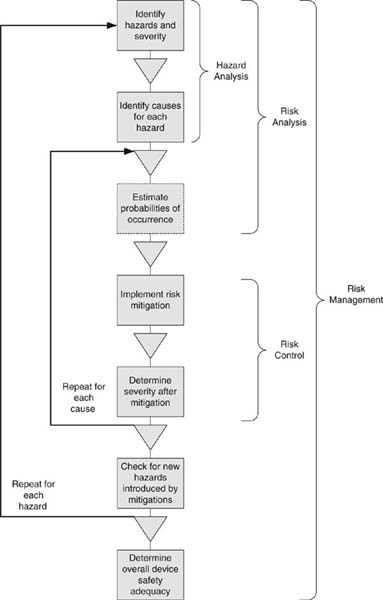
Figure 4.4: Risk management process.
What is needed in addition to the checklist is a process that analyzes the causes and consequences of a critical event. A critical event is something that could go wrong. The analysis should examine the possible causes of a critical event for insight into other types of critical events, and to prevent hazards as early in the design as possible. The process should also look forward to the possible hazards that may originate from the event, in order to provide a risk mitigation if warranted.
During the design output phase, when the response to the design input is being generated, the top-down approach should be supplemented with a bottom-up approach using more formal methods. The FDA will expect to see a formal method of risk analysis as part of the premarket submission. Not surprisingly, the extent of the risk analysis and the care with which it is conducted is a function of the risk class of the device.
The FDA does not specify the method for risk analysis, but international bodies require ISO 14971:2007, “Medical devices—Application of risk management to medical devices.” The FDA will accept ISO 14971, so following its procedures will simplify the approval process in foreign markets as well as satisfy the FDA.
Some of the formal methods include fault tree analysis (FTA) or failure mode and effects analysis (FMEA), or the more comprehensive failure modes and effects criticality analysis (FMECA). It is possible to estimate the quantitative probability of a risk, and these methods might include this risk analysis. When performing an FMEA at the level of individual components in an electronic assembly, the mean time between failures might be known and can be used for the estimate. As a rule, however, the probability of generalized risks is often unknowable beforehand, dependent as they are on the system design and problem domain. Extensive effort devoted to detailed quantification may be questionable, especially if it detracts from identifying as yet unknown risks or diminishes the design effort for mitigating the known risks.
Risk analysis is the process of identifying the risks and probabilities; once identified, risk control is the process of reducing the harm of a hazard as much as is practicable. Ultimately, the regulatory body with jurisdictional authority over the device evaluates the threshold that the device must meet. For example, failure of a pacemaker to generate the electric charge to pace the heart would be critical because it would necessitate surgical intervention to repair. Failure of the programming device that lets the physician set the heart rate would be of lesser concern, since presumably a backup would be available.
The risk analysis must consider the system as a whole. Few hazards are presented entirely by software; instead, it is the interaction of software and transducers or other hardware that could create hazardous conditions. The divide-and-conquer principle is applied; the subsystems are analyzed for hazards particular to their nature. However, software has its own types of hazards. Software can:
• Fail to do something it was supposed to do. It failed to perform an operation it should have, or failed to perform it in a timely manner, or failed to recognize or prevent a hazard that was the software’s responsibility.
• Do something that it was not supposed to do. It performed an unintended operation, or at the wrong time.
• Give the wrong answer. It shows data for the wrong patient or stale data, performs the wrong response to a hazard, or produces a false positive or false negative.
Risk control is the endeavor to reduce the risk to an acceptable level. Methods of risk control, in order of preference, follow:
• Design the risk out.
• Implement protective measures.
• Provide adequate information, such as warnings [3].
Eliminating the risk by design is the most preferred approach. For example, a left ventricular assist device that augments the patient’s natural heart by pumping additional blood could overpressure the ventricle and injure it. Overpressure could be eliminated by design by using a spring for the pumping action whose physical characteristics are such that it cannot create more pressure than a ventricle could bear.
To provide a software example: memory allocation routines are complex and may result in fragmented memory, so that a request for memory could fail. A method to mitigate by design is to allocate all memory at compile time and not use an allocation routine at all. (This is easier in embedded systems, where you are usually aware of all the resources that the system will require.) Hence you would prefer designs that avoid things like malloc() or recursion, or that otherwise have nondeterministic behavior.
Using protective measures to reduce the risk means designing in interlocks, alarms, and defensive code to protect against a risk or notify the user if it occurs so that she could intervene. For example, an x-ray system has a safety interlock so that software alone cannot command x-rays; instead, a hardware switch must also be depressed at the same time. As another example, software may poll a bit in an analog to digital converter to signal the completion of an operation. The code should include a loop counter and a timeout, so that the software can exit the loop if something goes wrong and the bit is never true.
The final line of defense is to provide warnings in the labeling that caution against improper or hazardous use. This may be the only option for some things: knives have sharp edges essential to their function, for instance. This really should be the last resort. Proper human factors analysis will show that risk reduction by design is a much more inherently safe approach.
Once the risk management is completed, you need to document the results, preferably in a tabular form. This should include descriptions of the hazards, the severity level, the software cause, the risk control means, the verification methods, and finally the severity level after the risk control method mitigates the risk. All software-related hazards should be reduced to the level where they present no risk of injury to the patient or user—in other words, reduced to the minor level of concern.
One wrinkle that can influence the result of risk analysis is institutional self-interest. Regulators can make two types of errors. They could be too accepting, and allow a dangerous device onto the market, whose problems are only revealed after it has done injury. Or, they could delay launch by insisting on extensive risk analysis and onerous risk management procedures, thereby denying patients the use of devices that could benefit them. If the regulator allows a device to “slip through the approval process that later proves harmful to some people some of the time, a hue and cry is sure to follow. Look no further than the recent public backlash against the FDA after several deaths were linked to Vioxx. . . .” [27]. The regulators are on the chopping block for not having foreseen an unforeseeable event. The second risk, not treating patients who could use the device rarely gets the regulators in trouble. Moreover, big manufacturers may acquiesce because it provides a barrier to entry to firms without the wherewithal to deal effectively with the regulatory bodies.
It is vital to think about hazards and mitigations early in the development process. Risk control measures are a major source of requirements; you want to avoid project and schedule surprises because hazards were discovered late. It is also more difficult to take a systemic view late in the project. Pasting the mitigations on at the end runs the risk of unintended consequences, and hence unsafe systems.
Example 4.3 Hazard Analysis Example
Hazard analysis is crucial but can also be difficult to grasp, so I will provide a fault tree analysis example based on a closed-loop insulin pump. While hazards are specific to devices, many times medical devices share a subset of the same types of software hazards, and many of the risk management techniques are the same.
Usually, a hazard analysis will be recorded in a table. Each row is a specific software failure that could lead to a system hazard. Multiple software failures could lead to a single system hazard, so the system hazard occurs many times. The columns capture the analysis that went into assessing the hazard, determining mitigations, and tracing through requirements and test plans to establish that the mitigations were met. The columns follow:
• Software hazard ID—It is useful to uniquely identify each software hazard.
• System hazard—The actual hazard that the software failure will lead to.
• Software failure—The specific failure of software that causes the system hazard.
• System effect of software failure—The effects of the software failure at the system level.
• System-level risk control—Risk controls at the system level, such as interlocks.
• Software-level risk control—Specific risk controls implemented in the software, such as watchdogs or self-tests.
• Severity—Level of severity of the hazard.
• Probability (optional)—Chance of the hazard occurring after mitigations. This is assumed to be 1 for software.
• Residual risk acceptability—The acceptability of the risk after mitigation.
• System safety requirements—Requirements imposed by the risk mitigation at the system level.
• Software safety requirements—Software requirements imposed by the risk mitigation.
• System requirements verification—Trace to specific tests that show that the system safety requirements have been met.
• Software requirements verification—Trace to software system tests that show that the safety requirements have been met.
Let’s examine the hazards presented by the example insulin pump.
Insulin pumps are currently available for the treatment of diabetes. They are worn under clothing and have a catheter shunt that goes under the skin. The patient uses a glucosometer to measure her blood sugar, and combined with what she has eaten and expects to eat, can calculate how many units of insulin to deliver from the pump. The next logical development would be to close the loop with a detector that assesses the need for insulin and automatically provides an insulin dose.
Two immediately obvious hazards are delivering too much insulin or delivering too little. If our device also had a readout that displayed the blood glucose determination, we have a third—an incorrect or stale readout that causes a patient or clinician to deliver inappropriate therapy. In a software-controlled device, these system hazards can all be caused by software failure, as well as other types of failures, such as the shunt coming out or the display failing.
(The third hazard—displaying wrong data causing wrong therapy—is common in medical device software, and in many cases is the most serious hazard they present. There are often alarms associated with the data, which presents the possibility of failing to alarm or alarming when it should not. Failing to alarm is not in and of itself a hazard, but is instead failure of a risk control in place to prevent a hazard. As such, it will not have system-level risk controls or system safety requirements, but it should be analyzed in the software hazard analysis because it leads to software requirements.)
Severity is an assessment of the extent of the injury if the hazard were to occur. These will differ by device. For a blood pump, for example, the most severe outcome might be output less the 2.0 liters per minute with no opportunity to intervene. For an x-ray machine, it might be excessive dose resulting in tissue necrosis and long-term tissue damage.
Severities are usually classified in levels and used as a shorthand. For diabetics, getting too much insulin is worse than getting too little. The patient can usually tell when she has too little and will have a backup insulin injection to manage the failure of the device. Too much insulin, on the other hand, can cause unconsciousness and the need for hospitalization. For the insulin pump, the following severities are possible (these are for illustration only and are not exhaustive):
S4—Excessive pump output without alarm
S3—Excessive pump output with alarm
S2—Insufficient pump output without alarm
S1—Insufficient pump output with alarm
Left Half of Software Hazard Analysis Table
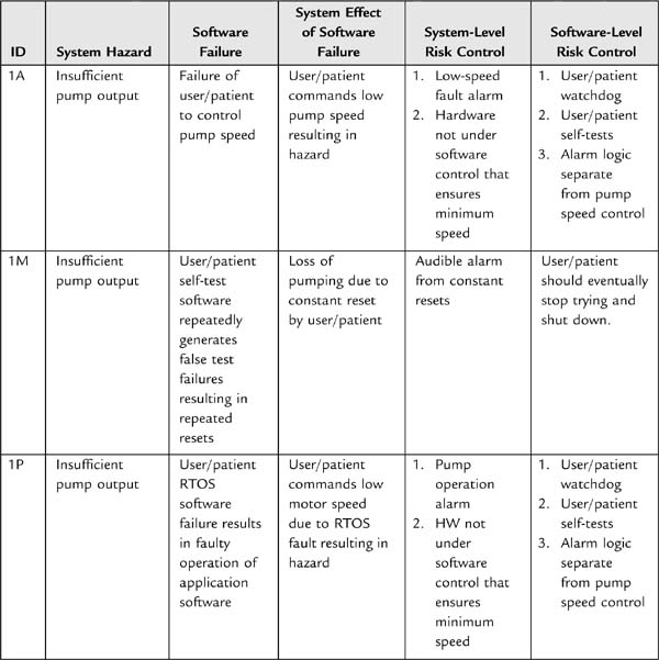
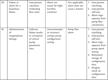
Right Half of Software Hazard Analysis Table
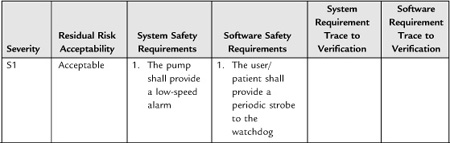
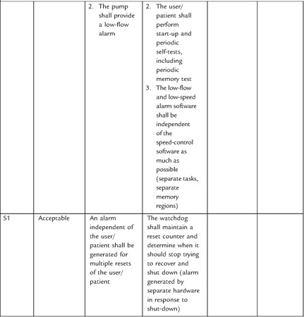
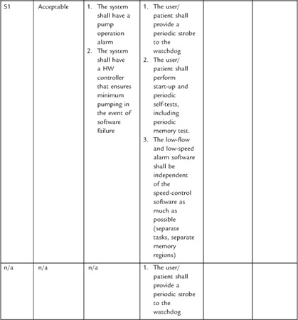
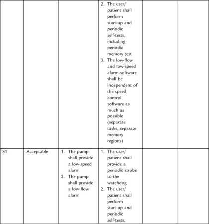

The fault tree analysis (FTA) carries on in this same vein, looking at a hazard and identifying the failures that could cause it to occur. This may result in some repetition, especially of the mitigations, but each subcomponent should be analyzed so as to ensure completeness. Excessive pump output could have the same software failure causes, but would have a different severity rating. A real software hazard analysis would have far more than five items, depending on the complexity of the device.
I have filled in the requirements columns for readability. You would want to use a trace to the unique requirement IDs to avoid stating requirements in more than one place. It is useful to flag safety requirements somehow so that the team understands their origin and importance—they should not be changed lightly! Also, fill in the traces to the test plans showing that the requirements were met.
FTA is a top–down approach. You may also wish to do a bottom–up approach—something more like a failure modes and effects analysis (FMEA). In this case, you would be looking inside the code for the types of ways that software can fail, such as overrunning a queue, and assessing what hazard could occur as a result.
5. Software Verification and Validation in the
Context of Design Control
We have reviewed the general requirements for design control at the project level. We have touched upon some possible software life cycle models. How does software fit into the design control process? In particular, what does software verification and validation look like?
Sometimes it is useful when talking about the role of V&V in the software life cycle to refer to the software V (Fig. 4.5). In this diagram, software development proceeds down the left leg of the V, and corresponding verification activities proceed up the right leg. So, requirements analysis precedes architectural design, which then leads to detailed design. Once the detailed design is complete, the implementation and coding phase begins. Then, proceeding up the V, the correct operation of the units is confirmed with unit testing. Units are brought together into integration tests, which verify the design. Finally, the system software test confirms that all the requirements are met.
To quote the guidance document, “Software verification provides objective evidence that the design outputs of a particular phase of the software development life cycle meet all of the specified requirements for that phase” [1]. In other words, verification is showing that design output meets design input. Testing—by which we mean a demonstration of operation or dynamic functional tests—is of course a vital component of verification. But verification is broader than functional testing, as it also includes inspections and analyses. This is significant because not all requirements are functional requirements that can be demonstrated by execution. These requirements are no less important, and should not be left out because they are not testable by the conventions of what has been thought of as “testing.” Thus “[a]ny approach which establishes conformance with a design input requirement is an acceptable means of verifying the design with respect to that requirement” [16].
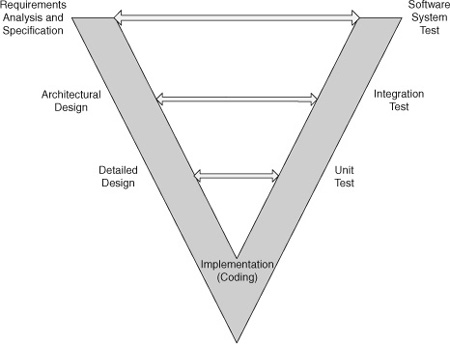
Figure 4.5: The software V.
Software validation, on the other hand is “confirmation . . . that software specifications conform to user needs and intended uses, and that the particular requirements implemented through software can be consistently fulfilled” [1]. This is a full life cycle practice and depends on the verification steps taken throughout the development of the software, rather than one activity done at the end. It includes “evidence that all software requirements have been implemented correctly. . .” [1].
In terms of the software V, verification is what happens in analysis between neighbors on the V. For instance, the architectural design should trace from and implement the software requirements. Verification is also the corresponding testing across the V. Validation, on the other hand, is the whole V—the sum of all the verification activities, plus measures to suggest that the trend of defects toward zero is sufficient to lead to a level of confidence that the software is validated.
There is some confusion possible between software validation and other kinds of validation, and in particular, design validation. It is unfortunate that the FDA uses the same word. In particular, the final test establishing that all software functional requirements are met is sometimes called the “software validation.” This is a legitimate interpretation of the guidance, which says, “A primary goal of software validation is to then demonstrate that all completed software products comply with all documented software and system requirements” [1]. However, I prefer to follow the ANSI 62304 standard in this instance, and call the testing which establishes that software requirements are met “system software testing.” This avoids confusion with design validation. (At a conference dedicated to software for medical systems, I asked in an informal poll of the audience what people called the testing in which you demonstrate that the software requirements are met. Half call it verification; the other half validation. I don’t think it matters much to the FDA what you call it, provided that your standard operating procedures or other planning documents clearly select a definition and stick to it. But the matter is avoided by calling it the system software testing.)
Software validation is a component of system design validation, but design validation must involve the customer and clinical evaluation to some extent, which would make it difficult if not impossible to confirm the correctness of all software requirements. You could hardly open the box and attach an oscilloscope to establish that the RTOS clock was running at 1 kHz, for example. On the other hand, some companies have made the mistake of thinking that design validation ends at software validation. To sum up, design validation for systems with software consists of:
• Conformance of software to its requirements (verification).
• Trace of software requirements to system requirements (we didn’t just meet the requirements, we had the right set).
• Validation that the device meets customer needs and is fit for its intended use. This involves both hardware and software.
After release, at the top of the V, the software enters the maintenance phase. Maintenance should be addressed as part of your software development planning. Generally speaking, you would use the same techniques, with a greater emphasis on regression testing. Software development in maintenance needs to be conducted with the same rigor as the original construction, or with even more care since the engineers who did the original work are often not available in the maintenance phase.
The software design input phase is the left half of the V. This is where you develop the plans to accomplish the life cycle activities, write the SRS, create an architectural design and a detailed design, and begin implementation.
Software development, as structured by the design control process, begins with quality planning. This is by and large expressed in the SOPs you have created for software development at your firm. These should describe the tasks for each life cycle activity and the methods and procedures for accomplishing them. For example, you might plan for a subset of the software team to write the SRS, and then have it reviewed by the whole team. You will want to define the inputs and outputs for the activities and the criteria for evaluating that the outputs match the inputs. It is important to describe the resources, roles, and responsibilities for the life cycle tasks.
This planning should include a SCM plan and the software problem resolution process that will be used. It should also include a software quality assurance plan (SQAP) that defines the quality assurance activities (such as are described in the next section) that will be used. For instance, you could define the method of unit testing as using test harnesses where practicable, or some form of automated testing. This is a high-level test strategy plan.
You want also to create a software V&V plan (SVVP). This is a more tactical plan that describes the breakdown into test plans per subsystem or per major feature, and details the test resources needed and so on. This document will have to evolve as the software design evolves, and you gain more knowledge about the types and content of integration testing.
The planning at this stage should be high level. You won’t have enough information to break the software development into work packages—not before the architectural design, for instance. But the idea is to plan the life cycle activities in general terms, such as the architectural design phase, without knowing about the internal details, until the design has evolved enough to allow you to plan in more detail.
Once you have general plans and policies in place, you develop the software requirements. These should follow—and trace to—the system design requirements. A major component of this phase is the hazard analysis, the evaluation of the level of concern of the software systems, and whatever software requirements derive there for risk control.
The hazard analysis is a direct input to the design process in another sense. One of the outputs of the hazard analysis is the level of concern of the software. You need this to know the appropriate level of risk-control measures to apply to the software. Since you can’t test quality, software must be constructed according to a careful life-cycle process in order to be safe [25].
Because the higher levels of concern require more exhaustive testing and documentation, it is also useful to partition the safety-critical software into its own software system. This will allow you to focus your attention on the most critical parts, and minimize the amount of effort overall.
With the software requirements in hand, you can begin the architectural design. It is probably beneficial to begin this design before the requirements are finalized, since trying to design from them is one of the first verifications that the requirements are feasible and complete.
Neither the FDA guidance documents nor the ANSI 62304 provides complete direction as to the dividing line between what is a software requirement and what is design, merely granting that it is “an area of frequent confusion” [25]. This is hard to know without experience or some examples. ANSI notes that software requirements often include software functional specifications that define in detail how to meet the software requirements, even though different designs might meet the requirements. The FDA guidance more clearly assigns this to design [1].
The architectural design is where you decide the software subsystems and modules (classes), and design the major interfaces and data structures. Further design refinement is carried out in the detailed design, where you specify algorithms and methods. The level of detail that seems to be expected is at the pseudo-code level or similar expressive artifacts, especially for major-level-of-concern software.
The architecture and detailed design is generally verified by evaluation, that is to say, technical review. But once we start coding the next stage of software development, we can apply a broader range of functional tests.
Software testing takes two broad forms: white-box and black-box testing. White-box testing—also known as glass box, open box, clear box, or, to the FDA, structural testing—is, as the name implies, a method of looking inside the code structure for the testing. It assumes that the tester knows what the software is supposed to do. It is a good way to look for errors of commission, and is the way that we confirm software is not working incorrectly.
Black-box testing—also known as functional, behavioral, or closed-box testing—tests the expected outputs against the inputs, without assuming any knowledge of what’s in the box. It cannot confirm that all parts have been tested, or that the software is not appearing to give the right answer for the wrong reasons. On the other hand, it is testing against the specification, and hence can catch errors of omission, where the requirements have not been met.
An aspect of white-box testing that is important to the FDA, and is in fact a powerful testing technique, is coverage. The basic idea is that complete testing would examine the condition of the software in every possible state it could be in. Obviously, this is impossible for all but the most trivial programs, so there are types of coverage that can be separately achieved.
• Statement coverage, where you execute every line of code in the program.
• Branch and condition coverage, where you test every program logic condition possible, and hence execute all branches.
• Loop coverage, where you execute all loops with variable termination conditions zero, once, and multiple times.
• Data flow coverage, where you watch the value of data as it flows through the program execution.
• Path coverage, where you take all the possible paths through the software.
The completeness of the coverage, both in extent and type, is a function of the level of concern of the software. The goal is 100%, but clearly this is difficult to achieve, especially for path coverage. Furthermore, 100% coverage generally cannot be achieved in black-box or functional tests. For one thing, it is difficult to create conditions in a functional test to throw an exception or invoke defensive code. The error handling is there, after all, to protect against software gone awry—without injecting errors under a debugger you can’t see it happen, precisely because it is not supposed to happen. And you wouldn’t want to leave out error handling or defensive coding because you can’t write a functional test to make it happen! So coverage is meant to be performed as a white-box test, primarily at the unit level [1]. We will see later in the section unit testing methods that can accomplish 100% coverage.
While appropriate at the unit level, white-box testing quickly becomes cumbersome, especially in real-time systems where the hardware can’t wait for humans to step through every line of code. Black-box approaches, on the other hand, are useful at all levels of testing.
There are several approaches to take to functional testing with increasing level of effort:
• Normal use, where you show that the software works with usual inputs, including forcing the software to generate typical outputs. This is necessary but not sufficient for testing medical software.
• Robustness, where you show that the software responds correctly to incorrect inputs. This is where you think of input equivalence classes, boundary conditions, and other analysis to derive the incorrect inputs.
• Combinations of inputs, where you test the behavior of the software when presented with multiple inputs in different combinations. Like path coverage, complex software can have tens of millions of combinations. Statistical testing methods that generate test data for you are generally necessary for accomplishing this type of testing.
Demonstration is not the only type of test than can occur. Indeed, some vital requirements cannot be safely demonstrated in production code at all, but have to be tested with parameterization or other white-box tests. For example, a watchdog is the final defense against errant software. But you wouldn’t want to leave test code in that tests the watchdog, on the off chance that a software failure happens to engage the watchdog test, causing the watchdog to trip when it should not. Nor is it acceptable not to test the watchdog, since it is an important part of the hazard mitigation. You could put a jumper in the wire to the signal that services the watchdog, and remove it in testing to simulate that the software failed to service the watchdog and verify that the watchdog resets the software. But a jumper could fall off in the field, causing artificial resets that had nothing to do with software failure. It is better to remove the jumper to enable the watchdog.
The testing will be a function of how elaborate the watchdog design is. In its simplest form, you could create a test harness with an infinite loop that locks up the software and verifies that the watchdog does in fact reset the processor. If your design incorporates a real-time operating system, your watchdog may take the form of a thread monitor which verifies that threads run as often as they should, no more and no less (within limits). I have found that a design like this, implemented early in the design of the project, will be verified repeatedly during subsequent development as engineers make mistakes elsewhere in the system, locking up threads and causing the watchdog to bite. This is an instance of error handling that when implemented early helps to debug the system while validating itself.
White-box and black-box testing techniques, as well as technical reviews, are the methods used to verify correctness through the construction phase. In the next section, I will describe the specific types of testing at various levels up the right side of the software V that are expected for any medical product.
5.1. Software Verification Methods
5.1.1. Example Review Process
As I mentioned in Section 3.5, Design Review, the FDA assigns special meaning to design review that is not the same as the term is often used in software development. We think of “design review” as the review of a software design; it may drill down to the level of a code inspection or walkthrough. These less comprehensive review activities the FDA would usually refer to as design verification. Because design review is something conducted at major milestones or is a project phase review, it is often an extensive undertaking. Of course, the extent is a function of the complexity of the product under review, but for moderate complexity projects, it will probably involve most of the development team and take several days.
The software engineering body of knowledge is ahead of the curve in the review process. It has been applied to software systems since Michael Fagin’s seminal work in the late 1960s. The design reviews that the FDA describes shares similarities with the Fagin-style reviews, but are a bit less formal. Shifting gears slightly, I’m going to talk about the design-verification style of review.
Designs benefit from well-conducted inspections and reviews. This is especially true perhaps of software, where the creation is entirely abstract and so must be evaluated analytically.
It has been argued that formal inspections are one of the best methods of finding defects. These could take the form of full-on Fagin formal reviews [28, 29]. These are formal scheduled meetings with trained participants taking on specific roles. First, there is the moderator. Her role is to schedule the meeting, distribute the materials, and follow up on the issues raised to their closure. During the meeting, she will keep the meeting on track and moving forward. Training in facilitating meetings and fulfilling the role of moderator is considered essential. The recorder is tasked with writing down the issues and producing the minutes. One to several reviewers add their technical expertise. Finally, the reader reads each line of the document out loud for comment by the other participants.
The author may or may not attend; this is a subject of some controversy. To be sure, management should not attend. The reason is that having management present will interfere with the give and take necessary to achieve the highest-quality output. A manager’s presence could inhibit criticism if team members don’t want to make each other look bad. Or in dysfunctional organizations, the manager’s presence could cause unnecessary friction between the reviewers and authors if one side wants to make the other look bad.
Most of the literature data are based on Fagin-style reviews, and the claims for its value are outstanding. To some degree, one wonders if its utility is in part a function of the nature of the documents reviewed that formal inspections are usually applied to. That is, if you have a thickly populated hierarchy of software documents, it is easy to imagine a lot of mistakes. For example, if there is system requirements spec, the parent of a subsystem spec, the parent of a software spec, which then repeats the information in great detail in the software design description, and beyond this there is a detailed software design description, then the code expressed as models, followed by the actual implementation of the models in a programming language, and then test plans that work themselves all the way back up to the system level, there are many points for failure. This is one reason for flattening the documentation where possible. So what may be causing the utility of the Fagin review is precisely this duplication of data. If the same requirement language, more or less, has to be traced through five levels of documents, then it is easy to see how it could get out of whack. The Fagin review examines these traces, accomplishing software quality, but not necessarily in the best way. Rather than attempting to inspect quality in to the work product, it would be better if the process emitted the right result by design. Moreover, it is the job of the organization to create products that work, not create reams of documentation that may distract from the achievement of safe, effective systems.
So, you may not need formal inspections, but there are several rules of thumb for reviews.
• Reviews should not last longer than 2 hours. Nor should there be more than one review meeting per day. We are after the best-quality work we can get, and people’s attention flags after 2 hours. (Besides, that is generally as long as an author can keep his mouth shut.) If the review has not been completed in 2 hours, reschedule. Sometimes with a substantial piece of work, such as a requirements specification, it is worthwhile to schedule routine meetings until the work is done. You might schedule a 2-hour meeting every day at 10:00 for the next 2 weeks.
• Reviews should focus on finding defects, not solutions. They should not be occasions for designing, brainstorming, blaming, pontificating, or other distractions. It is the designer’s job to come up with solutions. If your organization has trouble staying on track, it may be helpful to use a moderator. Decide how long discussion can go on before an item becomes an issue. To make good progress, discussion should normally not be longer than a minute or two. Use an egg timer if you have to. If the item cannot be resolved in 2 minutes of discussion, it is an issue. Write it down and move on.
• If your team cannot resist designing, you may benefit from a concept invented by NASA called the third hour. Reviews invite bright people with lots of ideas and opinions, so it is not surprising that they want to contribute. Plan an hour after the regularly scheduled meeting to consider solutions to the issues raised.
The formalism of a Fagin review may seem like overkill—and often is, when you are participating in one. It is perhaps best reserved for the most safety-critical components of the system. But there is one virtue in trying a few Fagin reviews. If a review process is a new concept in your organization, or you find that it is not very effective, using a formal process with a trained moderator can help the team learn what is expected out of a review and how reviews can be made more effective. Once a reviewing culture has been inculcated, then it is possible to relax the formality somewhat.
For instance, it would not be necessary to have an assigned reader drone through the document. Instead, the reviewers could project a document on a screen, read it for themselves, and suggest improvements that can be made in real time. (Don’t be too hasty though. Some changes may have ramifications to downstream documents or other parts of the system and thus need more careful consideration. These sorts of issues should still be captured in the minutes or issue log, and allowed to marinate for further solution, not in the heat of the moment.)
In smaller companies or projects, there may not be enough people to fulfill all the roles prescribed in a formal process. For reviews to be conducted at all, a less formal structure will be needed.
Review styles less formal than Fagin, but still face-to-face, are usually referred to as walkthroughs. This is a process wherein the authors guide the reviewers through the work product, and the review team, including the author, attempt to discover and resolve defects.
Because much of communication is non-verbal, a face-to-face meeting is usually the best method for controversial material, such as requirements analysis in the early phases of a project, and reviews of high-level designs. Depending on the sophistication of your team both at reviewing and understanding each other’s work, you could use a pass-around review instead of a meeting [16]. Routine code reviews could be conducted as a pass-around, for example, so that the reviewers can review at a convenient time and their own pace.
To conduct a pass-around review, the author checks the work products into the VCS (they are not distributed as hard copy). Next, the author or SQA schedules a meeting in the calendar software for the completion date for the review. This is a virtual meeting, not an actual meeting, just to remind people about the deadline. The reviewers respond with an e-mail with their issues. The author responds to each issue in turn with an explanation, or a fix, writing the response in the return e-mail. The response e-mail is attached to a review cover sheet, signed, and archived.
Such a review method works well with small teams. If there are a dozen people providing input, the collating effort required of the author can be excessive. In this case, a walkthrough meeting is more productive, since the same issue only has to be brought up once.
If you wanted more formality than the e-mail record, you could enter defects discovered in review into the defect tracking system. This is not needed in my organization; the author is trusted to fix the issues in response to the review, and then check in the reviewed work product. Only defects that were perhaps not in the scope of the work product under review, or that were not something the author could address by herself, such as changes to requirements, would be entered into the defect tracking system so as to reduce the process overhead of managing the response to review. What you don’t want to see happen is to have so much overhead or trouble caused by reviews that they cease to be effective, that is, people avoid pointing out errors because it is too disruptive to the team or too much trouble to fix it. This is a quality malaise that works against the goal of making the best products possible in a timely way.
How antagonistic reviews are is going to be a function of the culture at your company and the personalities of the people making up the team. There should be disagreement—otherwise, one would question the value of the review. But this can be reduced and time saved by holding informal review meetings long before the more formal methods, both so that the reviewers understand the work product when they get it, and so that it is not a shock when the first formal meeting is held. Also, plan time for issues that arise [16].
The value of informality is recognized by the FDA. “[T]he manufacturer should expect, plan for, and encourage appropriate ad hoc meetings as well as the major design review meetings” [7]. Decisions from these ad hoc meeting don’t necessarily require formal documentation, unless an important issue was resolved [16]. You can write some minutes for these meetings, summarizing the subject under review and the decisions. That way, you capture that cultural knowledge and get credit. These belong in the DHF. Routine activities that are part of your day-to-day job do not need to be documented [7].
At the same time, too much formality can reduce the delivered quality of a system. “Persons who are making presentations should prepare and distribute information to help clarify review issues and help expedite the review. However, the intent of the quality system is not that presentations be so formal and elaborate that designers are spending excessive time on presentations rather than on designing a safe and effective device” [20].
5.1.2. Unit Testing
The standard and guidance documents do not go into much detail about what constitutes a unit test, or even what qualifies as a unit, for that matter. For minor and moderate level-of-concern software, unit tests will not need to be supplied with the premarket submission. You are still expected to perform unit testing according to the methods you have outlined for the project in the SVVP. This gives you the freedom to define the unit test as whatever your process says it is.
A unit test could be as simple as a code review and whatever ad hoc testing the author thought suitable. This is satisfactory for software of minor level of concern. Another method that has become popular recently is automated testing. This idea evolved as one of the elements of extreme programming in which writing test functions confirm that the answer returned from a class method is the answer that the programmer expected [30]. (And may be the secret of its success. Some of the notions of extreme programming are, well, extreme, and not applicable to embedded or safety-critical systems, but the virtue of thorough unit testing is one of its great strengths.) Each routine has a test written for it, and these are collected in a test suite. Developers can run an automated test after each build to ensure that any recent changes have not broken any tests. This makes it a good way to do regression testing, especially because the cost is low. Test tools are evolving that even write the test for you, but an engineer still must be involved to evaluate their adequacy and what to do when they complain of a mistake. These can generate extensive reports that can be used to supply the requirement to provide test report summaries.
However, automated testing is almost solipsistic in the way it looks only inside the box. It does not test the fundamental assumptions of the requirements, and cannot check for errors of omission. If the engineer misinterpreted the requirements, it is likely he will misinterpret the tests. So it is by no means sufficient testing by itself. At the very least it requires a review to verify that the test methods meet the requirements. It may help to have someone other than the author write the tests, but nevertheless there is a danger of passing the test and being quite wrong, especially in terms of meeting the customer needs and being fit for the intended purpose. Integration testing and software system testing are still required.
Automated testing can also have only limited application. Usually embedded systems are interacting with physical input/output. Without a method of supplying to the test drivers the ability to observe and record the results of the operation, it is not very meaningful to write automated tests. Usually this feedback is provided by having a human observer. The tester presses a key and sees that an LED lights. It is possible to simulate the key press, but without a way to sense the corresponding action, the simulation is not very useful.
There are methods to address this but they involve the construction of special hardware. For example, you build a simulator that provides input to the software under test and evaluates the output. The simulator then runs a test script, providing the input and looking for a certain output. You might create your own drivers for a touchscreen, for example, that you can program to provide touches at random location and irregular time intervals. You could let this run for a while and at least verify that the GUI did not hang up.
One team built a simulator with photo detectors at physical locations corresponding to LEDs in the device under test, which is a clever way to observe the test output. You might also be able to use LabView, but keep in mind that LabView implementations would have to satisfy third-party software validation processes.
5.1.3. Unit Testing with Test Harnesses
Another process that has been successful in the embedded space is to write test harness for each unit. These test harnesses provide a framework in which to do whatever type of testing is called for. The test harness can be written to automate the tests, providing simulated input and verifying the correct output (especially useful for regression testing). The test harness can be used for performance testing of the module’s subroutines, for example, by strapping clocks around the call to measure how long they take to execute. It is nice to do this in a test harness so that the results are not skewed by other things that might be going on, like servicing interrupts or allocating some CPU cycles to the execution of another thread.
You can write stress tests into the test harness, testing boundaries, memory limits, resource pools, or executing as fast as possible by throwing messages at a routine far faster than the physical system would generate them. And a test harness is the ultimate white-box test, allowing all source lines to be stepped through with a debugger; all logic, including error handling, to be executed; and all outputs to be observed to verify that the code is not working incorrectly. Hence you can exhaustively test the permutations and achieve 100% statement, branch, and condition coverage, if not path coverage, at least for the unit under test.
The principle of this approach to unit testing is to only implement a handful of requirements at a time. Only these few requirements are met, but they are concretely met and completely verified. The implementation can be used in a working system to start integration testing or even to get a subset of functionality into a user’s hands to begin the validation of the requirements, that is, that task of showing that the requirements meet customer needs.
In this method, the unit is the fundamental organizing component of a project during the implementation phase. It is the basic work product and its completion is the measure of project progress. The definition of unit is “the minimal testable set of functionality.” (This also fits with the definition of a unit as described in ANSI 62304 §B.5.4.) A unit may map to a file or module, if the definition of a module is source code and an associated header file. But it does not have to and sometimes cannot. Multiple files may be required for interrupt service, for example. It would not be prudent to violate other rules of good software design and decoupling just to fit a program structure into some kind of unit bag. The goal is nevertheless to organize the code and its implementation based on its testability.
Every module gets a test harness, if possible. Test harnesses are archived work products in the VCS that are retained throughout the software-product life cycle. It can actually be included in the source code, activated with the use of conditional compilation. (In C this could take the form of #ifdef TEST_HARNESS. Then when building the test harness, define TEST_HARNESS to the preprocessor.) It could be a separate artifact with a different extension. (So a unit might consist of test.h, test.c, and test.th.) Either method ensures that the code that is integrated is identical to the code that is tested, both verifying the unit testing and making integration easier.
The following code listing is an example of a simple routine to calculate the median of a set of data and its associated test harness. The main routine of interest is TakeMedian(). It happens to need a sorted array in order to do its work, so the SelectionSort() method is also supplied. (This could alternatively be in its own library.)
Two test regimes are needed: for a data set with an even number of elements, where the two middle values are averaged, or an odd sized data set, where the middle element is selected as the median. In addition, two flavors of data are tested—one with widely dispersed data, and one with narrowly dispersed data—to reveal problems with duplicated values in the data set, or mixing negative and positive, for example.
The printfs show the expected result. This could as easily be an automated test, where the computer checks the result and reports pass or fail. Also, the test harness could be extended to test different data set sizes, especially the null data set, or one or two elements only. This is left as an exercise for the reader (Fig. 4.6).
Each unit is completed when it passes a code and test review. The code review establishes that the software implements the requirements that it was supposed to, and the test review is an opportunity to verify that the tests are comprehensive and correct. Since it is in the VCS, the test code is available whenever the unit requires retesting—in the event of refactoring or porting to new hardware, for example, or any other needed regression testing. It also provides an example of the way to use the routines implemented in the unit and the boundaries of their use, since boundary conditions should be captured in the test harness.
One issue is whether to maintain test harnesses and what to do about changes that occur after the unit test is completed. You only have to comply with your own policies, and you may want to make the degree of review and regression testing a function of the risk class of the module. In my own practice, I do not require test harnesses to be maintained in the general course of development. Since there is in my projects at least as much test software as application software, such a policy could easily double development time—and not for a particularly beneficial result. The test harness code is available in any case as a starting place if something changed sufficiently to need retesting, although it may have to be refactored to adapt to changes made in the main line code in the course of integration.
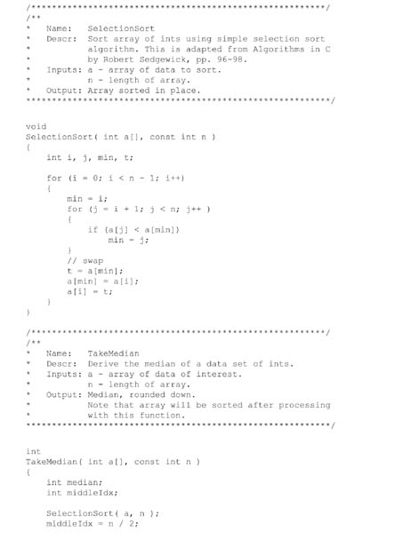


Figure 4.6: Unit test code example.
Note: Just because it is test code does not mean that the code quality can be any less than required for the level of concern of the software! [1]
You can allow minor changes to be tested in integration tests—it should not be necessary to retest an entire module because a data type changed from signed to unsigned. The same is true of reviews. If code reviews are going to have the most value, they need to be conducted early in the life of the unit, when design errors are still fixable. What is necessary is to have a policy for evaluating whether changes have been sufficient to warrant a follow-on review.
It is key that the testable code be minimal. The whole idea is to limit how much influence external code can have on the unit under test. Write the test harness to stand alone. Use stubs in the test harness code to reduce the connections to called functions and/or to simulate their functionality. If you follow the principle of minimalism, and make an effort to reduce the linkages, the smallest amount of data that the unit needs will become obvious. You can then make the data local in scope and provided by the test harness. At the least you will understand what external data the module is coupled to. If the data are complex, you may find it necessary to use test scripts or files (also archived in your VCS) to provide simulated data.
As for what guides the organization into units, it will depend on your requirements, architectural design, implementation language, inclination, and experience. If you are developing a multitasking system, it is often smart to implement a thread per unit. The test harness can simulate input messages to the thread, and stub out the output thread. The input messages can be controlled with a script and hence different circumstances can be simulated that might occur rarely in actual use. The output can be verified against the input—you can use the computer to automate this testing if you choose to.
A unit usually implements only a small subset of requirements. Depending on the SRS level of detail, this might be on the order of 2 to 8. The cohesion of a limited set means that the project leader can assign the development engineer a unit of functionality to implement. It simplifies the problem to the level of providing one cohesive, distinct service at a time. This is also usually in a small enough chunk to enable project tracking and oversight.
Another virtue of being focused on units is that you can use a phased approach to implementation. For example, say that the unit of functionality you have decided to work on is the implementation of the analog-to-digital (ADC) conversion routines. The first phase may see the ADC implementation using a polled mode and minimal configuration of the hardware. This lets you verify that what may be a new hardware design is in fact working. The next phase is to initialize the device for interrupt operation. Since interrupts can be tricky to get running, there is an advantage in already knowing what to expect from the device. There is less to debug all at once.
Once you have established that the ADC interrupts are working and giving you expected data, you can add channel calibration. This is also the time when you might consider characterizing the way that the hardware and software work together. You can measure the linearity, signal to noise, response to step input, and other parameters important to validating the functionality of the system. You can focus on the components under study, reducing the interaction with the rest of the system that might confound the results and interfere with debugging.
There are some things to watch out for with a phased approach. You don’t want to get stuck in doing things differently than the final application so that you are misled into thinking you know something you don’t. You also don’t want to be doing the same thing, just in a different way. These worries should diminish with experience.
The requirements that a unit implements should be well bounded. So should the amount of effort. It should be possible to implement a unit on the order of a few days to a week. It might be only a few hours if that constitutes as sensible unit. This is a short time frame, so there is only so much code a person could write. This means that units tend to be a few hundred lines in length, including the test harness. Shorter modules are far more manageable than 5000 to 10,000-line modules. It is also much easier to get someone to review a short module. It is going to be difficult to do an effective review of 5000 lines of code, and usually too late to do anything about it if there are issues. It is much cheaper and easier to throw away 50 or even 500 lines than 5000 lines. Human nature (and project exigencies) makes it hard to discard the latter, regardless of how unsuitable it may be.
The small size and the short amount of time spent on development also encourage good cohesion, and especially loose coupling. Coupling is obvious in the list of files that the test harness links. (This could actually be used as a metric.) Sometimes the list is quite large and it is inconvenient to specify each file that has to be linked to create the test harness. For once, an inconvenience is a virtue: it encourages the engineer to loosen the coupling. It is an inducement to decouple through refactoring interfaces or hiding data, or even developing a well-structured library. Faced with the alternative of linking everything every time, software engineers think a bit more about global data, linkages, and coupling.
As more and more functionality is implemented, the units are bolted together into more comprehensive integration tests. These have test drivers of their own, and ought to have formal test plans. The purpose of the integration test is to implement and verify a subsystem. The purpose of the test plan is twofold: it is a reviewed document that establishes that the verification is adequate and the testing is complete, and it is a necessary element in the premarket submission for higher level-of-concern software.
To extend the ADC example from above, the final package might have five units. The first unit tests the initialization of the ADC hardware and the setup for interrupt service in the application. It outputs raw analog values from the ADC channels. The next unit tests the calibration of the analog data. It did not use raw data in its unit test; instead, test data were provided to it to demonstrate the properties of the calibration transfer function. For example, it was verified that the calibration could handle the complete range of data that could be presented to it, including error values. It was also verified that the calibration transfer function would transform the data correctly, with complete understanding of rounding errors and the effect of bit errors in the ADC on the final result.
Another unit is required to interface to the transducers connected to the ADC. General-purpose output is needed to control the transducers for wraparound tests, or it is necessary to control a multiplexer to read multiple channels.
A fourth unit accepts the output from the ADC and filters it. The unit test of this consists of providing known input to the filter and examining the output. This can be done analytically by writing a console application to read an input file, process with the filter, and then write it out again. Or you could use a desktop application, such as an Excel spreadsheet—certainly Excel would be a good way to see the results of the filter. (Just remember to verify that the output of the third-party tool is correct—see Section 6.1, Software of Unknown Provenance.)
Finally a unit takes data from the filter and displays it. The embedded application does not need to display the data, but debugging and verifying the system greatly benefits from returning to an analog form of displaying the data so that human brains can easily process what has happened in the “black box.” The displayed trace can then be compared to the raw data seen in an oscilloscope trace and the processing verified and characterized for things like response to noise, ringing, response to a step function, and phase shift through the filter. This is an example of writing code that is necessary for developing the product but not for the final product. Sometimes in R&D you’ll write a lot of code that you are not going to keep—it is necessary to write the code to verify the system. This display driver application could be the integration test harness for the ADC subsystem. The test plan would consist of this characterization of the whole thing, from signal input to the output in the display unit.
Note that each of these units was separately demonstrated with test data before integration into the whole. The engineer already had experience with the end result if something was haywire—if the ADC hardware was faulty, for example. You can trace the source of the problem, because you have already determined what outputs will occur from what inputs. Instead of seeing some value that did not seem to change, the experience allows the engineer to know that he is seeing the ADC rail, or is excessively noisy, or is otherwise not getting the input expected. The system is testable. You can apply a stimulus before or after the transducer and check its output. If something unexpected is going on, the test harness is available for a suspect unit. You can rebuild the test harness, poke it with bad data, and explore what is going on.
As more and more of the system is implemented, the same activity occurs over and over again. More and more subsystems are built, and these are integrated into larger and larger components with corresponding integration test applications. The integration tests become the deliverables for integration milestones wherein you demonstrate that parts of the system or particular features are working. (I am assuming some iterative development life cycle here.) Eventually, the delivered system is the integration of all the subsystems. They have been fully tested all along the way, down to the unit level. You are able to provide the unit, integration, and system test documentation for the premarket submission, if needed. If problems show up in integration or if hardware breaks, you have the test harness available to investigate suspect code. If there are changes to requirements, or if defects arise, you have the test harnesses to explore the defects or retest the changed requirements. The system is decoupled so that you can make reasonable arguments about how much regression testing to apply, and you have the integration test drivers and test plans available so that you are not starting from scratch when regression testing is needed.
5.1.4. Static Tests
Static tests are analyses performed without executing the software. Probably the most used static test is a code review. This could take the form of a highly formal inspection or a more informal code review; the rigor you use should be related to the level of concern of the software. Per ANSI 62304, code review is not optional on moderate or major level-of-concern software, since it is the basis of the acceptance criteria applied to a unit before it is acceptable in integration [25].
Code review should take place against a coding standard in order to realize aimed-for code characteristics. The coding standard is one of your software process control documents. It should spell out the desirable code characteristics, such as understandability, flexibility, and maintainability. It should describe layout conventions, such as spaces or tabs and the tab indent, as well as the bracing style, so that code developed by several team members will be consistent. Naming conventions are also important, so that the same thing doesn’t get several names, which can lead to confusion. You should capture policies on complexity and the length of subroutines, and forbid language practices that are error-prone.
There is some difference of opinion on when to perform code reviews. Should they be carried out before doing any testing, or do you review the tested result? There is even the idea that code reviews are better than nothing, but not by much.
The answer, as in so many things, is that it depends. Both the culture of the organization and maturity of the team with the coding standard will be influential. If you have a new employee, or someone who is a bit of a cowboy, you might want an experienced engineer to review the code before a lot of time is invested in testing it. If there are big changes, refactoring to shorter routines, for example, you would have to conduct the testing over again.
On the other hand, in my company we tend to review after the code has been written and tested, so that the code review functions as a test review also. This works because we have technical design reviews before the implementation. Without the design reviews, a code review is sometimes the first time anybody sees a design—and by then, so much has been invested in time, testing, and emotional energy—that the team may tend to commit to bad designs. In any case, the policies that describe your review process should spell this out; it is then a matter of following your own guidelines.
For what it’s worth, the guidance document suggests that code review be done before “integration and test” [1]. This is ambiguous with respect to whether it is done before unit testing. What is important is that the results of the review methods and results be captured in the DHF. Review checklists are a handy way to do this. See many of the good texts on code construction for sample checklists.
As for keeping track of whether the code review took place, there are several methods. The most rigorous would be to restrict the ability of the author to submit changes to the VCS. Someone else would have to do it for him, only after checking that the code review had been done, or doing the code review as part of the check in. Normally this would only be needed for released software. A similar method would be one that restricts who may promote a code change to a branch. Then software quality assurance would verify that the code had been reviewed before integrating changes from development branches and rebuilding the software.
Some VCSs have a promotion model attribute that is applied to archives. Then code modules would be promoted to reviewed status; if the file is subsequently changed it drops out of reviewed status. It is then necessary to run a report before release to verify that all of the software is in the proper promotion group. You could do the same thing with a label. You apply a label such as “Reviewed” to any code at the revision that the team reviewed. If the code changes and needs another review, you move the label. As in the case for promotion groups, some kind of audit is required to verify that the released code has all been reviewed.
A last method would be to wait until the software is ready for release, and then conduct all the code reviews at once on the final code. This might work for small projects. However, it is generally unwise. Projects are usually under some time pressure close to release. About the last thing you want is a lot of pressure to conduct code reviews. It is unlikely that the reviews will serve the purpose of finding defects—no one will want to change anything and start the process over, no matter how flawed the software might be. To get the maximum benefit out of reviewing code, the earlier in the process the better.
Some tools have emerged to verify compliance to a coding standard. It is quite common for modern C compilers to have an option to verify compliance to the Motor Industry Software Reliability Association (MISRA) C language guidance. MISRA C is a subset of C that disallows use of its more dangerous features.
A program called lint has been the classic static testing tool for C and C++ code. It performs a very detailed syntactic analysis and can add strong data typing to the rather fast and loose C-type of environment. Unfortunately, it can be about as much trouble to get running as any bugs it finds—it is not necessarily superior to code review. For deeply embedded systems in which typing is problematic, it can be quite inconvenient.
Recently, other tools have emerged that purport to evaluate the software for semantic errors; run-time errors, such as divide by zero; out-of-bounds array access; and memory leaks, among other things. The most important automated static test is to put the compiler on a high error level and make sure that you have a clean compile. Modern compilers usually have quite good error checking that is more forgiving than lint. Any errors in the build would need to be documented in the software build and release documentation. For example, when I build I get a bogus warning about an overlapped memory segment, a result of having located constants in memory so that I can check their validity during runtime. My build documentation explains why this is bogus and safe to ignore.
5.1.5. Integration Tests
Integration testing is overloaded with two meanings. It refers both to integrating software with hardware and the integration of multiple modules into software subsystems.
To accomplish integration testing in the first sense of the word, you demonstrate the hardware and software working together to produce correct output. This is often done by providing a known input to the hardware and observing the result when it is processed by the software. For instance, you could use a function generator to simulate a square wave at the signal input to the hardware at a certain frequency and level. After signal conditioning in the hardware and whatever conversion, calculation, or other processing occurs in the software, the signal should be comparable or representative of what the original input looked like.
Software integration testing in the more usual sense is the testing of the aggregation of software units into larger subsystems. I have already described how it is a natural incremental progression from a unit focused approach to development. Of course, the project does not have to develop that way. In any case, integration testing should concentrate on data and control transfer across both internal and external interfaces.
In integration testing, you need to verify that the software performs as intended and that the testing itself is correct. You must document the results, especially for moderate and major level-of-concern software. This should include expected results, actual results, the pass/fail criteria, and any discrepancies. The tester must be identified, and you should retain the test plan and records of which version, which hardware, and so on, so that the test could be repeated. If the testing is going to be part of a regulatory submission, you need to identify any test equipment and its calibration, per the QSR.
It is acceptable to combine integration testing and system software testing, although you would normally only do this for simpler, less risky projects.
5.1.6. Regression Testing
Regression testing is testing engaged after a change is made to the software. Its purpose is to demonstrate that the software still meets its requirements and that no new defects have been introduced. This is a subject of great interest to the FDA staff because they have observed that, of the product recalls attributable to software defects, 79% of those defects were introduced as a result of changes made to the software after deployment [1].
Where the level of concern of a component is high, regression testing is particularly important to verify that safety requirements are still being met. The requirements assigned to software for detection or mitigation of hazards must still be met after a change.
The minimum requirement for regression testing is a test protocol that demonstrates the major functionality of the system and the safety features, where practicable. This should be conducted after each build. Some organizations use the regression protocol as a “smoke test” to assess the quality of daily builds as a means to discover problems as soon as they are integrated.
The regression testing needed as software naturally evolves is part of the utility of developing software in units with test harnesses. Loosely coupled systems are easier to change, and easier to test. It is easier to create a justification for limiting the testing to the modules that changed, rather than repeating every test for the project. This is also a function of the nature of the change and the criticality of the software.
5.1.7. Auditable Build
By definition, the DMR is supposed to provide the information to trace everything that went into the manufacture of a device to its point of origin. This extends to source code. In the event of a customer complaint or recall of your device, you may be required to re-create from source the software that went into the device. Being able to do so might save you from rewriting the whole thing from scratch if there is a minor error to fix.
To support this, one consideration to have in mind when releasing software is to audit the build so that you can be sure you have all the elements needed to re-create all executables and other deliverables from their sources (usually in the VCS). You want to be able to produce the records of any released configuration item [25].
The ultimate method would be to install everything—operating system, code generation tools, VCS, and source code—on a new or clean computer. As a rule, it is probably sufficient to build in a clean directory. This assumes that you were careful about documenting the special setup steps that the tools might have needed. For example, it is easy to forget years after you installed a compiler that the command line needs environment variables set to specific values. If you were to do a full install, you would be assured that you understood all of the setup steps needed. A document that describes the setup steps to install the tools needed for software development is a useful document to have for this reason; it is also handy when you have a new employee or get a new computer.
Depending on the criticality of your device, in addition to the auditable build, you may want to consider locking away in a closet the build computer, or at least its hard disk. Since most of us are performing development in commercial operating systems and computers, even with the full source code and tool chain, it is possible to have trouble running tools on newer operating systems. The pace of change is so fast in the commercial systems that sustaining identical functionality for years is difficult if not impossible.
5.2. Software System Testing
The pinnacle of software testing is the software system test. This is where you show that all of the software requirements have been met [25]. You do this by providing input (“Apply calibrated reference heat source to the probe end”), expected output (“View the reading on the display”), and the pass/fail criteria. (Verify that the display reads between 39.8 and 40.2 degrees C—for this simple example of a digital thermometer.)
This is also known in some companies as the software validation. Because software validation is a larger subject, namely, the construction of software using a defined, rigorous process, I prefer the term software system test, as defined by ANSI 62304.
Software system testing usually consists of a set of test protocols executed when the software is complete. These can be organized in different ways—they could be organized by the software system specification, in other words, map to the SRS, or they could be organized by features that cross SRS boundaries. You are free to organize them as you like; test management software would probably be helpful. You do need to make sure that, whatever organization you use, you can show that all requirements have a corresponding test somewhere.
This brings us to our first difficulty. There are other kinds of requirements besides functional ones. For example, assume that we want to specify the initial settings of registers in the microcontroller, so that unused general purpose I/O pins are set to inputs to use the lowest power. They are unused and hence by definition have no function. Or we might want to specify the development language or the hardware that the software is designed to run on. How do we test these requirements?
Not all requirements are functional requirements. We don’t want to leave them out of our requirements specification (a solution I have seen more than once) because the system design would be wrong if we did not include them. But they cannot be verified with a black-box test.
These types of requirements will have to be verified by other means, usually an inspection. When the traceability analysis verifies that a requirement has been met, it can point to a code review or unit test that provides the evidence. And they can be done early. Not all requirements have to wait for the final software system test to be verified. (You would have to be sure however, through a label or promotion model in the VCS, that the software had not changed since its inspection.)
I have already mentioned that there is no one defined way to organize your software system test protocol. However, there is an interesting formalism that has been the case at all the medical software firms I am familiar with. I am not exactly sure why this formalism evolved—it is not specified in any of the literature. I believe that it originated in the practice of having tests describe expected results before the testing including pass/fail criteria, plus FDA requirements for approval signatures. It makes more sense for statistical tests applied to hardware components, such as in testing the burst pressure of a balloon catheter. It has been adapted to software testing, where the outcome is much more deterministic, so this style of testing doesn’t make quite as much sense. Nevertheless, this is what it looks like.
The software system testing consists of three phases. In the first phase, you write the test protocol, have it reviewed, and get it approved. Of course, since the best review is to actually execute it, you usually have a good idea of what the test results are going to be. Once approved, it is executed and the results recorded. This must be by someone who is not the author and is not responsible for delivery of the product, to avoid blind spots and conflicts of interest. Then the test results are summarized and a final report written. (I have known some firms to type up the test results to avoid questions from the premarket submission reviewers about reading the handwriting of the testers.)
The test results must include the following:
• The date of the test.
• Identification and signature of tester.
• Identification of the software configuration under test.
• Identification of the test articles—the serial number and configuration of the medical device used for the tests, for example.
• Identification of test tools and equipment used. This equipment must be calibrated.
The objective is to supply enough information so that the test could be repeated some time in the future to get the same results.
In spite of our best efforts, it may not happen that the system passes all the tests. Sometimes the test plan itself was misinterpreted or in error. You don’t have to keep iterating the test plan until it passes. What you do instead is to write an exception or deviation to the test. For each test that failed, you write an explanation for why it failed and provide a risk assessment. In the case of a test plan failure, this may be a simple matter of redefining the test procedure and rerunning the test.
If you plan to release the software with the defect in it, the risk assessment must provide a rationale for how the software is safe and effective in spite of the presence of the defect. You will have to provide a list of the anomalies in the software along with any premarket submission.
You can also use the SPR process to record the test plan failures, and manage the test plan failures with the normal procedures. One good way to deal with defects in the test plan is to explain in the exception report that the test was modified, rerun to show that the software itself is correct, and has had a defect entered for the test procedure that will be corrected at next revision of the test protocol. This method closes the loop on the defect.
Once you have completed the software system testing, there is a step left that is peculiar to medical software—certification of the software. Like the formalism in the test protocols, it is not exactly clear where the need for this originated. I believe it relates to requirements in the QSR for signatures affirming that the quality policy has been followed. (It may be a method to criminalize noncompliance to the QSR. Were you to sign such a document and the FDA could prove that you had not followed the process, you might be susceptible to a charge of perjury.)
The certification is a written statement that the software complies with its specified requirements and is acceptable for operational use. In it, you also certify that the software development process of your organization was followed. You should also include a checklist of the control documents created during the software development. These deliverables are related to the level of concern of the software and will have been spelled out in the software development plan. The checklist is to ensure that all are complete in the release package.
The certification itself should read something like the following. The actual titles and signatures depend on your company’s quality policy and organization.
My signature affirms that the software was developed according to procedures in SOP-XYZ and test results demonstrate that the product meets its specification.
I specifically certify that:
I have verified that all required deliverables are on file.
The documents in the DHF reflect that fact that the software followed the software development life cycle.
All tests in the software system test protocol were performed and meet the specifications for safe and effective software.
Approved by: _________________________ Software Engineering Manager, date
Certified by: _________________________ QA Manager, date
With the certification in hand, the software deliverables archived in the DHF and the software release itself in the DMR, we are ready for the system design validation that will demonstrate that the device itself is safe and effective.
FDA cautionary note: “Testing of all program functionality does not mean all of the program has been tested. Testing of all of a program’s code does not mean all necessary functionality is present in the program. Testing of all program functionality and all program code does not mean the program is 100% correct! Software testing that finds no errors should not be interpreted to mean that errors do not exist in the software product; it may mean the testing was superficial” [1].
We can only be diligent. But don’t assume because all the tests were passed that everything is perfect. We must take care that the tests test what we mean them to test. Getting the tests right is about as hard as constructing the software in the first place.