CHAPTER 5

Best Practices in Spacecraft Development

Chris Hersman and Kim Fowler

This chapter covers the practices and processes for developing unmanned robotic spacecraft beginning with a section on regulations and standards. This chapter does not address the design of man-rated spacecraft. These standards represent proven practices from government and industry. Following the regulations and standards are two sections covering examples of company processes and documentation that are typical of a successful spacecraft mission. In general these practices are implemented to meet the relevant requirements outlined in the regulations and standards, while enforcing consistency across projects for different customers. Examples of documentation of standard practices as well as project-level documentation are identified. Finally, this chapter wraps up with a case study of a successful NASA mission and the obstacles encountered during the project. The focus of this chapter will be on the aspects that contribute to reliable and successful missions.

1. Regulations and Standard Practices

Resources for many government regulations and standard practices that relate to the development and launching of space missions can be found online. Listed below are relevant documents with online sources cited. In some cases additional related information may be found on the referenced website. For each regulation or standard practice listed, a summary description is given, along with an explanation of how it relates to the development of a space mission.

Government standards and regulations tend to hold sway in developing spacecraft. Commercial standards are less developed but generally tend to follow the government standards.

1.1. Government Regulations

The U.S. government agency that issues most spacecraft-related regulations is the National Aeronautics and Space Administration (NASA). NASA regulations come in the form of NASA Procedural Requirements (NPR), NASA Policy Directives (NPD), and NASA Technical Standards.

1.1.1. Project Management

1. NPR 7120.5, NASA Space Flight Program and Project Management Requirements (http://nodis3.gsfc.nasa.gov/). The purpose of this document is to establish “the requirements by which NASA will formulate and implement space flight programs and projects.” Topics covered include program and project definitions, program and project life cycles, reviews, roles and responsibilities, lines of authority, project and program phases, and templates for program and project plans. (See Figs. 5.1 and 5.2 for a graphical depiction of the elements and timeline used in systems engineering to define requirements, roles and responsibilities, and project phases.)

2. NPR 8000.4, Agency Risk Management Procedural Requirements (http://nodis3.gsfc.nasa.gov/npg_img/N_PR_8000_004A_/
N_PR_8000_004A_.doc
). The purpose of this NASA Procedural Requirements (NPR) is to provide the minimum requirements for the planning and acquisition of NASA facility projects. Risk management includes two complementary processes: risk-informed decision making (RIDM) and continuous risk management (CRM). This NPR establishes requirements applicable to all levels of the Agency. It provides a framework that integrates the RIDM and CRM processes at all levels. This NPR also establishes the roles, responsibilities, and authority to execute the defined requirements.

image

Figure 5.1: Systems engineering functions, with interrelationship of major system engineering functions (while this figure derives from the military world, it has elements that fit developments for spacecraft and space instruments). Goddard Procedures and Guidelines, “Systems Engineering,” DIRECTIVE NO. GPG 7120.5, p. 6. Available at: http://spacecraft.ssl.umd.edu/design_lib/GPG7120.5.pdf

image

Figure 5.2: Systems engineering life cycle relationship with project life cycle, with major goal of each phase.

3. NPD 8610.24B, Launch Services Program (LSP) Pre-Launch Readiness Reviews (http://nodis3.gsfc.nasa.gov/). NASA is accountable for program mission success, which includes launch success. NASA assesses and certifies the readiness of the launch vehicle, payload support hardware and software, and preparation of the launch site infrastructure through a structured prelaunch review process. NASA conducts a Launch Services Program (LSP) prelaunch review; it entails the following:

• Launch vehicle readiness review (LVRR)—Certify readiness for integration of the spacecraft and launch vehicle; typically conducted before the mission readiness review (MRR).

• Flight readiness review (FRR)—Update the mission status, close out actions from both the LVRR and the MRR, and certify readiness to initiate the launch countdown. The FRR is held about 3 days before launch.

• Launch readiness review (LRR)—Update the mission status, close out actions from the previously held FRR, authorize approval to proceed into launch countdown, and sign the certification of flight readiness (COFR). The LRR is held 1 day before launch.

• Final commit-to-launch poll—Confirm readiness to launch approximately 5 minutes before launch. A “go” statement is required from all parties polled to enter into the terminal count. Mandatory launch constraints cannot be waived after start of the terminal launch countdown.

The mission spacecraft usually has a parallel set of prelaunch reviews for the spacecraft and ground system elements as well as status of the launch service. The Spacecraft MRR is typically held after the LVRR. The project may hold other reviews deemed appropriate and necessary to prepare for launch; examples include System Requirements Reviews, Critical Design Reviews, Design Certification Reviews, Preship Reviews, Ground Operations Reviews, Project Manager’s Reviews, and safety reviews.

4. NASA Cost Estimating Handbook 2002 (http://cost.jsc.nasa.gov/NCEH/index.htm). The NASA Cost Estimating Handbook (CEH) provides a balance between documenting processes and providing basic resources for cost estimators without setting a tone of strict guidance. It is a top-level overview of cost estimating as a discipline, not an in-depth examination of each and every aspect of cost estimating. It recognizes the nature of NASA systems and the NASA environment. This handbook claims that cost estimation is part science, part art and that it is a starting point for accurate, defensible, well-documented estimates that are consistently presented and can be easily understood.

1.1.2. Systems Engineering

1. NPR 7123.1, NASA Systems Engineering Processes and Requirements (http://nodis3.gsfc.nasa.gov/). This document is a NASA Procedural Requirement (NPR) and it provides requirements to perform, support, and evaluate systems engineering. It defines systems engineering as a “logical systems approach performed by multidisciplinary teams to engineer and integrate NASA’s systems to ensure NASA products meet customers’ needs.” It claims that applying this approach to all elements of a system and all hierarchical levels of a system over the complete project life cycle will help ensure safety and mission success, increased performance, and reduced cost.

2. NPR 7120.6, Lessons Learned Process (http://nodis3.gsfc.nasa.gov/). This NPR establishes the requirements for the collection, validation, assessment, and codification of lessons learned submitted by individuals, NASA directorates, programs and projects, and any supporting organizations and personnel.

3. NASA Lessons Learned Database (http://llis.nasa.gov/). The NASA Engineering Network is a knowledge network that promotes learning and sharing among NASA’s engineers. It gives public access to search the NASA Lessons Learned database system, which is the official, reviewed learned lessons from NASA program and projects. The information in the database for each “lesson learned” is a summary of the original driving event, as well as recommendations. NASA uses these recommendations for continual improvement through training, best practices, policies and procedures.

4. SP-6105, NASA Systems Engineering Handbook (http://education.ksc.nasa.gov/esmdspacegrant/Documents/NASA%20SP-2007-6105%20Rev%201%20Final%2031Dec2007.pdf). “The objective of systems engineering is to see to it that the system is designed, built, and operated so that it accomplishes its purpose in the most cost-effective way possible, considering performance, cost, schedule and risk.” This handbook attempts to communicate principles of good practice and alternative approaches rather than specify a particular way to accomplish a task. It provides a top-level implementation approach to the practice of systems engineering, which unique to NASA. It has six core chapters: (1) systems engineering fundamentals, (2) the NASA program/project life cycles, (3) systems engineering processes to get from a concept to a design, (4) systems engineering processes to get from a design to a final product, (5) crosscutting management processes in systems engineering, and (6) special topics relative to systems engineering. Appendices supplement the core chapters and provide outlines, examples, and further information to illustrate topics in the core chapters.

5. Defense Acquisition Guidebook, DODD 5000.1, DODI 5000.2 (https://akss.dau.mil/dag/GuideBook/PDFs/GBNov2006.pdf). The Department of Defense has three principal decision-making support systems, all of which were significantly revised in 2003. These three systems, illustrated in Fig. 5.3, provide an integrated approach to strategic planning, identification of needs for military capabilities, systems acquisition, and program and budget development follow:

• Planning, Programming, Budgeting and Execution (PPBE) Process—Strategic planning, program development, and resource determination process. The PPBE process aids the crafting of plans and programs that satisfy the demands of the National Security Strategy within resource constraints.

image

Figure 5.3: DoD decision support system.

• Joint Capabilities Integration and Development System—The systematic method established by the Joint Chiefs of Staff for assessing gaps in military joint war-fighting capabilities and recommending solutions to resolve these gaps.

• Defense Acquisition System—The management process to acquire weapon systems and automated information systems. Although the system is based on centralized policies and principles, it allows for decentralized and streamlined execution of acquisition activities. This approach provides flexibility and encourages innovation, while maintaining strict emphasis on discipline and accountability.

6. MIL-HDBK-1547 Technical Requirements for Parts, Materials, and Processes for Space and Launch Vehicles (http://store.mil-standards.com/index.asp?PageAction=VIEWPROD&ProdID=99). The purpose of this handbook is to establish and maintain consistent and uniform methods for development of technical requirements for electronic parts, materials, and processes used in the design, development, and fabrication of space and launch vehicles. It provides a common basis for estimating of Application Information, Design and Construction Considerations, and Quality Assurance Provisions for the proposed Design Application. It also establishes a common basis for comparing and evaluating of industry practices for related or competitive designs. This handbook is intended to be used as a tool to increase the performance and reliability of the system under design.

7. NPD 8010.2E Use of the SI (Metric) System of Measurement in NASA Programs (http://nodis3.gsfc.nasa.gov/displayDir.cfm?t=NPD&c=8010&s=2E). This document presents NASA policy for systems of measurement to be used on NASA programs/projects. The International System of Units (commonly known as the SI—Systeme Internationale—or metric system of measurement) is the preferred system of weights and measurement for NASA programs and projects. All new programs and projects covered by NPR 7120.5 shall use the SI system of measurement for design, development, and operations, in preference to customary U.S. measurement units, for all internal activities, related NASA procurements, grants, and business activities. Exceptions to this requirement may be granted by the NASA Chief Engineer, where use of SI units is demonstrated to be impractical, adds unacceptable risk, or is likely to cause significant inefficiencies or loss of markets to U.S. firms. Special emphasis shall be placed on maximum use of SI units in cooperative programs with international partners.

8. MIL-HDBK-881 Work Breakdown Structures for Defense Materiel Items (http://www.acq.osd.mil/pm/currentpolicy/wbs/MIL_HDBK-881A/
MILHDBK881A/WebHelp3/MILHDBK881A.htm
). This handbook presents guidelines for effectively preparing, understanding, and presenting a Work Breakdown Structure (WBS). Its primary objective is consistent application of the WBS for all programmatic needs (including Performance, Cost, Schedule, Risk, Budget, and Contractual). It is intended to provide the framework for Department of Defense (DoD) Program Managers to define their program’s WBS and guidance to defense contractors in their application and extension of the contract’s WBS. Section 1 defines and describes the WBS. Section 2 provides instructions on how to develop a Program WBS in the pre-award timeframe. Section 3 offers guidance for developing and implementing a Contract WBS and Section 4 examines the role of the WBS in the post-award time frame.

1.1.3. Design

NASA Reliability Preferred Practices for Design & Test See http://www.klabs.org/DEI/References/design_guidelines/
nasa_reliability_preferred_practices.htm
. This website by the Office of Logic Design provides short (four- to eight-page) summaries of reliability design and test practices which have contributed to the success of NASA spaceflight missions. It provides more than 100 preferred practice summaries in PDF format within the categories of natural space environment, reliability design, reliability analysis, and hardware test. Brief descriptions of some of these summaries are listed in Table 5.1.

1.1.4. Mission Assurance and Safety

Mission assurance and safety represent two aspects of reducing risk within the project. Mission assurance activities represent the measures taken to improve the probability that the mission will achieve its objectives. Safety processes are implemented to assure that the risk of potential hazards to personnel and external environments are minimized. The two aspects are grouped together as a single topic because they are often interrelated. For example, a spacecraft with a propulsion system must prevent the inadvertent release of propellant, because it is hazardous to personnel on the ground. Similarly, avoiding inadvertent release of propellant in flight is important because loss of propellant could result in failure of the mission to achieve its objectives. This section covers some of the government regulations relating to mission assurance and safety.

1. NPD 8700.1C, NASA Policy for Safety and Mission Success establishes NASA requirements for safety and mission success, including who or what is protected, who is responsible for protecting it, how risks are managed, and how information is communicated.

2. NPD 8700.3A Safety and Mission Assurance (SMA) Policy for NASA Spacecraft, Instruments, and Launch Services establishes safety and mission assurance requirements for these flight elements.

Table 5.1: Summary of Best Practices from NASA Office of Logic Design

Title and File Name

Comments on Practice and Benefits


Design

1201: EEE Parts Derating 1201.pdf

Practice: Derate applied stress levels for electrical, electronic, and electromechanical (EEE) part characteristics and parameters with respect to the maximum stress level ratings of the part. The allowed stress levels are established as the maximum levels in circuit applications.

Benefits: Derating lowers the probability of failures occurring during assembly, test, and flight. Decreasing mechanical, thermal, and electrical stresses lowers the possibility of degradation or catastrophic failure.

1202: High-Voltage Power Supply Design and Manufacturing Practices 1202.pdf

Practice: Thoroughly test high-voltage power supply packaging on flight configured engineering models, in a simulated spaceflight environment, to evaluate corona effects.

Benefits: Process controls on design, manufacturing, and testing operations reduce component failure rates and improve reliability. The goal is production of power supplies that will operate in space for the mission duration.

1203: Class S Parts in High-Reliability Applications Practice No. PD-ED-1203

Practice: Use Class S and Grade 1 or equivalent parts in all applications requiring high-reliability or long life to yield the lowest possible failure rates.

Benefits: Low parts failure rates in typical circuit applications result in significant system reliability enhancement. For space systems involving serviceability, the mean-time-between-failure (MTBF) is greatly extended, which significantly reduces maintenance requirements and crew time demands.

1204: Part Junction Temperature Practice No. PD-ED-1204

Practice: Maintain part junction temperatures during flight below 60°C. (Short-term mission excursions associated with transient mission events are permissible.)

Benefit: Reliability is greatly increased because the failure rate is directly related to the long-term flight temperature.

1206: Power Line Filters 1206.pdf

Practice: Power line filters are designed into power lines (power buses) at the inputs to payloads, instruments, subsystems, and components.

Benefits: Power line filters minimize the flow of conducted noise currents on power buses emanating from hardware that could interfere with the proper operation of other hardware also operating on the same power buses. Additionally, power-line filters minimize the flow of noise currents on power buses into hardware that could interfere with the proper operation of that hardware.

1207: Magnetic Design Control for Science Instruments Practice No. PD-ED-1207

Practice: Design flight subsystems with low residual dipole magnetic fields to maintain the spacecraft’s total static and dynamic magnetic fields within science requirements.

Benefit: Provides for a magnetically clean spacecraft, which increases the quality and accuracy of interplanetary and planetary magnetic field data gathered during the mission.

1210: Assessment and Control of Electrical Charges 1210.pdf

Practice: Provide protection against electrostatic charges, discharges, and lightning strikes by shielding and bonding space systems, structures, and their components in accordance with Standard Payload Assurance Requirements (SPAR-3) for GSFC Orbital Projects. This reliability practice does not cover Electrostatic Discharge (ESD) control due to an energetic, space plasma environment.

Benefit: The Earth’s space environment (geospace) is uniquely comprised of dynamic and complex regions of interacting plasmas, ionized particles, magnetic fields, and electrical currents. Proper grounding/bonding of the space vehicle’s shell and its electronic equipment can provide protection against lightning strikes in geospace, and also can eliminate or control most of its internal electrical and electrostatic hazards. This results in lower failure rates and significant reliability and safety enhancement of space systems and space vehicles.

1211: Combination Methods for Deriving Structural Design Loads Practice No. PD-ED-1211

Practice: Design primary and secondary structural components to accommodate loads which include steady-state, transient dynamic, and vibroacoustic contributions at liftoff.

Benefit: The probability of structural failure during launch and landing is significantly reduced.

1212: Design & Analysis of Circuits for Worst Case Environments and Part Variations Practice No. PD-ED-1212

Practice: Design all circuits to perform within defined tolerance limits over a given mission lifetime while experiencing the worst possible variations of electronic piece parts and environments.

Benefit: The probability of mission success is maximized by assuring that all assemblies meet their mission electrical performance requirements at all times.

1213: Electrical Shielding of Power, Signal, and Control Cables 1213.pdf

Practice: All wiring harnesses, cables, and wires on payloads, instruments, subsystems, and components are well shielded, including the use of connector types that provide tight EMI back shells or other means for attaching shields. This practice assumes that all efforts have been made to develop a design which requires minimum shielding.

Benefit: High-performance shielding on wiring harnesses, cables and wires minimizes radiated emissions from hardware that could be picked up by itself or other hardware and interfere with proper operation. Shielding also minimizes the sensitivity of hardware to radiated emissions, from itself or other hardware, that could interfere with proper operation.

1214: Electrical Grounding Practices for Aerospace Hardware 1214msfc.pdf

Practice: Electrical grounding procedures must adhere to a proven set of requirements and design approaches to produce safe and trouble-free electrical and electronic circuits. Proper grounding is fundamental for reliable electronic circuits.

Benefits: Grounding procedures used in the design and assembly of electrical and electronic systems will protect personnel and circuits from hazardous currents and damaging fault conditions. Benefits are prevention of potential damage to delicate spaceflight systems, subsystems and components, and protection of development, operations, and maintenance personnel.

1215-1: Preliminary Design Review Practice No. PD-ED-1215.1

Practice: Conduct a formal preliminary design review (PDR) at the system and subsystem levels prior to the start of subsystem detail design, to assure that the proposed design and associated implementation approach will satisfy the system and subsystem functional requirements.

Benefits: The PDR will provide for increased assurance that the proposed design approach, and the manufacturing and test implementation plans, will result in an acceptable product, with minimal project risk.

1215-2: Hardware Review/Certification Requirement Practice No. PD-ED-1215.2

Practice: A Hardware Review/Certification Requirement (HR/CR) Review is conducted prior to the delivery of flight hardware and associated software to evaluate and certify that the hardware is ready for delivery and that it is acceptable for integration with the spacecraft.

Benefit: The HR/CR provides a structured review process for assessing the status of flight hardware and screening for unresolved defects prior to delivery for integration.

1215-3: Critical Design Review for Unmanned Missions Practice No. PD-ED-1215-3

Practice: Conduct a formal Critical Design Review (CDR) of hardware, software, and firmware at the subsystem and system levels. Schedule the review prior to the start of subsystem fabrication and assembly to assure that the design solutions satisfy the performance requirements established in the development specifications. Establish this review as a standard reliability engineering practice for flight hardware.

Benefits: The CDR provides increased assurance that the proposed design, and the planned manufacturing and test methods and procedures, will result in an acceptable product, with minimal project risk.

1215-4: Common Review Methods Practice No. PD-ED-1215-4

Practice: Conduct technical reviews to validate engineering designs using a common, consistent approach which has been proven to lead to reliable and quality products. A technical review is an evaluation of the engineering status of products and processes by an independent group of knowledgeable people. Although major technical reviews for a project differ in their content and timing, there are practices common to most reviews which may be defined to assure review success. These practices provide a common framework for planning, conducting, documenting, and evaluating the review process.

Benefits: Standards established for common review methods are presently supporting reliability assurance by emphasizing early detection and correction of deficiencies through the increased use of working level, peer reviews (detailed technical reviews) in preparation for major design reviews. The standards also assure that reviews are scaled in accordance with criticality, complexity, and risk, and that the review process is optimized to produce results of value to the mission.

1215-5: Pre-Ship Review Practice No. PD-ED-1215-5

Practice: Prior to shipment of hardware or software, conduct a preship review at the completion of the fabrication or build and testing of the item to be shipped. This review is scheduled as part of the overall technical review program as defined in a project review plan. Preship review is held at the supplier or NASA facility where the item was made and tested.

Benefits: Preship review ensures the completeness and readiness of each item of hardware and, if applicable, any associated software or firmware, prior to release for shipment to another facility. By imposing this requirement, any discrepancies or unresolved problems may be identified and corrected while the item remains under supplier purview. This review is beneficial because it provides an independent assessment of product readiness by knowledgeable people not directly involved in the fabrication and test activity.

1216: Active Redundancy np1216.pdf

Practice: Use active redundancy as a design option when development testing and reliability analysis show that a single component is not reliable enough to accomplish the function. Although active redundancy can be applied to various types of mechanical and electrical components and systems, the application detailed in this practice illustrates an approach using a traveling wave tube amplifier in a spaceflight application.

Benefits: Provides multiple ways of accomplishing a function to improve mission reliability.

1217: Structural Laminate Composites for Space Applications 1217msfc.pdf

Practice: The creation of reliable structural laminate composites for space applications requires precision design and manufacturing using an integrated, concurrent engineering approach. Since the final material characteristics are established at the same time the part or subassembly is fabricated, part design, fabrication development, and material characterization must proceed concurrently. Because composite materials are custom-tailored to meet structural requirements of the assembly, stringent in-process controls are required to arrive at a configuration with optimum physical and material properties.

Benefits: Conscientious adherence to proven procedures in the design, manufacture, and test of aerospace structural composites will result in low rejection rates and high product integrity. In specific applications, successful composite design provides design flexibility, increased strength to weight ratio, dimensional stability under thermal loading, light weight, ease of fabrication and installation, corrosion resistance, impact resistance, high fatigue strength (compared to metal structures with the same dimensions), and product simplicity when compared to conventional fabricated metal structures.

1219: Vehicle Integration/Tolerance Build-up Practices 1219msfc.pdf

Practice: Use master gauges, tooling, jigs, and fixtures to transfer precise dimensions to ensure accurate mating of interfacing aerospace hardware. Calculate overall worst-case tolerances using the root sum square method of element tolerances when integrating multiple elements of aerospace hardware.

Benefits: Using prudent and carefully planned methods for specifying tolerances and for designing, manufacturing and mating major elements of aerospace hardware, will result in a cost-effective program with minimal rejects and waivers, and will avoid costly schedule delays due to potential mismatching or misfitting of major components and assemblies.

1220: Demagnetization of Ferromagnetic Parts Practice No. PD-ED-1220

Practice: In those cases where spacecraft science requirements or attitude control systems impose constraints on the magnetic characteristics of components and the use of ferromagnetic material cannot be avoided, perform a complete demagnetization of the ferromagnetic parts, individually, prior to assembly.

Benefit: In an unassembled state, ferromagnetic parts can be exposed to stronger AC demagnetizing fields, as high as 60 mT (600 Gauss), thus assuring a lower level of remanent magnetization than can be achieved after the parts are mounted on assemblies. Attaining a low level of remanent magnetization minimizes the adverse effects of unwanted fields. In those cases where magnetic compensation may be required, the ability to apply high-level fields to an unmounted part enables the utilization of techniques to stabilize the magnetic moment of the part.

1221: Battery Selection Practice for Aerospace Power Systems 1221msfc.pdf

Practice: When selecting batteries for space flight applications, the following requirements should be considered: ampere-hour capacity, rechargeability, depth of discharge (DOD), lifetime, temperature environments, ruggedness, and weight. Many batteries have been qualified and used for space flight, enhancing the ease of selecting the right battery.

Benefits: Selection of the optimum battery for space flight applications results in a safe, effective, efficient, and economical power storage capability. The optimum battery also enhances launch operations, minimizes impacts to resources, supports contingency operations, and meets demand loads.

1222: Magnetic Field Restraints for Spacecraft Systems and Subsystems 1222.pdf

Practice: Control magnetic field disturbance of spacecraft systems by avoiding the use of components and subassemblies with significant magnetic dipole moments.

Benefit: Limits magnetic field interference at flight sensor positions and minimizes magnetic dipole moments that can increase magnetic torquing effects that place additional loads on attitude control systems.

1225: Conducted and Radiated Emissions Design Requirements Practice No. PD-ED-1225

Practice: Initially, the design requirements for each subsystem are established so that all nonfunctional emissions will be at least 9 dB below the emission specification limit.

Benefits: By initially selecting a 9-dB margin, the probability of complying with the electromagnetic compatibility (EMC) specification during system test is high.

1226: Thermal Design Practices for Electronic Assemblies Practice No. PD-ED-1226

Practice: Ensure that thermal design practices for electronic assemblies will meet the requirements of the combined ground and flight environmental conditions defined by the spacecraft mission. Special emphasis should be placed on limiting the junction temperature of all active components. Proper thermal design practices take into consideration the need for ease of operation and repairability to enhance overall system reliability. The environmental conditions that the spacecraft encounters, both on the ground and in flight, are designed to include adequate margin. The use of proper thermal design practices ensures that the assemblies will survive the expected environmental conditions.

Benefit: Constraining the electronic component junction temperature through proper design practices will ensure that the assemblies can withstand the mission’s environmental conditions.

1227: Controlling Stress Corrosion Cracking in Aerospace Applications 1227msfc.pdf

Practice: This practice presents considerations that should be evaluated and applied concerning stress corrosion and subsequent crack propagation in mechanical devices, structural devices, and related components used in aerospace applications. Material selection, heat treat methods, fabrication methodology, testing regimes, and loading path assessments are presented as methods to reduce the potential for stress corrosion cracking (SCC) in a material’s operational environment.

Benefits: Selection of materials, heat-treating methods, fabrication methodologies, testing regimes, and loading paths that are not susceptible to stress corrosion cracking will promote fewer failures due to SCC and will eliminate downtime due to the change-out of components.

1228: Independent Verification and Validation of Embedded Software 1228msfc.pdf

Practice: To produce high-quality, reliable software, use independent verification and validation (IV&V) in an independent, systematic evaluation process throughout the software life cycle. Using the IV&V process; locate, identify, and correct software problems and errors early in the development cycle.

Benefit: The use of IV&V processes ensures that computer software is developed in accordance with original specifications, that the software performs the functions satisfactorily in the operational mission environment for which it was designed, and that it does not perform unintended functions. Identification and correction of errors early in the development cycle are less costly than identification and correction of errors in later phases, and the quality and reliability of software are significantly improved.

1229: Selection of Electric Motors for Aerospace Applications 1229msfc.pdf

Practice: Careful attention is given to the specific application of electric motors for aerospace applications when selecting motor type. The following factors are considered in electric motor design: application, environment, thermal, efficiency, weight, volume, life, complexity, torque, speed, torque ripple, power source, envelope, duty cycle, and controllability. Brushless direct current motors have been proven to be best all-around type of motors for aerospace applications because of their long life, high torque, high efficiency, and low heat dissipation.

Benefit: Selection of the optimum electric motor for spaceflight operations results in a safe, reliable, effective, efficient, and economical electric motor power source for spaceflight. Brushless direct current motors provide the lightest-weight alternative for most applications.

1230: System Design Analysis Applied to Launch Vehicle Configuration 1230msfc.pdf

Practice: Use design management improvements such as matrix methods, quality techniques, and life cycle cost analyses in a systematic approach to systems analysis.

Benefit: The use of advanced design management methods in each program phase of major launch vehicle developments will maximize reliability and minimize cost overruns. Significant improvements in user satisfaction, error-free performance, and operational effectiveness can be achieved through the use of these methods.

1231: Design Considerations for Lightning Strike Survivability 1231.pdf

Practice: Implement lightning survivability in the design of launch vehicles to avoid lightning-induced failures.

Benefits: Experience learned from the Atlas/Centaur and Space Shuttle flights serve to emphasize the importance of the implementation of the proper protection/design enhancements to avoid and survive natural or triggered lightning for all launches.

1233: Contamination Control Program 1233.pdf

Practice: Apply a contamination control program to those spacecraft projects involving scientific instruments that have stringent cleanliness level requirements.

Benefits: This practice enables spacecraft to meet these stringent cleanliness level requirements of state-of-the-art scientific instruments. It also serves to maintain the inherent efficiency and reliability of the instrument by minimizing degradation of critical surfaces and sensors due to undesired condensation of molecular and accumulation of particulate contamination layers.

1236: EEE Parts Selection Guidelines for Flight Systems pded1236.pdf

Practice: Use highest-reliability EEE parts available, consistent with functional requirements, program cost, and schedule constraints, for spaceflight systems.

Benefit: One of the most important considerations in designing reliable flight hardware is selection and use of the highest-quality possible components. Proper selection, application, and testing of EEE components will generally contribute to mission success and provide long-term program cost savings. An effective EEE parts program has helped many projects in achieving optimum safety, reliability, maintainability, on-time delivery, and performance of program hardware. The resulting reduction in parts and part-related failures saves program resources through decreased failure investigation and maintenance costs.

1238: Spacecraft Electrical Harness Design Practice 1238.pdf

Practice: Design and fabricate spaceflight electrical harnesses to meet the minimum requirements of the GSFC Design and Manufacturing Standard for Electrical Harnesses.

Benefit: Designing and testing flight harnesses in accordance with the requirements of the GSFC Design and Manufacturing Standard for Electrical Harnesses enhances the probability of mission success (reliability) by ensuring that harnesses meet high standards of quality as well as the electrical and environmental requirements of spaceflight missions. The occurrence of early failures is minimized.

1239: Spacecraft Thermal Control Coatings Design and Application Procedures 1239.pdf

Practice: Select and apply thermal coatings for control of spacecraft and scientific instrument temperatures within required ranges and for control of spacecraft charging and RF emissions.

Benefit: This practice enhances the probability of mission success by controlling temperatures of flight hardware as well as spacecraft charging and RF emissions over the life of the mission.

1240: Identification, Control, and Management of Critical Items 1240msfc.pdf

Practice: Initiate the preparation of critical items lists (CILs) early in programs to identify and potentially eliminate critical items before the design is frozen and as an input to hardware and software design, testing, and inspection planning activities. Utilize CILs during the operational portion of the life cycle to manage failures and ensure mission success.

Benefits: Early identification, tracking, and control of critical items through the preparation, implementation, and maintenance of CILs will provide valuable inputs to a design, development, and production program. From the CIL activity, critical design features, tests, inspection points, and procedures can be identified and implemented that will minimize the probability of failure of a mission or loss of life.

1241: Contamination Budgeting for Space Optical Systems 1241msfc.pdf

Practice: Use preplanned contamination budgeting for each manufacturing/assembly, testing, shipping, launch, and flight operation and meticulously test optical systems using witness samples throughout the process to track actual contamination against total and incremental allocations.

Benefit: Budgeting of a specific amount of the established allowable contamination to the major elements and operations during fabrication, assembly, testing, transportation launch support, and launch, and on-orbit operations of space optical systems will preclude jeopardizing the scientific objectives of the mission. Budgeting of contamination to major elements will ensure that the cleanliness of the optics and instruments will remain within designated optical requirements for operations in space. Reliability of the scientific objectives is increased by limiting the contamination allowed to the optical systems during each operation, which ensures that contamination during orbital operations is within specification.

1243: Fault Protection Practice No. PD-ED-1243

Practice: Fault protection is the use of cooperative design of flight and ground elements (including hardware, software, procedures, etc.) to detect and respond to perceived spacecraft faults. Its purpose is to eliminate single point failures or their effects and to ensure spacecraft system integrity under anomalous conditions.

Benefits: Fault-protection design maximizes the probability of spacecraft mission success by avoiding possible single failure points through the use of autonomous, short-term compensation for failed hardware.

1244: Design Practice to Control Interference from Electrostatic Discharge (ESD) Practice No. PD-ED-1244

Practice: Minimize the adverse effects of electrostatic discharge (ESD) on spacecraft by implementing the following three design practices:

1. Make all external surfaces of the spacecraft electrically conductive and grounded to the main structure.

2. Provide all internal metallic elements and other conductive elements with an “ESD conductive” path to the main structure.

3. Enclose all sensitive circuitry in an electrically conductive enclosure–a “Faraday cage.”

Benefit: The first two practices should dissipate most electric charges before a difference in potential can become high enough to cause an ESD. If a discharge occurs, the third practice lowers the coupling to sensitive circuits, reducing the probability or severity of the interference.

1245: Magnetic Dipole Allocation Practice No. PD-ED-1245

Practice: Magnetic dipole allocation is an empirical method for initiating control of spacecraft magnetic contamination. The practice is necessary for missions which incorporate instruments to measure low-level magnetic fields.

Benefit: Control of the net magnetic dipole of the spacecraft will assure the integrity of magnetic field measurements made during the mission. Measurement of the individual contributions from various assemblies, subassemblies, and components allows the identification of the major dipole sources. The major contributors can then be evaluated for corrective action, and they can be monitored individually to ensure that they are at the lowest level of magnetization at the time of installation on the spacecraft.

1246: Fault Tolerant Design Practice No. PD-ED-1246

Practice: Incorporate hardware and software features in the design of spacecraft equipment which tolerate the effects of minor failures and minimize switching from the primary to the secondary string. This increases the potential availability and reliability of the primary string.

Benefits: Fault tolerant design provides a means to achieve a balanced project risk where the cost of failure protection is commensurate with the program resources and the mission criticality of the equipment. By providing compensation for potential hardware failures, a fault-tolerant design approach may achieve reliability objectives without recourse to nonoptimized redundancy or overdesign.

1247: Spacecraft Lessons Learned Reporting System Practice No. PD-ED-1247

Practice: Develop a spacecraft lessons learned file (LLF), a quick, but formal record of significant occurrences during design, implementation, and operation of spacecraft and support equipment. Provide fast and convenient traceability for knowledge capture of significant events to guide future spacecraft managers and engineers in recognizing and avoiding critical design problems. Maintain the system as a living problem-avoidance database for all flight project activities.

Benefits: The spacecraft LLF is a quick-reference document that preserves the NASA knowledge base, providing engineers and scientists with brief summaries of meaningful events that offer valuable lessons. Within the LLF, lessons of interest can be accessed through a keyword search, with more detailed information accessible from the referenced problem/failure report or alert documentation. The LLF serves as a repository of valuable information, including lessons that were learned at great expense, which would otherwise be lost following personnel turnover. The JPL LLF activity is performed in coordination with the NASA headquarters LLF program.

1248: Spacecraft Data Systems (SDS) Hardware Design Practices 1248.pdf

Practice: Use a standard SDS in spacecraft where possible that utilizes a standard data bus and spaceflight-qualified versions of widely used hardware and operating software systems.

Benefit: This practice enhances reliability of the SDS and the probability of mission success by simplifying the design and operation of the SDS system and providing capability to work around spacecraft and instrument problems.

1249: Electrostatic Discharge (ESD) Control in Flight Hardware 1249.pdf

Practice: Apply an electrostatic discharge (ESD) control program to all spaceflight projects to ensure that ESD-susceptible hardware is protected from damage due to ESD.

Benefit: This ESD control practice significantly enhances mission reliability by protecting susceptible flight and critical flight-support electronic parts and related hardware from damage or degradation caused by ESD and induction polarization charge (IPC) during the prelaunch phases of the mission.

1250: Pre-Flight Problem/Failure Reporting Procedures 1250.pdf

Practice: A formal procedure is followed in the reporting and documentation of problems/failures occurring during test, prelaunch operations, and launch operations for both hardware and software. A separate system, the “spacecraft orbital anomaly report (SOAR),” is used for the reporting, evaluation, and correction of problems occurring on-orbit (see Practice No. PD-ED-1232).

Benefit: This practice significantly enhances the probability of mission success by ensuring that problems/failures occurring during ground test are properly identified, documented, assessed, tracked, and corrected in a controlled and approved manner. Another benefit of the PFR procedure is to provide data on problem/failure trends. Trend data may then be analyzed so that errors are not repeated on future hardware and software.

1251: Instrumentation System Design and Installation for Launch Vehicles 1251msfc.pdf

Practice: Instrumentation systems and related sensors (transducers), particularly those designed for use in reusable and refurbishable launch systems and subsystems, are analyzed, designed, fabricated and tested with meticulous care in order to ensure system and subsystem reliability.

Benefits: The benefits of implementing these reliability practices for instrumentation system and related sensors are (1) consistent performance and measurement results, (2) minimum need for continuous or periodic calibration, (3) avoidance of and resistance to contamination, and (4) reduced necessity for repair or replacement in repeated usage.

1255: Problem Reporting and Corrective Action System 1255ksc.pdf

Practice: A closed-loop problem (or failure) reporting and corrective action system (PRACAS or FRACAS) is implemented to obtain feedback about the operation of ground support equipment used for the manned spaceflight program.

Benefits: The information provided by PRACAS allows areas in possible need of improvement to be highlighted to engineering for development of a corrective action, if deemed necessary. With this system in place in the early phases of a program, means are provided for early elimination of the causes of failures. This contributes to reliability growth and customer satisfaction. The system also allows trending data to be collected for systems that are in place. Trend analysis may show areas in need of design or operational changes.

1258: Space Radiation Effects on Electronic Components in Low-Earth Orbit 1258jsc.pdf

Practice: During system design, choose electronic components/devices that will provide maximum failure tolerance from space radiation effects. The information below provides guidance in selection of radiation hardened (rad-hard) solid state devices and microcircuits for use in space vehicles which operate in low-Earth orbits.

Benefit: This practice provides enhanced reliability and availability as well as improved chances for mission success. Failure rates due to space radiation effects will be significantly lower, and thus system downtime will be much lower, saving program cost and resources.

1259: Acoustic Noise Requirements Practice No. PD-ED-1259

Practice: Impose an acoustic noise requirement on spacecraft hardware design to ensure the structural integrity of the vehicle and its components in the vibroacoustic launch environment. Acoustic noise results from the propagation of sound pressure waves through air or other media. During the launch of a rocket, such noise is generated by the release of high-velocity engine exhaust gases, by the resonant motion of internal engine components, and by the aerodynamic flow field associated with high-speed vehicle movement through the atmosphere. This environment places severe stress on flight hardware and has been shown to severely impact subsystem reliability.


Benefit: The fluctuating pressures associated with acoustic energy during launch can cause vibration of structural components over a broad frequency band, ranging from about 20 Hz to 10,000 Hz and above. Such high-frequency vibration can lead to rapid structural fatigue. The acoustic noise requirement assures that flight hardware–particularly structures with a high ratio of surface area to mass–is designed with sufficient margin to withstand the launch environment. Definition of an aggressive acoustic noise specification is intended to mitigate the effects of the launch environment on spacecraft reliability. It would not apply to the space station nor to the normal operational environment of a spacecraft.

1260: Radiation Design Margin Requirement Practice No. PD-ED-1260

Practice: Design spacecraft hardware assemblies with the required radiation design margin (RDM) to ensure that they can withstand ionization effects and displacement damage resulting from the flight radiation environment. The term “margin” does not imply a known factor of safety, but rather accommodates the uncertainty in the radiation susceptibility predictions. The reliability requirement to survive for a period of time in the anticipated mission radiation environment is a spacecraft design driver.

Benefits: The RDM requirement is imposed on assemblies or subsystems to ensure reliable operation and to minimize the risk, especially in mission-critical applications. The general use of an RDM connotes action to overcome the inevitable uncertainties in environmental calculations and part radiation hardness determinations.

1261: Characterization of RF Subsystem Susceptibility to Spurious Signals Practice No. PD-ED-1261

Practice: Reliable design of spacecraft radios requires the analysis and test of hardware responses to spurious emissions which may degrade communications performance. Prior to hardware integration on the spacecraft, receivers and transmitters are tested to verify their compatibility with respect to emissions of conducted radio frequency (RF) signals and susceptibility to these signals. This reliability practice is applied to receivers and transmitters located in the same subsystem and to those installed in different subsystems on the same spacecraft. This early test to identify and resolve radio compatibility problems reduces the risk of uplink/downlink degradation which might threaten mission objectives.

Benefits: This practice validates the compatibility of spacecraft receivers and transmitters. If electromagnetic compatibility problems are identified early in radio design, solutions can be developed, implemented, and verified prior to the integration of the hardware on the spacecraft.

1262: Subsystem Inheritance Review Practice No. PD-ED-1262

Practice: Conduct a formal design inheritance review at the system, subsystem, or assembly level prior to, or in conjunction with, the corresponding subsystem preliminary design review (PDR). The purpose of the inheritance review is to identify those actions which will be required to establish the compatibility of the proposed inherited design, and any inherited hardware or software, with the subsystem functional and design, requirements.

Benefit: Use of inherited flight hardware or software may reduce cost and allow a spacecraft designer to avoid the risk of launching unproven equipment. However, the designer often lacks full information on the many design decisions made during development, including some which may cause incompatibility with current spacecraft requirements. Subsystem inheritance review (SIR) probes inheritance issues to help ensure that the proposed inherited item will result in an acceptable and reliable product with minimal mission risk.

1263: Contamination Control of Space Optical Systems 1263msfc.pdf

Practice: Contamination of space optical systems is controlled through the use of proper design techniques, selection of proper materials, hardware/component precleaning, and maintenance of cleanliness during assembly, testing, checkout, transportation, storage, launch, and on-orbit operations. These practices will improve reliability through avoidance of the primary sources of space optical systems particulate and molecular contamination.

Benefit: Controlling contamination of space optical systems limits the amount of particulate and molecular contamination which could cause performance degradation. Contamination causes diminished optical throughput, creates off-axis radiation scattering due to particle clouds, and increases mirror scattering. Controlling molecular contaminates minimizes performance degradation caused by the deposition of molecular contaminants on mirrors, optical sensors and critical surfaces; improves cost-effectiveness of mission results; and improves reliability.

1272: Manned Space Vehicle Battery Safety 1272.pdf

Practice: This practice is for use by designers of battery-operated equipment flown on space vehicles. It provides such people with information on the design of battery-operated equipment to result in a design which is safe. Safe, in this practice, means safe for ground personnel and crew to handle and use; safe for use in the enclosed environment of a manned space vehicle and safe to be mounted in adjacent unpressurized spaces.

Benefit: There have been many requests by the space shuttle payload customers for a practice which describes all the hazards associated with the use of batteries in and on manned spaceflight vehicles. This practice is prepared for designers of battery-operated equipment so that designs can accommodate these hazard controls. This practice describes the process that a design engineer should consider in order to verify control of hazards to personnel and the equipment. Hazards to ground personnel who must handle battery-operated equipment are considered, as well as hazards to space crew and vehicles.

1273: Quantitative Reliability Requirements Used as Performance-Based Requirements for Space Systems 1273.pdf

Practice: Develop performance-based reliability requirements by considering elements of system performance in terms of specific missions and events and by determining the requisite system reliability needed to achieve those missions and events.

Specify the requisite reliability in the system specifications in quantitative terms, along with recommended approaches to verify the requirements are met. Require the system provider to demonstrate adherence to the reliability requirements via analysis and test.

Benefits: Quantitative reliability requirements provide specific design goals and criteria for assuring that the system will meet the intended durability and life. Early in the design process, the system developer will be required to consider how the design will provide the requisite reliability characteristics and must provide analyses to verify that the delivered hardware will meet the requirements. Assessment of the early design’s ability to meet quantitative reliability requirements will support design trades, component selection, and maintainability design, and help ensure that appropriate material strengths are used as well as the appropriate levels and types of redundancy.


Analysis

1301: Surface Charging/ESD Analysis Practice No. PD-AP-1301

Practice: Considering the natural environment, perform spacecraft charging analyses to determine that the energy that can be stored by each nonconductive surface is less than 3 mJ. Determine the feasibility of occurrence of electrostatic discharges (ESD). ESD should not be allowed to occur on surfaces near receivers/antenna operating at less than 8 GHz or on surfaces near sensitive circuits. For this practice to be effective, a test program to demonstrate the spacecraft’s immunity to a 3 mJ ESD is required.

Benefit: Surfaces that are conceivable ESD sources can be identified early in the program. Design changes such as application of a conductive coating and use of alternate materials can be implemented to eliminate or reduce the ESD risk. Preventive measures such as the installation of RC filters on sensitive circuits also can be implemented to control the adverse ESD effects.

1302: Independent Review of Reliability Analyses Practice No. PD-AP-1302

Practice: Establish a mandatory closed-loop system for detailed, independent, and timely technical reviews of all analyses performed in support of the reliability/design process.

Benefit: This process of peer review serves to validate both the accuracy and the thoroughness of analyses. If performed in a timely fashion, it can correct design errors with minimal program impact.

1303: Part Electrical Stress Analyses Practice No. PD-AP-1303

Practice: Every part in an electrical design is subjected to a worst-case part stress analysis performed at the anticipated part temperature experienced during the assembly qualification test (typically 75°C). Every part must meet the project stress derating requirements or be accepted by a formal project waiver.

Benefit: Part failure rates are proportional to their applied electrical and thermal stresses. By predicting the stress through analysis, and applying conservative stresses, the probability of mission success can be greatly enhanced.

1304: Problem/Failure Report Independent Review and Approval Practice No. PD-AP-1304

Practice: Problem/failure (P/F) reports are reviewed independently and approved by reliability engineering specialists to ensure objectivity and integrity in the closure process. This practice assures that the analysis realistically bounds the extent of the P/F, and the corrective action and its verification are successfully accomplished.

The key elements are:

1. Analysis must address the problem.

2. Corrective action must address the analysis and the problem.

3. Analysis must address the effect on other items.

4. Corrective action must have been implemented.

5. Item must have passed the gate that caused the P/F–the hardware/software must be successfully retested.

Benefit: Any independent review process increases the level of compliance of the subject process. It also broadens the scope and depth of experience available for each individual issue without the need for a large supporting staff at each supplier organization. Also, an in-place independent review structure improves the rate of data flow for a given level of effort.

1305: Risk Rating of Problem/Failure Reports Practice No. PD-AP-1305

Practice: Problem/failure (P/F) reports are assigned a two-factor set of ratings: a failure effect rating and a failure cause/corrective action rating. The composite rating is used to assess the hardware/software residual launch and mission risk. The high-risk P/F reports are labeled “red flag.”

Benefit: Risk rating enables management to focus on the issues with the highest probability of impacting mission success. Project management is provided with visibility to a concise subset (<5%) of a large information base focusing on the key problematic areas in a timely fashion.

1306: Thermal Analysis of Electronic Assemblies to the Piece Part Level Practice No. PD-AP-1306

Practice: Perform a piece part thermal analysis that includes all piece parts in support of the part stress analysis. Also include fatigue sensitive elements of the assembly such as interconnects (solder joints, bondlines, wirebonds, etc.).

Benefit: Allows the thermally overstressed parts to be identified and assessed for risk (instead of just the electrically overstressed parts). Allows the design life requirements of the thermal fatigue sensitive elements (solder joints, bondlines, wirebonds, etc.) to be quantified.

1307: Failure Modes, Effects and Criticality Analysis (FMECA) Practice No. PD-AP-1307

Practice: Analyze all systems to identify potential failure modes by using a systematic study starting at the piece part or circuit functional block level and working up through assemblies and subsystems. Require formal project acceptance of any residual system risk identified by this process.

Benefit: The FMECA process identifies mission critical failure modes and thereby precipitates formal acknowledgment of the risk to the project and provides an impetus for design alteration.

1308: Electromagnetic Interference Analysis of Circuit Transients Practice No. PD-AP-1308

Practice: Network circuit analysis programs are valuable tools in the analysis of switching circuit transients which are capable of generating conducted and radiated electromagnetic interference (EMI). The analysis is performed to insure that disruptions or degradations due to EMI do not occur. EMI is capable of disrupting the normal operating environment of an electronic circuit or degrading the performance of such a circuit.

Benefits: Circuit analysis for the purpose of evaluating the conducted and radiated EMI from a switching circuit has resulted in the proper design of switching circuit electronics. The devices connected to electronic switching circuits will not be adversely affected by transient currents and associated radiated fields generated by such currents.

1309: Analysis of Radiated EMI From ESD Events Caused by Space Charging Practice No. PD-AP-1309

Practice: Modeling is utilized for the analysis of conducted and radiated electromagnetic interference (EMI) caused by an electrostatic discharge (ESD) event. The modeling requires the combined use of a SPICE, or other circuit analysis code and a wire antenna code based on the method of moments, and is primarily applicable to wires, cables, and connectors.

Benefit: The use of a combined SPICE circuit analysis code and a method of moments code for the study of possible conducted and radiated EMI resulting from an ESD event, allow the assessment of EMI noise coupling onto electronic circuit interfaces.

1310: Spurious Radiated Interference Awareness Practice No. PD-AP-1310

Practice: Unexpected interference in receivers can be avoided in a complex system of transmitters and receivers by performing an intermodulation analysis to identify and solve potential problems. Various emitters may be encountered during system test, launch, boost, separation and flight. There are a large number of these harmonics and intermodulation products from which potential sources of spurious radiated interferences are identified by a computer aided analysis and corrective measures evaluated.

Benefit: Spurious radiated interference can be identified and evaluated during the design phase of the project. Solutions can be proposed and implemented in the design phase with far less impact on cost and schedule than when changes are required later.

1312: The Team Approach to Fault-Tree Analysis 1312msfc.pdf

Practice: Use a multidisciplinary approach to investigations using fault-tree analysis for complex systems to derive maximum benefit from fault-tree methodology. Adhere to proven principles in the scheduling, generation, and recording of fault-tree analysis results.

Benefits: The use of the team approach to fault-tree analysis permits a rapid, intensive, and thorough investigation of space hardware and software anomalies. This approach is specifically applicable when the solution of engineering problems is urgent and when they must be resolved expeditiously to prevent further delays in program schedules. The systematic, focused, highly participative methodology permits quick and accurate identification, recording, and solution of problems. The resulting benefits of the use of this methodology are reduction of analysis time, and precision in identifying and correcting deficiencies. The ultimate result is improved overall system reliability and safety.

1313: System Reliability Assessment Using Block Diagramming Methods 1313.pdf

Practice: Use reliability predictions derived from block diagram analyses during the design phase of the hardware development life cycle to analyze design reliability; perform sensitivity analyses; investigate design tradeoffs; verify compliance with system-level requirements; and make design and operations decisions based on reliability analysis outputs, ground rules, and assumptions.

Benefit: Reliability block diagram (RBD) analyses enable design and product assurance engineers to (1) quantify the reliability of a system or function, (2) assess the level of failure tolerance achieved, (3) identify intersystem disconnects as well as areas of incomplete design definition, and (4) perform tradeoff studies to optimize reliability and cost within a program. Commercially available software tools can be used to automate the RBD assessment process, especially for reliability sensitivity analyses, thus allowing analyses to be performed more effectively and timely. These assessment methods can also pinpoint areas of concern within a system that might not be obvious otherwise and can aid the design activity in improving overall system performance.

1314: Sneak Circuit Analysis Guideline for Electromechanical Systems 1314msfc.pdf

Practice: Sneak circuit analysis is used in safety-critical systems to identify latent paths which cause the occurrence of unwanted functions or inhibit desired functions, assuming that all components are functioning properly. It is based upon the analysis of engineering and manufacturing documentation. Because of the high cost of a sneak circuit analysis, it should be conducted only in areas where there is a high potential for a hazard.

Benefit: Identification of sneak circuits in the design phase of a project prior to manufacture can improve reliability; eliminate costly redesign and schedule delays; and eliminate problems in test, launch, on-orbit, and protracted space operations. Sneak circuit analysis can also be beneficial in identifying drawing errors and design concerns.

1316: Thick Dielectric Charging/Internal Electrostatic Discharge (IESD) Practice No. PD-AP-1316

Practice: Dielectric compositions used in such spacecraft materials as circuit boards, cable insulation and thermal blankets will build up an imbedded charge when exposed to a natural space environment featuring energetic electrons. If the electric field resulting from the imbedded charge exceeds the breakdown threshold for the dielectric, an arc will occur, damaging the dielectric and producing an electromagnetic pulse that can couple into subsystem electronics. Enhance hardware reliability in an energetic electron environment by conducting a materials inventory, resistivity analysis, and shielding assessment. Ascertain material susceptibility to deep dielectric charging and explosive discharge when the material:

1. Is exposed to an energetic electron flux exceeding 2×10⁵ electrons/(cm2-s), and

2. Achieves an imbedded charge density greater than a threshold of 1011 electrons/cm2.


Benefit: Materials and design structures that represent possible internal electrostatic discharge (IESD) sources can be identified early in the program. Risk to hardware may be reduced through design changes which substitute materials having sufficient conductivity to permit charge bleed-off. Sensitive cable runs may be rerouted or shielded to reduce exposure to energetic electrons. Grounding schemes may be changed to ensure that otherwise isolated conductors are grounded and that grounds are designed to maximize the opportunity to bleed-off the charge from dielectric materials.


Test

1401: EEE Parts Screening test_series/new/1401.pdf

Practice: Implement a 100% nondestructive screening test on EEE parts prior to assembly, which would prevent early-life failures (generally referred to as infant mortality).

Benefits: A lower rework cost during manufacturing and lower incident of component failures during flight.

1402: Thermal Cycling np1402.pdf

Practice: As a minimum, run eight thermal cycles over the approximate temperature range for hardware that cycles in flight over ranges greater than 20°C. The last three thermal cycles should be failure-free.

Benefit: Demonstrates readiness of the hardware to operate in the intended cyclic environment. Precipitates defects from design or manufacturing processes that could result in flight failures.

1403: Thermographic Mapping of PC Boards np1403x.pdf

Practice: Use thermographic mapping methods to locate hot spots on operating PC boards.

Benefit: Quick find of electronic components operating at or above recommended temperatures. Also, this technique can validate the derating factors and thermal design via low cost testing versus analysis.

1404: Thermal Test Levels & Durations Practice No. PT-TE-1404

Practice: Perform thermal dwell test on protoflight hardware over the temperature range of +75°C/–20°C (applied at the thermal control/mounting surface or shear plate) for 24 hours at the cold end and 144 to 288 hours at the hot end.

Benefit: This test, coupled with rigorous design practices, provides high confidence that the hardware design is not marginal during its intended long life high reliability mission.

1405: Powered-On Vibration Practice No. PT-TE-1405

Practice: Supply power to electronic assemblies during vibration, acoustics, and pyroshock and monitor the electrical functions continuously while the excitation is applied.

Benefit: Aids in the detection of intermittent or incipient failures in electronic circuitry not otherwise found. This reliability practice benefits even those electronics not powered during launch.

1406: Sinusoidal Vibration Practice No. PT-TE-1406

Practice: Subject assemblies and the full-up flight system to swept sinusoidal vibration.

Benefit: Certain failures are not normally exposed by random vibration. Sinusoidal vibration permits greater displacement excitation of the test item in the lower frequencies.

1407: Assembly Acoustic Tests Practice No. PT-TE-1407

Practice: Subject selected (large surface area, low mass) assemblies, in addition to the full-up flight system, to acoustic noise. It is imperative on missions with fixed launch windows that acoustic problems on assemblies not be deferred to system level tests.

Benefit: Acoustic noise tests subject potentially susceptible hardware to a significant launch environment, revealing design and workmanship inadequacies which might cause problems in flight.

1408A: Pyrotechnic Shock Testing (revised to reflect “powered” test mode) Practice No. PT-TE-1408A

Practice: Subject potentially sensitive flight assemblies that contain electronic equipment or mechanical devices, as well as entire flight systems, to pyrotechnic shock (pyroshock) as part of a development, acceptance, protoflight, or qualification test program. Perform visual inspection and functional verification testing before and after each pyroshock exposure. Where feasible, perform assembly-level and system-level pyroshock tests with the test article powered and operational to better detect intermittent failures.

Benefit: Early assembly-level pyroshock testing can often reduce the impacts of design and manufacturing/assembly deficiencies upon program cost and schedule prior to system-level test. Such testing can provide a test margin over flight pyroshock conditions which cannot be achieved in system testing. Conversely, system-level shock testing can be used to verify system performance under pyroshock exposure, thus providing increased confidence in mission success and verifying the adequacy of the assembly-level tests.

1409: Thermal-Vacuum Versus Thermal-Atmospheric Tests of Electronic Assemblies Practice No. PT-TE-1409

Practice: Perform all thermal environmental tests on electronic spaceflight hardware in a flight-like thermal vacuum environment (i.e., do not substitute an atmospheric pressure thermal test for the thermal/vacuum test). Moreover, if a compromise is thought to be necessary for nontechnical reasons, then an analysis is required to quantify the reduction in test demonstrated reliability.

Benefit: Assembly-level thermal vacuum testing is the most perceptive test for uncovering design deficiencies and workmanship flaws in spaceflight hardware. The margin beyond flight conditions is demonstrated, as is reliability. However, substituting an atmospheric pressure thermal test for the thermal/vacuum test can effectively reduce electronic piece part temperatures by 20°C or more, even for low-power density designs. The net result of this is that the effective test temperatures may be reduced to the point where there is zero or negative margin over the flight thermal environment.

1410: Selection of Spacecraft Materials and Supporting Vacuum Outgassing Data 1410.pdf

Practice: Each flight project provides requirements for defining and implementing a contamination control program applicable to the hardware for the program. The program consists first in defining the specific cleanliness requirements and setting forth the approaches to meeting them in a contamination control plan. One significant part of the contamination control plan is a comprehensive materials and process program beginning at the design stage of the hardware. This program helps ensure the safety and success of the mission by the appropriate selection, processing, inspection, and testing of the materials employed to meet the operational requirements for the application. The following potential problem areas are considered when selecting materials: radiation effects, thermal cycling, stress corrosion cracking, galvanic corrosion, hydrogen embrittlement, lubrication, contamination of cooled surfaces, composite materials, atomic oxygen, useful life, vacuum outgassing, toxic offgassing, flammability, and fracture toughness. The practice described here for the collection and compilation of vacuum outgassing data is used in conjunction with a number of other processes in the selection of materials. Vacuum outgassing tests are conducted on materials intended for spaceflight use,


and a compilation of outgassing data is maintained and constantly updated as new materials are tested. This includes materials used in the manufacture of parts intended for space applications.

Benefit: These test data provide outgassing information on a wide variety of materials and should be used as a guide by engineers in selecting materials with low outgassing properties.

1411: Heat Sinks for Parts Operated in Vacuum np1411.pdf

Practice: Perform a thermal analysis of each electronic assembly to the piece-part level. Provide a heat conduction path for all parts whose junction temperature rise exceeds 35°C above the cold plate.

Benefits: Controlling the operating temperature of parts in a vacuum flight environment will lower the failure rate, improve reliability, and extend the life of the parts.

1412: Environmental Test Sequencing Practice No. PT-TE-1412

Practice: Perform dynamic tests prior to performing thermal-vacuum tests on flight hardware.

Benefit: Experience has shown that until the thermal-vacuum tests are performed, many failures induced during dynamics tests are not detected because of the short duration of the dynamics tests. In addition, the thermal-vacuum test on flight hardware at both the assembly level and the system level provides a good screen for intermittent as well as incipient hardware failures.

1413: Random Vibration Testing Practice No. PT-TE-1413

Practice: Define an appropriate random vibration test, and subject all assemblies and selected subsystems to the test for design qualification and workmanship flight acceptance.

Benefit: This practice assists in identifying existing and potential failures in flight hardware so that they can be rectified before launch.

1414: Electrostatic Discharge (ESD) Test Practices Practice No. PT-TE-1414

Practice: Test satellites for the ability to survive the effects of electrostatic discharges (ESDs) caused by a space-charging environment. Such environments include Earth equatorial orbits above 8000 km and virtually all orbits above 40 degrees latitude, Jupiter encounters closer than 15 Rj (Jupiter radii), and possibly other planets.

Benefit: Proper implementation of this practice will assure that satellites will operate in the space charging environment without failure or awkward ground controller operations.

1415: Power System Corona Testing np1415.pdf

Practice: Test power system components for corona to ensure that their insulation system will meet the design requirements imposed on the equipment and to verify that the gas discharges are not deteriorating the insulation system. The acceptable corona levels are verified in power system components.

Benefits: Knowledge of the presence or absence of corona discharge will help in controlling the reliability of high voltage components/systems. Corona testing can reveal potential and unaccounted-for corona discharges that may shorten the service-life of electrical insulating systems, seriously interfere with high-voltage system operation and communication links, and result in failure and loss of mission objectives.

1416: Radiated Susceptibility System Verification Practice No. PT-TE-1416

Practice: Verify that a flight vehicle or system is hardened to the launch, boost, and flight electromagnetic radiation environment by radiating simultaneously, during system checkout, on all major emission frequencies that are known to exist during vehicle operations. Monitor all critical systems for erroneous performance while the spacecraft or system is stepped through all operating modes.

Benefit: Spurious interferences and responses can be identified during system checkout. After the spurious responses are evaluated, solutions can be proposed, and remedial action taken, if necessary, prior to the actual flight.

1417: Electrical Isolation Verification (DC) Practice No. PT-TE-1417

Practice: Direct current (DC) electrical isolation verification tests are made as part of the EMC test of hardware prior to final spacecraft assembly. Flight acceptance isolation retest is required after any hardware rework of subsystems with electrical interfaces that utilize system wiring.

Benefit: Inadvertent grounds of isolated circuits and ground loops are detected directly by this test. In some cases, such grounds may pass other tests with no apparent degradation. Failure may not occur until the vehicle is subjected to high-level electromagnetic radiation. Since this test requires minimal test equipment and can be performed in a short time, its benefits are achieved at low cost.

1418: Qualification of Non-Standard EEE Parts in Space Flight Applications 1418.pdf

Practice: The source for selection of acceptable flight-quality EEE parts for use on Goddard projects is GSFC Preferred Parts List (PPL-20). PPL-20 complements NASA Standard Electrical, Electronic, and Electromechanical (EEE) Parts List (NSPL) (MIL-STD-975) by listing additional part types and part categories not included in MIL-STD-975. Recognizing that it is neither possible nor desirable to include all parts in the GSFC PPL and in the NSPL, the GSFC parts requirements make provision that limited numbers of parts not included in the PPL or the NSPL may be used if it is demonstrated that the parts are acceptable. The acceptability of (5, section 5) nonstandard parts is enhanced by use of the part procurement specifications provided in Appendix E of PPL-20. The acceptability of these nonstandard parts must be demonstrated prior to commitment to design or use. Requests for approval to use nonstandard parts with supporting documentation are forwarded to the appropriate GSFC Project Office for review and approval. The practice described herein is used for demonstrating and documenting the acceptability of nonstandard parts for spaceflight use.


Benefits: The practice of using approved nonstandard parts that have been appropriately demonstrated to be acceptable for the applications provides for a wider range of parts selection than are available with standard parts. These parts are at a quality level equal to that of Grades 1 or 2 standard parts.

1419: Vibroacoustic Qualification Testing of Payloads, Subsystems, and Components 1419.pdf

Practice: Perform acoustic and random vibration testing supplemented with additional sine vibration testing as appropriate to qualify payload hardware to the vibroacoustic environments of the mission, particularly the launch environment and to demonstrate acceptable workmanship.

Benefit: Adherence to the practice alleviates vibroacoustic-induced failures of structural stress and fatigue, unacceptable workmanship, and performance degradation of sensitive subsystems including instruments and components. Implementation of this practice assures that minimal degradation of “design reliability” has occurred during prior fabrication, integration and test activities.

1420: Sine-Burst Load Test 1420.pdf

Practice: The sine-burst test is used to apply a quasi-static load to a test item in order to strength qualify the item and its design for flight.

Benefits: The sine-burst test is a simple method to apply a quasi-static load using a vibration shaker and shock testing software. Depending on the complexity of the test item, it often can be used in lieu of and is more economical than, acceleration (centrifuge) or static tests. For components and subsystems, the fixture used for vibration testing often can also be used for sine-burst strength testing. For this reason, strength qualification and random vibration qualification can often be performed during the same test session which saves time and money.

1421: Eddy Current Testing of Aerospace Materials 1421msfc.pdf

Practice: Eddy Current Testing (ECT) can be used on electrically conductive material for detecting and characterizing defects such as surface and near surface cracks, gouges, and voids. It can also be used to verify a material’s heat treat condition. In addition, wall thickness of thin wall tubing, and thickness of conductive and nonconductive coating on materials can be determined using ECT.

Benefits: Eddy current testing is a fast, reliable, and cost-effective nondestructive testing (NDT) method for inspecting round, flat, and irregularly shaped conductive materials. Specific processes have been developed to determine the usability and integrity of threaded fasteners. In addition, ECT has the capability of being automated. With proper equipment and skilled test technicians, readout is instantaneous.

1422: Ultrasonic Testing of Aerospace Materials 1422msfc.pdf

Practice: Three general methods of ultrasonic testing can be used singly or in combination with each other to identify cracks, debonds, voids, or inclusions in aerospace materials. Each has its own unique application and all require certain precautions or techniques to identify potentially flawed hardware. This practice describes selected principles that are essential in reliable ultrasonic testing.

Benefit: Careful attention to detail in ultrasonic testing can result in the identification of very small cracks, debonds, voids, or inclusions in aerospace hardware that could be detrimental to mission performance. New ultrasonic technologies are enhancing the accuracy, speed, and cost-effectiveness of this method of nondestructive testing.

1423: Radiographic Testing of Aerospace Materials 1423msfc.pdf

Practice: Radiographic testing can be used as a nondestructive method for detecting internal defects in thick and complex shapes in metallic and nonmetallic materials, structures, and assemblies.

Benefit: Unlike most other nondestructive testing methods, radiographic testing provides a permanent visual record of the defects for possible future use. It can also be used to determine crack growth for use in fracture mechanics to determine critical flaw size in a particular component.

1428: Practice of Reporting Parts, Materials, and Safety Problems (Alerts) 1428msfc.pdf

Practice: Ensure that potentially significant problems involving parts, materials, and safety discovered during receiving inspection, manufacturing, postmanufacturing inspection, or testing do not affect the safety or the performance of NASA hardware by reporting all anomalies via ALERT systems. ALERTS and SAFE ALERTS pertaining to these problems are quickly disseminated for impact assessment and, if required, corrective action taken or a rationale developed for “flying as is.”

Benefit: The benefit of the ALERTS system is the reduction or elimination of duplicate expenditures of time and money by exchanging information of general concern regarding parts, materials, and safety problems within MSFC, between MSFC and other NASA centers, between NASA and other government organizations, and between government and industry to assist in preventing similar occurrences. The use of the ALERTS system avoids future failures, rules out fraudulent hardware, helps enhance reliability, and ensures mission success.

1429: Integration & Test Practices to Eliminate Stresses on Electrical and Mechanical Components 1429.pdf

Practice: Use proven GSFC practices during the integration and testing of flight hardware to prevent electrical and mechanical overstressing of flight hardware parts and components, thereby, assuring that the “designed in” reliability is not compromised.

Benefits: These practices prevent the long term degradation and early failure of electrical parts and components due to electrical and mechanical overstressing. Damage due to overstressing may not result in immediate failure and may not be detected by component or assembly level testing but can result in early failures.

1430: Short Circuit Testing for Nickel Hydrogen Battery Cells 1430lerc.pdf

Practice: Use short-circuit testing method or response characteristics on nickel/hydrogen (Ni/H2) battery to characterize the battery impedance. These data are necessary for designing power-processing equipment and electric power fault-protection systems.

Benefits: Ni/H2 battery technology is gaining wide acceptance as an energy storage system for use in space applications because of its reliability, weight, and long-cycle expectancy at deep depths-of-discharge (DOD). When a charged Ni/H2 battery is short-circuited, its short circuit current data can be used to calculate the internal resistance of the cells for the purpose of determining the overall characteristics of the energy storage system. Also, by examining the cell impedance only, a Ni/H2 battery simulation utilizing low-cost lead-acid cells can be developed.

1431: Voltage/Temperature Margin Testing Practice No. PD-TE-1431

Practice: Voltage and temperature margin testing (VTMT) is the practice of exceeding the expected flight limits of voltage, temperature, and frequency to simulate the worst case functional performance, including effects of radiation and operating life-parameter variations on component parts. For programs subject to severe cost or schedule constraints, VTMT has proven an acceptable alternative to conventional techniques such as worst-case analysis (WCA). WCA is the preferred approach to design reliability, but VTMT is a viable alternative for flight projects where tradeoffs of risk versus development time and cost are appropriate.

Benefits: On spacecraft hardware where risk vs. cost trades permit higher risk (Class C), VTMT is an economical alternative to classical worst case analysis. The major benefits in using VTMT instead of WCA are:

1. Assurance of a systematic method for investigation of potential risks where the parameters are not adequately modeled by worst case analysis. An example is RF circuits which have distributed circuit parameters.

2. Labor savings for units too complex to simulate and which generally require Monte Carlo or root-sum squares analyses.


3. Real-time operation and review of complex circuits, allowing the weighing of alternative design actions.

4. Cost savings from expedited risk assessment. Comparative studies have demonstrated that testing may be completed in less than one-third the time required for analyses.

1432: RF Breakdown Characterization Practice No. PD-TE-1432

Practice: Tests are performed to verify that radio frequency (RF) equipment, such as receivers, transmitters, diplexers, isolators, RF cables, and connectors, can operate without damage or degradation.

Reliability assurance is necessary in both a vacuum environment and at critical pressure with adequate demonstrated margins above the expected operating RF signal levels.

Benefits: Knowledge of the dielectric breakdown characteristics of RF devices at low pressures or in a near vacuum environment can be used to protect sensitive flight equipment. RF breakdown is a concern because of the low, near-vacuum pressures at which spacecraft are tested and operated. RF breakdown testing is conducted to establish hardware resilience to the application of out-of-spec input signal levels, signal reflections due to mismatches at hardware interfaces, inadvertent evacuation of vacuum chambers during RF input, application of RF signals during the ascent phase of the spacecraft launch vehicle, and so on.

1433: Mechanical Fastener Inspection System 1433.pdf

Practice: Applies a formal flight assurance inspection system for mechanical fasteners used in flight hardware and critical applications on ground support equipment (GSE), including all flight hardware/GSE interfaces.

Benefit: This practice significantly enhances flight reliability by ensuring that mechanical fasteners do not fail during the mission due to inadequate integrity requirements or quality control inspection procedures.

1434: Battery Verification through Long-Term Simulation 1434msfc.pdf

Practice: Conduct highly instrumented real-time long term tests and accelerated testing of spaceflight batteries using automated systems that simulate prelaunch, launch, mission, and postmission environments to verify suitability for the mission, to confirm the acceptability of design configurations, to resolve mission anomalies, and to improve reliability.

Benefit: Since the operational readiness and future performance of spaceflight batteries at any point in a mission are strongly dependent on past power cycles and environments, thoroughly instrumented and analyzed ground testing of spaceflight batteries identical to flight configurations will ensure predictable performance and high reliability of flight batteries.

1435: Verification of RF Hardware Design Performance Practice No. PD-TE-1435

Practice: Analyses are performed early in the design of radio frequency (RF) hardware to determine hardware imposed limitations which affect radio performance. These limitations include distortion, bandwidth constraints, transfer function non-linearity, non-zero rise and fall transition time, and signal-to-noise ratio (SNR) degradation. The effects of these hardware performance impediments are measured and recorded.

Performance evaluation is a reliability concern because RF hardware performance is sensitive to thermal and other environmental conditions, and reliability testing is constrained by RF temperature limitations.

Benefits: Identification of hardware-imposed limitations on RF subsystem performance permits designers to evaluate a selected radio technology or architecture against system requirements. In the test phase of the reliability assurance program, it also helps engineers to understand performance characteristics they encounter during testing. RF modeling and verification provides for designed-in reliability in accordance with NASA’s project streamlining policy.

3. NPR 8715.7, Expendable Launch Vehicle Payload Safety Program (http://nodis3.gsfc.nasa.gov/displayDir.cfm?t=NPR&c=8715&s=7) assists “ELV [Expendable Launch Vehicle] payload projects in achieving safety design objectives and obtaining the necessary safety approvals and to assure that NASA safety policy is satisfied for all ELV payload missions.” NASA ELV payloads often incorporate hazards which can pose significant risk to life and property. NASA ELV payload missions require the coordination of efforts among a diverse group of participants who have varying responsibilities and authorities. These missions can present unique challenges to the payload safety assurance process, which often involves numerous organizations internal and external to the Agency.

4. Air Force Space Command Manual 91-710, Range Safety User Requirements (http://www.afspc.af.mil/library/launchsafety/index.asp). All range users operating on the AFSPC ranges, including the ER and WR, are subject to the requirements of this volume to ensure safety by design, testing, inspection, and hazard analysis.

5. The National Environmental Policy Act of 1969 (NEPA) requires U.S. federal agencies to consider the impacts to the environment of proposed projects before taking action. These potential impacts are documented in an Environmental Impact Statement (EIS) and provided to the public for comment as part of the process required by NEPA. This process involves the issuance of a Notice of Intent (NOI) followed by a draft EIS. After public review and comment, a final EIS is published and a record of decision (ROD) is issued.

6. Planetary protection activities at NASA are managed under the Science Mission Directorate at NASA Headquarters. The purpose of planetary protection activities is to twofold: (1) to preserve Solar System bodies from contamination by Earth life and (2) to protect Earth from possible life forms that may be returned from other Solar System bodies. Planetary protection requirements for NASA projects vary depending on the target Solar System body being visited and on the type of mission (for example, planetary flyby, orbiter, lander or rover, sample return). Related documents for planetary protection include NPR 8020.12C, Planetary Protection Provisions for Robotic Extraterrestrial Missions; NPR 8020.7F, Biological Contamination Control for Outbound and Inbound Planetary Spacecraft (revalidated 10/23/03); and NPD 7100.10E, Curation of Extraterrestrial Materials. References on planetary protection may be found at http://planetaryprotection.nasa.gov.

7. NPR 8700.5, Probabilistic Risk Assessment Procedures Guide for NASA Managers and Practitioners (http://www.hq.nasa.gov/office/codeq/doctree/praguide.pdf). Probabilistic risk assessment (PRA) serves two purposes:

• To complement the training material taught in the PRA course for practitioners and, together with the Fault Tree Handbook, to provide PRA methodology documentation.

• To assist aerospace PRA practitioners in selecting an analysis approach that is best suited for their applications. The material of this procedures guide is organized into four parts:

A management introduction to PRA is presented in Chapters 1 through 3. It presents an overview of PRA with simple examples after an introduction of the history of PRA at NASA and a discussion of the relation between PRA and risk management.

Chapters 4 through 14 cover probabilistic methods for PRA, methods for scenario development, uncertainty analysis, data collection and parameter estimation, human reliability analysis, software reliability analysis, dependent failure analysis, and modeling of physical processes for PRA.

Chapter 15 provides a detailed discussion of the “scenario-based” PRA process using two aerospace examples.

The only departure of the PRA from the description of experience-based recommended approaches is in the areas of human reliability (Chapter 9) and software risk assessment (Chapter 11). Analytical methods in these two areas are not mature enough, at least in aerospace applications. Therefore, instead of recommended approaches, these chapters describe some popular methods for the sake of completeness.

8. Fault Tree Handbook with Aerospace Applications, August 2002 (http://www.hq.nasa.gov/office/codeq/doctree/fthb.pdf). The current Fault Tree Handbook, serves two purposes: (1) as a companion document to the training material taught in FTA courses for practicing system analysts; and (2) to assist aerospace FTA practitioners in acquiring and implementing current state-of-the art FTA techniques in their applications. The current version of the handbook contains the following material that was not in the original version:

• A discussion of the binary decision diagram (BDD) method for solving fault trees that were originally solved only through Boolean reduction and the use of minimal cuts sets

• An introduction to dynamic fault trees (DFTs) and methods to solve them

• Illustrations of fault tree analysis in aerospace applications, with detailed description of the models

• An extended discussion of modeling common cause failures and human errors in FTA

• Descriptions of modeling feedback loops so as to properly cut such loops in a FT

• Extended discussion of applications of FTA for decision making, covering applications to operating systems and to systems that are in design

• Descriptions of absolute and relative importance measures that are obtainable from FTA and that enhance the output and value of an FTA

• Expanded discussion of success trees, their logical equivalence to fault trees, and their applications

9. Worst-case analysis (http://klabs.org/richcontent/General_Application_Notes/
SDE/WCA_Requirements.pdf
). The purpose of a worst-case analysis (WCA) is to prove the design will function as expected during its mission. The spirit of analysis is proof: all circuits are considered guilty of design flaws until proven innocent. Here are areas considered by WCA:

• Part parameters and deratings—Each parameter must be derated from the data book value for the intended environment to compensate for the effects of temperature, age, voltage, and radiation.

• Timing analysis—Set-up and hold times at all clocked inputs, pulse widths of clocks, and asynchronous set, clear, and load inputs, all clock inputs and asynchronous inputs such as sets, clears, and loads must be shown to be free from both static and dynamic hazards.

• Gate output loading—Show that no gate output drive capacities have been exceeded.

• Interface margins—Show that all of the gates have their input logic level thresholds met.

• State machines—Must be analyzed to assure that they will not exhibit anomalous behavior, such as system lock-up.

• Asynchronous interfaces—Must show either that asynchronous signals are properly synchronized to the appropriate clock or that the circuitry receiving asynchronous signals will function correctly if set-up and hold times are not met.

• Reset conditions and generation—All circuitry must be shown to be placed into a known state during reset.

• Part safety conditions—The analysis must prove that the circuit is designed so as to prevent its parts from being damaged.

• Cross-strap signals between redundant modules—Show that isolation between boxes is actually achieved.

• Circuit interconnections—Show that circuit interconnection requirements are met from the standpoint of signal quality as affected by edge rates, loading, and noise.

• Bypass capacitance analysis—Show that the amount of on-board bulk and bypass capacitance is appropriate for the circuitry.

10. Failure Modes, Effects and Criticality Analysis (FMECA) Public Lessons Learned Entry: 0795 (http://www.nasa.gov/offices/oce/llis/0795.html). Failure modes, effects, and criticality analysis (FMECA) comprises two separate analyses: failure mode and effects analysis (FMEA) and criticality analysis (CA). FMEA analyzes different failure modes and their effects on the system while CA classifies their level of importance based on failure rate and severity of the effect of failure. The ranking process of CA can use either existing failure data or a subjective ranking conducted by a team of people with an understanding of the system.

NASA originally developed FMECA to improve and verify the reliability of space program hardware. MIL-STD-1629A, which has been canceled, established requirements and procedures for performing a FMECA, to evaluate and document, by failure mode analysis, the potential impact of each functional or hardware failure on mission success, personnel and system safety, and maintainability and system performance. It ranks each potential failure by the severity of its effect so that corrective actions may be taken to eliminate or control design risk. High-risk items are those items whose failure would jeopardize the mission or endanger personnel. The techniques presented in this standard may be applied to any electrical or mechanical equipment or system. Although MIL-STD-1629A has been canceled, its concepts should be applied during the development phases of all critical systems and equipment whether it is military, commercial, or industrial systems/products (see http://www.army.mil/USAPA/eng/DR_pubs/dr_a/pdf/tm5_698_4.pdf).

11. MIL-HDBK-338B Electronic Reliability Design Handbook (http://www.relex.com/resources/mil/338b.pdf). Reliability engineering is doing those things which ensure that an item will perform its mission successfully. The discipline of reliability engineering consists of two fundamental aspects: (1) paying attention to detail and (2) handling uncertainties. The traditional, narrow definition of reliability is “the probability that an item can perform its intended function for a specified interval under stated conditions.” This narrow definition applies largely to items which have simple missions, such as equipment, simple vehicles, or components of systems. For large complex systems, such as command and control systems, aircraft weapon systems, a squadron of tanks, and naval vessels, it is more appropriate to use more sophisticated concepts such as “system effectiveness” to describe the worth of a system. System effectiveness relates to that property of a system output, carrying out of some intended function, which was the real reason for buying the system in the first place; if the system is effective, it functions well; if it is not effective, it does not function well and attention must be focused on those system attributes that are deficient.

12. Radiation models (http://setas-www.larc.nasa.gov/LDEF/RADIATION/rad_exp_space.html). Designers must address a variety of important radiation effects: dose (which can range from 20 to 30 rad/year), single-event effects (which affect microelectronics), displacement damage, and sensor noise. The analysis can help determine the amount of redundancy, and hence cost, of the spacecraft. (For example, total dose requirements for microelectronics are a common concern; analysis can help determine the amount of shielding necessary to protect the components. In another example, a data collecting processing unit with large memory may not require as much redundancy because the data may indicate if a single-event upset occurs. In contrast, a final example is flight controls, which require more redundancy to keep the spacecraft operating properly.) In preparing a spacecraft design, engineers may use any number of different radiation environment models, as given in the website:

• International reference ionosphere (IRI)

• International geomagnetic reference field (IGRF)

• AE/AP radiation belt models

• Cosmic ray effects on microelectronics (CREME) model

• Tsyganeko models of the Earth’s magnetic field

Lessons learned are also valuable in predicting radiation effects. One useful reference is Poivey C, et al., “Lessons Learned from Radiation Induced Effects on Solid State Recorders (SSR) and Memories,” December 2002 (http://radhome.gsfc.nasa.gov/radhome/papers/2002_SSR.pdf).

13. Carosso N, “Contamination Engineering Guidelines” Swales Aerospace (http://400dg.gsfc.nasa.gov/sites/400/docsguidance/All%20Documents/Contam_Eng_Guidelines.doc). This document provides a description of the necessary elements involved in planning, designing, implementing, and verifying an adequate contamination control program for spacecraft and science instrument hardware. The document may be applied to all types of hardware development from individual components to complete subsystem assemblies, to any and all levels of science instrument hardware, up to and including entire integrated spacecraft and launch vehicles.

Complementary documents are Contamination Control of Space Optical Systems, NASA Preferred Reliability Practices, PD-ED-1263 (http://snebulos.mit.edu/projects/reference/NASA-Generic/PD-ED-1263.pdf); and Harkins W, Selection of Spacecraft Materials and Supporting Vacuum Outgassing Data, NASA Engineering Network, Public Lessons Learned Entry 0778, February 1, 1999 (http://www.nasa.gov/offices/oce/llis/0778.html).

14. NPR 8621.1 NASA Procedural Requirements for Mishap and Close Call Reporting, Investigating, and Recordkeeping (http://nodis3.gsfc.nasa.gov/displayDir.cfm?t=NPR&c=8621&s=1B). The purpose of the NASA mishap investigation process is to determine cause and develop recommendations to prevent recurrence. A notional timeline of the investigation process is as follows:

• Immediately—24 hours safe site, initiate premishap plans, make notifications, classify mishap

• Within 48 hours of mishap—Appoint investigating authority

• Within 75 workdays of mishap—Complete investigation and mishap report

• Within an additional 30 workdays—Review and endorse mishap report

• Within an additional 5 workdays—Approve or reject mishap report

• Within an additional 10 workdays—Authorize report for public release

• Within an additional 10 workdays—Distribute mishap report

• Concurrently

• Within 15 workdays of being tasked—Develop corrective action plan

• Within 10 workdays of being tasked—Develop lessons learned

15. Root cause analysis (RCA) is a structured evaluation method that identifies the root causes for an undesired outcome and the actions adequate to prevent recurrence (http://klabs.org/DEI/References/design_guidelines/content/
nasa_specs/root_cause_analysis_bradley_2003.pdf
). Root cause analysis should continue until organizational factors have been identified, or until data are exhausted.

16. NPD 8730.2C NASA Parts Policy (http://nodis3.gsfc.nasa.gov/displayDir.cfm?t=NPD&c=8730&s=2C). It is NASA policy to control risk and enhance reliability in NASA spaceflight and critical ground support/test systems, in part, by managing the selection, acquisition, traceability, testing, handling, packaging, storage, and application of the following:

• Electrical, electronic, and electromechanical (EEE) parts

• Electronic packaging and interconnect systems

• Mechanical parts such as fasteners, bearings, studs, pins, rings, shims, piping components, valves, springs, brackets, clamps, and spacers

• Manufacturing materials affecting the performance/acceptability of parts such as plating, solder, and weld-filler material

17. EEE-INST-002 2003, Instructions for EEE Parts Selection, Screening, Qualification, and Derating (http://nepp.nasa.gov/DocUploads/FFB52B88-36AE-4378-A05B2C084B5EE2CC/EEE-INST-002_add1.pdf). Establish baseline criteria for selection, screening, qualification, and derating of EEE parts for use on NASA GSFC spaceflight projects. This document provides a mechanism to assure that appropriate parts are used in the fabrication of space hardware that will meet mission reliability objectives within budget constraints.

This document provides instructions for meeting three reliability levels of EEE parts requirements based on mission needs:

• A Grade 1 part is consistent with reliability Level 1. Levels of part reliability confidence decrease by reliability level, with Level 1 being the highest reliability and Level 3 the lowest. A reliability Level 1 part has the highest level of manufacturing control and testing per military specifications.

• Level 2 parts have reduced manufacturing control and testing.

• Level 3 parts have no guaranteed reliability controls in the manufacturing process and no standardized testing requirements. The reliability of Level 3 parts can vary significantly with each manufacturer and part type due to unreported and frequent changes in design, construction and materials.

18. Jet Propulsion Laboratory (JPL) standard processes and documents—This is only a partial listing of the documents that JPL uses for developing programs and projects. Some are not accessible in a public format. If you are a contractor to JPL, you should be able to get the appropriate standards and documents from your primary point of contact.

Radiation Effects Group Publications (http://parts.jpl.nasa.gov/resources.htm).

• D-20348, Rev. A, JPL Institutional Parts Program Requirements (http://nepp.nasa.gov/docuploads/8DB633E8-7AA9-4A1C-
87DC1135F87B613C/JPL-D-20348.doc
). Every electrical, electronic, and electromechanical (EEE) part intended for use in spaceflight shall be reviewed and approved for compatibility with the intended space environment and mission life. This document defines the baseline parts program requirements for all JPL missions, including both spacecraft and instruments.

• D-5703, Rev. 2, Reliability Analyses for Flight Hardware in Design (http://dmie.jpl.nasa.gov/cgi/doc-gw.pl?DocRevID=80729&frame=html&mimetype=&dispform=3).

• D-58032 Flight Project Practices.

• D-8671 JPL Standard for Reliability Assurance.

• D-8091 JPL Standard for Anomaly Resolution (http://pbma.nasa.gov/docs/public/pbma/bestpractices/bp_jpl_07.doc). The purpose of this document is to define the guidelines and procedures for an effective problem/failure reporting system. To be effective, the system must ensure that every problem or failure is reported in a timely manner, and that the corrective action will preclude the recurrence of the problem/failure. The system should also ensure that for those special cases in which effective corrective action has not been fully implemented, the residual risk is identified and is acceptable to project/task managers.

• D-560 JPL Standard for Flight Systems Safety.

• D-11119 Alert/Concerns Handbook.

• D-12872, Rev. 1, JPL Process for Tailoring Mission Assurance to Specific Projects, January 1999 (http://trs-new.jpl.nasa.gov/dspace/bitstream/2014/12133/1/01-0005.pdf). This document provides guidance to identify a process for tailoring and integrating mission assurance (MA) activities into JPL flight projects that is consistent with a project’s characteristics and resources. Such tailoring process replaces flight hardware classification and any predetermined set of MA prequirements as provided by JPL D-1489 and JPL D-8966.

• Atkins K, Gowler P, “Preparing Project Managers for Faster-Better-Cheaper Robotic Planetary Missions,” IEEE Aerospace Conference, November 2002 (http://trs-new.jpl.nasa.gov/dspace/bitstream/2014/10956/1/02-2819.pdf). This paper advocates moving toward “a set of consistent project implementation processes with process owners and process engineering teams focusing on the FBC [faster-better-cheaper] paradigm and IS0 objectives.” The JPL processes that the paper advocates follow:

• Define mission/science objectives and data

• Products

• Plan the project

• Plan, manage, and control resources

• Manage and mitigate risk

• Secure launch approval

• Lead and build the team

• Staff and de-staff projects

• Plan and execute project acquisitions

• Provide and manage project information

• Manage international participation

• Engage the educational and public community

• Manage mission assurance

• Assure product quality

• Assure product reliability

• Ensure parts reliability

• Ensure system safety

• Manage configuration of project elements

• Implement project reviews

• Design project architecture

• Engineer the project

• Engineer mission and navigation systems

• Engineer flight systems

• Engineer mission operations systems

• Design product systems

• Develop hardware products

• Develop software products

• Integrate and test products

• Operate product systems

• Integrate and test mission systems

• Provide operation services

• Infuse and transfer technology

19. PPL-21, Goddard Space Flight Center Preferred Parts List (http://nepp.nasa.gov/DocUploads/AA0D50FD-18BE-48EF-ABA2E1C4EFF2395F/ppl21notice1.pdf). This document contains a list of preferred parts, additional test requirements for preferred parts, part derating guidelines, screening requirements for nonpreferred parts, details of space radiation effects, and a list of nonpreferred parts that can be procured to GSFC specifications.

20. Aerospace Report No. TOR-2006(8583)-5236, Technical Requirements for Electronic Parts, Materials, and Processes Used in Space and Launch Vehicles, November 13, 2006. This document establishes the minimum technical requirements for electronic parts, materials, and processes (electronic PMP) used in the design, development, and fabrication of space and launch vehicles. Application information, design and construction information, and quality assurance provisions are provided.

21. NPR 8735.1, GIDEP Notifications and NASA Advisories (http://www.gidep.org/). The Government-Industry Data Exchange Program (GIDEP) is an information-sharing program to ensure that only reliable, quality parts are used on all government programs and operations. The objective of this policy is to ensure that information about nonconforming or defective items in use at NASA are identified and shared among NASA facilities and with GIDEP as appropriate. This document is intended for use in acquisition of space and launch vehicles. This document should be cited in the contract statement of work and may be tailored by the acquisition activity for the specific application or program.

The following NASA standards are for certification of technicians to workmanship standards. Typically NASA will levy these requirements on a contractor who is building space-qualified hardware or mission-critical equipment.

22. NASA STD 8739.3, Soldered Electrical Connections (http://www.hq.nasa.gov/office/codeq/doctree/87393.htm). This standard sets forth requirements for hand and wave soldering to obtain reliable electrical connections. The prime consideration is the physical integrity of solder connections. This publication applies to NASA programs involving soldering connections for flight hardware, and mission critical ground support equipment; it does not define the soldering requirements for surface-mount technology (SMT).

• Prescribes NASA’s process and end-item requirements for reliable, soldered electrical connections.

• Establishes responsibilities for training personnel.

• Establishes responsibilities for documenting process procedures including supplier innovations, special processes, and changes in technology.

• For the purpose of this standard, the term “supplier” is defined as in-house NASA, NASA contractors, and subtier contractors.

23. NASA STD 8739.2, NASA Workmanship Standard for Surface Mount Technology (http://www.hq.nasa.gov/office/codeq/doctree/87392.htm). This standard sets forth NASA’s requirements, procedures, and documenting requirements for hand and machine soldering of surface-mount electrical connections. It is a complement to NASA STD 8739.3 described above.

24. NASA STD 8739.1, A Workmanship Standard for Polymeric Application on Electronic Assemblies (http://www.hq.nasa.gov/office/codeq/doctree/87391.htm). This standard sets forth NASA’s technical requirements, procedures, and documentation requirements for polymeric applications for staking, conformal coating, bonding, and encapsulation of components used in electronic hardware.

25. NASA STD 8739.4, Crimping, Interconnecting Cables, Harnesses, and Wiring (http://www.hq.nasa.gov/office/codeq/doctree/87394.htm). This standard provides a baseline for NASA project offices to use when preparing or evaluating process procedures for the manufacture of harnesses and cabling, including crimping of connector pins, for spaceflight hardware or mission-critical ground support equipment.

• Prescribes NASA’s process and end-item requirements for reliable crimped connections, interconnecting cables, harnesses, and wiring.

• Establishes responsibilities for training personnel.

• Establishes responsibilities for documenting process procedures including supplier innovations, special processes, and changes in technology.

• For the purpose of this standard, the term “supplier” is defined as in-house NASA, NASA contractors, and subtier contractors.

1.1.5. Integration and Test

1. MIL-STD-1540B Military Standard Test Requirements for Space Vehicles (http://www.everyspec.com/MIL-STD/
MIL-STD+(1500+–+1599)/MIL-STD-1540B_MILITARY_STANDARD_TEST
_REQUIREMENTS_FOR_SPACE_VEHICLES_2539/
). This standard establishes the environmental and structural ground testing requirements for launch vehicles, upper-stage vehicles, space vehicles, and for their subsystems and units. (Draft E is the latest as of December 2002 but it has ITAR restricted access.)

2. Aerospace Report No. TR-2004(8583)-1, Rev. A, Perl E, ed., Test Requirements for Launch, Upper-Stage, and Space Vehicles, September 6, 2006 (http://www.everyspec.com/USAF/TORs/download.php?spec=TR-2004(8583)-1_REV_A.00000936.pdf). This standard establishes the environmental and structural ground testing requirements for launch vehicles, upper-stage vehicles, space vehicles, and their subsystems and units. In addition, a uniform set of definitions of related terms is established.

3. GSFC-STD-7000, General Environmental Verification Standard (GEVS) (http://www.goes-r.gov/procurement/flight_documents/GSFC-STD-7000.pdf).

4. Electromagnetic Effects and Spacecraft Charging (http://see.msfc.nasa.gov/ee/eepub.htm, NASA/TP-2003-212287). This document is intended as a design guideline for high-voltage, space power systems (>55 volts) that must operate in the plasma environment associated with low earth orbit (LEO). Such power systems, particularly solar arrays, may interact with this environment in a number of ways that are potentially destructive to themselves as well as to the platform or vehicle that has deployed them.

The first objective is to present an overview of current understanding of the various plasma interactions that may result when a high voltage system is operated in the Earth’s ionosphere. A second objective is to reference common design practices that have exacerbated plasma interactions in the past and to recommend standard practices to eliminate or mitigate such reactions.

5. MIL-STD-461E, Control of Electromagnetic Interference (EMI) Characteristics of Subsystems and Equipment. This standard covers electromagnetic effects that are both conducted and radiated. Each area addresses specific modes, either emissions or susceptibility, and bandwidths. Chapter 6 in this volume on military development and best practices has more information on MIL-STD-461.

6. Environmental Compliance/Launch Approval Status System (http://www.teerm.nasa.gov/Environmental_EnergyConference2008
_files/3Van%20Damme%20Final%20JPL%20Tools%20for%20NEPA%20
Compliance%209-23-08.pdf
). Flight project practices (FPPs) establish requirements/processes for satisfying NASA imposed agency-wide requirements (e.g., NPR 8580.1 and NPR 7120.5D). Launch-approval engineering FPP establishes following requirements (i.e., “gate products” associated with standard project milestones) to ensure timely NEPA (and associated) compliance by JPL flight projects:

• Environmental compliance and launch-approval status system (ECLASS) form at mission concept review (MCR)

• Launch-approval engineering plan at project mission system review (PMSR)

• Final NEPA document at preliminary design review (PDR)

7. Nuclear Safety Launch Approval (http://pbma.nasa.gov/framework_content_cid_493).

1.1.6. Mission Operations

Mission operations are particular to each spacecraft, launch, orbit, and mission. Several samples of concerns and issues with mission operations follow:

1. NPD 8700.1E NASA Policy for Safety and Mission Success (http://nodis3.gsfc.nasa.gov/displayDir.cfm?t=NPD&c=8700&s=1E).

2. 20060013538 NASA Johnson Space Center, Houston, TX, Lunar Surface Mission Operations Scenario and Considerations (http://aero-defense.ihs.com/news/star-06H1/star-0620-lunar-planetary-science-exploration.htm).

Planetary surface operations have been studied since the last visit of humans to the moon, including conducting analog missions. Mission operations lessons from these activities are summarized. Characteristics of forecasted surface operations are compared to current human mission operations approaches. Considerations for future designs of mission operations are assessed.

3. Code S Mission Operations Mission Management Plan, Rev. 8 (http://www.ssmo_home.hst.nasa.gov/SSMO_Best_Practices_010705/
Code%20S%20Mission%20Management%20Plan%20(Rev.8).doc
). This mission management plan (MMP) provides a high-level description of the manner in which the mission operations and mission services (MOMS) contractor will manage the mission operations for those task orders (TOs) that pertain to space sciences missions. This MMP describes our approach to mission management, mission reporting, staffing, training and certification, risk management and best practices, configuration management, IT security, and maintenance of mission and technical records.

4. Proceedings of the SpaceOps 2008 Conference, May 15, 2008 (http://www.aiaa.org/agenda.cfm?lumeetingid=1436&formatview=1&dateget=15-May-08).

1.1.7. Summary of NASA-Developed Technical Standards

Table 5.2 contains a summary of NASA technical standards that can be found at the following website: http://standards.nasa.gov/documents/nasa.

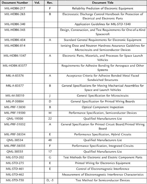
1.1.8. Summary of Military Aerospace Standards

Table 5.3 has a summary of military aerospace technical standards; some of these can be found at the following website: http://snebulos.mit.edu/projects/reference/MIL-STD/index.html.

1.2. Industry Standards

Even now industry standards for commercial spacecraft are either proprietary or broadly applicable to many industries. What follows are some of the more prominent standards that may figure into future commercial space programs.

1.2.1. Project Management

Guide to Program Management Body of Knowledge (PMBOK), Project Management Institute (http://www.pmi.org/Resources/Pages/Library-of-PMI-Global-Standards-projects.aspx). A global standard for the industry, which can help project management practitioners prepare for credential examinations, or assist organizations in creating and shaping their project management system. The PMBOK® Guide is not designed to function as a step-by-step, how-to book, but rather to identify that subset of the project management body of knowledge that is generally recognized as good practices. The Fourth Edition continues to reflect the evolving knowledge within the profession of project management. Like previous editions, it represents generally recognized good practice in the profession.

Table 5.2: Summary of NASA Standards

Document Number

Document Title

NASA-GB-8719.13

NASA Software Safety Guidebook

NASA-HDBK-1001

Terrestrial Environment (Climatic) Criteria Handbook for Use in Aerospace Vehicle Development

NASA-HDBK-4001

Electrical Grounding Architecture for Unmanned Spacecraft

NASA-HDBK-4002

Avoiding Problems Caused by Spacecraft On-Orbit Internal Charging Effects

NASA-HDBK-4006

Low Earth Orbit Spacecraft Charging Design Handbook

NASA-HDBK-5010

Fracture Control Implementation Handbook for Payloads, Experiments, and Similar Hardware

NASA-HDBK-5300.4(3J)

NASA Handbook Requirements for Conformal Coating and Staking of Printed Wiring Boards for Electronic Assemblies

NASA-HDBK-6003

Application of Data Matrix Identification Symbols to Aerospace Parts Using Direct Part Marking Methods/Techniques (Supersedes NASA-HDBK-6003b)

NASA-HDBK-6007

Handbook for Recommended Material Removal Processes for Advanced Ceramic Test Specimens and Components

NASA-HDBK-7004

Force Limited Vibration Testing

NASA-HDBK-7005

Dynamic Environmental Criteria

NASA-HDBK-8719.14

Handbook for Limiting Orbital Debris

NASA-HDBK-8739.18

Procedural Handbook for NASA Program and Project Management of Problems, Nonconformances, and Anomalies

NASA-SPEC-5004

Welding of Aerospace Ground Support Equipment and Related Nonconventional Facilities

NASA-STD-(I)-5005

Standard for the Design and Fabrication of Ground Support Equipment

NASA-STD-0005

NASA Configuration Management (Cm) Standard

NASA-STD-2202

Software Formal Inspections Standard

NASA-STD-2202-93

Software Formal Inspections Standard

NASA-STD-2818

Digital Television Standards for NASA

NASA-STD-3000 VOL I

Man-Systems Integration Standards, vol. I

NASA-STD-3000 VOL II

Man-Systems Integration Standards, vol. II

NASA-STD-3000 VOL III

Man-Systems Integration Standards, vol. III

NASA-STD-3001 VOL I

NASA Spaceflight Human System Standard, vol. 1: Crew Health (Superseding NASA-STD-3000, vol. 1, Chapter 7; and JSC 26882, Spaceflight Health Requirements Document)

NASA-STD-4003

Electrical Bonding for NASA Launch Vehicles, Spacecraft, Payloads, and Flight Equipment

NASA-STD-4005

Low Earth Orbit Spacecraft Charging Design Standard (Supersedes NASA-STD-(I)-4005)

NASA-STD-5001

Structural Design and Test Factors of Safety for Spaceflight Hardware

NASA-STD-5002

Load Analyses of Spacecraft and Payloads

NASA-STD-5003

Fracture Control Requirements for Payloads Using the Space Shuttle

NASA-STD-5005

Ground Support Equipment (Superseding NASA-STD-5005a)

NASA-STD-5006

General Fusion Welding Requirements for Aerospace Materials Used in Flight Hardware

NASA-STD-5007

General Fracture Control Requirements for Manned Spaceflight Systems

NASA-STD-5008

Protective Coating of Carbon Steel, Stainless Steel, and Aluminum on Launch Structures, Facilities, and Ground Support Equipment

NASA-STD-5009

Nondestructive Evaluation Requirements for Fracture Critical Metallic Components

NASA-STD-5012

Strength and Life Assessment Requirements for Liquid Fueled Space Propulsion System Engines

NASA-STD-5017

Design and Development Requirements for Mechanisms

NASA-STD-5019

Fracture Control Requirements for Spaceflight Hardware (Superseding NASA-STD-(I)-5019 (interim) and NASA-STD-5007)

NASA-STD-6001

Flammability, Odor, Off-gassing and Compatibility Requirements and Test Procedures for Materials in Environments That Support Combustion

NASA-STD-6002

Applying Data Matrix Identification Symbols on Aerospace Parts (Superseding NASA-STD-6002c)

NASA-STD-6008

NASA Fastener Procurement, Receiving Inspection, and Storage Practices for Spaceflight Hardware

NASA-STD-6016

Standard Materials and Processes Requirements for Spacecraft

NASA-STD-7001

Payload Vibroacoustic Test Criteria

NASA-STD-7002

Payload Test Requirements

NASA-STD-7003

Pyroshock Test Criteria

NASA-STD-7009

Standard for Models and Simulations

NASA-STD-8709.2

NASA Safety and Mission Assurance Roles and Responsibilities for Expendable Launch Vehicle Services; Revalidated/Reaffirmed 08/21/2003

NASA-STD-8719.10

Standard for Underwater Facility and Non–Open Water Operations

NASA-STD-8719.11

Safety Standard for Fire Protection

NASA-STD-8719.13

NASA Software Safety Standard (Rev B W/Ch1 of 7/8/2004)

NASA-STD-8719.14

Process for Limiting Orbital Debris (Baseline W/Ch 1 of 9/6/07)

NASA-STD-8719.17

NASA Requirements for Ground-Based Pressure Vessels and Pressurized Systems (Pv/S)

NASA-STD-8719.7

Facility System Safety Guidebook

NASA-STD-8719.9

Standard for Lifting Devices and Equipment; Revalidated/Reaffirmed 10/01/2007

NASA-STD-8729.1

Planning, Developing and Managing an Effective Reliability and Maintainability (R&M) Program

NASA-STD-8739.1

Workmanship Standard for Polymeric Application on Electronic Assemblies

NASA-STD-8739.2

Workmanship Standard for Surface Mount Technology (Baseline with Chapter 1 of 6/6/08); Revalidated/Reaffirmed 06/05/2008

NASA-STD-8739.3

Soldered Electrical Connections (Baseline with Chapter 3 of 6/6/08)

NASA-STD-8739.4

Crimping, Interconnecting Cables, Harnesses, and Wiring (Baseline with Chapter 4 of 7/25/08)

NASA-STD-8739.5

Fiber Optic Terminations, Cable Assemblies, and Installation (Baseline with Chapter 1 of 7/25/08)

NASA-STD-8739.8

Software Assurance Standard (Baseline with Chapter 1 of 5/5/05)

NSS-1740.12

Safety Standard for Explosives, Propellants, and Pyrotechnics

NSS-1740.14

NASA Safety Standard Guidelines and Assessment Procedures for Limiting Orbital Debris

Table 5.3: Summary of Military Standards That Might Apply to Spacecraft

image

image

image

The American National Standards Institute/Electronic Industries Alliance, Standard 748-B, Earned Value Management Systems (ANSI/EIA-748). The standard contains guidelines and common terminology for earned value management systems (EVMS). It also contains a discussion on the EVMS process, system documentation, and system evaluation sections that are informative sections providing application and implementation insight. Earned value management (EVM) is a technique for measuring project progress (http://en.wikipedia.org/wiki/Earned_value_management). EVM combines measurements of schedule and cost into integrated metrics that can give early warning of performance problems. EVM promises to improve the tracking of progress of the project and to keep the project team focused on achieving progress.

1.2.2. Systems Engineering

International Council on Systems Engineering (INCOSE) (http://www.incose.org/ProductsPubs/products/sehandbook.aspx), Systems Engineering Handbook, Version 3, of INCOSE Systems Engineering Handbook. This handbook represents a shift in paradigm toward global industry application consistent with the systems engineering vision. Developed for the new systems engineer, the engineer in another discipline who needs to perform systems engineering or the experienced systems engineer who needs a convenient reference, the handbook provides an updated description of key process activities performed by systems engineers.

The descriptions in this handbook show what each systems engineering process activity entails, in the context of designing for affordability and performance. On some projects, a given activity may be performed very informally (e.g., on the back of an envelope, or in an engineer’s notebook); on other projects, activities are performed very formally, with interim products under formal configuration control. This document is not intended to advocate any level of formality as necessary or appropriate in all situations.

ISO/IEC 15288:2008 (E) and IEEE Std 15288-2008. (See Chapter 6 in this volume on systems engineering in military projects.)

1.2.3. Fault Protection

Chapter 9, Long-Life Systems, pp. 671–690, in Siewiorek DP, Swarz RS, Reliable Computer Systems: Design and Evaluation, 3rd edition, contains several case studies that are instructive [1].

Jackson B, A Robust Fault Protection Strategy for a COTS-Based Spacecraft, 2007 IEEE Aerospace Conference. “This paper presents a robust fault protection strategy for a low-cost single-string spacecraft that makes extensive use of COTS components. These components include commercial processors and microcontrollers that would traditionally be considered inappropriate for use in space. By crafting an avionics architecture that employs multiple distributed processors, and coupling this with an appropriate fault protection strategy, even a single-string COTS-based spacecraft can be made reasonably robust. The fault protection strategy is designed to trap faults at the highest possible level while preserving the maximum amount of spacecraft functionality, and can autonomously isolate and correct minor faults without ground intervention. For more serious faults, the vehicle is always placed in a safe configuration until the ground can diagnose the anomaly and recover the spacecraft. This paper will show how a multi-tiered fault protection strategy can be used to mitigate the risk of flying COTS components that were never intended for use in the space environment” [2].

1.2.4. Mission Assurance and Safety

Quality Management Systems (QMSs)—The primary systems are ANSI/ISO/ASQ 9001 and AS9100 Quality Management System for Aerospace Industry; CMMI can also be used, particularly if the system has much software development. See the first chapter for more discussion about QMSs.

Company specific elements might include the following:

• Project safety evaluation checklist

• System safety program plan

• Safety assessment report

• Hazard report

• Requirements compliance assessment

1.2.5. Integration and Test

EMI/EMC—MIL-STD-461E is a rigorous standard, but it may not cover extreme frequencies or it may be too difficult to meet for some applications. Commercial standards for EMC are addressed in reference [3]. There are five primary bodies that generate relevant standards: the International Electrotechnical Commission (IEC), CISPR, the European Committee for Electrotechnical Standardization (CENELEC), the European Telecommunications Standards Institute (ETSI), and the Federal Communications Commission (FCC). The international community has worked to harmonize standards around IEC 61000-x set of standards.

1.2.6. Miscellaneous Industrial and Commercial Standards

American Society for Testing and Materials (ASTM)

ASTM E-595 2005, Standard Test Method for Total Mass Loss and Collected Volatile Condensable Materials from Outgassing in a Vacuum Environment

The Institute for Interconnecting and Packaging Electronic Circuits (IPC):

IPC-6011 1996, Generic Performance Specification for Printed Boards

IPC-6012 B 2004, Qualification and Performance Specification for Rigid Printed Boards

IPC-6013 A 2003, Qualification and Performance Specification for Flexible Printed Boards

IPC-6018 A 2002, Microwave End Product Board Inspection and Test

J-STD-001 C 2000, Requirements for Soldered Electrical and Electronic Assemblies

J-STD-004 A 2004, Requirements for Soldering Fluxes

J-STD-020 B 2002, Moisture/Reflow Sensitivity Classification for Nonhermetic Solid State Surface Mount Devices

J-STD-033 A 2002, Handling, Packaging, Shipping and Use of Moisture/Reflow Sensitive Surface Mount Devices

1.3. Commercial Off-the-Shelf

As more commercial ventures explore and exploit spaceflight, opportunities grow for the use of commercial off-the-shelf (COTS) modules and subsystems. Commercial components can greatly reduce cost and speed development. COTS provides access to a wide variety of high-performance components; the downside is that COTS almost never is radiation hard. The use of COTS modules and subsystems in spaceflight can be appropriate for short missions and low earth orbits. One example of the use of COTS in spacecraft was the LCROSS mission in 2009; another was the MiTEx mission in 2006.

“LCROSS is a fast-paced, low-cost, mission that leverages select NASA flight-ready systems, commercial-off-the-shelf components . . .” [4]. The LCROSS mission will have one portion of the spacecraft to observe another part of the spacecraft impact the moon; the goal is to identify substances, particularly water, on the moon. “The LCROSS science payload consists of two near-infrared spectrometers, a visible light spectrometer, two mid-infrared cameras, two near-infrared cameras, a visible camera, and a visible radiometer [4]”.

The Micro-Satellite Technology Experiment, or MiTEx, launched on June 21, 2006 into an elliptical geosynchronous transfer orbit. The Defense Advanced Research Projects Agency, Air Force, and Navy collaborated on this space mission to test technologies that could be incorporated in future military programs. Two major goals for MiTEx were to:

• “Investigate and demonstrate advanced space technologies such as lightweight power and propulsion systems, avionics, and spacecraft structures; commercial-off-the-shelf processors; affordable, responsive fabrication/build-to-launch techniques; and single-string components

• Demonstrate a one-year lifetime for small satellites built using these new technologies and techniques” [5]

The biggest problem with using COTS components is surviving radiation during spaceflight. This is a unique problem because vendors do not perform the reliability and radiation hardness analysis (RHA) on COTS components. As Barnes indicated, you cannot even leverage experience from other high-reliability users like the automotive industry because the total ionizing dose (TID) response depends on the specific fabrication process for the integrated circuits and single-event effects (SEE) depend on circuit design and its dimensions. Furthermore, packaging makes RHA hard to establish: analysis for SEE is difficult on plastic components and multichip modules are difficult to test. Finally, vendors typically change a fabrication process for integrated circuits, which then can reduce radiation tolerance, without informing customers of the changes or of the impacts to their applications [6]. There is no way of predicting radiation response for COTS components without testing them in an ionizing chamber, a nuclear reactor, or an ion beam accelerator.

Barnes suggests the following means to use COTS components for spacecraft:

• Establish RHA with radiation testing

• Disseminate radiation data to designers so they can use it early in project cycle

• Use various shielding techniques

• Use software and hardware mitigation methods

• Use modified commercial designs that are more radiation tolerant [6]

For missions that avoid areas of concentrated radiation, such as the South Atlantic Anomaly, COTS components stand a better chance for survival. If cost and reduced development time drive a mission, then you might tailor the mission to reduce radiation exposure; you can also use a combination of the suggested techniques, such as shielding and mitigation methods to reduce the effects of radiation.

Two other problems with COTS components are the use of prohibited substances (e.g., tin, zinc, cadmium) and counterfeit components. High tin content, particularly in solder, can lead to tin whisker growth and short circuits; you will need special equipment to detect these prohibited materials. Counterfeit electronic components, such as ICs, capacitors, and resistors, with poor quality standards have slipped into the supply chain and have caused major problems when component lots suffer widespread failures; signing up with the Government–Industry Data Exchange Program (GIDEP) can help you identify counterfeit or bad components.

Goodman’s summary for a project using COTS subsystems echoes similar experiences found in projects for unmanned spacecraft. “The Space Shuttle Program procured ‘off the shelf’ GPS and EGI units with the expectation that procurement, development, certification and operational costs would be significantly reduced. However, these projects consumed more budget and schedule than originally anticipated. Numerous and significant firmware changes were required to adapt these units for use on space vehicles. The promise of COTS products is most likely to be fulfilled when the intended application is close to or matches that for which the COTS product was originally designed. Independent verification and validation of receiver software, availability of receiver technical requirements to the Shuttle Program, open and frequent communication with the vendor, design insight and a rigorous process of receiver testing, issue investigation and disposition were keys to resolving technical issues with a complex unit. Modification of an aviation navigation unit for a space application should be treated as a development project, rather than as a ‘plug and play’ project under a fixed-price contract” [7]. Although this was written in 2002, it is still true, in large part, for current projects. A modified approach to COTS, where products are largely off-the-shelf but have the flexibility for some changes, still has promise to reduce cost and development time.

2. Company Processes

This section covers the processes relating to the regulations and standards listed previously, giving examples of how company processes comply with these requirements. Maintaining a consistent set of processes within an organization while serving the needs of many different customers often requires developing processes that cover the requirements from multiple sources. For example, NASA’s NPR 7120.5D calls for a particular review, but a DoD standard calls for another review that may have slightly different objectives or components. By developing an internal process that accommodates the requirements of both sets of these standards, a company can maintain consistency across projects within the organization.

To handle situations where a customer has a specific need or requirement not covered by a company’s standard process, a project may have to deviate from a prescribed process. In cases where a project has a legitimate reason for following a different process, it is necessary to obtain a waiver or deviation. A method for obtaining waivers or deviations is an essential part of any formal process management system. An example of such a process is also described in this section.

This section begins with project management, systems engineering, and fault protection processes. Subsequent topics include mission assurance, integration, test, and mission operations.

2.1. Project Management

Good project management forms the foundation of a successful project. Nearly all aspects of the implementation of a space mission fall under the responsibility and authority of the project manager. Therefore, establishing good project management processes is critical to mission success.

Most space mission projects begin with a notice from a sponsor in the form of an announcement of opportunity or a request for proposal (RFP). In some cases the opportunity may involve the production of multiple spacecraft to support an operational space-based capability. In others it may be just a single spacecraft designed to visit unexplored worlds in our solar system. The sponsor may include requirements about the organizational structure or type of development for the implementation of the project. For example, NASA’s Explorer, Discovery, Mars Scout, and New Frontiers Programs use an organizational structure in which the principal investigator (PI), a scientist, is ultimately responsible for delivering the proposed scientific results. Thus the PI has ultimate authority over the project. Such PI-led missions have been an effective way to implement successful space missions (e.g., Previous Studies on Lessons Learned from PI-Led Missions) [8]. Regardless of the type of opportunity, the solicitation notice initiates the competition between multiple organizations to propose the best solution and win the opportunity to fulfill the sponsor’s need. This proposal process begins with the formation of a project team and the first phase of the project, the concept formulation.

2.1.1. Project Organization: Team Roles and Responsibilities

One of the most important tasks of the project manager is the formation of the project team. As with any competitive endeavor, a successful team starts with a talented mix of players with diverse skill sets that bond together to achieve collective success. Each player has a role to play in reaching the common goal. Forming a team that will be dedicated to the mission from the start provides continuity and knowledge retention throughout the development. With a capable team that takes a vested interest in the project and a talented project manager to coach them, the team can achieve excellence beyond their expectations.

To operate efficiently and effectively, the team requires clearly defined lines of authority. The program or project manager is responsible for establishing those lines of authority and ensuring communication within the team. Documenting and distributing the project structure in the form of an organization chart and written definitions of the roles and responsibilities ensures that the members of the project team know what to do and where to get answers. A sample organization chart is shown in Fig. 5.4 and the responsibilities of individuals in the project organization are listed in Table 5.4.

2.1.2. Communication and Teamwork

In addition to clear lines of authority, communication and teamwork are essential to the successful implementation of a project. Regularly scheduled team status meetings provide an important forum for discussion of technical and programmatic progress. Depending on the phase of the project, the size and frequency of these meetings may vary. During the concept formulation phase, weekly meetings or teleconferences involving the entire project may be appropriate. During critical periods of integration and test, daily meetings of the integration and test (I&T) team are necessary. These meetings have peripheral benefits, too. In some cases, the meetings may spawn additional impromptu conversations afterwards leading to the resolution of other issues or potential problems.

image

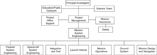
Figure 5.4: Project organization for a principal investigator (PI)-led mission.

Table 5.4: Roles and Responsibilities for a Principal Investigator (PI)-Led Mission

Role

Responsibility

Principal Investigator (PI)

The principal investigator is responsible for the overall success of the mission. He/she serves as the ultimate authority within the project for decisions that could affect the ability to deliver the science results. The PI sets the science goals for the mission and is responsible for developing the plan to meet those goals.

Project Scientist

The project scientist is responsible for implementing the science plan that was developed by the PI. He/she derives the measurement requirements from the science objectives. He/she also leads the science team and reports to the PI.

Education/Public Outreach (E/PO) Lead

The lead for E/PO is responsible for planning, developing, and coordinating programs to educate students and the public about the mission. The E/PO lead works closely with public relations regarding press releases and public events surrounding major mission milestones or accomplishments.

Project Manager (PM)

The project manager is responsible for formulating the project plan and implementing the project according to this plan. The PM reports to the PI. The PM establishes and coordinates the project office for the purpose of directing the project tasks and managing the project cost, schedule, and risk. The PM communicates the project progress/performance to the customer and conducts technical and programmatic reviews of the project.

Deputy Project Manager (DPM)

The DPM assists the PM with the project management responsibilities. In the event the PM is unable to fulfill his/her duties, the DPM may serve as the acting PM in his/her absence.

Payload Manager

The payload manager is a member of the project office and is responsible for the development of the payload. He/she works closely with the payload system engineer to deliver the required instrument performance on schedule and budget.

Project Office Support

The project office support includes a number of individuals in various areas of expertise. The project office supports the PM with skills necessary to perform scheduling, cost accounting, subcontracting, export control, and administrative tasks.

Mission Assurance Engineer (MAE)

The MAE (sometimes referred to as the performance assurance engineer) is responsible for the development and implementation of the mission assurance plan. The MAE oversees configuration management and enforces the quality standards for the project. MAE approval is required for the release of all project documentation and the closure of all issue reports.

Safety Engineer

The safety engineer reports to the MAE and is responsible for the implementation of system safety and personnel safety plans on the project. These plans include safety training, identification and mitigation of safety hazards, compliance with the range safety requirements, and developing the missile systems pre-launch safety plan (MSPSP).

Mission System Engineer (MSE)

The MSE serves as the lead technical authority on the project and reports to the project manager. He/she is responsible for developing the systems engineering management plan (SEMP) and managing the systems engineering team. The MSE handles the flow-down of the mission requirements to the mission elements. The overall requirements verification plan is also the responsibility of the MSE. The MSE conducts trade studies to evaluate various mission concepts and architecture options. He/she also monitors risks and identifies mitigations and reports recommendations to the PM. The MSE is responsible for managing all system budgets and margins on the mission. These typically include mass, power, RF link, alignment, guidance and control (G&C), data recorder space, downlink volume, etc. In some cases, tracking of these budgets may be delegated to a lead engineer. For example, the mass budget is often updated by the mechanical systems engineer.

Deputy Mission System Engineer (DMSE)

The DMSE assists the MSE in completion of mission system engineering tasks. In the absence of the MSE, the DMSE may serve as acting MSE.

Mission Software System Engineer (MSSE)

The MSSE is part of the mission systems engineering team. He/she is responsible for establishing the process and standards for all software development on the project, including both flight and ground applications.

Fault Protection Engineer (FPE)

The FPE, also part of the mission systems engineering team, is responsible for the development, implementation, and verification of the fault protections requirements. The FPE also coordinates the development of the onboard fault detection and autonomous responses.

Payload System Engineer (PSE)

The PSE is responsible for the requirements and verification of the instruments. He/she is responsible for coordinating with the MSE regarding the instrument interfaces and reports to the payload manager.

Instrument Lead Engineers

Instrument lead engineers are responsible for the technical development, cost, and schedule of their respective instruments. They report to the PSE.

Spacecraft System Engineer (SSE)

The SSE is responsible for the technical aspects of the spacecraft segment. He/she documents the requirements flow-down from the segment to the subsystems and is responsible for the verification of these requirements.

Subsystem Lead Engineers

Subsystem lead engineers are responsible for technical development, cost, and schedule of the spacecraft subsystem development. The lead engineer assignments are dependent on the spacecraft architecture. For example, some spacecraft may not have a propulsion system and therefore would not require a propulsion lead engineer. Common designations for subsystem lead engineers include structural, mechanical, thermal, power, command and data handling (C&DH), RF, G&C, propulsion, and flight software. Each lead engineer has specific responsibility with regard to her/his respective subsystem.

Launch Vehicle Coordinator (LVC)

The LVC is the project point-of-contact for all launch vehicle–related activities. This person participates in all meetings of the ground operations working group and the payload safety working group. The LVC is also involved in the trajectory review cycle and the coupled loads analysis. He/she is responsible for developing the launch vehicle interface requirements document, which documents the mission-unique requirements for the project.

Integration and Test (I&T) Lead Engineer

The I&T lead engineer is responsible for the integration and testing of the spacecraft and instruments. She/he leads the I&T team and coordinates the schedule of activities involving the spacecraft through launch.

Mission Operations Manager (MOM)

The MOM is responsible for managing the mission operations team and coordinating the in-flight activities on the spacecraft. He/she provides status updates for the project during the operations phase of the mission.

Ground System Engineer

The ground system engineer is responsible for the development of the hardware and software that makes up the ground system. She/he maintains the command and telemetry database and manages the development of many of the ground system software tools used by mission operations to perform the mission.

Mission Design Lead

The mission design lead is responsible for the development of the mission trajectory (or orbit) and associated parameters, such as launch date, C3 requirements, arrival date, and delta-V budget. He/she works with the LVC and LV provider in the trajectory review cycles.

When communications between team members can’t wait until the next scheduled meeting, knowing who to call and how to reach them is invaluable for solving problems quickly. Since some phases of spacecraft development, such as I&T, require work outside normal business hours, the ability to reach someone after hours could mean the difference between progressing to the next activity and losing a day of schedule reserve. For this reason, every project should maintain an up-to-date contact list, including the individual’s role and a work, home, and mobile phone number.

Another essential aspect of project communication is open dialog with the customer. Keeping the customer or sponsor informed of current progress, even when the news is bad, helps build a trusting relationship. Frequent communication can be used to alert the customer of issues which may be beyond the project’s control but that the customer could influence. For example, when the New Horizons project experienced an issue with a vendor component, NASA was able to change the delivery sequence of similar components from that vendor to another NASA project to minimize the schedule impact.

Various types of project communication are listed in Table 5.5. Internal communication types include: team meetings, technical interchange meetings, working group meetings, integration and test meetings (daily during I&T), website/network directories, and anomaly reports. Communications with the customer include project reviews and progress/status reports.

2.1.3. Work Breakdown Structure

The work breakdown structure (WBS) is a hierarchical representation of the work required to produce the products and services necessary to complete the project. Dividing the work into smaller deliveries helps facilitate the management of cost, schedule, and risk. NASA’s prescribed work breakdown structure as required by NPR 7120.5D is shown in Fig. 5.5.

The top level of the WBS represents the entire spaceflight project. The second level represents divisions at the segment level. The third level (not shown) is typically divided at the subsystem level for the spacecraft. Some segments, such as the spacecraft and payload, may lend themselves to a deeper level of division than other segments. There is flexibility to add elements to the WBS for products or services not covered in the existing elements. The work covered in each element is explicitly described in the WBS dictionary that accompanies the WBS. Every WBS must have a WBS dictionary that defines in prose the scope of work involved in each element. The WBS dictionary for the elements in Fig. 5.5 can be found in Appendix G of NPR 7120.5D.

Table 5.5: Example of Project Communication

image

image

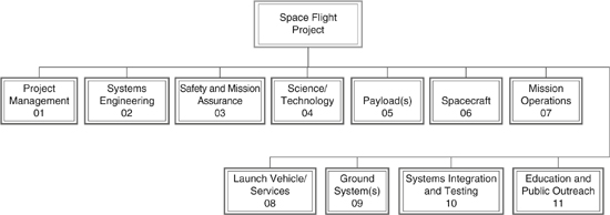
Figure 5.5: Example of a high-level WBS for spaceflight projects.

2.1.4. The Project Schedule

The project schedule is necessary for tracking the progress of the development to identify problems early while there is time to correct them. The schedule tracks the progress of the project using the same breakdown of tasks as the WBS. By tracking the work as it is completed along with the accounting of expenditures, the project can use the schedule to closely monitor the financial status of the project.

An effective method for measuring progress is earned-value management (EVM). The last chapter on systems engineering in military projects begins to address EVM. Good resources exist for EVM, such as the book by Eric Verzuh [9].

Commercial off-the-shelf (COTS) software tools for managing a large development schedule are readily available. Microsoft Project® and Primevera® are two examples. When multiple organizations are involved in a project, it may become necessary to convert file formats from different tools to update the project schedule status. Obstacles such as incompatibilities between scheduling tools could delay the incorporation of updated schedule status and potentially delay the identification of an issue. Enforcing standardization in the scheduling software can help increase the efficiency of schedule updates.

2.1.5. Project Phases

To enable the assessment of technical and programmatic progress of NASA missions, the project life cycle is divided into phases. Although NASA standards clearly define the mission phases, it can be advantageous to divide some of the longer phases into smaller periods to provide better visibility into the progress. Figure 5.6 illustrates a comparison of the project life cycle phases for various project management standards and how they are bounded by the major reviews of the project. The details of each of these phases are described in Table 5.6.

image

Figure 5.6: Comparison of various standards for mission phases.

Table 5.6: Project Phases for Spacecraft Development

Phase

Description

Pre-Phase A: Concept Formulation

Pre-phase A represents the period when advanced concept are studied. For NASA announcements of opportunity (e.g., for Discovery-class and New Frontiers-class missions), the development of the initial proposal is equivalent to the pre-Phase A period. During this phase, preliminary concepts are explored and trade studies conducted. This phase concludes with the production of a report or proposal describing the science objectives, measurement requirements, and the preliminary mission implementation plans.

Phase A: Concept Development

The activities conducted during Phase A include developing the technical and programmatic requirements and formulating the details of the implementation plan. For NASA announcements of opportunity, the development of concept study report is considered equivalent to Phase A.

Phase B: Preliminary Design

Phase B is the period when the preliminary design is completed and long-lead procurements are begun. Hardware breadboards of new designs are typically built and tested during Phase B. This phase concludes with the Preliminary Design Review (PDR) and the authorization to proceed from the formulation phases (Phases A/B) into the implementation phases (Phases C/D/E/F).

Phase C: Critical Design, Component Fabrication

Also referred to as “final design and fabrication,” Phase C marks the beginning of the hardware development and includes the fabrication and test of components and subsystems. Critical design concludes with the critical design review (CDR), after which component fabrication begins. For many projects, Phases C and D are merged as single phase in the project life cycle (Phase C/D), because the transition from Phase C to Phase D is not necessarily marked by a single event in time. For example, the schedule may show some Phase D activities, such as the “system assembly,” starting before all of the Phase C “component fabrication” activities are complete. So even though the activities conducted in each of the two phases are distinct, the transition in time between Phases C and D may not be distinct.

Phase D: Integration, Test, and Launch Operations

Also referred to as assembly, test, and launch operations (ATLO), Phase D represents the period when the spacecraft is assembled, tested, launched, and commissioned. Typically Phase D includes the 30 to 60 days of commissioning after launch.

Phase E: Operations and Sustainment

Phase E represents the primary mission operations phase. Often the mission operations phase is further divided into mission phases based on the trajectory and mission-critical events. For example, an interplanetary mission often refers to the long journey to the object of interest as the “cruise” phase. Upon arrival there would be increase activity during the “encounter” phase or the “orbit insertion” phase, depending on whether the event was a flyby or an orbital mission. These phase boundaries often represent changes in staffing requirements or changes in the complexity of operations. At the completion of the primary mission, the mission may be closed out or continue for an extended mission.

Phase F: Closeout

Phase F marks the end of the project by implementing the system decommissioning/disposal plan. If additional data analysis is required, it may take place during this phase.

2.1.6. Review Process

Reviews take place at many levels in a project, from detailed circuit board reviews and software code walkthroughs to major mission-level, project-wide reviews. As illustrated in the previous section (see Fig. 5.6), many of the major mission-level reviews form milestones or “gates” between project phases. Customer reviews during the early phases provide input to the selection process during competitive procurements. Later in the project life cycle, technical reviews benefit the project, because they can catch problems or potential problems that may have been overlooked by the development team. Reviews also provide the project with fresh insights from experienced reviewers for potential improvements and lessons learned.

Before going into the purpose and content of individual reviews, some key elements of any effective design review should be mentioned. Every review must have a review board with a chairperson. For small reviews this board may consist of only a few people, but for mission-level reviews the board may have as many as 10 or more members. The chairperson is responsible for selecting the board and conducting the review. To provide an independent viewpoint, the board members should not be involved in the design that is being reviewed. To allow time for a comprehensive review, the design review package should be provided to the review board at least 1 week prior (2 weeks is preferable) to the start of the review. The review package should contain the agenda and a summary of the requirements and the baseline design.

During the review, the chairperson is responsible for making sure that the agenda is completed, the minutes are recorded, and the action items are captured. After the review the chairperson distributes the minutes as a record of the review, including the date, the agenda, attendees, any major decisions, and the list of action items with assignments and due dates. Finally, it is the responsibility of project team to provide timely written response to each action item.

Major milestones illustrated in Fig. 5.6 are explained in Table 5.7.

Table 5.7: Major Project Reviews for Spacecraft Development

Review

Description

Red Team Review

A red team review is an independent review of a proposal draft for the sole purpose of improving the final proposal. It should be held when a complete draft of the proposal can be assembled. The review panel should consist of experienced reviewers from various disciplines, and the panel should evaluate the draft proposal using the same evaluation criteria that the customer will use to evaluate and score the final proposal. Receiving independent feedback that identifies potential weaknesses early helps the project team to strengthen their proposal and increase the probability of an award.

Proposal Document Review

This review represents the customer evaluation of the mission proposal. This review is performed at the conclusion of the pre-Phase A effort. In NASA’s announcement of opportunity process, the primary focus is on evaluation of the science, the science implementation strategy, and risk. The results of the evaluation factor into the “down-select” process. If selected, the project is awarded a contract for the next phase of the project (Phase A).

Concept Study Report Evaluation and Oral Site Visit Review

At the conclusion of the Phase A, the concept study report is evaluated according to the published evaluation criteria. The evaluation committee also conducts a site visit, during which members of the project team make oral presentations to the evaluators. The primary focus of this evaluation is to assess the risk associated with mission implementation. Results and recommendations from the evaluation team are used by the selecting official in the selection process.

System Requirements Review (SRR) Program/System Requirements Review (P/SRR)

The purpose of the SRR is to demonstrate that the decomposition of the requirements from the mission objectives is sufficient to proceed with the development of the design concept and performance specifications. This review typically occurs during Phase A. Topics covered in the SRR include the following: Mission objectives and success criteria Mission requirements Performance requirements Programmatic requirements Functional requirements of mission segments (payload, spacecraft, launch vehicle, mission operations, ground system, mission design and navigation) Results of tradeoff studies Mission drivers Contract deliverables Open trades and issues Lessons learned In some cases, the SRR and the conceptual design review are combined into a single review.

Conceptual Design Review (CoDR)

The purpose of the CoDR is to assure that the proposed implementation will meet the mission requirements. The focus is on the proposed design concept and major interfaces. The CoDR should be held early enough that changes can be made without major impacts to the project. Topics covered in the CoDR include the following: Mission overview, including objectives and mission success criteria Changes since the proposal Action item closure status System performance requirements System constraints System drivers Proposed design approach for mission segments (payload, spacecraft, launch vehicle, mission operations, ground system, mission design and navigation) Major system trades Technical and programmatic interfaces Project risks and mitigations System redundancy System margins System heritage Integration and test plan Ground support equipment Mission assurance and system safety plans Lessons learned The results from the CoDR form the basis for the preliminary design (Phase B). In some cases the concept study oral site-visit review is substituted for the CoDR.

Preliminary Design Review (PDR)

The PDR is the first detailed review of the system design. The focus of the review is on demonstrating that the design meets all system requirements with an acceptable level of risk and within the cost and schedule constraints. The results from the PDR form the basis for proceeding with the detailed (i.e., critical) design (Phase C). The topics covered in the PDR include the following: Mission overview/project overview, including mission objectives, mission success criteria, launch dates, mission phases, key mission milestones) Project status, schedule, management metrics Project risks and mitigations Action item closure status Changes since the last review System performance requirements and specifications System interface specifications (with preliminary interface control documents [ICDs]) System budgets and margins (mass, power, communication link, data storage, processor throughput, processor memory usage, attitude control, alignments, etc.) Spacecraft subsystem descriptions Structural design and analysis Electrical systems design and analysis Software requirements and conceptual design Fault management design Design heritage Verification plans Integration and test flow Ground system and ground system equipment (GSE) design (mechanical and electrical GSE) Launch vehicle interfaces Mission operations plans Electromagnetic interference (EMI) control plans Contamination control plans EEE parts processes, quality control, quality processes, and inspections


Plans for failure modes, effects, and criticality analysis (FMECA), fault tree analysis (FTA), probabilistic risk assessment (PRA), reliability/redundancy analyses Preliminary safety analysis (hazard identification) Orbital debris assessment Documentation status Lessons learned

Confirmation Review/Non Advocate Review (NAR)

The NAR is often conducted as part of the PDR. This part of the review provides the customer with an independent assessment of the readiness of the project to proceed to the next phase of development (Phase C).

Critical Design Review (CDR)

The CDR is the most comprehensive project-level review of the detailed system design. The focus is on demonstrating that the detailed design will meet the final performance and interface specifications. At the time the CDR takes place, all actions from previous reviews should be closed, or there is a good rationale for why they remain open. Most drawings should be ready for release. The material covered should revisit all items listed for the PDR plus the following additional items: Final implementation plans Detailed hardware block diagrams showing signal and power interfaces and flow Detailed software diagrams showing logic, task communication, and timing Completed design analyses (loads, stress, torque, thermal, radiation) Design and expected lifetime Engineering model/breadboard hardware/software test results Released ICDs (spacecraft, payload, launch vehicle) Test verification matrix System functional, performance, environmental test plans Ground operations (including during launch campaign) Transportation plans, shipping container design Results of the planned analyses such as FMECA, FTA, PRA, reliability/redundancy analyses Hazard analyses and safety control measures Single-point failures list Spares philosophy The results from CDR form the basis for fabrication, assembly, integration, test and launch of the flight system (rest of Phase C, Phase D).

Mission Operations Review (MOR)

The purpose of the MOR is to demonstrate that the mission operations plans are sufficient to conduct the required flight operations to achieve the mission objectives. This review is the first of two major prelaunch reviews focused primarily on the ground system and mission operations (the second is the operations readiness review, described below). The MOR is held before the major integration and test activities, such as environmental test. The MOR should include the following topics: Mission overview, including mission objectives, mission success criteria, launch dates, mission phases, key mission milestones Spacecraft overview, including subsystem descriptions Schedule status, including status of documentation and procedures Mission operations risks and mitigations Mission operations and ground system action item closure status Mission operations objectives, including launch and early operations Mission operations plans and status (payload and spacecraft) Mission operations staffing, training, and facilities Onboard data management and data flow diagrams Health and safety monitoring, contingency operations Data trending Configuration management Operations functional process flow (planning, control, and assessment) Ground system requirements, design, and status Ground software Operational interfaces Flight constraints Prelaunch tests plans and status (tests, simulations, exercises) Payload operations and data analysis Documentation status Launch critical facilities Lessons learned Issues/concerns

System Integration Review (SIR)

The SIR assesses the readiness to begin integration and test of the system. This review is held before the start of integration and test. The material covered in this review include integration and test plans, verification and validation plans, status of flight system components and associated procedures, ground equipment status, and staffing plans.

Pre-Environmental Review (PER)

The purpose of the PER is to show the flight system and ground support equipment are ready for environmental test and that the plans and procedures are complete and comprehensive. This review is held before environmental test and includes the following: Project overview and status Action item closure status Changes since the last review Closure status of problems, anomaly reports, deviations, and waivers Test objectives, descriptions, plans, procedures, and flow Test facilities, equipment, instrumentation Pass/fail criteria Test verification matrix Contamination control safety Thermal vacuum profile with test Component-level test history/results Baseline comprehensive performance test results Failure-free operating hours Documentation status Calibration plans Open issues and concerns

Preship Review (PSR)

The PSR serves to confirm that the spacecraft has successfully completed all environmental testing and is ready to be shipped to the launch site. The PSR takes place after environmental test and before shipment. The PSR should include the following: Project overview and status Action item closure status Closure status of problems, anomaly reports, deviations, and waivers Risk assessment of any open items Compliance with test verification matrix Comparison of measured margins to estimates Trending data Failure-free operating hours Transportation plans, shipping container, ground support equipment Launch site operations Status of safety approvals for launch site operations

Launch Vehicle Readiness Review (LVRR)

The LVRR certifies that the project is ready to proceed with integration of the launch vehicle with the spacecraft. Typically, the LVRR is held before the mission readiness review and is chaired by the launch services program manager.

Mission Readiness Review (MRR)

The MRR certifies that the project is ready to move the spacecraft to the launch pad.

Flight Readiness Review/Mission Briefing (FRR)

The FRR is held to close out any issues or actions from the LVRR and to certify that the launch vehicle is ready to start the launch countdown. This review is held about 3 days before the opening of the launch window and is chaired by the NASA launch manager.

Launch Readiness Review (LRR)

The LRR is held to close out any issues or actions from the FRR and certify that the project is ready to start the launch countdown. At this review the certification of flight readiness is signed. The LRR is held no later than 1 day before launch and is chaired by the space operations assistant associate administrator or may be delegated to the launch services program manager.

Operations Readiness Review (ORR)

The purpose of the OOR is to demonstrate the flight system, ground system, and operations team are ready for launch. In some cases this review may be called the mission operations readiness review (MORR) or the flight operations review (FOR). This review is held near the completion of the pre-flight testing and include the following information: Final launch, operations, and commissioning plans Mission operations procedures (nominal and contingency operations) Flight and ground system hardware and software characteristics Personnel and staffing User documentation

Lessons Learned Exercise (LLE)

LLEs are held to capture and document knowledge from experiences of the project team. This activity helps preserve knowledge and improve processes. These exercises are held periodically or after major events.

Post Launch Assessment Reviews (PLAR)

PLARs are held to assess project performance after significant events or accomplishments. For example, a commissioning review, where results of the spacecraft and instrument commissioning activities are presented, is an example of a PLAR.

Critical Event Requirements Review (CERR)

Prior to critical events, such as a trajectory correction maneuver (TCM) or other major operation, a CERR, is held to confirm that the requirements are well understood and the event can be accomplished with an acceptable level of risk.

In addition to the major project-level reviews described in Table 5.7, peer reviews of components and subassembly designs are also a key part of the technical review process. In these peer reviews, component test plans are checked to ensure that all requirements are met. At these lower levels of assembly, more of the details of the designs and tests are evaluated.

Implementing good review practices help make any review more productive. Every review should have a review chair, who is responsible for selecting the review committee and conducting the review. The review chair should be experienced in the subject matter and independent from the members of the team presenting the review. For project-level reviews, the review chair is selected from individuals outside the project and often outside the organization. For some projects, the review chair of project-level review may be a member of the sponsor organization. For subsystem-level peer reviews, the chair may be part of the project, but must be independent from the team implementing the design under review. In general, the objective of the review is to evaluate whether the design meets the requirements. To achieve that objective, the requirements must be documented and the team must have selected a single design. In advance of the meeting, the agenda and presentation material must be supplied to the review committee with sufficient time to prepare for the review. This time may vary depending on the amount of material involved in the review. Typically, a week or more is required for a project-level review. During the review, meeting minutes and action items must be recorded. After the meeting, the minutes should be distributed and the action items tracked to closure.

image

Figure 5.7: One example for closing out an action item.

Closing an action item requires a procedure or process; Fig. 5.7 illustrates one example for closing an action item. An action time may lead to a minor correction or it may force a major design change or it may prove intractable and force a major change in the mission or re-evaluation. A record of all action items and their disposition should be archived in the project depository or database.

image

Figure 5.8: Risk management process from NASA NPR 8000.4.

2.1.7. Risk Management

The purpose of risk management is to identify potential problems early so that mitigation strategies may be implemented in time to minimize the impact to the project. The project manager is responsible for developing and implementing the risk management plan, but all members of the project team are involved in the risk management process. Risk management is a continuous process throughout all phases of the project, and it spans all aspects of the project. The risk management process, as defined in NASA NPR 8000.4, involves a number of steps in a cycle: identification, analysis, planning, tracking, controlling, communication and documentation. Figure 5.8 illustrates the risk management cycle.

Risks in production have much greater variability than operational risks. Human involvement in production introduces and maintains that variability. The risks occur in all stages of the life cycle of a product. The obvious stages are design, fabrication, assembly, test, shipping, installation, and maintenance. Some of the problems might include (but this is not necessarily a complete list):

• Late ordering and shipping of components and materials can delay delivery of the final product.

• Incorrect design and development of circuits can lead to incorrect operation of the final product.

• Incorrect design and development of software can lead to incorrect operation of the final product.

• Incorrect fabrication of materials can lead to incorrect operation of the final product.

• Incorrect assembly of components can lead to incorrect operation of the final product.

• Incorrect test procedures that miss desired or true measured values or that damage the equipment from incorrect power or signal levels.

• Mechanical damage from dropping, hitting, cutting, over flexing, bending, poking, or splashing with corrosive substances.

• Electrical short, over-voltage, over-current, or electrostatic discharge (ESD) from receiving personnel or from other subsystems connected to ecliptic subsystems.

Risk identification, the first step in the process, involves the identification and documentation of potential undesirable events and associated impacts to the project. The documentation of the risks should include all necessary information to provide a complete understanding by someone who has no prior knowledge of context of the risk. The identification of risks can come from many sources, including team members, reviewers, the lessons learned from other projects, and safety and reliability analyses.

Risk analysis (also called risk assessment) is the assignment of risk factors, on the basis of established criteria, to the likelihood that a risk will occur and to its consequence if it does occur. These criteria may vary from project to project and may depend on the type of risk being analyzed. For example, safety-related risks are often ranked with a lower tolerance on the probability of occurrence (i.e., they must be less likely to occur) than are technical or cost related risks. In addition to the likelihood and consequence, the time frame within which action is required is also documented for use in prioritizing the risks. Examples of likelihood and consequence guidance are given in Tables 5.8 and 5.9. A method for ranking risks is shown in Fig. 5.9. Risks whose likelihood and consequence put them in the far right corner (red) of the matrix in Fig. 5.9 are given the highest priority, followed by those in the center of the matrix (yellow), and finally those in the far left corner (green). Some methods for assigning risk factors include engineering judgment, statistical analysis, and probabilistic risk assessment.

Risk planning involves the development of strategies to mitigate risks and identify trigger dates when decisions must be made. For example, a new design may offer the promise of better performance, but it may also be a greater risk to the project schedule than an existing design. A mitigation strategy for the late delivery of the product could be to incorporate a decision point in the product schedule that would require a particular milestone to be met or the older, less-risky design would be built instead. In some cases a mitigation strategy might include multiple options with different trigger dates.

Table 5.8: Example of Risk Likelihood Assessment Guidance

image

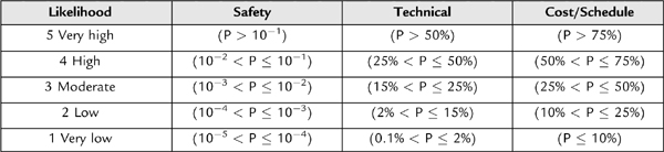
Table 5.9: Example of Risk Consequence Assessment Guidance

image

image

Figure 5.9: An example of risk severity ranking guidance.

Risk tracking involves the monitoring of risks and gathering of new information that could affect risk plans or other aspects of the risk management process. This new information is used to evaluate the risk management performance and is incorporated into updated reports of risk status and trends.

Risk control involves the decisions made based upon existing and new risk-related information. In some cases the decision may be to continue following the planned strategy for a particular risk, which may lead to the execution of the associated contingency plan. In other cases, the decision may be to re-assess the risk and plan for alternative mitigations strategies. Finally, if a risk has been successfully mitigated, the residual risk can be accepted and the risk closed.

Risk communication and documentation, as Fig. 5.8 shows, is the core of the risk management process. The importance of disseminating the risk information throughout the project so that the entire team is aware of potential issues cannot be understated. In some cases, an individual on the project team may think of a mitigation strategy that has gone unnoticed. In other cases, knowledge of a particular risk may lead a team member to discover a previously unidentified risk. By communicating risks to the sponsor or customer, a project may open options that had been considered unavailable. Documenting and communicating risk information also provides a record of the rationale for risk-related decisions made during the project. A risk management plan fulfills this need for documenting and some of the need for communication.

A project’s spares philosophy is an example of an important risk mitigation strategy. Purchasing spares is necessary in any spaceflight development effort. Determining how much is enough is a complex tradeoff between cost and benefit. One of the factors in this trade involves the amount of downtime that can be tolerated in the event of a failure. If the mission is designed for an operational capability with little or no downtime, it may be necessary to launch multiple spacecraft so that spare spacecraft are waiting on orbit in the event of a failure. This approach would be a costly solution. Alternatively, a mission that doesn’t need on-orbit spares but that has a very narrow launch window without a backup opportunity may need to be able to recover from a fault on the launch pad within a short period of time. This could drive the need to have fully qualified spare components ready and waiting for installation on the spacecraft. Finally, if a particular mission has many launch opportunities throughout the year, the spares philosophy may be simply to have minimal set spare parts so that repairs can be made to existing boards in the event of a failure. An organization’s ability to build or repair certain types of parts may also affect the project’s spares philosophy. An organization with a complete manufacturing facility may be able to divert resources during a crisis to expedite a particular repair or develop a replacement part. It would likely take longer for an organization without on-site facilities to obtain the necessary repairs quickly. An organization without on-site facilities might choose to develop spares at higher levels of assembly, such as at a board- or box-level.

..................Content has been hidden....................

You can't read the all page of ebook, please click here login for view all page.
Reset
3.137.178.133