
11 Analyzing SIM Cards
Previous chapters covered procedures, seizure, and collection of physical and digital evidence on a mobile device. The next several chapters discuss the analysis of the data within the device files and folders. In this chapter, you’ll learn about the subscriber identity module (SIM) card, once used only in GSM devices but now found in CDMA devices, and the evidentiary data that may reside within the file system.
SIM cards contain information that can be used by an examiner to locate a device, identify contacts, and see a user’s communications. The examiner will need to concentrate on the card’s file system—not an easy task, especially because SIM cards often store data in a different format than mobile device file systems and in various locations with different security levels. Nevertheless, the SIM card is well documented, which ensures that the manufacturers and cellular communication companies have a clear set of instructions regarding how to communicate within the GSM/UMTS network. The pertinent standards and documents are discussed throughout this chapter and can be referenced often if the examiner’s case involves the analysis of a SIM card.
This chapter covers SIM and UICC (Universal Integrated Circuit Card) smart cards, the SIM file system, and the various artifacts that may be used in any investigation. This chapter does not cover all of the files and folders available on a SIM, because many of these are used strictly for network communication—hundreds of files are contained on a single SIM, and covering them all within a single chapter is not possible. You can find more information by consulting the materials mentioned throughout the chapter.
Smart Card Overview: SIM and UICC
The European Telecommunications Standards Institute (ETSI) defines smart cards as “micro-processor equipped tokens, able to store and process a diverse range of data and applications” (www.etsi.org/technologies-clusters/technologies/smart-cards). Many examiners use the terms “UICC” and “SIM” interchangeably, though, strictly speaking, UICC (Universal Integrated Circuit Card) is the latest generation of the SIM card. The UICC is the hardware portion of the smart card, while the SIM, USIM, and others are software applications included on the card. Initially, a SIM was used only for GSM networks as the key to the mobile device operating on a cellular network along with both the hardware (mobile device) and software component.
UICCs now are used in most smart devices, including CDMA devices. UICC covers the gamut of subscriber cards to include the removable user identity module (R-UIM) and CDMA2000 subscriber identity module (CSIM) cards, also part of the CDMA devices that can be used globally.
All the applications on the UICC are defined by ETSI and adopted by the Third Generation Partnership Project (3GPP). Applications (such as USIM, SIM, ISIM, and CSIM) contain information and help with flow of information to the mobile device depending upon the network used. If HSPA (High-Speed Packet Access), HSPA+, and LTE (Long-Term Evolution) networks are used in conjunction with the USIM, the ISIM handles the high-speed packet access (HSPA). If a UMTS network is being used, the USIM application will maintain control of communication and includes the data needed to help the device operate on that network; if a 2G or Enhanced Data rates for Global Evolution (EDGE) connection is needed on a GSM network, the SIM application would be used. A SIM card containing only a SIM application cannot operate on a UMTS-only network, but a UICC with both the SIM and USIM application can operate on either a GSM or UMTS system.
The physical size of a UICC is described in ETSI TS 102 221; version 14.2.0 references both ISO/IEC 7816-1 and ISO/IEC 7816-2 for acceptance. The most significant change to the UICC has been the size of the smart card; Figure 11-1 shows the various size progressions of the card. The sizes are defined by ETSI as 1FF ID-1 UICC, 2FF Plug-in UICC, 3FF Mini-UICC, 4FF Nano-UICC, and M2M Form Factors (MFF1/MFF2) (embedded UICC). The ID-1 UICC was never used in a mobile device because of its large size (that of a credit card), but the Plug-in UICC is the most commonly referenced and was used in feature phones and early smart devices until 2004. The Mini-UICC was then released and made its way into most smart devices until the Nano-UICC was released in 2012 and adopted in newer iOS, Android, BlackBerry, and Windows Phones. The MFF1/MFF2, or embedded UICC, is a SIM typically soldered directly to the device’s PCB and used for machine-to-machine (M2M) applications. The benefits are many and include longer life and ease of moving from one carrier to another because of over-the-air provisioning—not a change of UICC. MFF2 are utilized in many automobile infotainment systems, point of service (POS) systems, tablets, wearables, and IoT devices. ETSI has since released TS 103 383 outlining the eUICC (e-SIM) concept and its current use in today’s businesses and devices. The eUICC should pose a unique problem with traditional mobile forensic examinations. Subsequently, Apple has expressed the most interest in using eUICCs within all of its products, from iPhones to iPads.

FIGURE 11-1 The evolution of SIM/UICC size
The actual microprocessor did not change between the SIM and Nano-UICC, but the shell that contains the microprocessor has changed. There was a debate between ETSI and Apple on Apple’s ability to change the size of the microprocessor, and Apple finally won. Most UICC cards that are used in today’s devices are still the original size for feature phones, but the majority of smart devices use the Nano-UICC.
SIM Card Analysis
Mobile forensic software replicates commands used by the mobile device to communicate with the applications on the UICC. The software can collect various data files using application protocol data unit (APDU) commands. These commands communicate with the mobile device and the UICC to obtain and store data by writing information to the UICC. A UICC is passive and does not initiate contact with the mobile device to begin a transaction; instead, it stands by to listen for the APDU commands sent from the mobile device. A mobile device, or the operating firmware on the mobile device, can request the device serial number, the last SMS message, and even the last known location. By replicating APDU commands when using mobile forensic software, the examiner can also request this information to be used for the investigation.
Before we move into the communication methods from the software solution to the UICC, you should understand the physical characteristics of a UICC. The UICC comprises a microprocessor (CPU), RAM, ROM for firmware, and Electrically Erasable Programmable ROM (EEPROM) for nonvolatile storage. The UICC accepts communication via the I/O contact point (Figure 11-2) from the mobile device, but to operate correctly, the UICC needs all points in contact with the mobile device terminal pins. The UICC surface is contacted by the six or eight points along reciprocal contact points on the mobile device—most UICCs in today’s devices have six or eight pins. Reading, querying, and writing to the UICC occurs at these contact points (6 pin: VCC, GND, I/O, VPP, RST, and CLK / 8 pin: VCC, GND, I/O, VPP, RST, CLK, SIM_PRESENCE, and GND).
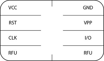
FIGURE 11-2 UICC smart card contact points: communication to the chip occurs via the I/O contact, which is the pathway to the UICC CPU.
As mentioned, the UICC is a passive part of the mobile device and must be contacted with APDU commands for action to occur. An APDU command comprises two components: a command and a response, as shown in Figure 11-3. The command is always initiated outside of the UICC (from forensic software or mobile device firmware), and a response is always returned, even if a command is incorrect. The UICC’s response can indicate that a command was successful, unsuccessful, successful with security problems that must be addressed, or successful with a return of data.

FIGURE 11-3 APDU command and response structures
An APDU command first needs to navigate the SIM card file system using INS (instruction) commands on the way to the appropriate file ID. During the navigation, if any security or permissions need to be satisfied, they, too, will have to be entered as APDU commands. Security conditions for SIM cards are referred to as ADM (Administrator) or CHV (Card Holder Verification). Once at the file ID, the APDU command must send an instruction (INS) that will tell the SIM what is to occur at the file ID. The instruction codes that can be used in an APDU are outlined in ETSI TS 102 221 (www.etsi.org/deliver/etsi_ts/102200_102299/102221/08.02.00_60/ts_102221v080200p.pdf). A file ID must then be “selected” to include additional instructions. To “select” a file ID, the APDU command must include A4 as the INS code. The ID for the file to be acted upon, if using the select INS, would then fill the Data portion of the command structure shown in Figure 11-3. Whatever the length of the data portion in bytes, this number will be added to the Le block of the command. A file ID is made up of 2 bytes, and its specifications are outlined in ETSI TS 131 102 and 3GPP TS 31.102.
The commands that would be issued to a UICC to retrieve the integrated circuit card identifier (ICCID) using a command APDU are shown in Figure 11-4. The first commands navigate to the ICCID via the file system, identifying the file and then sending the instruction code to read the number of bytes located within the record. The return command contains the ICCID indicating success. The ICCID is in a “reverse nibble” format (each byte is flipped to create the actual value—for example, 21 80 48 would be 12 08 84). Response codes are also listed within ETSI TS 102 221. This is the same process forensic software will use to read the UICC ICCID. The reading of various portions of the UICC is covered later in the chapter in the section “User Data Locations.”

FIGURE 11-4 APDU commands to navigate and read the ICCIC
File System UICC Structure
Obtaining the file system of all pieces of evidence is the goal of an examination, and it’s the same with UICCs. Most information on the UICC is used for network communication and authentication, but the card can also contain valuable user information. Most mobile forensic solutions can obtain a UICC file system, with a few known exceptions—MOBILedit Forensic and Susteen Secure View obtain user data directly from the UICC and import the information into the user interface. Some solutions even query the UICC through the handset rather than via a secondary SIM card reader. This section will not cover these tools, but it will include the artifacts that can be found within the file system and their formats.
![]()
The examiner will benefit from working through the UICC file system manually in the same way a forensic solution would work automatically. Understanding the method in which an automated tool obtains the data from these smart cards is an important feather in the mobile forensic examiner’s cap, and it’s a necessity for an examiner who wants to be an expert in mobile forensics.
Understandably, today’s mobile devices contain little user information, simply because the data transmitted and received with a smart phone far exceeds the limited storage capacity of the UICC. However, mobile devices, including smart devices, can still store user data to the UICC that would otherwise be missed if the smart card were not examined. It is critical that the examiner obtain a full file system collection from the SIM/UICC, and I always recommended that the UICC card be collected and examined outside the body of the device, no matter the device, for reasons that include but are not limited to network location, networks accessed, subscriber information, SMS, contacts, and calls, to name a few. Some “fileIDs” that are discussed later are not extracted because of their protection status. Each of these records can also contain information that an automated tool either cannot parse or does not parse correctly, so manual inspection is sometimes necessary.
The UICC file system is made up of several levels that contain four types of files: a Master File (MF) and Dedicated Files (DF), which include Application Dedicated Files (ADF), and Elementary Files (EF). There is only one Master File on the UICC, and it is analogous to the root folder of a computer file system. The file ID of the MF is 3F00. There can be several DFs on the UICC (for example, GSM, DCS1800, TELECOM, USIM, PHONEBOOK), and these are analogous to a directory on a computer and files that are identified and described by ETSI TS 151 011 and 3GPP 51.011. The partitions on a SIM have always been described in forensic circles as SIM, USIM, CSIM, and ISIM (LTE, HSDPA+), but in reality they are applications that are used depending upon the type of network that is accessible.
![]()
SIM partitions are actually applications, and within the applications are various files that are referenced by what is commonly referred to as “file IDs.”
If a CDMA system is available, the CSIM partition/application is used, but if a UMTS system is available and preferred, the USIM partition/application is used. The UICC file system can be confusing, with several layers within each application and folder system, some containing duplicated information. This information is duplicated in the file system view but is actually written only once to the smart card, as is clearly observable when using the UICC file ID system. The file ID system simply references the needed record within the application. Because the UICC storage space is finite, a reference to this information must be made, and then, within the application, a pointer to the file ID is made. As mentioned, file IDs for most UICC data are defined and outlined within ETSI TS 131 102 and 3GPP TS 31.102. This does not mean that a file can be on the UICC only if the file ID is defined and listed by ETSI, however. In fact, a file can be created on a UICC that is specific to a particular carrier and used only by the carrier within its supported mobile devices. This is another reason the examiner should make sure to do a file system collection of all UICCs encountered.
![]()
If a UICC contains multiple partitions/applications, it is important to examine each referenced area, because a USIM application can contain additional phonebook entries over and above those in the SIM application.
Network Information Data Locations
Many files reside on the UICC card, most of which are network related. Generally, most files within the file system can be examined manually if needed. They contain information used by the mobile device to communicate on the network in a format that makes sense only to the network of the carrier system engineer. However, the examiner should be aware of several of these network-related files on the UICC when conducting a mobile device examination because they often contain data that could be used in a mobile device investigation.
Some files, such as the ciphering key (Ki), although important and necessary for the authentication process and contained on all SIM cards, are unavailable to the forensic examiner using any forensic software. Although some files are not available for examination, they should still be recognized and their existence documented.
ICCID
The ICCID is analogous to the serial number of the UICC; it represents the unique number assigned to that single UICC—that is, no other smart card on the cellular network uses the same unique number. Typically, this number is located on the exterior of the smart card, but not always. The number can be a maximum of 20 digits. The ICCID must always be available to the mobile device without limitation, primarily because this number will be used for the authentication process. This means that even if a UICC is locked with a PIN, the ICCID can be ascertained, and the examiner can then use the ICCID to obtain the PIN unblocking key (PUK) to change the PIN and access the UICC contents by sending the carrier of record the appropriate court order.
![]()
The “authentication process” is involved in accepting the subscriber onto a cellular network so that calls, data, and other transactions can occur. Without a successful authentication process, the mobile device will be unable to use the cellular network. Emergency service calls are an exception, however.
Table 11-1 shows valuable information such as the size, number of bytes, file ID, and additional information about the ICCID and its contents. Figure 11-5 shows the actual representation of the ICCID on the exterior of the UICC, and Figure 11-6 shows the output of the ICCID using mobile forensic software. The ICCID is stored in a reverse nibble format within the record found directly under the Master Files in EF_ICCID. So when the examiner is decoding the ICCID, each byte must be reversed to interpret the ICCID digits properly.
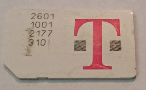
FIGURE 11-5 UICC exterior with a visible ICCID
![]()
FIGURE 11-6 Decoded ICCID
TABLE 11-1 TS 102 221 Information on the ICCID
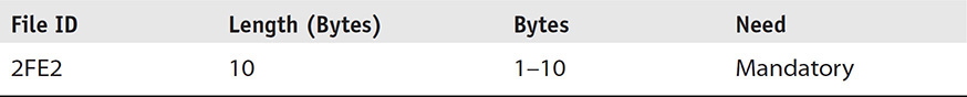
The ICCID is made up of 10 bytes that comprise several values. The first two digits are the system code, a constant value for mobile devices, 89, which represents ISO 7812, “Telecommunications Administers and Private Operating Agencies.” The next two or three digits represent the country code for the UICC. For the United States, the country code is 01. The next two or three digits represent the Issuer Identifier Number, which for a mobile UICC is analogous to the first two digits on a credit card that identify the credit card issuer (such as Visa or MasterCard), but for the UICC it would be T-Mobile, AT&T, Vodaphone, and so on.
![]()
To find other country codes, refer to https://en.wikipedia.org/wiki/Mobile_country_code or consult international numbering plans at www.numberingplans.com.
The first three data groups cannot exceed seven digits. The remaining digits represent the UICC number and are made up of the year and month of manufacturing, configuration specs, and the unique UICC number. The final digit is referred to as the checksum digit.
Consider, for example, the ICCID number 89310170105113168601:

IMSI
The International Mobile Subscriber Identity (IMSI) is the unique number that identifies the subscriber on the cellular network. This number is used to find a subscriber across the network and deliver calls, data, and other transactional information. Often, examiners think the phone number of the device is important to a cellular network. But it is the IMSI, for both GSM and CDMA networks, that is needed for contact to be made. This is an important file and should always be reported during the investigation. In fact, this record can be used to subpoena the records of the subscriber.
The IMSI is a protected file, and as such, if the UICC is locked with a PIN it will be inaccessible. The IMSI, under GSM/UMTS standards, will be 9 bytes, but the subscriber number can be a maximum of 15 digits. This is an interesting concept when the examiner recognizes that the total number of digits equals 18 when looking at the raw hexadecimal values under EF_IMSI in the UICC file system. The values are also stored in reverse nibble, with the first byte as the length, which will always equal x08. The preceding bytes compose the IMSI in reverse nibble, and in order to decode the digits, you must first reverse them; the first digit, which will always be 9, should be dropped because it is not part of the IMSI value but is a placeholder (that looks surprising when added to the length byte 89, indicating telecommunication like the ICCID). Table 11-2 shows information on the IMSI and its contents.
TABLE 11-2 TS 151 011 Information on the IMSI

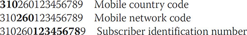
Much like the ICCID, the digits within the IMSI represent data to the examiner. The first 3 bytes are the mobile country code (MCC), the next two digits are the mobile network code (MNC), and the remaining digits are the subscriber identification number. The following shows the extracted IMSI using mobile forensic software and the breakdown of the IMSI number. Consider, for example, the IMSI number 310260123456789:
LOCI
The location information (LOCI) is an elementary file under the DF_GSM (DF structure for GSM) that identifies the geographic area where the device was last successfully powered off. The last portion of the sentence is critical: The LOCI writes the last tower location to which the device was registered when a successful power-off occurred so that the device can access the network quickly upon powering on. If the device’s battery is removed, if it is not powered off correctly, or if the device is broken prior to powering off, this file may not be available or may be incorrect. If, in fact, the LOCI file contains data, the examiner can use this key to identify the geographic location by contacting the carrier of record with the key information. The LOCI comprises the TMSI (temporary mobile subscriber identity), LAI (location area information), TMSI time, and the location update status.
The TMSI, as indicated by its name, is a temporary random ID that is assigned via the VLR (visitor locator register) to the subscriber; the actual IMSI is not sent out via the handset because of possible capture and identification of the mobile subscriber, and the temporary IMSI changes when the device moves to a different VLR. The LAI comprises the MCC (mobile country code), the MNC (mobile network code), and the LAC (location area code). By consulting the web site www.mcc-mnc.com, the examiner can at least identify the country and carrier to contact to obtain possible subscriber information. Table 11-3 shows the identifiable information for the LOCI, and Figure 11-7 shows an example from an actual GSM device.

FIGURE 11-7 LOCI and interpreted information from a mobile forensic solution
TABLE 11-3 TS 151 011 Information on the LOCI

FPLMN
Forbidden Public Land Mobile Network (FPLMN) is an elementary file under DF_GSM that identifies networks with which the device carrier does not have a valid agreement to access. In other words, a PLMN (both MCC and MNC) will be written to the FPLMN if the network rejects the location update, because PLMN is not allowed. This elementary file once had a limit of four records, but with the new UICC specification, it can hold up to n records, depending upon the card manufacturer and carrier specifications. When a record is added to the FPLMN elementary file, that record is placed after the last record; if there are no additional slots, the first record is removed and the new record is added to the last available slot.
In terms of value for the examiner, the FPLMN identifies specific country codes along with the carrier of record, which could also identify a geographic region in which the mobile device was being used or attempted to access. If a user, for example, had stated that he was not in a certain country and admitted to having control of the mobile device, but access was attempted to a forbidden network in the country the user denied being in, an argument could be made that the user was indeed within the country. This information could be based upon the evidence located within the FPLMN elementary file. Table 11-4 shows the technical information regarding the FPLMN format.
TABLE 11-4 TS 151 011 Information on the FPLMN

User Data Locations
When examining the information from a mobile device UICC, forensic applications primarily focus upon personal data that could be stored on the SIM. With the storage capacity of today’s mobile devices, the storage of personal data to the UICC is not the norm. Mobile device settings default to storage to the handset, and a user would have to change the storage location settings manually for the UICC to be used. Because the capacity of a SIM is finite, as set by standards, along with the mass amount of personal data that is transmitted and received by a mobile device, the storage of data that can be used for investigations is limited. Previously, the portability of a UICC could enable users to take their SIM with them, complete with their contacts and SMS messages, place the SIM into another GSM device, and be able to be up and running with their personal information, subscriber information, and network details. With the movement to world phones that cover the necessary cellular bands globally, there is no need to have multiple devices to cover a particular cellular band using the singular UICC. Because the need for portability is no longer a necessity, carriers and phone manufacturers alike no longer store data to the UICC by default. This does not dismiss the importance of collecting the UICC content, however.
Mobile forensic tools concentrate on several areas to recover this personal data within the UICC, as listed in the following section. The examiner should understand the location, format, and structure of these areas to help validate the recovery of the automated mobile forensic software solution. Again, understanding how an automated tool identifies, converts, and displays mobile device data will satisfy another step in your becoming a mobile forensic expert.
SMS
The Short Message Service (SMS) is another elementary file located on the UICC. It contains several records that define many aspects of the message and service. Either 3GPP TS 23.040 or ETSI 123 040 for UMTS defines these records as messages that either originate from the mobile equipment (ME) or are received from the subscriber’s network. The record length cannot be more than 176 bytes, with the first byte being a status of the record and the remaining bytes making up the architecture of the message. Table 11-5 shows the file information obtained from ETSI 123 040 with specific information on the format for EF_SMS files.
TABLE 11-5 TS 151 011 Information on the SMS

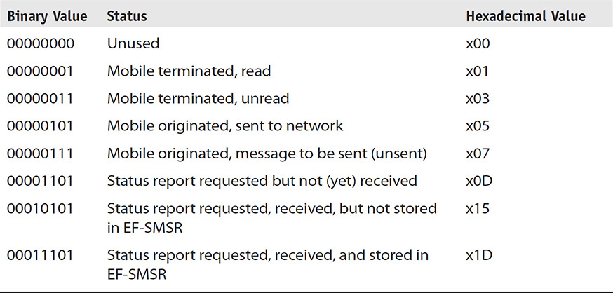
The status byte of the record, shown in Table 11-6, will tell the examiner several interesting facts. If the status byte indicates “Unused” and content is still contained within bytes 2–176, the examiner should assume, with great certainty, that the message has been deleted. The ME simply changes the status of the record and does not remove the content. Since the status shows “Unused,” the record slot is available and thus can be overwritten with a new message, but until that time the record is available to be recovered by the examiner. The status byte can assist in an investigation if the SMS was alleged to have been sent, but did not have service, or if it had been submitted but was rejected by the network and was never delivered. Using the status byte, an examiner can make this determination.
TABLE 11-6 Message Status Byte from ETSI TS 131 102 V9.5.0 (2011-01)
![]()
It is important that the examiner understand that the recovery of “slack space,” or partial SMS messages, from a SIM card is not possible because of the way a record is written to the card. When an SMS message is submitted to be 281written to a SIM card and an open “unused” slot is identified, the 176-byte record is then written to the SIM. It does not matter if the message occupied only 56 bytes; all 176 bytes will be written to the record, overwriting any record that had previously existed. When is SIM card is written to, it is all or nothing.
Bytes 2–176 make up the content with a set length for the actual message content depending upon how the data is formatted; this is often referred to as the Transport Protocol Data Unit (TPDU). The TPDU contains a variety of data, depending upon whether the message was sent (SMS-SUBMIT) or received (SMS-DELIVER). For an SMS-SUBMIT message, Table 11-7 shows the various types of data stored within the TPDU. For an SMS-DELIVER message, the content differs slightly, as shown in Table 11-8. Each type of content is covered in the following tables with specific comments and explanations for better understanding.
TABLE 11-7 -SUBMIT Structure from TS 100 901

TABLE 11-8 SMS-DELIVER Structure from TS 100 901

The breakdown, description, and decoding of the TPDU are covered in the following list:
• Length of SMSC (Short Message Service Center) information This is the number of octets (8 bits or 1 byte) that will be used to store the type of number and also the number of the service center. Typically, SMS-SUBMIT messages have the value 00, which indicates the use of the service center number internal to the mobile device. Not all handsets have this value, and if it is missing, it means the SMSC will be obtained from the handset along with the TON/NPI and service center number.
• Type of number and numbering plan indicator (TON/NPI) This single octet indicates the type of number that the preceding telephone number will represent. This byte is representative of the binary number created, with the first bit always 1, and is combined with the TON, which is 3 bits, and the NPI, which is 4 bits. Table 11-9 represents the various combinations and values for TON and NPI values. Once the correct hexadecimal number is located, the number will be converted to a binary number that will be used to decipher the type of number and number plan used in the message. For example, a common value is x91, which, when converted to binary, is 1 001 0001 and will indicate that a plus sign (+) is attached to the number in front of the country code. Using Table 11-7, the examiner would be able to confirm that this number is an international number conforming to the ISDN/telephone numbering plan by dropping the first MSB (always 1), decoding the following 3 bits for the TON and the remaining 4 bits for the NPI.
TABLE 11-9 Binary Representation of TON/NPI Key of SMS Messages

• Service center number This value is the representative number of the service center that was used to route the SMS message. This value per ETSI TS 123 040 V12.2.0 (2014-10) is stored in semi-octets in binary-coded decimal (BCD) format, as defined in GSM 44.008 and again in ETSI TS 124 008 V11.8.0 (2013-10). This format is also reverse nibble. Often, the numbering does not complete an octet, so an F is added to complete the octet.
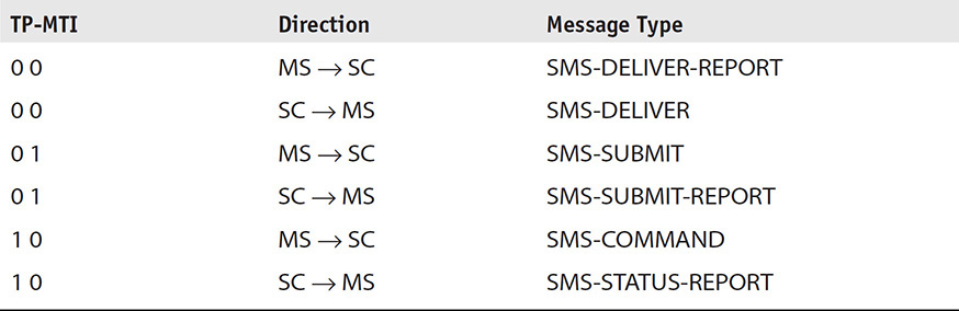
• First octet of Short Message Transfer Protocol (SM-TP) This single byte indicates the type of message from the six defined types in ETSI GSM 03.40. This hexadecimal byte should be converted to binary, and the two least significant bits are used to determine the type of the SMS message. Table 11-10 lists the various types of messages that are identified by the two least significant bits (1, 0) in the first octet of the SM-TP message. These bits are referred to as the TP-MTI (message type indicator).
TABLE 11-10 Binary Representation of SM-TP Byte of SMS Messages, which Indicates the Message Protocol Used
• Address length A single octet represents the length of the actual sender number. This byte will need to be converted to decimal to obtain the number of nibbles that are represented by the telephone number. Unlike the SMSC length, this value will not include the following byte that indicates the TON/NPI.
• Type of Number and Numbering Plan Indicator (TON/NPI) Table 11-9 can again be used to determine the number plan type and type of number of the sender.
• Sender number The sender number is again in semi-octets or reverse nibble (BCD), as was the case with the service center number.
• TP-Protocol-Identifier (TP-PID) This octet will identify the protocol that has been used for the transmission of the message. For standard ME-to-SC communication, this value will most likely be 00 as defined by ETSI TS 123 040 V12.2.0 (2014-10).
• TP-Data-Coding-Scheme (TP-DCS) This octet represents the coding that has been used to encode the message. This value will assist the ME in decoding the format once received. As with all other values, this octet, when converted to binary data, can be interpreted to determine the value. In Table 11-11, values are given as represented in 3GPP 3G TS 23.038 V2.0.0 (1999-06). Most often, the value for the TP-DCS will be 00 to indicate that the default 7-bit data code scheme will be used. However, in countries such as China, Korea, Japan, and others that use characters outside the ASCII range, this value will be different, because UCS2 will most likely be used. An example would be x04 in the TP-DCS section of the SIM record. The x04 in binary would be 01 00, which indicates 8-bit data and class 0 message.
TABLE 11-11 Binary Representation of TP-DCS Byte of SMS Messages, which Indicates the Data Coding Protocol Used

• TP-Service-Center-Time-Stamp (TP-SCTS) This value is represented by semi-octets and reverse nibble (BCD) in the ordering of Year, Month, Day, Hour, Minute, Second, and Timezone. The Timezone is the number of quarter hours from the local time to GMT time, and the most significant bit of the first octet indicates whether the number is positive or negative GMT. The Timezone is significant because if the ME has knowledge of the local time zone, the ME can display the received time in the local format. The time zone and time are local to the sending entity, which is important for the examiner to understand, especially when time and date are critical to the case.
• TP-User-Data-Length (TP-UDL) This integer value, represented in hexadecimal, is the length of data that is contained within the message. This value is also determined by the TP-DCS, or data format, discussed earlier. If the TP-DCS is the default, 7-bit is the length represented by septets (2 bytes), and 8-bit and UCS2 are represented by octets (1 byte). After converting this number into a decimal value, the examiner can identify the length of the message data immediately following as displayed in octets.
The message maximum length set by standards is 140 bytes. If the message is formatted using the 7-bit GSM alphabet, the records shall not exceed 160 characters. However, if the message is formatted using 8-bit, the record content shall not exceed 140 characters. To make matters more confusing, when you’re examining SMS output and UCS2 coding (Unicode) is used in the message content, the message length cannot exceed 70 characters using the 16-bit UCS2 alphabet format. All formats are documented in 3GPP TS 23.038. The various coding formats for the message allow for the transmission and reception of messages in multiple languages and also messages with more than the default 140 characters. The 7-bit or the GSM alphabet as defined by 3GPP TS 23.038 is the default format and is mandatory for network providers, but countries that use languages not supported by the extended ASCII table of the GSM alphabet (China, Korea, Japan) use the UCS2 (16-bit) format. The ME will always default to the 7-bit format, but as soon as a character is entered that is not part of the 7-bit GSM alphabet, the entire message is re-encoded into UCS2.
• TP-User-Data (TP-UD) The user data portion of the SMS contains the message in 7-bit, 8-bit, or UCS2 format as specified in the TP-DCS. This data is represented in forensic tools as hexadecimal values.
• TP-Message-Reference (TP-MR) The single octet is included in sent messages that indicate the integer value of a message reference. This value will typically be x00 but can be a value from 0 to 255.
Both SMS-SUBMIT and SMS-DELIVER use a combination of the items outlined in this section and others outlined in ETSI TS 123 040. Figure 11-8 shows an actual SMS-DELIVER message, and Table 11-12 describes the values and decodes the data in the figure. These illustrations can assist the examiner in locating key artifacts within the SMS message that are typically observed in a UICC file system extraction.
TABLE 11-12 Corresponding Values with Figure 11-8 with Decoded Data for Values Listed from an Actual Message


FIGURE 11-8 Actual hexadecimal message from an SMS message
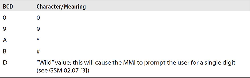
Notice that sometimes characters are within BCD values and must be interpreted as a 0, but in Table 11-13, the extended BCD characters are identified. These can be seen within HEX values throughout SIM records.
TABLE 11-13 Extended BCD Values
Contacts
Contacts on a UICC are referred to as Abbreviated Dialing Numbers (ADN). This elementary file is located on a SIM application under DF_Telecom and can also be under DF_Phonebook on a USIM application. Before the UMTS and USIM applications, the SIM contained only a single phonebook located under DF_Telecom, where it still is today on the UICC. When the USIM application was added to the UICC, two phonebooks were possible. For an examiner, this often led to problems when using a software solution that was unable to obtain both the USIM and SIM applications’ stored data. This was typically nontransparent to the examiner and often went unnoticed. Today, mobile forensic solutions support both application phonebooks.
Often these phonebooks coexist and contain duplicate records, but it is entirely possible that the records under DF_Phonebook on the USIM are unique and accessible only by reading the DF_Phonebook on the USIM application. The phonebook located on the USIM application is under the DF_Phonebook, which is under DF_Telecom. This is referred to as the global phonebook. Multiple phonebooks are available under the DF_Telecom/DF_Phonebook and can be application-specific. This means that a single phonebook under DF_Phonebook can be used by a single application on the mobile device up to 250 record entries. UICCs with the DF_Phonebook can hold thousands of contact names and numbers, and this dedicated file should be investigated. The contacts located under the USIM and SIM application under DF_Telecom/EF_ADN hold a maximum of 250 records and are duplicated between applications (see Figure 11-9). Contacts can be located in several places within a mobile device’s UICC, but the information that can be stored is much different from what is observed within the contacts storage location of a smart phone (such as photos, addresses, and usernames).

FIGURE 11-9 Both the USIM and SIM applications can hold ADN records; one EF_ADN will be duplicated between the USIM and SIM.
Like other data on the UICC, the data within the ADN record is coded in a semi-octet (BCD) format with the possibility of an alpha identifier, which is a name associated with the listed phone number. When an alpha identifier is used, the format, as specified by standards in 3GPP TS 23.038, will be 7-bit GSM alphabet, left justified, and all unused bytes will use FF or UCS2 format. The alpha identifier can be 0 to 242 bytes in length, and the rest of the record, to include the ADN length, TON/NPI, ADN, configuration record, and extension record, must be 14 bytes.
Much like the SMS record, the ADN will be coded in BCD format, preceded by the length of the ADN and the TON/NPI. The length is much like the SMS embedded address length discussed previously. Using Table 11-9, the Type of Number and Numbering Plan Indicator (TON/NPI) can be determined by the examiner before decoding the actual ADN that immediately follows. The ADN, as previously indicated, is coded in semi-octets or BCD format just like the service center and sender number in the SMS records. The balance of the ADN, if larger than 20 characters, will be written to an extension file under EF_EXT1 and is indicated in the last byte of the ADN record. The preceding byte, called the configuration record or capability record, can indicate whether additional configuration or capabilities are needed for the call and points to a record in the EF_CCP1 file. The complete breakdown of an actual record in an EF_ADN record is shown in Table 11-14.
TABLE 11-14 Abbreviated Dialing Number (EF_ADN) Are Contacts in Both the USIM and SIM Applications

It is extremely important that the examiner understand the layout and limitations of storage within an ADN record, because overflow of data could reside within another file that the forensic software quite possibly will miss. It is also important to examine the UICC to locate data not recoverable or missed by forensic software. For example, if a record from the EF_ADN is deleted, because EF_ADN does not employ a status byte, the entire record is overwritten with FF when the record is deleted from the SIM. A deleted contact is not recoverable. However, records in the DF_Phonebook do not have to be contiguous, and noncontiguous records could indicate that the record was deleted before another contact could be added to the phonebook. This could be valuable information for the investigation.
Fixed Dialing Numbers
A UICC contains a phonebook that can be set to allow only numbers within the EF_FDN to be dialed from the mobile device. This phonebook, once activated, is protected by Card Holder Verification 2 (CHV 2), often called PIN 2, which must be entered to access and edit information. By the user disabling the EF_IMSI and EF_LOCI functions of the device for any other number, the mobile device cannot call any numbers other than what is included in the fixed dialing list. Of course, emergency numbers can operate without a SIM inserted into a mobile device, so this does not affect emergency services when dialing out. The EF_FDN is located under DF_Telecom in both the SIM and USIM applications.
Companies, and often parents, can restrict a mobile device to allow only specific call-out numbers but still receive incoming calls. At times, this is also used to store a phonebook that is protected by a layer of security. This enables a user to conceal a set of names and numbers and, in essence, creates a secret phonebook. As an investigator, being aware of the location of the EF_FDN is important, because no mobile forensic solutions currently check the fixed dialing numbers elementary file.
The layout of the EF_FDN is exactly the same as that of the EF_ADN with one exception: if the record exceeds the size allotted for the record, the overflow will be stored in EF_EXT2 instead of EF_EXT1 as with EF_ADN records.
Call Logs
A UICC stores only the last numbers dialed (LND) and does not store incoming calls to the ME’s SIM memory. Incoming calls would be stored on the device itself. The elementary file LND is located under DF_Telecom in both the SIM and USIM application. The LND record is similar to the EF_ADN in the storage capacity and data layout. The LND record can store an alpha identifier (name), a byte to identify the length of the phone number, a byte for TON/NPI, the actual dialing number in BCD format, a configuration/capability byte, and finally the extension byte.
The EF_LND has limited records, depending on the carrier, but typically no more than ten records can be stored to the UICC. When a new call is made and all records are occupied, the first record is removed and all records then shift up, with the new record taking the last position. Most of today’s mobile devices do not store the call history directly to the mobile device, but it is important for an examiner to understand the format, layout, and location of this valuable data should it be populated.
Dialing Number
The dialing number for the mobile device is not necessarily important to the mobile carrier; the carrier relies on the EF_IMSI to identify the mobile user within the network, so a dialing number does not necessarily need to be stored on a UICC. If during an examination the EF_MSISDN is not located on the UICC, this does not indicate that the device was not used or is not in service. As described, the ability for a mobile device to use the cellular network is not dependent on the MSISDN, and only a valid EF_IMSI is needed. However, the EF_MSISDN is located under the DF_Telecom for both SIM and USIM applications on a UICC. The EF_MSISDN can include several records within the file, depending upon the carrier. Multiple EF_MSISDN records enable the user of the UICC to have a phone number for a business, personal use, fax, or other, with only a single EF_IMSI. This enables the device to be associated to multiple dialing numbers depending on which number was called.
The format structure for the EF_MSISDN and records is the same as that of the EF_ADN and should be used if the records are to be decoded manually. Figure 11-10 shows the EF_MSISDN records and first record of an actual UICC.

FIGURE 11-10 The MSISDN within the file system, its data, and decoded data
The UICC contains a large number of files that can be examined and verified (see Figure 11-11). It is just a matter of how important the UICC file system might be to the examination.

FIGURE 11-11 File system view of a UICC card and the many folders available to the examiner
Chapter Summary
UICC cards in today’s devices might not contain a massive amount of user-related data, such as SMS, contacts, or last numbers dialed. However, the UICC is always needed by a GSM/UMTS when operating on a cellular network.
Even though a UICC is unable to hold data such as videos or other large files, it can hold hundreds of files within the card’s file system and applications. Because the UICC must always be inserted into the device while operating on the cellular network, some type of evidence can always be collected—it might be information on last location, networks used, or the vital IMSI needed to crack a case. The UICC should never be neglected in any investigation.
![]()
Remember that CDMA devices also must always use a UICC when operating on the GMS/UMTS band.
The UICC data storage methods and structure are clearly documented by standards. This type of documentation can be used to help the examiner understand how to interpret the information contained on the UICC if the forensic software is unable to recover the data or the type of data is not supported.
This chapter introduced the examiner to the decoding of SMS, ADN, LND, IMSI, and ICCID, among other key artifacts. This information will be critical when examining other file system data contained within feature phones and today’s smart devices. A lot of the storage formats, such as 7-bit and reverse nibble, are used throughout the industry, and understanding them will aid the examiner in other decoding exercises within the book and also during actual mobile device investigations.