Appendix C
Coordinated MultiPoint (CoMP)
C.1.1 Partial Joint Processing
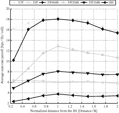
In Figure C.1, the average sum-rate per cell obtained by the different transmission schemes is plotted when moving away from one of the Base Stations BSs of the cluster.
Figure C.1 Average sum-rate per cell versus normalized distance for M = 6 UEs and an edge-of-cell SNR of 15 dB (Thiele et al. 2010)
C.1.2 Dynamic Base Station Clustering
In this section, a technique is highlighted in which the Base Station (BS) clusters are created in a dynamic way, that is, in each time slot t the sets of coordinated BSs are generated in order to maximize a given objective function (Boccardi et al. 2008). Such an approach can be seen as an extension of Papadogiannis et al. (2008), with the difference that User Equipments (UEs) and clustering are jointly selected in order to maximize the weighted sum rate.
In order to describe the scheme, let us define ![]() as the set of BS indexes belonging to the nth cluster at the time slot t and
as the set of BS indexes belonging to the nth cluster at the time slot t and ![]() as the set of UE indexes scheduled for transmission in a given cluster at the time slot t. Define
as the set of UE indexes scheduled for transmission in a given cluster at the time slot t. Define ![]() and
and ![]() respectively as the BS clustering and UE allocation at the tth time slot. For sake of clarity we drop the dependence on the time slot t. The physical layer technique is then described by the antenna weights
respectively as the BS clustering and UE allocation at the tth time slot. For sake of clarity we drop the dependence on the time slot t. The physical layer technique is then described by the antenna weights ![]() and the power allocation
and the power allocation ![]() , and with these definitions we denote the throughput achievable in the nth cluster with
, and with these definitions we denote the throughput achievable in the nth cluster with ![]() . Scheduling, BS clustering, calculation of the beamforming coefficients and power allocation are realized in a Central Unit (CU), which could be a new physical node or one BS acting as the CU.
. Scheduling, BS clustering, calculation of the beamforming coefficients and power allocation are realized in a Central Unit (CU), which could be a new physical node or one BS acting as the CU.
The proposed technique can be summarized as follows:
- Phase I Each BS sends the channel estimates to the CU.
- Phase II Based on the Channel State Information (CSI) and on the scheduling requirements, the CU jointly creates the clusters of collaborating BSs, schedules the UEs in these clusters and calculates the beamforming coefficients and the power allocation.
- Phase III The CU sends to the BSs beamforming coefficients, power allocation, indexes of the coordinated cells and indexes of the selected UEs. At this point, the BSs belonging to the same cluster need to share the data of the selected UEs between them.
With respect to full network coordination (Centralized Joint Processing (CJP)), the proposed technique allows the reduction of signaling due to data sharing, while requiring the same amount of signaling due to channel estimates exchanges.
The problem of joint clustering and UEs selection can be formalized as follows
The objective function ![]() is a function of both the BS clusters and of the UEs scheduled in each cluster. For example, under a Zero Forcing (ZF) precoding assumption the optimum must at the same time minimize the intercluster interference and select a quasiorthogonal set of UEs to be scheduled in each cluster. The two constraints are related respectively to the assumption of nonoverlapping clusters and to the assumption that each UE cannot be served at the same time by BSs belonging to different clusters.
is a function of both the BS clusters and of the UEs scheduled in each cluster. For example, under a Zero Forcing (ZF) precoding assumption the optimum must at the same time minimize the intercluster interference and select a quasiorthogonal set of UEs to be scheduled in each cluster. The two constraints are related respectively to the assumption of nonoverlapping clusters and to the assumption that each UE cannot be served at the same time by BSs belonging to different clusters.
The optimal solution of (C.1) requires a brute force search over the sets of UEs and possible BS clusters. In the following we propose a suboptimal approach based on the idea of restricting the search space. This approach consists of two different stages, an offline stage and an online stage.
Offline phase The candidate clusterings are chosen off-line taking into account path loss and shadowing, and more generally also average UEs distribution and average channel estimates.
Online phase At each time frame t the central node estimates the weighted sum rate achievable for each cluster. This sum-rate estimation involves the choice of a candidate set of UEs to be scheduled, with a brute force UE selection or with a greedy UE selection technique, and the calculation of the power allocation. Finally, the clustering that maximizes the weighted sum-rate and the associated set of UEs, beamforming coefficients and power allocation are used for transmission in the tth time slot.
To evaluate the scheme, a system simulator has been used with 19 single antenna BSs and wraparound, 30 UEs per BS, and edge-of-cell Signal to Noise Ratio (SNR) of 15 dB. Each single-antenna UE is dropped with uniform probability inside each cell. Fairness is guaranteed by a Proportional Fair (PF) scheduler. The reference SNR is defined as the SNR at the cell vertex. The channel has been modeled considering Rayleigh small-scale fading and path loss, with path loss exponent equal to 4.5. Cf. WINNER+ (2009b) for further simulation details. The results are shown in Table 6.3.
C.2 Coordinated Beamforming and Scheduling
C.2.1 Decentralized Coordinated Beamforming
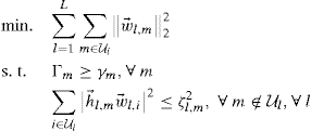
Let us assume that each UE is equipped with a single receive antenna. Hence the channel matrix between the UE m and BS l, ![]() is reduced to a vector and will be denoted
is reduced to a vector and will be denoted ![]() . Going from Equation 6.3, the receiver precombining SINR of UE m can be shown to be given by
. Going from Equation 6.3, the receiver precombining SINR of UE m can be shown to be given by
Note that full carrier phase synchronization is assumed between all BSs ![]() that serve a given UE m. Note that, for fixed
that serve a given UE m. Note that, for fixed ![]() , the constraints of (6.10) can be expressed as a generalized inequality with respect to the second-order cone (Bengtsson and Ottersten 2001; Boyd and Vandenberghe 2004; Wiesel et al. 2006) and (6.10) can be solved as a Second Order Cone Programming (SOCP). The generalized formulation shown in (6.10) can accommodate multiple scenarios ranging from coherent multicell beamforming with
, the constraints of (6.10) can be expressed as a generalized inequality with respect to the second-order cone (Bengtsson and Ottersten 2001; Boyd and Vandenberghe 2004; Wiesel et al. 2006) and (6.10) can be solved as a Second Order Cone Programming (SOCP). The generalized formulation shown in (6.10) can accommodate multiple scenarios ranging from coherent multicell beamforming with ![]() (in the extreme case
(in the extreme case ![]() ) to the coordinated single-cell beamforming case where
) to the coordinated single-cell beamforming case where ![]() . Note that the formulation above needs a complete channel knowledge of
. Note that the formulation above needs a complete channel knowledge of ![]() between all pairs of m and l, and hence, it requires a centralized solution.
between all pairs of m and l, and hence, it requires a centralized solution.
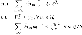
In the following, the decentralized method proposed in Tölli et al. (2011) is briefly summarized, where the beamformer vectors are obtained locally relying on coupled real-valued intercell interference parameters exchanged between adjacent BSs. For simplicity, attention is paid to the coordinated single-cell beamforming case, where ![]() .
.
The intercell interference term from BS l to UE m is denoted as ![]() , and the term with inequality is relaxed as
, and the term with inequality is relaxed as
C.3![]()
The SINR formula in (C.2) is modified as
(C.4)
where the index of serving BS for UE m is denoted as ![]() , and
, and ![]() . Now, (6.10) can be reformulated for the special case
. Now, (6.10) can be reformulated for the special case ![]() as:
as:
where the optimization variables are ![]() ,
, ![]() ,
, ![]() and
and ![]() . The second constraint in (C.5) guarantees that the intercell interference generated from a given BS l cannot exceed the UE specific thresholds
. The second constraint in (C.5) guarantees that the intercell interference generated from a given BS l cannot exceed the UE specific thresholds ![]() .
.
Observe that the BSs are coupled in the SINR constraints in (C.5) by the interference terms ![]() . If the interference terms were fixed, (C.5) would be decoupled and the transmitted power could be separately minimized at each BS. Next, the coupled SINR constraints are addressed by introducing local auxiliary variables and additional equality constraints. Thus, the coupling in the SINR constraints is transferred to coupling in the equality constraints, which can then be decoupled by dual decomposition (Boyd et al. 2007; Palomar and Chiang 2006). The decoupling is further simplified by the fact that each intercell interference term
. If the interference terms were fixed, (C.5) would be decoupled and the transmitted power could be separately minimized at each BS. Next, the coupled SINR constraints are addressed by introducing local auxiliary variables and additional equality constraints. Thus, the coupling in the SINR constraints is transferred to coupling in the equality constraints, which can then be decoupled by dual decomposition (Boyd et al. 2007; Palomar and Chiang 2006). The decoupling is further simplified by the fact that each intercell interference term ![]() couples exactly two (adjacent) BSs, that is, the serving BS
couples exactly two (adjacent) BSs, that is, the serving BS ![]() and the interfering BS l. Thus, it is enough to enforce the two local copies to be equal
and the interfering BS l. Thus, it is enough to enforce the two local copies to be equal ![]() , where the superscript
, where the superscript ![]() indicates the local version of the term
indicates the local version of the term ![]() .
.
In order to obtain a distributed algorithm, a standard dual decomposition approach (Boyd et al. 2007; Palomar and Chiang 2006) is taken where the consistency constraints are relaxed by forming the partial Lagrangian. Finally, the independent BS specific subproblems can be solved as
where the optimization variables are ![]() and
and ![]() . Vectors
. Vectors ![]() and
and ![]() include the local versions of interference terms and the corresponding Lagrange multipliers, respectively. The subproblems in (C.6) can be locally solved as SOCPs in each BS l with knowledge of the consistency price vectors
include the local versions of interference terms and the corresponding Lagrange multipliers, respectively. The subproblems in (C.6) can be locally solved as SOCPs in each BS l with knowledge of the consistency price vectors ![]() . More details can be found in Tölli et al. (2009, 2011).
. More details can be found in Tölli et al. (2009, 2011).
The master problem for the dual decomposition can be solved using the subgradient method (Boyd et al. 2007; Palomar and Chiang 2006). Since the subgradient of g at ![]() is simply the consistency constraint residual
is simply the consistency constraint residual ![]() , the master problem can be solved iteratively and independently at each BS with the following updates (Boyd et al. 2007):
, the master problem can be solved iteratively and independently at each BS with the following updates (Boyd et al. 2007):
where t is the iteration index and μ is a positive step size. This requires exchanging local versions of ![]() between the serving BS
between the serving BS ![]() and the interfering BS l.
and the interfering BS l.
Since the original problem (C.5) is convex, for each fixed channel realization, the algorithm is guaranteed to converge exactly to the optimal solution where ![]() as long as the step size μ is diminishing as a function of time, for example,
as long as the step size μ is diminishing as a function of time, for example, ![]() , where
, where ![]() (Boyd et al. 2007). In scenarios with time-correlated fading, a fixed step size is obviously more practical. In such a case, the algorithm is guaranteed to converge within some range of the optimal value, where the range decreases with the step-size parameter μ (Boyd et al. 2007).
(Boyd et al. 2007). In scenarios with time-correlated fading, a fixed step size is obviously more practical. In such a case, the algorithm is guaranteed to converge within some range of the optimal value, where the range decreases with the step-size parameter μ (Boyd et al. 2007).
Note that the intermediate iterates ![]() in the dual decomposition do not necessarily result in feasible solutions,
in the dual decomposition do not necessarily result in feasible solutions, ![]() , as
, as ![]() . Thus,
. Thus, ![]() can represent a solution of (C.6) for some m. At the cost of solving one additional subproblem per BS, however, a feasible set of beamformers
can represent a solution of (C.6) for some m. At the cost of solving one additional subproblem per BS, however, a feasible set of beamformers ![]() can be always achieved by using the average values
can be always achieved by using the average values ![]() in (C.6) for each BS. As a result, a feasible set of UE specific SINR targets
in (C.6) for each BS. As a result, a feasible set of UE specific SINR targets ![]() can be guaranteed even if the backhaul exchange rate of
can be guaranteed even if the backhaul exchange rate of ![]() between BSs is relatively low, as demonstrated in (Tölli et al. 2009, 2011). Finally, the distributed algorithm is summarized in Algorithm C.1.
between BSs is relatively low, as demonstrated in (Tölli et al. 2009, 2011). Finally, the distributed algorithm is summarized in Algorithm C.1.
Algorithm C.1 Decentralized coordinated multicell beamforming
0. Initialize ![]() with some values, for example,
with some values, for example, ![]() , and set
, and set ![]() .
.
1. Solve (C.6) and transmit the resulting ![]() (via backhaul signaling) to the coupled neighboring BSs,
(via backhaul signaling) to the coupled neighboring BSs, ![]() and
and ![]() .
.
2. Update the local consistency prices ![]() as in (C.7).
as in (C.7).
3. Calculate the average intercell interference terms as in ![]() and use the fixed average values
and use the fixed average values ![]() in (C.6) to get a feasible set of beamformers
in (C.6) to get a feasible set of beamformers ![]() .
.
4. Set ![]() and go to Step 1 (until desired level of convergence).
and go to Step 1 (until desired level of convergence).
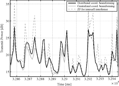
An example of the time evolution of the sum power in a scenario depicted in Figure 6.8 is plotted in Figure C.2, where the behavior of the distributed, centralized (ideal) and ZF beamforming cases is compared in a time-correlated fading scenario with 10 dB SINR constraints. The example demonstrates that the distributed algorithm performs nearly as well as the centralized solution even at relatively high velocities, especially with low SINR targets. In this particular example, two BSs exchange at each reporting instant four real-valued interference terms. The normalized velocity is set at ![]() , where
, where ![]() is the Doppler shift and
is the Doppler shift and ![]() is the signaling period for the exchange of
is the signaling period for the exchange of ![]() between BSs. For example,
between BSs. For example, ![]() ms with 2 GHz center frequency corresponds to the velocity of 27 km/h.
ms with 2 GHz center frequency corresponds to the velocity of 27 km/h.
Figure C.2 Time evolution of the distributed algorithm with 10 dB SINR target, ![]() (Tölli et al. 2011). Reproduced by permission of © 2011 IEEE
(Tölli et al. 2011). Reproduced by permission of © 2011 IEEE
C.2.2 Coordinated Scheduling via Worst Companion Reporting
The performance of the worst companion scheme with cyclically prioritized scheduling has been evaluated with a 3GPP-compliant simulator and the system parameters are summarized in Table C.1.
Table C.1 Simulation details for worst companion method.
| Simulator details | |
| Channel Model | 3GPP SCME 3D |
| Intersite distance | 500 m |
| TX Antennas | 4, vertical polarized with λ/2 antenna distance |
| TX Codebook | DFT-based with tapering |
| RX Antennas | 2 |
| Number of cells | 57 |
| Number of UEs per cell | 15 |
| Scheduler | α-PF |
| α values | 0.5, 0.6, 0.8, 1.0, 1.3, 2.0, 3.0 |
| Transmission rank | 1 |
| Cooperation set dimension | 0–6 |
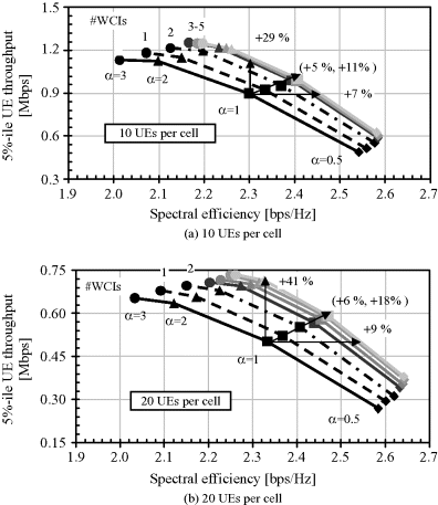
In Figure C.3, the performance of the worst companion reporting algorithm is studied, with different number of UEs. We note that both the cell edge and the cell average gain grow with the UE number. For example for 10 (see C.3(a)) and 20 (see C.3(b)) UEs the gain at the cell edge is respectively 29% and 41%. This is due to the combined effect of multiuser diversity and the fact that with a higher number of UEs the performance at the edge gets lower, so worst companion reporting has a higher impact.
Figure C.3 Cell edge throughput versus spectral efficiency for the worst companion coordinated scheduling method
C.3 Test-Bed: Distributed Realtime Implementation
In modern cellular networks, there is a general tendency to use distributed signal processing. The adaptation to the wireless channel can be much faster if it is performed directly in the serving BS. For Downlink (DL) Coordinated Multipoint transmission or reception (CoMP), the overall delay is reduced in the closed transmitter adaptation loop if the waveforms are generated at the serving BS. Ideas for a distributed implementation of DL CoMP in a limited cluster of coordinated BSs are developed in Jungnickel et al. (2008a), Ng et al. (2008), Papadogiannis et al. (2009), Thiele et al. (2009) and Zirwas et al. (2006, 2009). Base stations are synchronized using the Global Positioning System (GPS). User Equipment estimates the multicell CSI in the Downlink using the Release 8 (Rel-8) Cognitive Radio System (CRS) but estimation is now limited to the BSs in the cluster. User Equipment deliver CSI feedback to its serving BS. Next, BSs in the cluster exchange the CSI as well as scheduled data over a low-latency signaling network. Weights for the joint beamforming are computed redundantly at each BS. The relevant set of weights is applied to the data signals and, in this way, the transmitted waveforms can be computed locally; the desired signals sum up constructively while the mutual interference inside the cluster is canceled.
For local computation of the waveforms, scheduled data and the CSI are needed. Data instead of IQ samples transfer is a light burden for the backhaul. For distributed DL CoMP, latency is more related to the ongoing aging process of the CSI while it is exchanged over the backhaul. A few milliseconds may be tolerated for slowly moving UEs.
Distributed Synchronization
A first requirement of DL CoMP is that the physical layer and radio front ends are tightly synchronized. A precise reference clock is available everywhere where the Line of Sight (LoS) to the sky is free when using an advanced GPS receiver. All necessary clock signals locally at each BS are generated so that the entire radio network is fully synchronized (Jungnickel et al. 2008b). Clock signals comprise frame and sampling clock, the Common Public Radio Interface (CPRI) clock used between base band and Radio Frequency (RF) as well as IF and low phase-noise RF carrier frequencies.
Cell-Specific Pilots
Once in each 10 ms radio frame, the BSs provide cell-specific pilots denoted as CRS from which the UEs can estimate the multicell DL channel. A comb structure in the frequency domain is used where the comb of active subcarriers is shifted to identify the cell. Specific shifts are reused in the network similar to the well-known frequency reuse, so that the overhead due to the introduction of CRS remains limited.
CSI Feedback
Safe transmission using conservative modulation and coding schemes is mandatory for the CSI feedback. Quadrature Phase Shift Keying (QPSK) modulation and code rate 1/2 in 10 MHz bandwidth are used thus splitting the 20 MHz uplink band between the cells. For each pilot in the comb, the CSI for the entire 2 × 4 channel matrix is fed back. While using the full 20 MHz bandwidth for CoMP, one out of four CSI over Ethernet packets contains the feedback for 5 MHz bandwidth. The Ethernet packets are delivered as regular uplink traffic to the BS. Feedback of the uncompressed complex-valued CSI for the 2 × 4 MIMO DL channel to both BSs requires (4 Tx) × (2 Rx) × (144 pilots) × (2 × 16 bit) / 10 ms = 3.68 Mbps, which results in 4.6 Mbps including overhead for higher layers. Time stamps derived from the GPS are introduced in order to ensure that the multicell channel matrix is built from consistent CSI packets at the precoder in each BS.
Synchronous Data Exchange
A technical requirement for distributing the coherent precoding operation in the network is that the data flows are strictly synchronized at the inputs of the local precoders in Figure 6.11 for all BS cooperating in the cluster. The scheduled data after the Medium Access Control (MAC) layer processing have been copied and forwarded the copy over the X2 interface to the other BSs in the CoMP cluster. The maximum load of 300 Mbps has been realized on X2 by exchange of six encoded bits per symbol, while still ignoring the actual MCS used. Load-aware compression of the scheduled data would be implemented in a real network to lower this rate. In this way, the load on X2 becomes highly dynamic and it depends on the traffic in the other cell.
Backhaul Network
Note that the distributed CoMP architecture depicted in Figure 6.11 where both data and CSI are exchanged, turned out as an essential enabler for CoMP trials in the field where distributed UE and BS locations are considered. Only the feedback of the served UE is decoded at the serving BS and then the BSs exchange the CSI. In this way, the CSI feedback is more robust since it is transmitted over the uplink for which power control and timing advance are optimized.
However, complex data flows in the network behind CoMP need to be organized: these are the application-related data for each UE, the CSI feedback and the exchange of scheduled data between the BSs. Therefore all flows needed for distributed DL CoMP are consequently organized using standard Ethernet protocols. This enables the use of widely available low-cost equipment based on the IEEE 802.3 standard. As a general approach, an existing standard extension, namely Virtual Local Area Networks (VLANs) described in IEEE 802.1q (IEEE 2006) is taken into consideration to organize the flows. VLAN-enabled switches are used to multiplex and demultiplex the different types of traffic. Virtual Local Area Networks are based on a label, denoted as tag, based on which a given packet is switched selectively from one input port to one or more output ports in the Ethernet switch. The use of VLANs has a negligible impact on the overall precoder delay. The delays introduced by the network are related to the maximum packet length of 12 μs for 1 Gbps Ethernet, and the propagation times over for example, 5 km optical fiber which takes 25 μs. These delays are negligible compared to the other delays present in the joint transmission loop due to the transmission of the feedback over a bandwidth-limited channel and the computation of the precoding matrices.
The use of VLANs can be extended to support the hybrid clustering approach mentioned in subsection 6.1.2. Potential clusters can be preconfigured by the mobility management using predefined packet routing tables in each VLAN switch. Once a given cluster is formed, UE is informed about the tag to be used over the PDCCH. It broadcasts the CSI over the uplink into the preconfigured subnet identified by the tag. The serving eNodeB (eNB) uses a second tag for broadcasting the data to the other eNBs in the cluster. In this way, data and CSI packets find their own way through the network based on the tags and as much overhead as needed only is created in the backhaul network.
Local Precoder
The local precoder enables manifold multicell transmission schemes. It is realized in the transmitter signal processing pipeline by using a linear matrix-vector multiplication unit originally described in Jungnickel et al. (2005). Selectively for each subcarrier, the incoming IQ signal constellations of data streams from all BSs in a CoMP transmission are multiplied with a weight matrix before the signals are passed into the IFFT at each antenna.
There is an algorithmic part executed in a companion DSP for setting the weights. For DL CoMP, this algorithm assembles at first the CSI received over the feedback link from the UE in the own cell, or over X2 from other UEs in other cells. The resulting channel matrix includes all BSs and all UEs handled in the same cluster. Next the channel is interpolated in the frequency domain. Finally, the Zero Forcing precoding matrix is determined on each subcarrier.
Precoder Algorithms
Three different precoding algorithms have been used, one for interference-limited transmission where the combined precoder matrix in both cells is diagonal. Second, the inverse of the multicell multiuser channel was considered. Third, the other cells have been switched off in order to measure the isolated cell capacity as a reference.
Precoded Pilots
The precoding matrix P depends on the CSI feedback in other cells. It cannot be foreseen by a UE in a given cell how such external feedback in other cells influences the interference situation after CoMP has been applied from the network side. Consequently, a second set of pilots is needed, denoted as DM-Reference Signal (RS) in the Long Term Evolution (LTE)-Advanced standardization. The DMRS enable the UE to estimate the effective, that is, the precoded channel HP. The DM-RS identify the streams provided to the UEs in each cell.
For the DM-RS the pilots used for single-cell transmission are fed through the precoder. The two antennas in the first cell and the two antennas in the second cell are handled as a larger four-antenna array. Note that the single-cell pilot concept used in one cell can be easily extended to cover many cells by introducing a so-called virtual pilot sequences (Thiele et al. 2008). In this way, the additional overhead required for the DM-RS in case of multicell operation can be limited, at the cost of reduced mobility.


