19
Natural Gas to Acetylene (GTA)/Ethylene (GTE)/Liquid Fuels (GTL) The Synfuels International, Inc. Process
Kenneth R. Hall1, Joel G. Cantrell1, and Ben R. Weber, Jr2
1Bryan Research & Engineering, LLC, Texas, USA
2Synfuels International, INC, Parkland Hall, Texas, USA
Chapter Menu
- 19.1 Introduction
- 19.2 Additive and Subtractive Processes
- 19.3 The Synfuels Process
- 19.4 Pilot Plant
- 19.5 Location, Location, Location
- 19.6 Biofuels
- 19.7 Conclusion
19.1 Introduction
Ever since the discovery of producible fields of petroleum, humankind has used its properties as a fuel and a feedstock to advance its needs and desires. A historical description of the advance of petroleum and its products is beyond the scope of this chapter, but suffice it to say that life today would be vastly different, and doubtless more primitive, without petroleum (natural gas and oil).
Chemical engineering and chemistry have played a vital role in advancing use of petroleum over the past century. Among the early advances pertinent to the story in this chapter, is the development of the Fischer‐Tropsch process. Originally it was a means for Germany to turn its ample coal supplies into liquid fuels for its war machine in World War I. Even today, it remains a useful process to convert natural gas into liquid fuels. However, it produces many undesired products that require extensive recycling. In addition, it is an extremely expensive process because it requires processing vast amounts of feedstock to improve economics. A normal plant might process on the order of a billion standard cubic feet per day (BSCFD) of natural gas and cost $10–20 billion. That said several plants exist in the world, notably two massive plants at the Ras Laffan industrial complex in Qatar.
In the years since World War I, the petrochemical industry has grown enormously and has greatly enhanced the quality of life for mankind. World War II provided another major impetus to its growth, which included obtaining data and theories to propel the industry into the gigantic operation it is today.
Along the way, some interesting things happened. Natural gas was considered a nuisance in production unless a ready market was available very close to the production site. As a result, producers usually flared the gas to be rid of it. Yet, natural gas was also a valuable fuel without the distribution problem. Furthermore, it became a vital feedstock for major chemical industries. Then came the idea that “peak oil” had passed, and natural gas could help get the world through that “crisis” if only processes existed to convert it into liquid fuels. Enter cryogenic processing to liquefy natural gas, which could relieve the load on liquid fuels to provide for home heating. Then came the idea to use the Fischer‐Tropsch process to convert natural gas into liquid fuels. This was and is a viable, although expensive, option. Another option would have been to provide a means to “activate” methane that would allow easy transformation into liquid fuels (this concept fizzled for technical reasons).
Over the past few years, it has become obvious that “peak oil” has not passed after all. In fact, it may never have existed. Given modern production technology, IHS Markit estimates that the Permian Basin by itself contains ∼75 billion barrels of petroleum. We have passed from speaking of “peak oil” to dreaming of “infinite oil” in less than a decade. So why do we need natural gas under these circumstances?
Well, as a fuel it burns much cleaner than oil products. Also, converting it into a liquid greatly reduces transportation costs, thereby providing a greater supply from remote production facilities assuming a low‐cost option exists for liquefaction.
In 1996, some professors at Texas A&M University sought a way to destroy toxic wastes using microwaves. This idea was short‐lived because of costs. However, it gave rise to a new way to convert natural gas into liquid products (or to activate methane). This became known as the Synfuels process (named for the company that licensed the technology). The rest of this chapter details the Synfuels process, and demonstrates some of its advantages.
19.2 Additive and Subtractive Processes
Recently, additive technology has demonstrated many advantages compared to subtractive technology. Subtractive technologies have been the normal means to produce products. If a sculptor wants a statue, he carves away the marble that is not the statue. If a refiner wants to produce gasoline from oil, it devises a process that separates the gasoline molecules from all the other molecules in the oil. “Heavy” oils, such as those from tar sands, can have a large fraction of components heavier than those in diesel fuel. To the extent possible, it is necessary to remove these compounds and to devise uses for them other than normal fuels. The Fischer‐Tropsch process produces a product distribution with approximately 50% of the compounds heavier than diesel fuel even when using natural gas as the feedstock. Recovering these molecules in a more useful form is a major expense. However, another undesirable characteristic is that is it impossible to remove all of these compounds, and some long‐chain molecules remain in the products.
However, recently another manufacturing process has begun to emerge. In general, it is additive technology (commonly referred to as 3‐D printing). Now the sculptor could simply write a computer code and “print” the statue from treated marble powder. Likewise, the refiner could construct its gasoline from small molecules, and stop when it reaches the desired properties. So what is the advantage of “printing” a liquid fuel? Well, think about jet fuel. Petroleum‐derived jet fuel still retains some long‐chain molecules that were present in the original oil. These molecules greatly influence the freezing point of the jet fuel, making it freeze at temperatures such as those encountered at high altitudes. Why go to such altitudes? To achieve more efficient use of fuel commercially, or to achieve a tactical advantage militarily. The Synfuels process is an additive technology to produce jet fuel from small molecules that remains free of the long‐chain molecules that provide undesirable properties. For example, if jet fuel is the desired product, the product would have essentially no molecules longer than about C18.
19.3 The Synfuels Process
The concept behind the Synfuels process is to use molecules available from natural gas conversion to build liquid fuel molecules. If this sounds like methane activation, it is (in a practical process that works). The feed gas should be sweet natural gas (passed through an amine unit if necessary) with minimal LPG, e.g., cut at butane.
The trick is to subject methane to temperatures in the range of 4,000 °F and convert it into acetylene. The reaction in its basic form is
These reactions require only heat to occur, but the Synfuels reactor does have a proprietary design to utilize the heat efficiently. The first three reactions (methane to ethane to acetylene) occur very fast, on the order of microseconds. However, the final reaction (acetylene to carbon) is relatively “slow” on the order of 0.5 millisecond. In addition, although acetylene is a very reactive molecule, unlike most hydrocarbons it is stable at these temperatures. Thus, with careful attention to residence time (<1 ms), it is possible to design a reactor that produces acetylene and hydrogen with very little carbon or coke formation. In effect, this is a natural gas to acetylene process at this stage.
However, the equation above shows that hydrogen forms in each step. It is therefore possible to recombine the hydrogen with acetylene to make ethylene for further processing. In other words, we now have a natural gas to ethylene process. Now all ethylene chemistry becomes available, but more germane to this discussion is the ability to convert ethylene into liquid fuels affording us a natural gas to liquid fuels process.
Figure 19.1 presents one possible arrangement for the Synfuels process. The process starts by importing sweet natural gas (if only sour gas is available, an amine unit would be necessary to remove the hydrogen sulfide and carbon dioxide) and commercial‐grade oxygen. The oxygen goes directly to the burner/cracker/quench unit, while the natural gas first mixes with recycle gas coming from the product separation step and then proceeds to the burner/cracker/quench unit. Removing any LPG fraction of the natural gas is not necessary, but it would reduce the cost of the process somewhat while recovering the LPG fractions for direct sale. The burner/cracker/quench unit operates at approximately 4,000 °F (2 200 °C), which is sufficient to crack 50–65% of the methane and essentially 100% of all other hydrocarbons in the feed. The unreacted methane composes a large fraction of the recycle gas that mixes with the inlet natural gas stream. Introducing steam into the burner/cracker/quench unit greatly reduces coke formation in the unit to less than 1% of the inlet carbon. The exit stream from this unit contains acetylene, hydrogen, unconverted methane, carbon oxides, and nitrogen/nitrogen oxides. Commercial absorbents are readily available to separate the acetylene from this gas mixture.
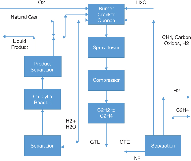
Possible arrangement for gas to acetylene/ethylene/liquids process.
The spray tower washes the exit stream from the burner/cracker/quench unit to remove carbon granules/particles and any green oil produced in the converter. Should acetylene be the desired product, the stream would proceed to a unit to purify the acetylene. Should ethylene or liquids be the desired product, this unit then cools the stream to ambient temperature before compressing it from about 100 psia to 400 psia (7 to 27 bar) before it enters the reactor to hydrogenate the acetylene to ethylene using hydrogen already in the stream produced in the burner/cracker/quench unit.
Normally, hydrogenation of acetylene into ethylene is a gas‐phase reaction. However, it is possible to use a proprietary Synfuels process to perform the hydrogenation in a liquid phase. Liquid‐phase hydrogenation has safety advantages over the gas‐phase hydrogenation. Obviously, the reactor would be smaller in a liquid‐phase process, which reduces the cost. However, the liquid‐phase process also produces a better product for continued processing.
At this point, the operator can elect to produce ethylene, liquid fuels, or both. Producing both probably would be an unlikely choice from an economic viewpoint, but the possibility exists if it does make sense. It is noteworthy that production of acetylene or ethylene in this process does not require recycle of the product.
Assuming ethylene is the desired product, the stream from the hydrogenation unit would pass to a cryogenic separation, which would purify the ethylene and could split out the hydrogen should that be desirable. The remainder of the stream (composed of unreacted methane, carbon oxides, possibly hydrogen) would recycle to the burner/cracker/quench unit primarily as fuel. Removal of nitrogen and nitrogen oxides would be beneficial in this unit before recycling to the burner/cracker/quench unit. This choice presumes the proximity of chemical‐processing plants that utilize ethylene and hydrogen. Transporting either of these products long distances to a user would not be an economical enterprise in almost any circumstances, even though they are usually more profitable than liquid fuels. Normally, it would be less expensive to transport the natural gas directly to the proximity of the end user and convert it into ethylene and hydrogen there.
Assuming liquid fuel is the desired product, the stream from the hydrogenation unit would pass to a catalytic reactor that would oligomerize the ethylene (and possibly a small amount of the hydrogen) into a liquid stream, which could be primarily gasoline, jet fuel, or diesel fuel, and a recycle stream composed of light hydrocarbons (C5 and lighter) that passes to the burner/cracker/quench unit.
Operation of the oligomerization unit at low pressure (near atmospheric) produces gasoline. This product (after stabilization) is a 95‐octane, C8‐average fuel that contains about 30% aromatics (but very little benzene), 40% iso‐alkanes, and 30% cyclo‐alkanes. An important feature of the Synfuels gasoline is its comparison in its product distribution to that of a Fischer‐Tropsch process. Figure 19.2 provides the comparison. The obvious advantage of the Synfuels product is the tight distribution about a carbon number of 8. No long‐chain liquids or waxes form. The Fischer‐Tropsch products do form a large fraction of very long‐chain molecules, which require recycling unless a market exists for these molecules. Regardless, the recycle adds significantly to the cost of operation.
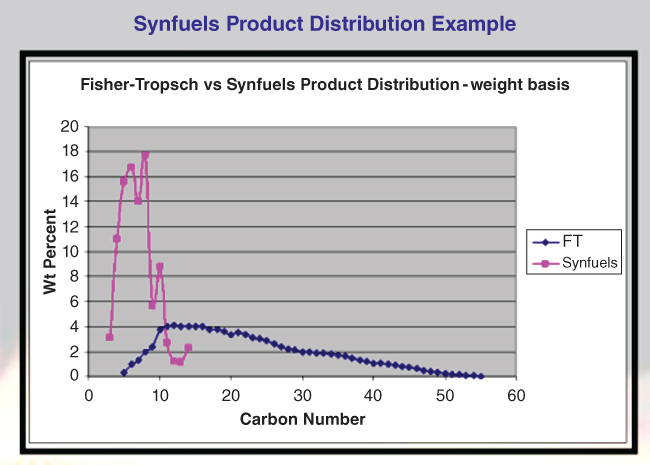
Figure 19.2 Comparison of Synfuels gasoline production to that of Fischer‐Tropsch.
It is possible to operate the Synfuels reactor in a manner that would reduce the aromatic content while the iso‐ and cyclo‐alkanes would remain in essentially the same ratio. This option might be preferable for gasoline production, but if jet fuel is the desired product, the aromatics are essential components. An interesting option is that the Synfuels plant can operate to produce various fractions of aromatics (10–45 wt%), which enables the producer to fine‐tune the jet fuel. Jet fuel production requires higher‐pressure operation than gasoline production. Operation at still higher pressures can produce diesel fuel.
Another option would be to separate the aromatic compounds as a product. They would be liquid and easily transportable. They would have a high value as feed stock for the chemical industry. Then the alkanes could provide an alkylation stock for the gasoline industry. One other option would be to use a demethanizer on the feed stream. This would allow the process to be more efficient in converting methane into the products described. Then depending upon location, the C2+ fraction could feed a smaller, more efficient unit to convert these compounds into acetylene, ethylene or liquid fuels.
19.4 Pilot Plant
Some preliminary scoping of catalysts for the hydrogenation and oligomerization, performed at bench scale, provided high enough yields (∼15%) to encourage advancing the project to larger scale. Commercial development would require yields approaching 40–50%. However, the pyrolysis performance depended strongly upon geometry and scale. Development, testing, and optimization of the pyrolysis reactor required pilot tests. Synfuels constructed a 50 MSCFD pilot plant in Robertson County, Texas, for this purpose. Over the course of four years, a design emerged that could endure the extreme conditions required for methane activation, was reasonably inexpensive to produce, and provided the instrumentation and operating flexibility for remote and varied application. In addition, the reactor utilized an internal flame in a hydrocarbon‐safe environment, which provided safety and robustness of the operation.
The original design for the hydrogenation reactor was a gas‐phase, fixed‐bed reactor similar to acetylene hydrogenation found in ethylene production processes. However, the non‐isothermal pilot reactor revealed an acetylene concentration high enough that the reaction heat management was unreliable and prohibitively expensive to control with recycle gas dilution. In addition, the propensity of the acetylene to self‐react created residues that caused rapid deactivation of the catalyst. Safe management for the heat of reaction and keeping the catalyst clean required a liquid solvent in the process instead of recycle dilution. The mass of the solvent helped limit the temperature rise of the reaction materials and maintain selectivity of the reaction. Additionally, the solvent was selective for acetylene, which allowed removal of acetylene from the bulk pyrolysis gas. This reduced the volume of gas processed, especially when ethylene was the target product. Because the solvent was selective for acetylene, it also favored production of polyacetylenes as byproducts. The solvent swept these compounds from the reactor to a slipstream cleanup process.
The oligomerization unit, when piloted, performed much the same as it had in the lab. The yield, quality, and catalyst deactivation were acceptable.
While the pyrolysis reactor was a success at the pilot scale, it was a design that would be sensitive to geometric scale‐up in terms of operation and efficiency. Because energy efficiency is proportional to surface area, as the reactor scales up, fuel and oxygen consumption would decrease. To demonstrate this increase in efficiency, the pyrolysis reactor required scale‐up from 50 MSCFD to 1 MMSCFD. The scale was definitely worthwhile. While providing the same burner stability and thermal efficiency as expected, the cracking reaction section revealed that the pyrolysis time estimated from the pilot cracker was insufficient for the mid‐size unit. In addition, while the location of the quench was understood in the pilot reactor, the exact quenching temperature profile was not. The mid‐size reactor required more reaction time. After increasing the length and optimizing the conditions, the mid‐size reactor demonstrated expected performance with improved fuel efficiency. In addition, mid‐scale testing allowed refinement of the ignition and quenching systems at realistic reactor volumes.
The 50 MSCFD reactor converted about 33% of carbon in lean gas per pass. The 1 MMSCFD reactor converted about 40% of the carbon in lean gas and about 46% of the carbon in rich gas (associated gas). The pilot plant demonstrated convincingly that the Synfuels process worked.
The Synfuels technology has several advantages over traditional processes from design, construction, and products vantage points. Some of the more visible are:
- Standard materials of construction: Most of the Synfuels equipment is carbon steel. The pyrolysis reactor is a common grade of stainless steel, and the hydrogenation reactor has an internal lining made of stainless steel.
- Static catalyst beds: While fluidized catalyst beds can be advantageous, they are more expensive and more difficult to design, build, and operate than fixed‐bed units. The Synfuels reactor is a multisection fixed‐bed unit with minimal catalyst attrition, and far less chance of downstream damage caused by catalyst infiltration.
- Very low recycle: Most GTL processes (especially Fischer‐Tropsch) have low per pass conversions that require significant recycle to achieve the required conversions. The Synfuels process has very little recycle and yields about 3% light products. The process has lower capital and operating costs, smaller equipment, and less environmental impact than other GTX processes (a Fischer‐Tropsch process would be about 3.6x the cost of a Synfuels process per barrel of product).
- Low pressure operation: The maximum operating pressure in a Synfuels plant is about 300 psig (compared to 800–1200 psig for Fischer‐Tropsch plants). This reduces cost while improving safety.
- Safe hydrogenation: The liquid‐phase hydrogenation reactor has a temperature rise of about 60 °F compared to 400–800 °F rises in a gas‐phase hydrogenation.
- Minimal by‐products: The Synfuels process produces only CO2 and water as by‐products.
- Scalability: Tests of the Synfuels reactors indicate that they can scale up to any full‐size operation.
| Pilot Plant | Mid‐Scale | Commercial | |
| Design pyrolysis gas flowrate1 MSCFD | 50 | 1000 | 50000 |
| Actual pyrolysis gas flowrate1 MSCFD | 24.7 | 454.8 | 50000 |
| Short‐term pyrolysis yield wt% carbon | 34.0 | 41.2 | 45.3 |
| Long‐term pyrolysis yield wt% carbon | N/A | 39.9 | 44.02 |
| Scale‐up ratio wrt pilot plant | 1 | 18.5 | 202.8 |
| Short‐term conversion increase wt% carbon | – | 7.2 | 4.1 |
| Heat loss % of nominal burner duty | 42.7 | 17.7 | 8.4 |
Notes: 1. Pyrolysis gas carbon number = 1.0.
2. Long‐term commercial yield obtained from de‐rating short‐term yield by 1.3%.
19.5 Location, Location, Location
Fischer‐Tropsch plants are very large and very expensive because the process is relatively dirty and complex. As a result, location of the plants must be near the source of feedstock, coal originally and natural gas recently (the process dates back to World War I when Germany had abundant coal but little oil to fuel its war effort). As a result, without reasonably proximate feedstock sources (think Qatar), transportation costs can render the process uneconomical especially for natural gas. Locating a Fischer‐Tropsch plant in remote or cold locations is a prohibitively expensive project. The same is true for many natural gas fields.
The Synfuels process is much smaller and less expensive than Fischer‐Tropsch. It is possible to construct an economical Synfuels plant at about 10 million SCFD. It also is possible to construct these plants at sizes required for Fischer‐Tropsch plants (BSCFD) – the difference is they would be approximately one‐third the size and cost. Thus, it is conceivable to construct Synfuels plants in remote locations with economical gas flows. It is even possible to construct one on a large tanker, which could move when the source field played out. Even smaller plants might have military applications in which mobility needs might offset additional expense.
19.6 Biofuels
Interestingly, the Synfuels process is amenable to use in biofuel production. This process does not use corn nor any other food crop (food to fuel) to make ethanol for mixing with gasoline. Byogy Renewables, a company separate from Synfuels, has developed a process, based upon the Synfuels process, to convert biomass into ethanol and ethanol into fuels.
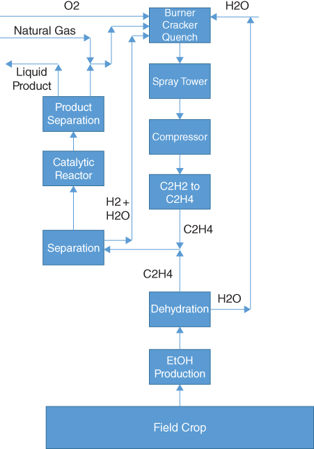
Figure 19.3 Introduction of Byogy Renewables process into Synfuels process.
Consider Figure 19.2, which is very similar to Figure 19.1. The additional reactions are:
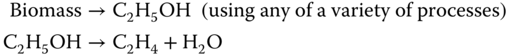
Both process produce ethylene from a feedstock: natural gas in the case of Synfuels and biomass in the case of Byogy Renewables. Clearly, the ethylene streams can mix and proceed to common processing. However, the location issue rears its head again. What if no biomass source is near the Synfuels process? Well, ethanol is relatively inexpensive to transport as one option. Figure 19.3 presents another option.
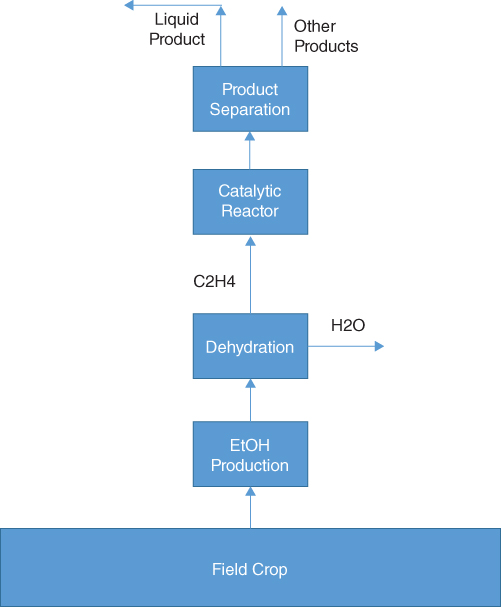
Figure 19.4Figure 19.4Byogy Renewables process utilizing only Synfuels conversion technology.
This option could have a location near the biomass source. In addition, the greatly simplified Synfuels process would cost significantly less than the one to convert natural gas into fuels. Conversely should a Synfuels plant location abut a biomass source, the addition of a Byogy Renewables unit would add little additional expense.
Pilot testing of the Byogy process primarily targeted achieving volumes of product that would meet customer requirements. Bench scale tests verified the catalyst sequence to generate jet fuel from ethanol (which is actually superior to petroleum –derived jet fuel). The main challenge was to move from an isothermal to a non‐isothermal reactor environment, particularly for a highly exothermic reaction in which yield and selectivity were sensitive to temperature. The pilot reactors represented the expected length and diameter of commercial reactor tubes. The reactors proved to be challenging to control, but ultimately stable and effective. The product quality exceeded the customer specification.
It is important to note that Byogy Renewables has identified a nonfood biomass source that provides much more ethanol per mass than corn. The synergistic combination of these technologies offers an intriguing source for transportation fuels derived from nonconventional sources.
19.7 Conclusion
Synfuels International has conceived and tested through pilot scale, and partially through mid‐range, a unique process to convert natural gas to acetylene, ethylene, or liquid fuels including gasoline, jet fuel, and diesel fuel. The process has the advantage of using additive technology to produce its products, which greatly reduces plant size and cost compared to Fischer‐Tropsch technology. Commercial plants as small as 10 MMSCFD can be practical, but scale‐up to essentially any throughput is feasible. The pilot and mid‐scale testing proved that the products would meet or exceed customer specifications.
An added bonus is that the process can accept non–food‐derived ethanol as the feedstock. In contrast to use as a fuel diluent, the ethanol transforms into ethylene, gasoline, jet fuel, or diesel fuel. The jet fuel is particularly interesting in that it has a freezing point lower than −80 °C. It also is possible to produce the jet fuel with any desired amount of aromatic concentration while maintaining a very low concentration of benzene.
The process is ready for commercialization. It has received in‐depth scrutiny at multiple levels from potential users. None have found any technical flaws.