Programmable logic controllers
2.7.1 Programmable logic controllers
Industrial processes have been traditionally controlled by electromechanical systems (i.e. switches and relays). An electromechanical control system controls the output states according to the input states. The logic behind the switching and the resultant actions depend upon way the switches and relays are wired together. The overall function in these systems is not so easily changed and the systems are not easily maintained.
In the late 1960s, digital controllers were introduced to allow some degree of programming to control the sequence of operations required in an industrial process. A programmable logic controller (PLC) examines its input states and turns off or on its outputs according to a pre-loaded program that can be easily altered to suit changed circumstances. Advances in technology have resulted in programmable controllers that can communicate with each other, as well as receive and transmit control data to remote locations. Present day systems feature functional block diagrams and structured programming in a standardised way.
PLC devices have standard input and output interfaces. Standard input interfaces allow direct connection to process transducers. Standard output interfaces allow direct connection to relays or circuits that energise process actuators.
PLC devices operate under program control. A program consists of a series of statements or logic instructions called a list. The control unit scans the inputs and performs logical operations according to the loaded program and then switches the outputs accordingly. The inputs are then scanned again and the cycle repeats. The result is an industrial process.
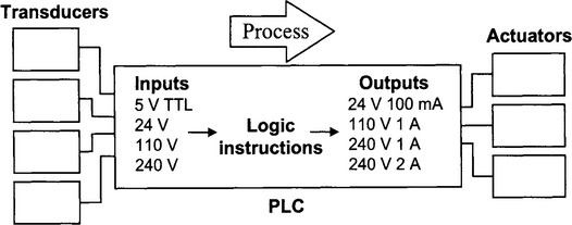
A PLC itself consists of the control unit (or CPU) as well as connections for input and outputs, RAM memory (≈10 Kb) and a power supply. Inputs are opto-coupled to the input circuits in the PLC to protect the PLC from noise.
2.7.2 Timing
A PLC program consists of a series of instructions that represent logical operations performed on the inputs. The state of the outputs is set or cleared in accordance with the logical result of the program instructions.
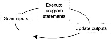
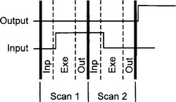
The states of all the inputs are copied into RAM before the program instructions are executed. Instructions are then processed in sequence. The resulting output states are stored in RAM. When the program execution is completed, the stored output states are transferred to the output terminals of the PLC.
Since it takes a finite time for the PLC to read the inputs (input response time), process the instructions (execution time) and set the outputs (output response time), changes to the inputs can only be registered if they last longer than the scan time (input response time + execution time + output response time). If the input changes more rapidly than this, then the PLC may not detect the change and the required output may not be set. This is called a phasing error.
When an input changes state, the resulting change in the output will take place, in the worst case, two scan times (less one input response time) later.
PLC scan times are usually quoted in terms of the length of time to execute a 1024-byte program and depend upon the clock rate of the controller. Scan times are usually in the order of 5 to 10 msec.
2.7.3 Functional components
The PLC inputs consist of input relays or contacts which may be physically real devices or simulated as labelled contacts in the program. The outputs are called coils representing the coil of a relay. The outputs can take the form of transistor switches, triacs or relays. As well as inputs and output devices, the control unit also typically contains latches, counters, timers and registers for data storage. Some PLC devices also have analog I/O capability.
| Latch | When set to true, the output of the latch will stay on until the latch is reset. |
| Counter | Counts pulses at its input and sets the timer output to true when a preset number of counts have been registered. True at the reset input resets the accumulated count to zero. |
| Timer | Output of the timer turns on or is true a preset number of seconds after the input is true. When the input is set to false, the timer is reset and the output is set to false. While the timer is counting down, the PLC continues to scan and execute its instructions. Input and output errors can occur with timers since the input to the timer may not be registered until it is scanned. Further, the output device may not be energised until the PLC has completed executing the program. |
| Registers | Used for storing data or the results of logical operations as bits (true 1 or false 0). Registers are similar to internal contacts. The contents of registers may be shifted left or right. Data bits can be moved into and out of registers using a MOV instruction. |
A PLC can generally communicate with external devices using RS232 serial communications. The PLC may be fitted with an RS232 serial port for this purpose. Data may be sent to or received from the PLC. The data can be stored in the PLC data memory.
The actual logic program run by the PLC is usually entered through a keypad or downloaded from a microcomputer. Before a program is executed, various levels of verification are performed to ensure that the program was transferred successfully into the CPU of the PLC. Various systems are employed to protect processes and plant in the event of a power loss. PLC systems are designed to be robust and operate unattended in an industrial environment.
2.7.4 Programming
PLCs act upon list code instructions. To facilitate the creation of a list code, ladder logic diagrams are used to simulate the existence and actions of input and output devices. A ladder diagram consists of two vertical rails inside which are placed symbols for contacts, relays, functions, and logical operations on rungs. Logic flow (or current flow) is from left to right and top to bottom on the diagram. An output on a rung is energised if there is a continuous path of true logic leading back to the left (or positive) rail of the ladder (logic continuity).
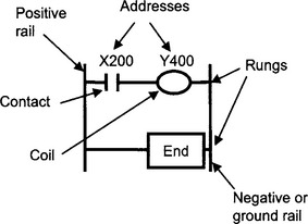
Each rung must contain one or more inputs and one or more outputs. The first object on a rung must be an input and the last object on a rung should be an output, a counter, timer or an internal relay. The last rung in a ladder diagram is an END instruction.
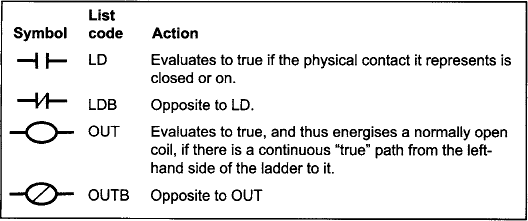
The PLC scans the ladder diagram from top to bottom and left to right. In a load instruction (LD) the physical state of a scanned input is determined and the symbol in the ladder diagram evaluates to true if the physical device is closed or on. The symbol may also be used for internal utility relays or switches that do not physically exist.
2.7.5 Ladder logic diagrams
Ladder diagrams can become quite complex. PLC systems generally have the ability to perform math functions on data, apply Boolean operators, and store data in registers or memory locations.
Consider these simple examples:
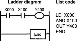
An output is only energised when there is a continuous true path from the left-hand side to the right-hand side of the ladder.
Output Y400 is energised (true) as long as inputs X000 AND X100 are both closed (true).
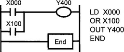
Output Y400 is energised (true) as long as input X000 is closed OR X100 is closed (true).
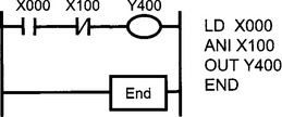
Output Y400 is energised (true) as long as input X000 is closed AND X100 is open (false).
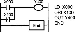
Output Y400 is energised (true) as long as input X000 is closed OR X100 is open (false).
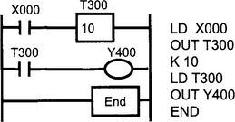
When X000 turns on (true) then timer T300 begins counting down. After 10 seconds, switch contacts for the timer T300 are closed (true) and output Y400 is energised (true).
The example below shows a timer circuit whose output device turns on and remains on for the time period when an input pulse appears at the input. This circuit uses an internal relay. Internal relays are coils and contacts that are simulated by the PLC in memory. Like external relays, they consist of an output coil and a set of contacts that can be used as the input to other objects on a ladder rung.
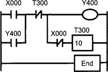
In this example, when the input X000 is true, there is logic continuity through the normally closed timer contacts T300 to the output Y400. This true state is fed back into the input to the normally closed contacts of the timer. Thus, when the input X000 goes false, the output Y400 remains on, it is latched by its own contacts. Now, when X000 goes false, a true signal is sent to the timer to begin the countdown period. During the countdown period, the output device Y400 remains energised by the latched path through the contacts Y400. When the countdown period has expired, the normally closed contacts of T300 become open, thus interrupting the logic continuity to the output Y400 and so Y400 is de-energised. The ladder logic above acts like a pulse extender. A short pulse on the input X000 can be extended into a longer pulse appearing at the contacts of the output Y400.
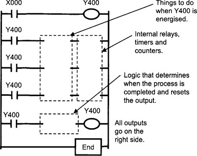
Ladder logic diagrams can easily become unwieldy and difficult to maintain unless a certain methodology is followed to give them structure.
All inputs go on the left side.
2.7.6 PLC specifications
There are numerous PLC systems available. The table below gives typical specifications and features.
2.7.7 Review questions
1. The scanning operation that is the feature of a PLC can be considered to be similar to the multitasking mode of operation of an event-based applications language like Visual Basic. Would you agree?
2. Design a ladder logic diagram that switches on a refrigerator compressor motor when the temperature rises above a preset limit and switches it off when the temperature falls below another preset limit.
3. Design a ladder logic diagram that will control a pedestrian crossing with a set of traffic lights. A press button on each side of the street act as inputs. “Red”, “Amber” and “Green” traffic lights, “Walk” and “Don’t Walk” indicator lights are the outputs. When a pedestrian presses a button momentarily, there is a 60 second delay before the “Green” lights are extinguished and the “Amber” lights are illuminated. “Amber” is illuminated for 10 seconds, then is extinguished, and “Red” is illuminated. There is now a 2 second delay before the “Walk” signs are illuminated. “Walk” is illuminated for 60 seconds after which time it is extinguished and the “Don’t Walk” signs are flashed on and off for 10 seconds. After 10 seconds, “Don’t Walk” is held continuously on. At this time, there is a 2 second delay before the Red lights are extinguished and the Green lights are illuminated. The Green lights are kept illuminated if there is no momentary press of the pedestrian button. If a pedestrian presses a button more than once while the Green ligh then the system only responds to the first press. If a pedestrian presses a button during the “Walk” and flashing “Don’t Walk” parts of the cycle, then these presses are ignored.