Chapter 4
The TLM Method in Matrix Form and the Z Transform
4.1. Introduction
In Chapter 2 we saw the various nodes that can be used in the traditional form of the TLM method. For example, the SCN node formed of 12 transmission lines, to which open circuit and short-circuit stubs, representing permittivities and permeabilities respectively, are added. Matched lines can be added in order to account for lossy media. This approach is effective for a simple medium whose parameters are independent of frequency. Nevertheless, complex media, such as dispersive or anisotropic media, whose parameters are dependent on frequency, require a different process in order to account for this variation. An interesting approach has been presented by Christopoulos [PAU 99], where the propagation of a wave in a vacuum is separated from the wave-matter interaction. The propagation is handled by the traditional TLM method [HOE 92], using 12-input nodes (vacuum), whereas the wave-matter interaction appears in the form of additional electromagnetic field sources. Since the interaction is causal, the Z Transform can be used to treat the problem. The advantage of this application is that convolution products can be avoided in the temporal processing of dispersive media. Moreover, in this case, the algorithm is unconditionally stable. In this chapter we are going to present the matrix formulation of Maxwell’s equations, then the application and implementation of the Z Transform, which will enable the simulation of dispersive media.
4.2. Matrix form of Maxwell’s equations
Maxwell’s equations and the constitutive relations of the matter can be expressed in a matrix form, which is convenient for formulating the problem:
[4.1] 
[4.2] 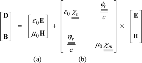
(a) expresses the relation in the vacuum, and (b) the wave-matter interaction.
The currents are given by:
[4.3] 
![]() and
and ![]() are the electrical and magnetic susceptibility tensors, respectively (without dimension);
are the electrical and magnetic susceptibility tensors, respectively (without dimension); ![]() and
and ![]() are the electromagnetic and magnetoelectrical coupling tensors; Jef and Jmf are the free electrical and magnetic currents;
are the electromagnetic and magnetoelectrical coupling tensors; Jef and Jmf are the free electrical and magnetic currents; ![]() and
and ![]() are the electrical and magnetic conductivity tensors and
are the electrical and magnetic conductivity tensors and ![]() and
and ![]() reflect an eventual magnetoelectrical interaction. All of the tensors are (3 × 3).
reflect an eventual magnetoelectrical interaction. All of the tensors are (3 × 3).
The notation “×” in equations [4.2] and [4.3] in the remainder of this chapter expresses convolution in the time domain.
4.3. Cubic mesh normalized Maxwell’s equations
In this section, the mesh of the elementary 3D TLM node cell is such that Δx = Δy = Δz = Δl (Figure 4.1).
Figure 4.1. The elementary cell used

The normalizations are as follows:
[4.4] ![]()
where ![]() is the free space impedance
is the free space impedance
The normalized current sources Jef and Jmf are also obtained:
[4.5] ![]()
which leads to normalization on the electrical and magnetic conductivity:
[4.6] ![]()
The spatial and temporal derivatives are also normalized:
[4.7] 
Δt is the time step and ![]() is the normalized time.
is the normalized time.
By applying these normalizations in 3D TLM, with ![]() the following expression is obtained:
the following expression is obtained:
[4.8] 
The first part of equation [4.8] refers to propagation in a vacuum, and can be solved using the traditional TLM method. The second part deals with wave-matter interaction, which behaves in the same way as the sources.
4.4. The propagation process
The propagation process is directly based on the equivalence between the model deduced from the circuit laws and that computed by Maxwell’s equations. The formulation for 3D TLM is based on the symmetrical condensed node (SCN), which is a node with 12 different polarizations represented by the 12 corresponding voltage pulses Vi = [V1 V2 …. V12] T on its six arms (see Figure 2.3). The six electromagnetic field components (Ex, Ey, Ez, Hx, Hy and Hz) are defined at the center of the cell formed by this node.
The “total field” vector F = [Vx Vy Vz ix iy iz]T is defined by:
[4.9] 
[4.10] 
This total field vector enables the components of the electromagnetic field to be expressed based on the voltage pulses Vi, by taking into account the normalizations defined above.
The propagation process occurs in three essential stages:
– Definition of the external excitation vector at node FR from incident voltage pulses and free excitation sources Ff:
This vector is expressed in simple matrix form,
![]() , where:
, where:
[4.12] 
– Evaluation of the total fields: the left hand side of relation [4.8] with these definitions is written 2 FR − 4 F. The relation between the “total field” vector F and the “excitation” vector FR is obtained by solving the general equation [4.8]. This is performed by using the Z transform. It is expressed by the matrix [t(z)], which represents the matrix of transmission coefficients.
We can then write:
[4.13] ![]()
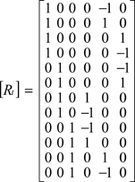
– Computation of reflected pulses: the reflected pulses are obtained by:
[4.14] ![]()

and the matrix [Rt]:
The process is summarized in the following organigram (Figure 4.2):
Figure 4.2. Organigram of the propagation process for the TLM with the Z transform

The role of the [P] matrix in this organigram is to arrange incident voltage pulses V in order to obtain the vector ![]() . It should also be noted that the components of the reflected pulses vector VR are renumbered.
. It should also be noted that the components of the reflected pulses vector VR are renumbered.
4.5. Wave-matter interaction
The term on the right-hand side of equation [4.8] involves convolution products. In order to deal with this problem, the Z transform is used which enables the products of convolution to be passed to simple products. A bilinear transformation is used, of the form:
[4.15] ![]()
If s = j, ω represents the derivative, we obtain:
[4.16] ![]()
where z−1 is the time shift Δt.
Under these conditions, the second part of relation [4.8] can be written based on the Z transform, as follows:
[4.17] 
where:

Relation [4.8], including these transforms, is written:
[4.18] ![]()
or:
[4.19] ![]()
In matrices ![]() and
and ![]() there are some constant elements and others which are dependent on frequency. In order to cause the frequency dependence, we make use of the causality of elements in order to use the shift in time.
there are some constant elements and others which are dependent on frequency. In order to cause the frequency dependence, we make use of the causality of elements in order to use the shift in time.
Thus, the expression z−1 F transfers the value for F at the previous instant. This is written:
[4.20] ![]()
[4.21] ![]()
where ![]() and
and ![]() are frequency independent, which then gives us:
are frequency independent, which then gives us:
[4.22] ![]()
[4.23] ![]()
Following further development of the computations, we arrive at the following expression:
[4.24] ![]()
where:
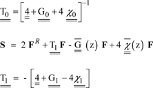
From these last relations, the organigram of the process is established, including all of the permittivity, permeability and conductivity tensors (Figure 4.3).
Figure 4.3. Organigram of the process

In order to model the media under investigation, by knowing the general tensors ![]() and
and ![]() it only remains for expressions [4.20] and [4.21] to be re-used in order to determine the terms
it only remains for expressions [4.20] and [4.21] to be re-used in order to determine the terms ![]() , and
, and ![]() (for example, see section 4.7).
(for example, see section 4.7).
4.6. The normalized parallelepipedic mesh Maxwell’s equations [LOU 04]
A variable step mesh is often used for structures with inhomogeneities, i.e. the application of a thin mesh in high field gradient areas and then a coarse mesh in the rest of the structure.
For the development which follows, the following normalizations are used:
![]()
where Δl is the spatial step used in the process.
Thus, the following normalized values are obtained:

where ![]() is the free space impedance.
is the free space impedance.
Time is also normalized: ![]()
The tensor values ![]() ,
, ![]() and
and ![]() that need to be taken into account in the process of the method are based on the elementary dimensions (u, v, w) of the TLM cell.
that need to be taken into account in the process of the method are based on the elementary dimensions (u, v, w) of the TLM cell.
Maxwell’s equations are solved by considering relation [4.2]:
– First equation: − rot ![]() .
.
[4.25] ![]()
After further development (Appendix A), the final expression for the equation becomes simpler and is written in the following form:
[4.26] ![]()
Using equation [4.2], the curl is expressed in the following form:
[4.27] ![]()
and, in this case, equation [4.8] is written as:
[4.28] ![]()
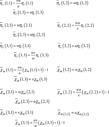
The new tensor parameters are given by (Appendix A):

Once the tensor parameters have been computed, we then have an identical situation to that of the uniform mesh.
4.7. Application example: plasma modeling [MOU 06]
4.7.1. Theoretical model
By way of example, we will discuss the case of non-magnetized plasma. Its permittivity tensor is given by:

where ![]() refers to the relative permittivity of the plasma.
refers to the relative permittivity of the plasma.
The electrical susceptibility tensor of the plasma is expressed in the form:

Within the technical context of the Z transform for the TLM method, the plasma can be handled as a purely dielectric medium. Its conductivity tensor is null and its susceptibility tensor is reduced to:

The representation of the computation process, which enables the plasma to be integrated, occurs through solving the ![]() equation (equation [4.21]), having applied the Z transform to the expression for its susceptibility tensor. Indeed, this solution enables the parameters of the plasma, which must be considered in the algorithm of this Z transform technique for the TLM method, to be determined. This computation is developed in Appendix B. To summarize, the following parameters are obtained:
equation (equation [4.21]), having applied the Z transform to the expression for its susceptibility tensor. Indeed, this solution enables the parameters of the plasma, which must be considered in the algorithm of this Z transform technique for the TLM method, to be determined. This computation is developed in Appendix B. To summarize, the following parameters are obtained:

where:

The solution obtained using the Z transform technique for the TLM method is written in the following form:
![]()

For the plasma, the following is obtained:

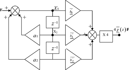
In order to evaluate the term ![]() , we make use of the phase-variable states technique. We obtain:
, we make use of the phase-variable states technique. We obtain:

where:

This computation process is summarized by the organigram in Figure 4.4.
Figure 4.4. Organigram of the computation of a plasma medium
4.7.2. Validation of the TLM simulation
Validation of the propagation simulation concept is performed on a structure using a parallelepipedic resonant metallic cavity (Figure 4.5). Firstly, the resonant modes are determined by simulating an empty cavity, which is thus considered to be a reference cavity. Then, cavities filled with plasma are simulated and their responses compared with that of the reference cavity.
The TLM method has been designed in order to deal with media with permittivity and permeability such that εr≥1 and μr≥1. When this is not the case, the convergence of its algorithm is not guaranteed.
In the plasma example, the condition regarding permittivity is not fulfilled (see [4.29]). In order to compensate for this problem, a dielectric, or static constant can be added to the plasma, which thus presents a constant permittivity εr>1 and which compensates for the value of the permittivity brought into play by the plasma in order to avoid this type of divergence. This value for static permittivity is applied during testing of the reference cavity in order to isolate the response obtained by the plasma effect.
Figure 4.5. Metallic cavity

In order to achieve simulations which enable the plasma to be modeled, cavities with the dimensions 23 × 17 × 60 µm3 have been used. For these cavities, a static permittivity with a value of 2 has been used. At the same time, several plasma types have been tested. Indeed, the plasma is characterized by its plasma angular frequency ωp and the frequency of collisions between particles vp. For the micrometric dimensions chosen, the plasma samples tested are as follows:

This choice for the value vp is justified by the approximation, which is often used in low-pressure plasma studies, enabling the expression for the relative permittivity of the plasma to be simplified. It is expressed in the form:
[4.29] ![]()
The simulation of these cavities is achieved using a network of transmission lines with a base mesh Δl of 1 µm and a time discretization step Δt of 1.667 × 10⁻¹⁵ s. Each simulation uses 200,000 iterations. Excitation is a Dirac signal.
For each cavity, the response obtained is compared with the reference cavity, as well as the expected theoretical values.
For this series of cavities, the resonant modes researched were 101, 102 and 103.
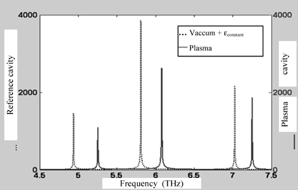
The responses from the filled cavities for plasma #1, #2 and #3 samples are given in Figures 4.6 to 4.8. Each response is compared with the reference cavity corresponding to this series.
Figure 4.6. Resonant frequencies in the filled cavity of a plasma #1 sample, simulated by the TLM method
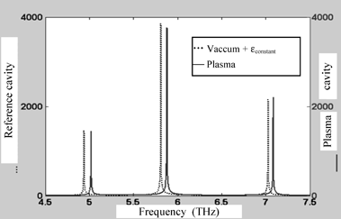
Figure 4.7. Resonant frequencies in the filled cavity of a plasma #2 sample, simulated by the TLM method
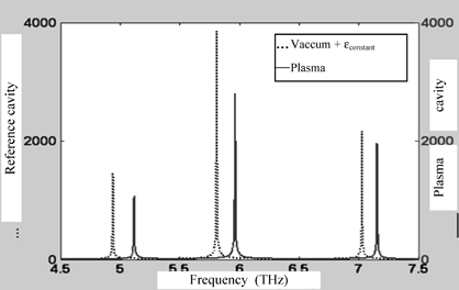
Figure 4.8. Resonant frequencies in the filled cavity of a plasma #3 sample, simulated by the TLM method
The resonant frequencies of each resonant mode of all of the cavities are given by the formula:
[4.30] 
Table 4.1 Comparison of results obtained using the TLM method with theoretical values for a cavity filled with the plasma #1 sample

Table 4.2 Comparison of results obtained using the TLM method with theoretical values for a cavity filled with the plasma #2 sample

Table 4.3 Comparison of results obtained using the TLM method with theoretical values for a cavity filled with the plasma #3 sample

The comparison of resonant frequency values for each cavity, obtained by simulation, compared to those computed using traditional formulae, enable the relative errors resulting from these simulations to be estimated. The value of these errors does not exceed 1%. This low simulation error rate confirms the good modeling of wave propagation for the TLM method and the Z transform.
4.8. Conclusion
The application of the Z transform in the TLM method is extremely useful for two main reasons. On one hand, it enables the rigorous simulation of physical dispersive media (causality property) without the need to deal with problems from convolution, which are always memory hungry. On the other hand, the process is unconditionally stable. It can, of course, be used for non-dispersive media, although, historically, the traditional method is always used.
