
Chapter 11. Implementing a process engine in the ESB
- Using a process engine for stateful flows
- Ensuring a clear separation between an ESB and a process engine
- Implementing a case study with jBPM and Mule
- Implementing a case study with Apache ODE and ServiceMix
In the previous chapters, we’ve discussed different functionalities of open source ESBs including routing, transformation, connectivity, and transactions. These functionalities focus on integrating services and applications with message flows. Most of these message flows are stateless, which means that no state is preserved after the message has been routed through the open source ESB. The stateless characteristic of message flows is also an important aspect for an ESB to be able to scale when needed.
But in some scenarios, you want the state to be preserved during multiple message flow invocations. The time that passes between these message flow invocations can be days or even weeks in some environments, so you need an additional component to implement stateful flows.
In the integration market, these stateful flows are often implemented in process engines. Process engines are designed and implemented to be able to preserve state between message invocations by using transactions and database persistency by default. Within a process engine, stateful flows are often called processes; you can implement these processes with a process-definition language, such as the Web Services Business Process Execution Language (WS-BPEL) OASIS standard.
In this chapter, you implement a case study in which hotel guests book scuba diving trips using WS-BPEL. This example shows the added value of a process engine. Multiple service invocations are required to book a scuba diving trip: a taxi reservation service, a lunch reservation service, and a booking service for the trip at a diving agency. Implementing such a case study with just ESB message flows would lead to a complex, difficult-to-maintain integration solution. By using a process engine, you can implement the service invocations with one process definition that takes care of the service orchestration.
We also look at an alternative to WS-BPEL: JBoss’s jBPM initiative. jBPM is an open source framework that uses jBPM Process Definition Language (jPDL). jBPM also provides support for the WS-BPEL standard, but to show two different process-definition examples we focus on the jPDL implementation of jBPM. The main difference between WS-BPEL and jPDL is that WS-BPEL is more activity oriented and jPDL is more state and transition oriented, as we explain.
The foundations of the integration solution remain Mule and ServiceMix. In this chapter’s examples, the added value of a process engine for products like Mule and ServiceMix will become clear.
Before we dive into the technical details of process engines, let’s start with some theoretical background. We also discuss the differences in functionality between an ESB and a process engine.
11.1. Introducing the process engine
Before we talk about the scuba diving case study, we first discuss the concept of a process engine. A good place to start this discussion is to look at the Process Manager pattern from the book Enterprise Integration Patterns; it gives a good description of the functionality a process engine should provide. The Process Manager pattern is one of the routing patterns, because it orchestrates and routes messages to services as part of a process description.
What’s the difference between the Process Manager pattern and the routing patterns we discussed in previous chapters, like the Content-Based Router and Message Filter patterns? The primary difference is that the examples so far have been stateless, whereas the Process Manager pattern is stateful. For example, the Content-Based Router pattern evaluates the contents of an incoming message and then routes this message to the correct service. When the message leaves the content-based router, no state is maintained in the ESB about this message.
With the Process Manager pattern, every incoming message other than the process-start message is matched against a specific process instance. Then, the process logic for this process instance is performed, and the next service call is made. This service call involves sending a message to a specific service. When this message leaves the process manager, the state is maintained; when the invoked service returns a response, the same process instance processes this response.
In this section, you see how a process engine can be integrated with an ESB, and we discuss a clear separation in functionality that should be implemented between a process engine and an ESB. We also discuss the use of the Process Manager pattern in a design diagram of a process engine–based integration solution.
11.1.1. The execution environment for processes
An integration solution should in one way or another contribute to an organization’s business processes. Technicians sometimes forget why they’re designing and developing a great technical solution, but the starting point of an integration solution involves a well-thought-out business case. With the rise of paradigms like Service Oriented Architecture (SOA) and technical vehicles like ESBs, a bridge has been built between the business and the IT departments. In our opinion, the key paradigm should be not SOA and the identification of services that perform business functionality, but Business Process Management, or BPM.
BPM is a paradigm that is widely used in the integration industry. According to Wiki-pedia (at the time of writing), “Business process management (BPM) is a method of efficiently aligning an organization with the wants and needs of clients. It is a holistic management approach that promotes business effectiveness and efficiency while striving for innovation, flexibility and integration with technology. As organizations strive for attainment of their objectives, BPM attempts to continuously improve processes—the process to define, measure and improve your processes—a ‘process optimization’ process” (http://en.wikipedia.org/wiki/Business_Process_Management).
And Gartner describes BPM as “a management discipline that requires organizations to shift to process-centric thinking, and to reduce their reliance on traditional territorial and functional structures” in the research report “Gartner’s opinion on Business Process Management,” 2006 (http://whitepapers.zdnet.com/abstract.aspx?docid=276439).
To narrow the meaning of this broad management discipline in the context of this book, we say that BPM uses process-centric thinking to manage and improve business processes for organizations. The Process Manager pattern can help translate this process-centric thinking for the IT world.
In the context of enterprise integration, processes are implementations of (part of) a business process. Examples of business processes are an ordering process, introducing a new customer, and handling an insurance claim. The IT implementation of a business process can be based on the Process Manager pattern. The Process Manager pattern is, as described in Enterprise Integration Patterns, a central processing unit that maintains the state of the sequence and determines the next processing step based on intermediate results.
A process manager is often implemented by a process engine, which is a product that executes in its own environment and is solely focused on the execution of processes. Examples of process engines include IBM WebSphere Process Server, Oracle BPEL Process Manager, Microsoft BizTalk, ActiveBPEL Engine, and two engines that we use in this chapter: JBoss jBPM and Apache ODE.
The process manager maintains the state of a sequence. A process implementation involves multiple steps or activities that need to be processed. The process manager or process engine makes sure that the state of the process (think of variables and correlation) is maintained between the steps or activities.
The next processing step is determined based on intermediate results. The process logic sometimes involves a choice between two or more activities to be executed. The process manager or process engine can evaluate this choice based on the execution path and the variables of the process’s current state.
As we said, a process involves multiple steps or activities. These steps or activities can also involve the invocation of external services or applications. Considering that the process engine that provides the runtime environment for the processes executes in its own environment, how are these invocations implemented? Does the process engine invoke the external service or application? Technically, the process engine could perform the invocation of a service or application. But in the context of an organization’s integration landscape, the process engine shouldn’t implement this invocation or mediation logic. This is the task of the ESB.
In earlier chapters, you didn’t use a process engine; the integration logic was implemented by Mule and ServiceMix. These two integration platforms provide the functionality needed to, for example, route, transform, and log a message. The introduction of a process manager or process engine doesn’t change this. The added value of a process engine consists of the functionality to execute and monitor processes and to interact with the ESB. Figure 11.1 provides a schematic overview of an integration architecture with both a process engine and an ESB.
Figure 11.1. Integration architecture that includes a process engine and an ESB. The process engine is responsible for managing the state of the process, and the ESB is responsible for technical integration aspects like routing, transformation, and connectivity.
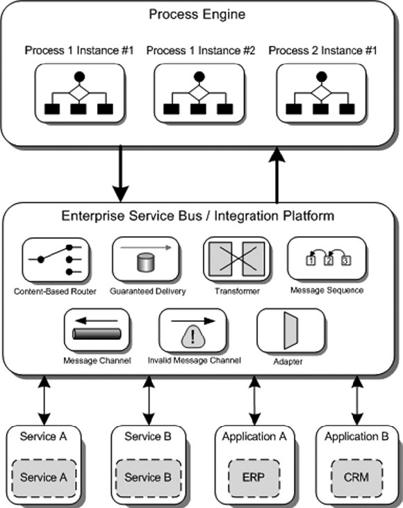
As figure 11.1 shows, the process engine provides an execution environment for processes. This example shows two different processes; process 1 has two instances running, and process 2 has one instance. It’s important to notice that for process 1, each instance has its own state maintained by the process engine. For each invocation to an external service or application, the process engine uses the ESB for the integration logic.
The figure shows a number of patterns that can be implemented in the ESB environment. The ESB communicates with the external services and applications, and does the actual invocation. The optional response message is then routed back to the correct process instance in the process engine.
11.1.2. Designing processes for a process engine
We’ve discussed the execution environment for processes—the process engine—but we haven’t talked about the construction of these processes: the process design. Before a process can be deployed on a process engine, it must first be designed. The industry standard to define a process is the Web Services Business Process Execution Language (WS-BPEL).
Many integration vendors provide a design tool to construct a WS-BPEL process. For example, IBM has the WebSphere Integration Developer product, Oracle has a BPEL Designer for JDeveloper, and Microsoft lets you import and export WS-BPEL from Visio. But there aren’t many open source design tools for WS-BPEL. In section 11.5, we look in more detail at using WS-BPEL with Apache ODE; there you use the Eclipse BPEL plug-in as the open source WS-BPEL design tool.
WS-BPEL is an XML-based language that is standardized by OASIS. WS-BPEL 2.0 has been an OASIS standard since April 2007. The WS-BPEL 2.0 specification is based on the Business Process Execution Language for Web Services (BPEL4WS) specification by BEA, IBM, Microsoft, SAP, and Siebel. And the history doesn’t stop here: The BPEL4WS specification is based on Microsoft’s XLANG and IBM’s Web Services Flow Language (WSFL). The foundation of the WS-BPEL specification is strong, and WS-BPEL is considered the standard technology to specify business processes. WS-BPEL is heavily based on WSDL and XSD; for example, these foundational technologies are used to define variables and partner links for a WS-BPEL process definition.
WS-BPEL defines a large number of activities that can be used to specify a business process. For example, a request/response process always has a receive activity for the incoming message and a reply activity for the outgoing message. But there are also activities to implement process logic, such as an if activity, a while activity, and a forEach activity.
Another example of a process definition language is jPDL, which is used by the JBoss Business Process Management (jBPM) product. jPDL is a graph-oriented programming model, which is based on states and transitions. The open source jBPM project provides an execution environment for processes defined in jPDL, along with an Eclipse-based plug-in to design processes and a web console to manage and monitor processes.
jPDL isn’t an industry standard; it’s a proprietary definition language that is only used in the jBPM project. But it’s a powerful, simple language, and for Java developers it’s a great option to implement a process engine because it’s purely Java based. The jBPM project also provides support for the WS-BPEL standard, so people who are seeking industry standards can also choose this option. Because WS-BPEL support is also based on the Eclipse BPEL plug-in, it’s similar to the Apache ODE example. In section 11.4, we provide a detailed case study implementation that uses Mule and jBPM with jPDL for the process definition.
Now that we’ve discussed two options to define processes with WS-BPEL and jPDL, we can examine the runtime implementation for such processes. Because the process definition involves the invocation of services, a lot of interaction takes place between the process engine and the ESB. Figure 11.2 shows a small implementation example of the interaction between the process engine or the process manager and the services.
Figure 11.2. An abstract overview of the Process Manager pattern. The process manager orchestrates the involved services based on a process description.

We already looked at a more architectural overview of an integration environment with a process engine and an ESB in figure 11.1. Figure 11.2 provides another view of such an environment with an example using the Process-Manager pattern. In this example, the process manager is invoked by a client application that sends a message to an input-message channel. The process implemented involves three external invocations to services A, B, and C. Services A and B use a request/response message exchange pattern; the process manager sends a request message to a specific message channel and waits on another message channel for the service’s response message. The example also shows a fire-and-forget message exchange pattern with Service C. For this service invocation, the process manager sends a message to the input message channel for Service C but doesn’t wait for an answer. This means step 12 in figure 11.2 may not be executed before step 13. (These steps aren’t dependent on each other and therefore may not execute in the order shown.)
Note that this example is oversimplified and doesn’t show the distinction in functionality between a process engine and an ESB as in figure 11.1. But imagine that the message channels are part of the ESB environment and may be enriched with transformations, routing, and message logging. This should give you a thorough overview of the functionality of the Process Manager pattern, so now let’s look at a case study to implement a process engine. Let’s go scuba diving!
11.2. A process engine case study: booking a day of scuba diving
A stay in Hawaii’s SleepingBeauty hotel is an excellent opportunity to go scuba diving for a day. Hawaii provides a wide variety of scuba diving trips that include sharks, dolphins, wrecks, and caves. Currently, the hotel distributes flyers to guests, promoting the idea of booking a scuba diving day trip. This approach seems to be working well, because in the last few months the number of bookings has doubled. But there is one downside: The amount of time the hotel receptionist spends booking trips for hotel guests has also doubled.
The receptionist has to gather the booking request information from the hotel guest, including the date for the trip; the guest’s name and room number; the number of divers; and the guest’s preference for a shark, dolphin, or wreck-and-caves adventure. Then, the receptionist must make a phone call to the diving agency that provides the scuba diving trip of preference. The hotel guest can also request a lunch package for the group of divers, so the hotel’s catering staff must be informed. And finally, a taxi reservation must be made to transport the guests to the diving agency and back. Figure 11.3 summarizes the current process for booking a scuba diving trip.
Figure 11.3. The current booking process for a scuba diving trip, which involves a lot of communication between the hotel receptionist and the other parties in the process

In addition to the amount of time the hotel receptionist has to spend booking each trip, hotel guests must also wait before the final booking information arrives. The hotel manager, Gregor Rest, has ordered your manager (John) to think of an IT solution. Because of your experience in solving integration problems in previous assignments, John has asked you to come up with a solution that requires far less of the receptionist’s time. You asked John to book a room in the SleepingBeauty Hawaii hotel for a week so you can talk to the diving agencies and design a solution that will work for the hotel employees who are involved. John admitted that a stay in Hawaii would be necessary in order to come up with a good design; life as an integration specialist isn’t so bad.
The starting point of your stay is a meeting with the three diving agencies shown in figure 11.3. Before you travelled to Hawaii, you thoroughly investigated the possibility of using a process engine. Because the desired solution includes a number of service invocations, and state must be maintained across these invocations, the choice to use a process engine seems obvious. To implement the same functionality with just ESB message flows would lead to a lot of unnecessary flow-configuration and state-management functionality. You come to the conclusion that the process engine will be used to orchestrate the service invocations and manage the state, and the ESB will be used to invoke the services.
But in order to design a process solution, the cooperation of the diving agencies and the taxi station is vital. During the meeting with the diving agencies, it becomes clear that they’re all willing to invest in a booking service that can be used by Sleeping-Beauty. You suggest that you develop a booking-service solution that all three agencies can use. After an in-depth discussion, all parties agree on an XML message format and the contents of the request and response messages. Great!
In your meeting with the taxi station, things go even more smoothly. The taxi station is already busy developing a booking service that SleepingBeauty can use soon.
The last piece missing is the lunch service, which should be developed within SleepingBeauty. This service will be developed in the coming weeks so it can be implemented and integrated easily with existing applications.
After your stay in Hawaii—which of course included a day of scuba diving—you present your solution design to your manager, John, and hotel manager, Gregor, as shown in figure 11.4.
Figure 11.4. The high-level design of the process to book a scuba diving trip, which automates most communication with the involved parties. The hotel receptionist remains responsible for communicating with the hotel guest.

The high-level design shown in figure 11.4 introduces a booking process definition that defines the orchestration of the scuba diving, lunch, and taxi services. The diagram doesn’t yet include the ESB, which takes care of the logic to invoke the services.
John and Gregor like your solution’s process-based approach and are looking forward to the real implementation. You convince them that it would be wise to develop a quick proof-of-concept to choose between two popular open source process engines: jBPM and Apache ODE. You have only one week to develop this proof-of-concept, so you need to quickly move on to designing and implementing the messages and services that are necessary for the booking process.
11.3. Diving into the messages and services
The booking process consists of multiple message exchanges: the scuba diving request message and the final booking response message are initiated and processed by an application at the reception desk, and there are also message exchanges with the diving agencies and the lunch and taxi services. You have quite a bit of work to do to construct these messages. You must design the request and response messages that you’ll use to implement the message exchanges with the services and the booking process. Because the messages for the service invocations will be implemented with XML, you also need to develop a serialization strategy to marshal the messages to XML and unmarshal the XML messages back to Java objects.
In addition to the message definitions and the XML serialization, you also need to develop stub components to simulate the diving agencies and the lunch and taxi services. (You can’t use the actual services during the proof-of-concept.)
11.3.1. Designing the case study message definitions
When a hotel guest asks the hotel receptionist to book a scuba diving day trip, information is needed to start the booking process. The hotel guest has to provide a name, a room number, the number of divers, the date for the trip, and whether a lunch is needed. The guest must also choose among the four kinds of diving trips: cave, dolphin, shark, or wreck. Note that there are four kinds of trips but only three diving agencies; one of the agencies provides two of the four kinds of trips.
The hotel receptionist enters this information into a simple booking application, which starts the process. The process invokes all the necessary services; the messages involved will be discussed later. The result of these service invocations is a scuba diving booking that holds all the necessary information. Figure 11.5 provides an overview of the scuba diving initial request and final booking messages.
Figure 11.5. The initial message that is needed to start the process and the final booking message that is returned by the process, which holds the necessary information for the scuba diving trip

The final booking message contains all the information related to the diving trip, including the name of the diving agency, the instructor name, the time slots for the taxi ride and the diving activity, and the total price.
The booking message consists of information gathered from the exchange of messages with the scuba diving agency, the lunch service, and the taxi station. Figure 11.6 summarizes the exchange of messages between these three services.
Figure 11.6. The message exchange between the process engine and the involved parties: respectively, the diving agency of choice, the lunch service, and the taxi service
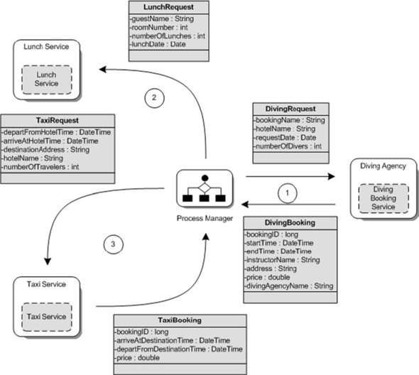
Let’s look more closely at the three message exchanges involved in the booking process:
- Booking the diving agency— The request message holds, among other things, the number of divers and the requested kind of diving experience. The response message from the agency consists of information like a booking number, the starting and ending time of the diving trip, and the name of the agency and the diving instructor.
- Booking lunch— This one-way message exchange sends the guest’s name and room number, the number of lunches, and the date on which the lunch must be prepared to the lunch service of the SleepingBeauty hotel.
- Booking the taxi ride— The request message from the booking process to the taxi station provides enough information to reserve a taxi on a particular date and time, taking into account the number of divers.
The message design described in figures 11.5 and 11.6 provides a good starting point for the implementation of the scuba diving booking process. But how are these messages exchanged with the involved applications and services? There are many different ways to exchange these messages, including the use of Java objects or XML messages.
The use of Java objects can be an efficient message format in a pure Java environment; but the booking process involves two external parties—the diving agencies and the taxi station—so the restriction of a pure Java environment isn’t realistic. Some diving agencies will probably implement the booking service using .NET because their IT environments are Microsoft based. You decide that the message format will be XML. You’ll use JiBX to serialize the Java objects from figure 11.5 and 11.6 into the correct XML format.
11.3.2. Serializing the case study messages to XML with JiBX
In a number of examples of the previous chapters, you used JiBX to serialize Java objects to XML messages and vice versa. In this chapter, the focus is on the implementation of the process engine, so we don’t show JiBX mappings for all the messages defined in section 11.3.1. The other mappings are available as part of the source code distribution for this book. The JiBX mapping for the diving agency request and booking classes is shown in listing 11.1 as an example.
Listing 11.1. Scuba diving request and booking JiBX mappings

You keep the JiBX mappings for the booking process’s messages easy. The Java objects’ attributes are mapped to the same XML
element name. The listing shows a diving request mapping
![]() and a diving booking message
and a diving booking message
![]() . The only Java attribute that can’t be mapped directly is the requestDdate
. The only Java attribute that can’t be mapped directly is the requestDdate
![]() . For the deserialization of the request date, JiBX expects the request-date value to include a time property, as specified
by the standard dateTime XML Schema type. Because you only use a date value for the requestDate, you need to define a deserializer method that converts a date String value in an XML message to a Java Date object.
. For the deserialization of the request date, JiBX expects the request-date value to include a time property, as specified
by the standard dateTime XML Schema type. Because you only use a date value for the requestDate, you need to define a deserializer method that converts a date String value in an XML message to a Java Date object.
This concludes the discussion of the message design and XML serialization for the scuba diving booking process. With the messages defined, you’re missing two parts before you can start implementing the process: the technical design for the integration solution and the stub implementation for the involved services.
11.3.3. Setting the stage for the case study implementation
We introduced the Process Manager pattern earlier in this chapter, but we didn’t yet relate it to the scuba diving case study. You’ll make a design diagram for the case study that includes the Process Manager pattern as the foundation for the integration solution. In the next part of this section, we discuss the implementation of the service stubs that will let you test the case study implementation during the proof-of-concept phase.
Making a design diagram for the scuba diving case study
The process implementation for the scuba diving case study includes the invocation of two external services and one internal service. These services can be invoked directly by the process engine on which you’ll deploy the process. Process engines can use common communication protocols and message formats; most process engines can communicate with SOAP over HTTP, SOAP over JMS, and other protocols and message formats. But process engines are primarily designed to provide an execution and maintenance environment for processes and not to integrate with the existing IT environment (for example, legacy applications). Integration with the IT environment is the main functionality of an ESB. You’ll use this distinction between a process engine and an ESB in your technical design.
The process engine is responsible for implementing the process logic, and the ESB is responsible for integrating with the involved applications and services. Figure 11.7 provides an overview of the technical design for the scuba diving booking process, using this clear distinction between the ESB and the process engine.
Figure 11.7. The process engine orchestrates the diving agency and the lunch and taxi service invocations while using the ESB as a connectivity layer. The ESB implements the functionality to route the messages to the correct service endpoints.

Figure 11.7 lists the application and services and defines the messages exchanged with this application and these services. The names of the messages correspond to the names used in figures 11.5 and 11.6. The process engine is the environment where the process definition is deployed and the service instances are executed. The integration environment or ESB is used to communicate with the application and services.
The starting point for the scuba diving booking process is the hotel reception booking application. The receptionist uses this application to enter the necessary information provided by the hotel guest. When the booking information is entered, the application sends a scuba diving request message to the process-message channel in the integration environment. The process engine retrieves the request message from the process message channel and then starts a new process instance based on the scuba diving booking process design. From there, the process instance completes the process as discussed in section 11.2.
Although you’ll implement the design shown in figure 11.7 with two different process engines and ESBs, the design and implementation for the service stub can be similar. We start by looking at the implementation of these service stubs.
Developing the service stubs for the case study implementation
The starting point of the scuba diving booking process is the booking application used by the hotel receptionist. You’ll use the Swing test client provided with this book to simulate the request message sent by the hotel reception application. The booking process begins by using the diving agency booking services. Because you’ve convinced the diving agencies to use a common message design and protocol, you can use the same interface for all three diving agencies.
public interface DivingAgencyService {

    public DivingBooking processBooking(DivingRequest request);
}
The diving agency service interface provides one method with an incoming diving request and an outgoing diving booking. In the implementation class for this interface, the logic must be implemented to accept a diving request and to process that request into a booking. Because you have to simulate the three external diving agency services for the booking process, you must think of an easy solution to implement three service stubs.
You could implement the diving agency service interface with three different classes. But another way to do this is to define a number of attributes that are unique for one of the three diving agencies and use the Spring container to create three different instances for the same implementation class. Spring can inject the unique values based on the bean configuration; with that mechanism, you can easily simulate all three services. Listing 11.2 shows the diving agency service interface implementation that instantiates the three diving agencies.
Listing 11.2. The common diving agency service interface implementation
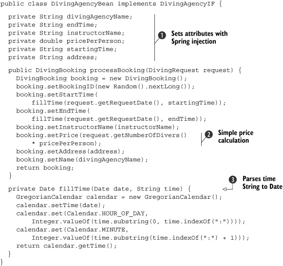
The main part of the diving agency service implementation is the definition of the attributes that are injected by the Spring
container
![]() . These attributes can be used to uniquely identify the specific diving agency. The diving agency name is an important identifier
for the service implementation, as is, for example, the price per person for the scuba diving trip. Listing 11.2 only shows the attribute definition, but the implementation includes getters and setters for all these attributes. The Spring
container uses the attributes’ setter methods to inject the values. The remainder diving agency service implementation is
straightforward. A simple price calculation
. These attributes can be used to uniquely identify the specific diving agency. The diving agency name is an important identifier
for the service implementation, as is, for example, the price per person for the scuba diving trip. Listing 11.2 only shows the attribute definition, but the implementation includes getters and setters for all these attributes. The Spring
container uses the attributes’ setter methods to inject the values. The remainder diving agency service implementation is
straightforward. A simple price calculation
![]() uses the price-per-person attribute value and the number of divers from the request message. To simplify the definition of
the time values in the Spring bean configuration, it uses a String with the format hh:mm. The fillTime method
uses the price-per-person attribute value and the number of divers from the request message. To simplify the definition of
the time values in the Spring bean configuration, it uses a String with the format hh:mm. The fillTime method
![]() converts the time Strings to a Date instance.
converts the time Strings to a Date instance.
The Spring container can now use the implementation class for the diving agency service interface to create three different instances. In the Spring configuration, you can define property elements with name and value attributes that are mapped to the attributes in the Java implementation class. Spring uses the property elements to inject the Java attributes with the values defined in the value attribute. Listing 10.3 configures the three diving agency services with Spring bean configurations.
Listing 11.3. Spring configuration for the diving agencies
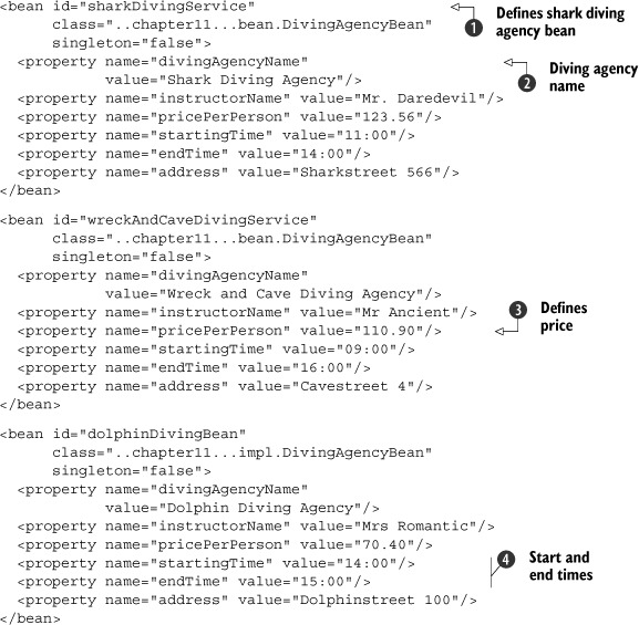
The three diving agency bean configurations start with a bean element that consists of an id, a class, and a singleton attribute
![]() . The id attribute should have a unique identifier value within the Spring container. The class attribute provides the implementation class that Spring will instantiate. And the singleton attribute tells the Spring container whether multiple instances of the bean are allowed. The rest of the listing shows the
property definitions for the three diving agencies. The divingAgencyName attribute, for example, is injected with the value "Shark Diving Agency" for the shark diving agency bean instance
. The id attribute should have a unique identifier value within the Spring container. The class attribute provides the implementation class that Spring will instantiate. And the singleton attribute tells the Spring container whether multiple instances of the bean are allowed. The rest of the listing shows the
property definitions for the three diving agencies. The divingAgencyName attribute, for example, is injected with the value "Shark Diving Agency" for the shark diving agency bean instance
![]() . Another example is the pricePerPerson attribute, which is injected with a value of 110.90 for the wreck and cave diving agency
. Another example is the pricePerPerson attribute, which is injected with a value of 110.90 for the wreck and cave diving agency
![]() . This attribute is implemented in Java as a double, so the Spring container provides the conversion. A final example is the definition of the starting time and ending time
for the scuba diving trip
. This attribute is implemented in Java as a double, so the Spring container provides the conversion. A final example is the definition of the starting time and ending time
for the scuba diving trip
![]() .
.
Because the lunch and taxi services are implemented by one service provider in this case, the implementation of these services is simpler. But in order to provide a complete overview of the services, we discuss these service interfaces briefly. The lunch service uses a one-way interface, as you may remember from section 11.2. This interface is the simplest:
public interface LunchIF {

    public void processLunch(LunchRequestBooking lunchBookinglunchRequest);
}
The lunch-service interface accepts lunch requests and processes them so that on the requested date, the lunches are prepared for the hotel guests. The taxi service interface implements a request/response message exchange pattern and is similar to the diving agency service interface:
public interface TaxiIF {

    public TaxiBooking processTaxiRequest(TaxiRequest request);
}
The taxi service interface accepts requests for taxi rides and processes these requests into a taxi booking response. The implementation of this interface is similar to the diving agency service implementation shown in listing 11.2, except for the large number of attributes. In this book’s source distribution, you can find the full implementation of the taxi service interface.
Now that you’ve defined the messages for the scuba diving booking process, outlined a high-level integration solution, and implemented the services, you can go further with the process engine implementation. In order to show you two process engines and process definition strategies, we’ve split the implementation of the process engine into two sections: section 11.4 discusses the jBPM process engine, and section 11.5 discusses a WS-BPEL implementation with Apache ODE.
11.4. Implementing a process engine with jBPM and jPDL
You can implement a process engine with many different products. To provide a good overview of the possibilities, we look at two different approaches to implementing the scuba diving booking process in the remaining part of this chapter. In this section, we focus on an implementation based on states and transitions with jBPM (http://labs.jboss.com/jbossjbpm), a process engine offered by JBoss. Because this may be your first introduction to jBPM, we start with an overview of how to define processes with the jBPM process definition language (jPDL).
11.4.1. Orchestrating services with jPDL
The jBPM product lets you implement processes that can consist of automatic steps as well as human workflow steps. The definition of these processes is based on jPDL. In addition, you can use WS-BPEL to define processes for jBPM. (We discuss WS-BPEL in section 11.5.) To get up and running with defining processes for jBPM, let’s first look at some foundational concepts.
jPDL is based on a graph-oriented programming implementation technique. Graphs are also known as states; they can be modeled with UML state diagrams. The starting point for a graph or state is the relationship with transitions. When an application or service is in a particular state, you can use transitions to define the conditions required to progress to the next state. Figure 11.8 provides a schematic overview of the relationship between a node (or state) and a transition.
Figure 11.8. A schematic overview of the relationship between nodes and transitions. Nodes can have multiple leaving transitions; a transition always has one node as its destination.

By using nodes and transitions, you can model a basic process graph or state diagram. The nodes in this simple model can represent the current state of the process, and the transitions from one node to another can be used to define the order of states during execution.
But with this model, you can’t easily define complex processes. There are no building blocks you can use to build a process. jPDL provides a basic set of nodes, including start and end states and a task state; see figure 11.9.
Figure 11.9. The basic nodes you can use to define processes with jPDL. The difference between a state and a task is that the latter involves human interaction.

Using the nodes shown in figure 11.9, you can model a more complex process graph or state diagram. For example, you can begin the process design with a StartState node and complete it with an EndState node. To implement logic to choose between three destination states, you can use a Decision node. The standard set of nodes implemented by jBPM also includes a Task node that can be used for workflow logic. With this set of standard nodes, you should be able to design a state diagram. But how can you include custom logic in the process graph? You can do this by using actions that can be defined for a node.
Custom logic can be implemented with an ActionHandler interface implementation that is invoked by the action. Actions can be attached to an event that is registered on a node. The most obvious events occur when the node is entered (node-enter) or left (node-leave) in the process graph. You can develop custom logic that is executed when the node for which you’ve registered the node-enter event is entered during the execution of a process instance. You can register an event for every node in jBPM, so this is the way to implement custom logic for your process. The node can be used as a process element as well; for such a node, you can attach an action implementation directly, without defining an event.
Implementing a jPDL hello world process
You can implement the process graph for jBPM using the jPDL XML Schema. This schema definition consists of the standard set of nodes that jBPM provides and the attributes and elements that can be specified for these nodes. We’ve looked at the theory behind this set of nodes and the use of actions and events, but the discussion will become clearer when we look at an example. Listing 11.4 shows a process definition for a hello world implementation.
Listing 11.4. Hello world implementation with jPDL

The definition of the process graph starts with a process-definition root element that specifies the name of the process with
the name attribute. But the starting point for the process is the start-state definition
![]() . For the hello world implementation, the start element doesn’t have any logic implemented except a transition to the makeHelloWorld node. Note that for more complex processes, it’s possible to define an event child element for a start-state where you can implement logic.
. For the hello world implementation, the start element doesn’t have any logic implemented except a transition to the makeHelloWorld node. Note that for more complex processes, it’s possible to define an event child element for a start-state where you can implement logic.
The start element only transitions the process state to the makeHelloWorld node, which defines some custom logic
![]() . The node definition has an action child element that is executed when the process state reaches the makeHelloWorld node. The action element defines a Java class that implements the org.jbpm.graph.def.ActionHandler interface provided by jBPM. We look at the implementation of this ActionHandler in a moment.
. The node definition has an action child element that is executed when the process state reaches the makeHelloWorld node. The action element defines a Java class that implements the org.jbpm.graph.def.ActionHandler interface provided by jBPM. We look at the implementation of this ActionHandler in a moment.
When the ActionHandler implementation is executed, the process state is transitioned to the end-state element
![]() . This is where the process instance ends. As you can see, the process definition is simple but powerful.
. This is where the process instance ends. As you can see, the process definition is simple but powerful.
This ActionHandler interface defines just one method: execute. The current process state is passed on to the ActionHandler implementation with an ExecutionContext object. The process state consists of information like the process identifier, the variables, and the execution path until this point in the process. Listing 11.5 shows the implementation of HelloWorldHandler, which is used by the makeHelloWorld node from listing 11.4.
Listing 11.5. jBPM HelloWorldHandler implementation

The ExecutionContext that is passed on by the jBPM container provides access to lots of information about the current process instance and the
process template. For this example, the ExecutionContext is mainly used to retrieve and store variables. Assume that the hello world process instance is started with a variable name.
With the ExecutionContext, you can get the ContextInstance variable that is primarily used for variable retrieval and storage
![]() . The ContextInstance provides a getVariable method you can use to retrieve the name variable. With the setVariable method, you can just as easily store a new variable called output with a hello message to the process context instance.
. The ContextInstance provides a getVariable method you can use to retrieve the name variable. With the setVariable method, you can just as easily store a new variable called output with a hello message to the process context instance.
The process instance must be notified that the makeHelloWorld node has finished and the process can be transitioned to the next node. To do this, you call the leaveNode method on the ExecutionContext
![]() . When this line wasn’t added to the HelloWorldHandler implementation, the process state got stuck in the makeHelloWorld node.
. When this line wasn’t added to the HelloWorldHandler implementation, the process state got stuck in the makeHelloWorld node.
Designing processes with the jPDL designer
This concludes the hello world example. In the implementation of the scuba diving booking process, we look in more detail at the runtime execution of a process with jBPM. But jBPM includes another part: a jPDL designer. The jPDL designer is an Eclipse plug-in that you can use to graphically model a process that conforms to the jPDL schema. The jPDL designer consists of a palette where node types and transitions can be selected and provides a drawing canvas where you do the actual process modeling. Figure 11.10 shows the jPDL designer for the hello world process you just defined.
Figure 11.10. The hello world example in the jPDL designer

The palette appears on the left side and the drawing canvas on the right side. As you can see, the modeling elements are synonymous to the XML elements defined in listing 11.4. The graphical elements have a UML annotation–like way to specify the node type. Transitions between nodes are represented as arrows pointing from the leaving node to the target node. In addition to defining the nodes and transitions on the canvas, the jPDL designer provides a properties view that you can use to specify a node’s details. For example, you can specify a node’s action handler and the events configured for a process element. Figure 11.11 shows the properties view for the makeHelloWorld node.
Figure 11.11. The properties view of the jPDL designer, where you can define the handler class to execute custom logic
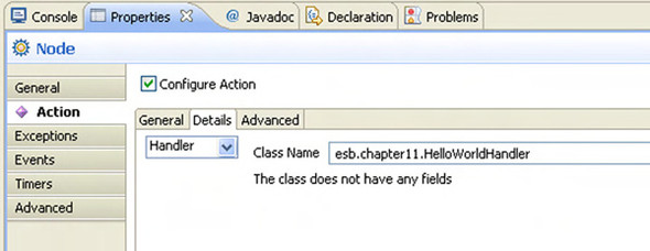
The properties configuration for the makeHelloWorld node specifies the handler class that corresponds with the class shown in listing 11.5. In this view you can also configure other attributes for a node, such as the asynchronous attribute that specifies the way the node is invoked.
Now that you have some background knowledge of jBPM, let’s continue with the design and implementation of the scuba diving booking process.
11.4.2. Implementing the case study with jBPM and Mule
The previous section presented a simple example of process design and implementation with jBPM. With the knowledge you’ve gained about jBPM, you should be able to design the scuba diving booking process implementation for the jBPM process engine. The design should also be based on the clear distinction between the process engine and the ESB, as discussed in section 11.3.3. Figure 11.7, shown earlier in that section, provides a good overview for this discussion.
When you translate this into an implementation with Mule and jBPM, Mule is responsible for the integration with the hotel reception application, the diving agency services, the lunch service, and the taxi service. jBPM will be used for the process definition and the execution of the process instance for the scuba diving booking process. Because Mule comes with jBPM integrated out of the box, you can easily integrate the jBPM process engine with the Mule ESB. Figure 11.12 shows the design for the jBPM case study implementation.
Figure 11.12. The message exchange between the jBPM process instance and the ESB services. The jBPM transport connector that is provided by Mule is used to implement the message exchange. Only one of the diving agency states is shown, because the other two agencies use the same invocation model.
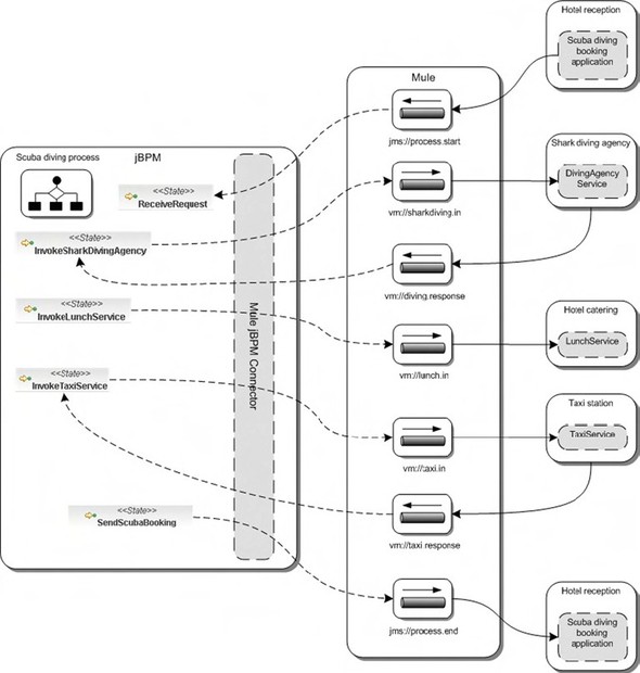
Figure 11.12 can be overwhelming at first sight. Let’s walk through all the aspects of this design for Mule and jBPM, starting with the definition of the process shown at left in the figure. These process elements don’t make up the full process design; they only show the states that receive the first message (ReceiveRequest) and send messages to Mule. Later in this section, we look at the complete process design in the jBPM designer.
The process elements shown here are all state nodes (the shark diving agency state also represents the two other diving agency states); each state invokes a service via the Mule ESB. As you saw in the implementation of the hello world example in section 11.4.1, invocation logic must be implemented in an ActionHandler interface implementation, which can be configured as an event handler for a particular state. Luckily, you don’t have to develop this invocation logic yourself, because it’s provided as part of the jBPM connector provided by Mule. The jBPM connector implements a number of ActionHandler interfaces to communicate with the Mule ESB. For example, InvokeSharkDivingAgency uses a SendMuleEvent action handler to send a diving request to the shark diving agency. Because it’s essential for the scuba diving case study implementation to understand how jBPM and Mule are integrated, let’s discuss this topic in more detail.
Integrating the jBPM process and the ESB message flows
Your Mule distribution includes the jBPM library jbpm-jpdl-3.2.2.jar, which you can look up in the lib/opt folder, and a jBPM transport jar that you can find in the lib/ mule folder. To integrate jBPM in a Mule configuration, you have to include a BPM connector definition such as the one shown in listing 11.6. The jBPM configuration for the scuba diving case study isn’t easy to understand, but this simplified listing should make it clearer.
Listing 11.6. Definition of the jBPM transport in a Mule configuration file
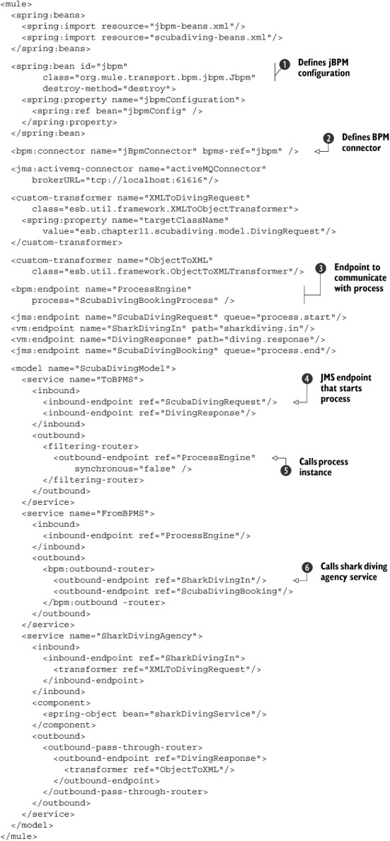
Listing 11.6 shows a simplified version of the Mule configuration for the scuba diving case study to make it easier to understand. Based on this discussion, you’ll be able to understand the full Mule configuration that is part of this book’s source distribution.
To be able to communicate with the process definitions and instances of jBPM from the Mule services, you must define a BPM
connector
![]() . And because the BPM connector is a common entrance to different process engines, you have to configure the bpms-ref attribute. Note that at the time of writing, Mule only provides a BPM connector implementation for jBPM.
. And because the BPM connector is a common entrance to different process engines, you have to configure the bpms-ref attribute. Note that at the time of writing, Mule only provides a BPM connector implementation for jBPM.
The jBPM configuration is defined with a Spring bean that uses the Jbpm class of the jBPM transport to instantiate the jBPM connector
![]() . The only property of the Jbpm bean definition is the jBPM configuration, which is defined in a separate Spring bean file jbpm-beans.xml; this file is imported
at the top of the Mule configuration. We don’t discuss this configuration in this book because this jBPM definition is too
detailed and configures the Hibernate and the jBPM process angine settings. With this configuration, the jBPM container is
instantiated when Mule is started.
. The only property of the Jbpm bean definition is the jBPM configuration, which is defined in a separate Spring bean file jbpm-beans.xml; this file is imported
at the top of the Mule configuration. We don’t discuss this configuration in this book because this jBPM definition is too
detailed and configures the Hibernate and the jBPM process angine settings. With this configuration, the jBPM container is
instantiated when Mule is started.
Now that you have the jBPM transport connector configured, you can define an endpoint you can use to communicate with a jBPM
process
![]() . With the bpm prefix, the endpoint is configured to use the defined jBPM connector. The remainder of the endpoint address configures the
process name of the process definition you want to communicate with—in this case, ScubaDivingBookingProcess.
. With the bpm prefix, the endpoint is configured to use the defined jBPM connector. The remainder of the endpoint address configures the
process name of the process definition you want to communicate with—in this case, ScubaDivingBookingProcess.
Because you have incoming and outgoing messages for the scuba diving process instances, you define ToBPMS and FromBPMS services. ToBPMS defines all the messages sent to the scuba diving process instance, such as the initial request message
![]() . When a JMS message arrives at this queue, the jBPM connector
. When a JMS message arrives at this queue, the jBPM connector
![]() notices that no process instance is running for this message because no correlation identifier is present. The connector then
starts up a process instance for the scuba diving process definition, and this message is sent to the first state in the created
process instance. The DivingResponse endpoint is an example of an endpoint that communicates only with running scuba diving process instances, because this endpoint
is used later in the process.
notices that no process instance is running for this message because no correlation identifier is present. The connector then
starts up a process instance for the scuba diving process definition, and this message is sent to the first state in the created
process instance. The DivingResponse endpoint is an example of an endpoint that communicates only with running scuba diving process instances, because this endpoint
is used later in the process.
In the FromBPMS service, you see that the ProcessEngine endpoint is configured as the inbound endpoint. When you want to invoke a service via Mule from the process definition in
jBPM, you can configure one of the outbound endpoints names
![]() as a target. Listing 11.6 only shows the endpoint for the shark diving agency, but the full implementation also configures the other diving agency
services, the lunch service, the taxi service, and the final booking response endpoint.
as a target. Listing 11.6 only shows the endpoint for the shark diving agency, but the full implementation also configures the other diving agency
services, the lunch service, the taxi service, and the final booking response endpoint.
Configuring action handlers
To get a better overview of the scuba diving process implementation, let’s look at the process configuration for one of the message exchanges. We focus on the invocation of the shark diving agency from the scuba diving process definition. You already saw in listing 11.6 how to configure the SharkDivingIn and DivingResponse endpoints; now, listing 11.7 shows how you can use these endpoint definitions in the jBPM process definition.
Listing 11.7. Snippet of the scuba diving process using action handlers
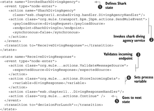
Listing 11.7 shows the part of the scuba diving process definition where the shark diving agency service is invoked and the response is
handled. This snippet of the process definition starts with the declaration of the InvokeSharkDivingAgency state
![]() . This state is triggered when the incoming booking request message consists of a diving interest element value of Sharks.
. This state is triggered when the incoming booking request message consists of a diving interest element value of Sharks.
When the InvokeSharkDivingAgency state is activated by the jBPM process engine, the node-enter event is triggered. When the node-enter event occurs, two action classes are executed: DivingAgencyHandler is an ActionHandler interface implementation that creates the request message you want to send to the shark diving agency service, and SendMuleEvent sends a message to the Mule ESB
![]() . This class is part of the jBPM connector provided by Mule; it expects an endpoint and a payload configuration. The SharkDivingIn endpoint that you define here corresponds with the outbound endpoint in the FromBPMS service from listing 11.6. And the payload source divingRequest relates to the process variable set in DivingAgencyHandler.
. This class is part of the jBPM connector provided by Mule; it expects an endpoint and a payload configuration. The SharkDivingIn endpoint that you define here corresponds with the outbound endpoint in the FromBPMS service from listing 11.6. And the payload source divingRequest relates to the process variable set in DivingAgencyHandler.
After the divingRequest variable is sent to Mule’s SharkDivingIn endpoint, the scuba diving process remains in the InvokeSharkDvingAgency state. But when the shark diving agency service responds with a diving booking message in the DivingResponse endpoint, the scuba diving process is triggered again. This means the process state transitions to ReceiveDivingResponse.
When the node-enter event of the ReceiveDivingResponse state is triggered, four action classes are executed. The first, ValidateMessageSource, checks the inbound endpoint name where the incoming message arrives at the process instance
![]() . This action handler is also part of the jBPM transport connector and checks whether the source indbound endpoint of the
incoming message is equal to DivingResponse. When the endpoint-name check is valid, the payload of the incoming message is stored in the process variable divingResponse
. This action handler is also part of the jBPM transport connector and checks whether the source indbound endpoint of the
incoming message is equal to DivingResponse. When the endpoint-name check is valid, the payload of the incoming message is stored in the process variable divingResponse
![]() . The DivingResponseHandler then uses the divingResponse variable to set the corresponding values for the process booking result variable bookingResponse.
. The DivingResponseHandler then uses the divingResponse variable to set the corresponding values for the process booking result variable bookingResponse.
The last action handler is also a class provided by Mule’s jBPM transport. The Continue class does nothing more than instruct the process engine to transition the process instance to the next state
![]() . In this case, this means the process instance transitions to the decisionForLunch state. Note that in the previous state, InvokeSharkDivingAgency, the state transition is triggered not by an action handler but by receiving the diving response message. Because you don’t
expect a response message to arrive to transition the process instance for the ReceiveDivingResponse state, you automatically transition the state by using this Continue action handler.
. In this case, this means the process instance transitions to the decisionForLunch state. Note that in the previous state, InvokeSharkDivingAgency, the state transition is triggered not by an action handler but by receiving the diving response message. Because you don’t
expect a response message to arrive to transition the process instance for the ReceiveDivingResponse state, you automatically transition the state by using this Continue action handler.
We’ve discussed the details of integrating the jBPM process engine with Mule in this section. In addition to configuring jBPM in the Mule configuration, you now know how to invoke message flows in Mule from the jPDL process definition. In the next section, we look at the jDPL process definition for the scuba diving case study.
Designing the scuba diving process with jPDL
Now that we’ve discussed the integration between jBPM and Mule, let’s look at the process definition for the scuba diving booking process. You already saw some of the process elements in figure 11.2, which focused on the communication between the jBPM process and the Mule message flows. In addition to the states that invoke services on the Mule ESB, you also need conditional logic. For example, you need to invoke the correct diving agency based on the hotel guest’s diving interest.
To design a process definition with jPDL, you don’t have to hand-code the XML definition as in listing 11.7. The jBPM project provides a jPDL Eclipse plug-in, which offers a graphical environment where you can drag and drop and configure the process elements into a process definition. To install the jPDL designer, first download the full jBPM jPDL suite from the jBPM website (http://labs.jboss.com/jbossjbpm). The suite contains the Eclipse plug-in as well as a JBoss server to run the jBPM container for jPDL processes. After you’ve unpacked the jDPL suite distribution, copy the contents of the designer/eclipse directory to your Eclipse installation directory. When you start up Eclipse, the jPDL designer will be available without any additional installation.
Figure 11.13 shows the whole process definition as designed with the jPDL designer.
Figure 11.13. The process definition for the scuba diving booking process as designed with the jPDL Eclipse plug-in, which is provided by the jBPM project
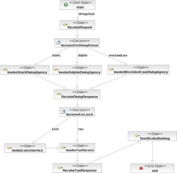
Like every other process definition, the scuba diving booking process defines start and end states. They are the default starting and ending points for a process definition with jPDL. The first element that implements logic is the ReceiveRequest state, which handles the booking request message. The action handlers defined for this state are similar to the ones you saw in listing 11.7. Note that these action handlers can only be found by opening the resources/chapter11/jbpm/scuba-process.xml file in Eclipse with the jPDL designer installed. First the endpoint of the arriving message is checked, then the incoming message is stored as the booking-process variable, and finally the state of the process instance is forced to transition with the Continue action handler to the decisionForDivingSchool decision node.
Based on the hotel guest’s interest, one of the diving agencies is invoked to book a scuba diving trip. Note that you set a booking variable in the process context in the ReceiveRequest state, which consists of the booking request that you can use to make this decision. With the decision element, you can set conditions on the transitions leaving the decision. To make it easy for the process developer, the jPDL designer of jBPM provides a properties view on a transition to set the condition. When you click the wreckandcave transition, you see a properties view similar to the one shown in figure 11.14.
Figure 11.14. The properties view of a transition leaving a decision node. This example shows a script expression that checks whether the diving interest is equal to Wrecks or Caves. If the expression evaluates to true, then this transition is executed.

On the Condition tab, you can set the condition type to Script and fill in the condition logic for the transition. Note that the decision is implemented with a structure similar to the JSP expression language. The main difference is that the decision notation uses a #{..} structure, instead of the ${..} structure of the JSP expression language. The condition shown in figure 11.14 evaluates the interest attribute of the booking variable to see if its value equals Wrecks or Caves. You use a similar expression for the conditions of the shark and dolphin transitions that leave the decisionForDivingSchool node (see figure 11.13). For the shark transition, the expression is #{booking.interest == 'Sharks'}, and for the dolphin transition it’s #{booking.interest == 'Dolphins'}.
The decision node makes sure the scuba diving booking request is forwarded to the correct diving agency state. Three diving agency state nodes are included in the scuba diving process definition; you saw the action handlers for the InvokeSharkDivingAgency state in listing 11.7. But we didn’t discuss the custom action handler that fills and sets the request message process variable. Listing 11.8 shows the implementation of the DivingAgencyHandler.
Listing 11.8. DivingAgencyHandler implementation that sets the request message
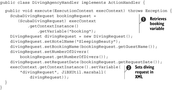
The DivingAgencyHandler class implements the ActionHandler interface of jBPM, because that’s a requirement to be able to attach a handler implementation to a state. The information
needed in the request message to the diving agencies is provided by the hotel guest’s booking request, so first the booking
object is retrieved from the process context
![]() . With the ScubaDivingRequest instance, you can copy the necessary information from the booking request to the scuba diving request message.
. With the ScubaDivingRequest instance, you can copy the necessary information from the booking request to the scuba diving request message.
To be able to use the diving request message in the SendMuleEvent action handler, you must set the object in the process context
![]() . Because the communication between the jBPM container and the Mule ESB is implemented with XML messages, you use JiBX to
serialize the request message to XML. Note that it’s not necessary to use XML messages here; it’s an implementation decision.
You also could use serializable Java objects. But to have a clear distinction between the process engine and the ESB, XML
may be a good choice.
. Because the communication between the jBPM container and the Mule ESB is implemented with XML messages, you use JiBX to
serialize the request message to XML. Note that it’s not necessary to use XML messages here; it’s an implementation decision.
You also could use serializable Java objects. But to have a clear distinction between the process engine and the ESB, XML
may be a good choice.
In listing 11.7, you saw the XML configuration of the InvokeSharkDivingAgency state. This XML configuration provides a good overview of the events and action handlers configured for that state node. But with the jPDL designer, you don’t have to code this XML configuration yourself. The action handlers can be configured in the properties view of the state node; for example, figure 11.15 shows the configuration for the InvokeSharkDivingAgency state node.
Figure 11.15. The properties view of the InvokeSharkDivingAgency state, which shows the configuration of the action handlers executed for this state
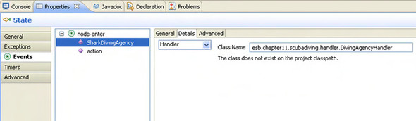
The action handlers shown in figure 11.15 correspond with the XML configuration from listing 11.7. First the DivingAgencyHandler action handler is executed, which sets the diving request message; then, the SendMuleEvent action handler sends the diving request to the Mule ESB. In this case, the actions are implemented with handler classes, but an expression handler type option is also available. You can use the expression handler type for simple logic, like assigning a variable value.
The next part of the scuba diving booking process is a decision that determines whether the hotel guest requested lunch. Based on the outcome of this decision, the lunch handler is invoked or not. You can configure the lunch decision node like the decision example shown in figure 11.14. In the booking request, you use a lunch-included attribute to determine whether a lunch is requested. The decision is configured with the expression #{booking.lunchIncluded == true}. The implementation of the lunch handler is similar to the diving agency handlers, so we don’t look at the details here. The code is included in the source distribution of this book.
The final part of the process definition as shown in figure 11.13 is the taxi node. Just like the diving agency nodes and the lunch node, the taxi node uses a number of handler classes to communicate with the taxi service via the Mule environment. For details about the taxi-handler class implementation, see the book’s source distribution. The end state completes the scuba diving booking process definition.
We haven’t discussed every part of the process implementation, but you’re already familiar with the remainder, which includes the Mule configuration for the Spring bean invocation of the diving agencies and the lunch and taxi service. Because the full implementation code is available in the book’s source distribution, we don’t show listings of every part of the solution.
Testing the jBPM scuba diving process
The next step is to test the scuba diving process with the jBPM container and the Mule ESB. To use the jBPM transport provided by Mule, you have to deploy the process definition as part of the Mule message flow. Remember that you configured a jBPM connector as part of the Mule configuration in listing 11.6. With this configuration, the jBPM container will run in the same virtual machine as the Mule ESB container. Don’t forget to start ActiveMQ before you start Mule.
The testing procedure for the scuba diving process isn’t that different from previous examples. You can use the Swing test client to trigger the scuba diving process as a simulation of the hotel reception application. You can also use the unit test ScubaDivingTest to trigger the process. But first, you must deploy the message flow deliverable to the Mule distribution by executing the scubadiving Ant target in the Ant build script available in the resources/chapter11 directory. This constructs a jar file that contains the Mule configuration as well as the jBPM process definition and starts the Mule container. When the Mule container is started, you can use the Swing test client to send the diving-request message.
The diving request message triggers the Mule message flow and the scuba diving process. Looking at the log output in the Mule command dialog, you see the execution of the process definition. Eventually, the booking response message of the scuba diving process is received in the Swing test client, which means the process has run successfully.
This is a good time to practice with the process definition of the scuba diving process. Try to change the process flow or add new action handlers to the process definition; doing so will help you to better understand how to use jBPM with Mule.
When you’re ready, the next section contains a detailed description of the Apache ODE implementation. For Apache ODE, we look at an alternative process definition language, WS-BPEL, which is considered to be the industry standard for defining processes.
11.5. Implementing a process engine with Apache ODE and WS-BPEL
Implementing a process engine that can be integrated with ServiceMix is just as easy as integrating jBPM with Mule. The main difference is that ServiceMix implements the JBI specification and therefore provides a pluggable container for every process engine that can be deployed as a JBI service engine. The Apache ODE project provides such a JBI service engine for a WS-BPEL 2.0–compliant process engine.
In this section, we focus on implementing the scuba diving booking process with Apache ODE and WS-BPEL. First, we introduce the WS-BPEL specification for readers who aren’t familiar with this specification. Then, we examine the implementation of the scuba diving process in WS-BPEL.
11.5.1. Orchestrating services with WS-BPEL
The WS-BPEL 2.0 specification is standardized by OASIS and reached the OASIS standard predicate in April 2007. WS-BPEL is a process definition language that is heavily based on XML standards like WSDL 1.1, XML Schema 1.0, and XPath 1.0. It’s no surprise that the definition language is also specified in XML. As a process developer or designer, you’re mainly interested in the WS-BPEL elements that you can use to define your processes. Figure 11.16 provides an overview of the WS-BPEL language constructs, with screenshots from the Eclipse BPEL designer we discuss later in this section.
Figure 11.16. The primary WS-BPEL 2.0 language constructs, which you can use to define processes. These elementary elements can be nested within the sequence and flow control elements.
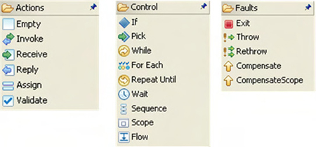
As you can see, more process elements are available than in the jPDL language. jPDL only provides elementary process constructs like state and transition; the rest of the functionality can be implemented with handler classes. With WS-BPEL, you also have standard elements to validate messages and to assign message values to variables and vice versa.
Most of the process element names speak for themselves, but let’s discuss the main elements in more detail. Every process definition needs to start with an element that receives a message. In most cases this is the Receive element, but when you need more flexibility to distinguish between different types of incoming messages, you can also use the Pick element. The Pick element is able to receive messages from different parties. Another common construct is the Reply element, which sends a response message to the service that sent the message that started the process via the Receive element.
The best way to understand how to define a process with WS-BPEL is to look at a hello world example. This example uses the Eclipse BPEL designer plug-in, which is provided by the Eclipse project. You can install the plug-in by using the Eclipse BPEL project’s update site, as described at http://download.eclipse.org/technology/bpel/update-site/. The installation procedure installs all the plug-ins and frameworks you need to run the BPEL designer plug-in from your Eclipse environment. The hello world example that we developed with this plug-in is shown in figure 11.17.
Figure 11.17. A hello world process, designed with the BPEL designer plug-in of the Eclipse BPEL project. The process copies the name of the incoming message to the response message with the prefix hello.
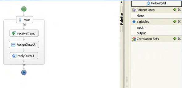
Figure 11.17 shows a receiveInput element of type Receive, which expects a message with only one string element. The interface of the Receive element is defined by the client-partner link shown at right. A partner link is linked to a WSDL definition—in particular, to the port type of a WSDL definition. A partner link has a clearly defined interface, with an incoming message and an optional response message. In addition to the interface definition, a partner link also specifies the role it plays for the process. The role can be a process role, which means an external partner sends a message to the process; or a partner role, which means the process invokes an external service partner. Remember that partner links are the way to define the interaction between the process and external services. Figure 11.18 shows the properties view of the client partner link.
Figure 11.18. The properties view of the client-partner link defined as part of the hello world process definition. Notice that the role defines that an external partner will invoke the process.

You define two things for the client partner link: the role and the port type of a WSDL interface. In this case, you have an interface of an incoming and outgoing String message, just as you would expect for a hello world example. For the receiveInput activity in the hello world process, you configure the client partner link, the operation that is used (this can only be process for this interface), and the process variable input where you store the incoming message. When a String message arrives at this hello world process, the value is assigned to the input variable.
The next activity in the hello world process is the assignOutput element, which uses the Assign construct. With the Assign activity you can set a specific value for a variable and copy values from one variable to another. In this example, you want to copy the value of the input variable to the output variable and add the prefix hello. With the Eclipse BPEL designer, you can configure this functionality in the properties view of the Assign activity, as shown in figure 11.19.
Figure 11.19. The properties view of the Assign activity that is used in the hello world process. In this example, you copy the input variable to the output variable with a hello prefix by using an XPath expression.
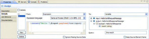
In Figure 11.19, you can see that the output variable is presented in a tree structure in the Assign activity’s properties view. In this case, you have a simple message, but this tree structure can become complex. This is an easy way to specify an element of a variable that you want to copy. On the From side of the assign statement, you can also use an XPath expression to retrieve a specific element of a variable. The Eclipse BPEL designer even provides code completion for the definition of the XPath expression. With the $ prefix, you can retrieve the input variable and define the rest of the XPath expression.
The last part of the hello world process is the Reply activity, which also uses the client partner link, just as you saw with the Receive activity. The Reply activity also uses the process operation and is configured to return the output variable.
For now, this should provide enough background for you to be able to implement the scuba diving process case study. Let’s not wait any longer and jump into the implementation of the case study with Apache ODE and ServiceMix.
11.5.2. Implementing the case study with Apache ODE and ServiceMix
As we stated earlier, Apache ODE provides a WS-BPEL 2.0–compliant process engine that can also be deployed as a JBI Service Engine on ServiceMix. The other deployment platform that Apache ODE supports is Axis2; it can also be deployed on application servers like Tomcat. In this section, we focus on the JBI service engine distributable of Apache ODE, because we want to have integration with the ServiceMix container.
The only thing you need to do to deploy the Apache ODE Service Engine in the ServiceMix container is to copy the ode-jbi-1.2.zip file from the libraries/apache-ode-jbi-1.2 directory, created by the setup script described in chapter 3, to the hotdeploy directory of the ServiceMix distribution, esb/apache-servicemix-3.2.1.
Choosing the JBI components for the scuba diving case study
Before we look at the implementation of the scuba diving process, let’s think about the different JBI components required for this solution and the message exchanges you need to implement. First, you must be able to send a scuba diving request message to the ServiceMix container from the hotel reception application. In the Mule implementation, you used JMS to provide asynchronous messaging capabilities for this message exchange; let’s use the JMS binding component for the ServiceMix example.
The scuba diving process needs an in-out message exchange, because it sends a reply back to the requesting service. You need to add a pipeline that converts the JMS consumer’s InOnly message exchange into an in-out message exchange for the BPEL process. The last thing you have to decide is how to provide connectivity to the diving agency, lunch service, and taxi service Spring beans. You defined JiBX mappings in section 11.3, so the easiest way to communicate with the Spring beans is to use the Bean Service Engine. Another option would be to use the JSR181 Service Engine, but this component uses its own marshaling and unmarshaling implementation; you use the ServiceMix Bean component for this example. Figure 11.20 provides an overview of the JBI components for the scuba diving process case study.
Figure 11.20. JBI components needed to implement the scuba diving process case study. This design diagram also shows the interaction and part of the component implementation.

We’ve discussed most of the components shown in figure 11.20. Note that divingAgencyService represents the three Spring beans that implement the diving agencies. Some of the component implementations need no explanation, because you’ve used them in other examples. ScubaDivingProcess is the central component for this case study implementation, and we look at this implementation first.
Designing the scuba diving process with WS-BPEL
The first step in designing the scuba diving process with the Eclipse BPEL Designer is to define a WSDL interface for the BPEL process. In section 11.3, we defined the request and response messages for the process, so this shouldn’t be a difficult exercise. With the Eclipse Web Tools Project (WTP) distribution, you have a fancy WSDL editor available, so you don’t have to code the WSDL definition. Figure 11.21 shows the WSDL interface of the scuba diving process.
Figure 11.21. The WSDL interface you need to define for the scuba diving process. The message definition corresponds to the message design from section 11.3.

Figure 11.21 shows the input and output messages for the scuba diving process and a detailed view of the ScubaDivingRequest input message. In addition to the process interface, you also need to define the WSDL interfaces for the invocation of the diving agency and the lunch and taxi services. Luckily, you defined all the message definitions in section 11.3; you just have to create three additional WSDL interfaces that correspond with these message definitions.
Now that you’ve defined the WSDL interfaces for the scuba diving process, you can design the WS-BPEL process. In the hello world example, you saw the Eclipse BPEL Designer, which you can use to design the WS-BPEL process. Figure 11.22 shows the WS-BPEL process.
Figure 11.22. The WS-BPEL implementation of the scuba diving process in the Eclipse BPEL Designer. The WS-BPEL process diagram includes a smaller diagram of the partner links and variables.
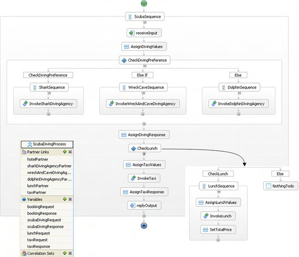
Figure 11.22 shows the complete WS-BPEL design for the scuba diving process, including the partner links and variables. You can look at the WS-BPEL scuba diving process in Eclipse (with the Eclipse BPEL plug-in installed) by opening the resources/chapter11/scubadiving-bpel/resources/ScubaDivingProcess.bpel file. The primary part of the process implementation is a sequence of invocations that are executed. Every invocation needs its own set of variables for the input and output messages, and this is reflected in the names of the variables. You define partner links for every target service and for the process itself. Although most of the WS-BPEL implementation is self-explanatory, we need to discuss two parts.
First, we need to mention the pitfall of variable initialization required by the Apache ODE process engine. For example, when you want to invoke the shark diving agency service with the scubaDivingRequest variable, you must initialize the variable before you can copy values to its elements. Figure 11.23 shows the properties view of the AssignDivingValues activity where you initialize the scubaDivingRequest variable.
Figure 11.23. An example of the initialization of the scubaDivingRequest variable in the AssignDivingValues activity of the scuba diving process
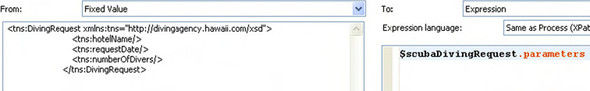
You have to initialize the scubaDivingRequest variable with a fixed string value that represents an empty diving-request message. After you’ve initialized the variable, you can copy values to it with an Assign activity.
Second, we need to discuss the implementation of the If element—for example, the CheckDivingPreference activity. The If activity is an if-elseif-else language construct that can be used to execute a different set of activities based on a condition. In the example, you need to determine the hotel guest’s diving interest in order to invoke the correct diving agency. In the properties view of the if, elseif, and else transitions of the CheckDivingPreference activity, you can use XPath expressions to define the conditions. Figure 11.24 shows the XPath expression for the shark diving agency execution path.
Figure 11.24. The definition of a condition for an If activity. This example checks whether the diving interest equals shark, to determine the correct diving agency to invoke.
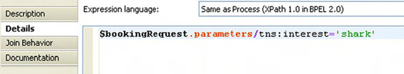
The XPath expression shown in figure 11.24 is similar to the XPath expression in the Assign activity of the hello world example. The interest element is selected with an XPath expression, and the value is compared to the shark literal.
With these additions, the process definition is straightforward and not much different from the hello world example. In addition to the WSDL interfaces and the BPEL process, you need to define the integration configuration with the ServiceMix container. This configuration file is named deploy.xml and defines the relationship between the partner links of the process and the ServiceMix services. The configuration of deploy.xml for the scuba diving case study is shown in listing 11.9.
Listing 11.9. Configuration to integrate Apache Ode with ServiceMix
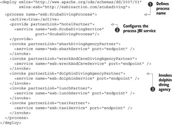
The deployment configuration file begins with the definition of the WS-BPEL process that you need to integrate with the ServiceMix
services
![]() . The process name ScubaDivingProcess and the corresponding namespace are declared as part of the WS-BPEL process definition.
. The process name ScubaDivingProcess and the corresponding namespace are declared as part of the WS-BPEL process definition.
The remainder of the configuration defines the relationship between a partner link of the scuba diving process and the corresponding
ServiceMix service name. The first relationship is made between the hotelPartner partner link and the ServiceMix service name that you use to invoke the process
![]() . By setting ScubaDivingService as the target service in an xbean.xml configuration file, you can invoke the scuba diving process from a ServiceMix JBI component.
This service name must be used by the EIP Service Engine to call the process.
. By setting ScubaDivingService as the target service in an xbean.xml configuration file, you can invoke the scuba diving process from a ServiceMix JBI component.
This service name must be used by the EIP Service Engine to call the process.
The configuration for the pipeline has one pitfall, as shown in the following code snippet:
<eip:pipeline service="esb:scubaPipeline" endpoint="endpoint">
  <eip:transformer>
    <eip:exchange-target service="esb:ScubaDivingService"
                         operation="process"/>
  </eip:transformer>
  <eip:target>
    <eip:exchange-target service="esb:scubaResponse" />
  </eip:target>
</eip:pipeline>
In addition to the service name, you must specify the operation that you want to invoke on the process interface. As you saw in figure 11.21, only one operation is specified on the process interface, and that is the process operation. This operation name is also used in the pipeline definition.
The other partner links to ServiceMix service mappings are invocations from the process to ServiceMix services. An example
of such a mapping is the invocation of the dolphin diving agency
![]() . In the xbean.xml configuration file of the Bean Service Engine, dolphinService is configured as a service with an endpoint named endpoint. Notice that the port attribute refers to this endpoint name. We’ve now discussed all the aspects of the scuba diving WS-BPEL process.
. In the xbean.xml configuration file of the Bean Service Engine, dolphinService is configured as a service with an endpoint named endpoint. Notice that the port attribute refers to this endpoint name. We’ve now discussed all the aspects of the scuba diving WS-BPEL process.
Testing the Apache ODE scuba diving process
Now that you’ve implemented all the JBI components for the scuba diving case study, you can think about testing the solution. We didn’t discuss all the JBI components, but you can find the remaining configurations in the book’s ServiceMix source distribution. With the knowledge you’ve gained by reading the previous chapters, it will be easy to understand the component configurations we didn’t discuss in detail. Take your time and look at the all the configurations before you proceed with the testing activity.
Testing the scuba diving case study isn’t that different from the previous examples in this book, although you do have to make sure you’ve installed the Apache ODE JBI distribution to the ServiceMix container as described in the case study implementation. When the Apache ODE JBI component is installed, you can start up the Service-Mix container, and the Apache ODE process engine will be available for deploying WS-BPEL processes.
To deploy the scuba diving integration solution to the ServiceMix container, you have to run the Ant script provided in the resources/chapter11 directory of the ServiceMix source distribution. This Ant build script creates a service assembly that contains all the service units from figure 11.20. The Ant script also deploys the service assembly to the ServiceMix container.
Now, you can use the Swing test client (also provided in the code distribution) to send a scuba diving request message to the ServiceMix container. Eventually, you’ll receive a response message from the process containing detailed information about the scuba diving booking, including the total price and the start and end times for your trip.
11.6. Summary
This chapter provided a lot of information about process engines in general and jBPM and Apache ODE specifically. Because these process engines can be integrated easily with Mule and ServiceMix, respectively, you have a powerful integration environment in your hands. You saw much of the functionality an ESB can provide in the previous chapters; with the addition of the process engine, you can support stateful process flows, which provide state management, service orchestration, and versioning out of the box.
jBPM and Apache ODE both provide support for WS-BPEL, and jBPM also supports jPDL to define processes. WS-BPEL has the advantage of being an OASIS standard; it’s widely supported in commercial process-engine products and a number of open source process engines. Because WS-BPEL is based on XML standards like WSDL, XSD, and XPath, incoming and outgoing messages should be defined with XML. The integration with ServiceMix is natural, because this ESB is also dependent on XML.
jPDL has no dependency on XML; you can also use Java objects to implement the request and response messages. But jPDL isn’t an industry standard and is only supported by the jBPM process engine. Because Mule also supports multiple message formats, with Java objects and XML messages as the most obvious choices, the integration with jBPM is seamless. When you’re in a Java environment, jPDL can be an excellent choice because you don’t have to marshal and unmarshal XML messages. But the main objective of this chapter was to show two examples of process engines, integrated with an ESB environment; you should decide for yourself which process engine fits your needs. In the case study implementations, you saw that both process engines provide excellent tool support and nice ESB integration functionality.
The end of this chapter also means the end of this book. We’ve given you a good overview of the functionality Mule and ServiceMix can provide, including great routing, transformation, connectivity, and process-engine support. We’ve shown you that Mule and ServiceMix are good counterparts for commercial ESB products and deserve to be included in your short list when you’re choosing an ESB product for your organization. Open source projects are changing at a fast pace, so we advise you to keep our website (http://www.esbinaction.com) among your favorites; we’ll provide updates for the book examples when new versions of Mule and ServiceMix (and other open source ESBs, like Apache Synapse and Spring Integration) arrive.