
6
Femtosecond Laser-Inscribed Fiber Bragg Gratings for Sensing Applications
Abstract
This chapter presents the state of the art of femtosecond laser–induced fiber Bragg gratings for sensing applications. It summarizes the laser-material processing mechanisms for dielectric modification with femtosecond pulse duration sources, techniques for grating inscription with said sources, and applications of femtosecond laser–induced gratings in waveguides for strain, temperature, and chemical sensing in harsh environments.
Keywords
Fiber Bragg grating; Fiber optic sensor; Laser-material processing; Nonlinear optics; Ultrafast laser sources
6.1. Introduction
Since their invention in the late 1970s [1] and their implementation in the telecom industry and for sensing applications in the 1990s [2,3], fiber Bragg gratings (FBGs) have demonstrated themselves, perhaps more strongly than any other fiber optic component, to be a robust and versatile technology. In the telecom domain, FBGs are mainly used for wavelength stabilization of laser diodes needed to pump optical amplifiers within repeater links of terrestrial and submarine long-haul optical networks. They have also been used for wavelength division multiplexing, facilitating extremely high density communication channels and terabyte levels of data over a single fiber. Specialized chirped FBGs have been used to compensate for chromatic dispersion present on existing long-haul fiber links extending the effective range of high-speed data connections. FBG-related systems have been widely deployed in optical networks, making them one of the core technologies alongside the laser, optical fiber, and optical amplifier [4].
As sensors, FBGs possess all the advantages of other fiber optic–based sensing techniques over more traditional electrical sensor technology, namely, their small size, passive nature, immunity to electromagnetic interference, and resistance to harsh environments and corrosion, as well as optical network multiplexing techniques to arrive at distributed sensing capabilities. Essentially the FBG sensor acts as either a temperature or a strain sensor with important advantages such as the ability to support simultaneous measurement of strain and temperature and multiaxis strain. They have been used in numerous areas of structural health monitoring such as in civil structures, robotics and aerospace, and naval vehicles incorporating “smart skins.” Sensing architectures can be designed to measure pressure, corrosion, moisture, vibration, and other environmental effects that ultimately relate to strain and temperature changes in the optical fiber.
FBG sensors have traditionally been fabricated with ultraviolet (UV) lasers that are used to photoinscribe the gratings into a telecommunication optical fiber that is photosensitive to UV radiation. The development of FBG inscription techniques using ultrafast femtosecond pulse duration lasers has provided advantages over the UV approach in that they can be applied to virtually any optical material, opening up more opportunities for FBG sensors, especially for applications in harsh environments where other optical materials are more suitable. Grating inscription using these new sources is not limited to optical waveguides that are sensitive to UV radiation, such as germanium-doped silica telecommunication fibers, but can be used to process any optical material that is transparent to low-signal femtosecond pulse duration radiation. By choosing exposure parameters correctly, one can make grating structures that are stable up to the glass transition temperature of the material, making them ideal for high-temperature sensing applications.
In this chapter, a brief description of the first-generation UV laser–based Bragg grating technology and how it has been applied to sensing will be presented. Femtosecond laser–induced gratings will then be discussed by initially presenting a review of femtosecond laser–material interactions and induced index change mechanisms followed by techniques that exploit these processes for grating inscription. Unique attributes of the femtosecond laser–induced gratings made by the respective methods will be discussed. The chapter will then close with a description of various sensing applications of femtosecond Bragg gratings.
6.2. The Fiber Bragg Grating
The FBG is an optical filtering device present within the core of an optical fiber waveguide. It reflects light of a specific wavelength depending on the spacing of a periodic variation or modulation of the refractive index that forms the grating within the waveguide core. This grating structure acts as a band-rejection optical filter passing all wavelengths of light that are not in resonance with it and reflecting wavelengths that satisfy the Bragg condition of the core index modulation, namely,
where λB is the FBG Bragg resonance or Bragg wavelength, neff is the effective refractive index seen by the guided mode of light propagating down the fiber, and ΛG is the period of the index modulation that makes up the grating. A diagram of an FBG is shown in Fig. 6.1.
Typically, the core refractive index modulation Δn is created by imprinting a one-dimensional hologram or interference pattern into the photosensitive glass core of the fiber using a high-powered laser. This was first demonstrated using a highly coherent 488-nm Ar+ laser source whereby the interference between the input beam and the partial reflection from the cleaved fiber end face resulted in a standing wave pattern within the core of a germanium-doped telecommunication optical fiber [1]. The high-intensity portions of the standing wave within the fiber created an index change resulting in modulation of the index along the length of the Ge-doped fiber core. Later studies showed that these index changes were generated by two-photon absorption excitation of an oxygen vacancy defect site [5]. The ΛG of the Hill gratings created by this approach was dependent on the wavelength of the irradiation and therefore limited in pitch variation. The next major advancement in FBG fabrication came when high-intensity UV inscription light delivered transversally along the length of the fiber core was used to inscribe the FBG [6]. The incident UV light from a coherent tunable dye laser source was spatially modulated using a bulk interferometer to create the holographic pattern that was imprinted into the photosensitive fiber. Later a specialized transmission diffraction grating commonly known as a phase mask [7] was used to generate the interference pattern of UV light in the fiber.

Because of its simplicity and ease of alignment, the phase mask approach for grating inscription was widely adopted, especially in industrial settings. Typically, the spatial modulation of the writing beam is realized by transmitting the UV light through the phase mask, which is a transmission diffraction grating that is precisely etched to nullify the transmitted zero order. The light exiting the mask is mostly coupled into the resulting ± 1 orders, which immediately interfere after the phase mask creating a spatial modulation of the beam that can be photoimprinted along the length of the core of the Ge-doped optical fiber [7].
The index change associated with UV light exposure of Ge-doped silica is thought to arise from a single UV photon absorption process that excites oxygen deficiency defect centers having absorption bands around 244 nm [6]. For large index changes (>5 × 10⁻⁴), it is likely that defect formation is also accompanied by densification of the glass matrix [8]. These positive changes in the refractive index, often referred to as type I index changes, have a temperature-dependent decay, which can be characterized using a power law [9]. This decay is the result of the thermal depopulation of trapped excited states that are created during the grating formation. At elevated temperatures, carriers in the shallowest traps can absorb enough thermal energy to escape and return to the ground state. The remaining carriers are thus associated with more stable states, which can also relax to the ground state at higher temperatures. As the most unstable carriers decay at lower temperatures, type I gratings are annealed at temperatures higher than their designed operating temperature to obtain long-term stability in their reflectivity.
Using high peak power pulsed UV laser sources, such as nanosecond pulse duration krypton/fluoride-based excimer lasers, high-reflectivity gratings (>99%) have been inscribed with a single laser pulse [10]. These gratings result from a threshold-dependent multiphoton ionization process similar to laser-induced damage in bulk optics, hence the gratings are often referred to as “damage” gratings or type II gratings. Such gratings are stable at temperatures over 1000°C and have been used to fabricate grating arrays while the fiber is being pulled on the draw tower [11]. The single-shot exposure tends to produce grating structures that can suffer from significant scattering loss due to collateral damage in glass that was subjected to the low-intensity portions of the interference pattern. The damage-like process also has the tendency to reduce the reliability and mechanical strength of the fiber.
The photosensitivity required for type I grating formation can be enhanced through a process called hydrogen loading, in which the optical fiber is exposed to high-pressure hydrogen gas at room temperature [12]. Hydrogen gas permeates the glass matrix until the glass is saturated. Once the fiber is loaded, UV irradiation results in the hydrogen's dissociation and the formation of Si–OH or Ge–OH defects resulting in increased levels of achievable index change. After UV inscription and out diffusion of unreacted hydrogen from the fiber, careful annealing of the grating at an elevated intermediate temperature of 600°C–700°C results in interstitial diffusion of hydroxyl groups to form water molecules within the glass that become highly stable thermally [13]. The annealing at intermediate temperatures results in the erasure of the type I seed grating; however, further heating at higher temperatures generates a new grating structure at a longer wavelength. This new grating has been referred to as a chemical composition or regenerated grating depending on the specifics of the process. The index modulation of this new grating is significantly less than that of the original seed grating by about an order of magnitude. It is stable at high temperatures, however, and can be repeatedly cycled to temperatures above 1000°C [14,15]. The remnant index modulation is typically less than 10−4, which results in a low reflectivity grating if its length is less than 1 cm. Because of its low index modulation, it is less susceptible to scattering losses that are often associated with UV type II gratings. In 2011 it was shown that hydrogen need not be present during the laser inscription of the grating but during the thermal regeneration [16]. So it is still unclear as to what is the exact mechanism that is responsible for the process.
6.3. The Fiber Bragg Grating Sensor
Initially developed for the telecommunications industry, FBGs were also demonstrated to be effective as sensing elements [3], possessing all the advantages of other fiber optic–based sensing approaches over more established electrical sensor technology. The sensing function of an FBG originates from the sensitivity of both the refractive index of the optical fiber and the grating period to the environment surrounding the optical fiber. As the light reflected from the Bragg grating is dependent upon ΛG and the refractive index neff, externally applied mechanical perturbations affect the response of the FBG directly, through the expansion/compression changes of ΛG and through the strain-optic effect, i.e., the strain-induced change in the glass refractive index. Fundamentally, the FBG sensor often acts as a strain gauge. A schematic of a basic Bragg grating–based sensor system is shown in Fig. 6.2.
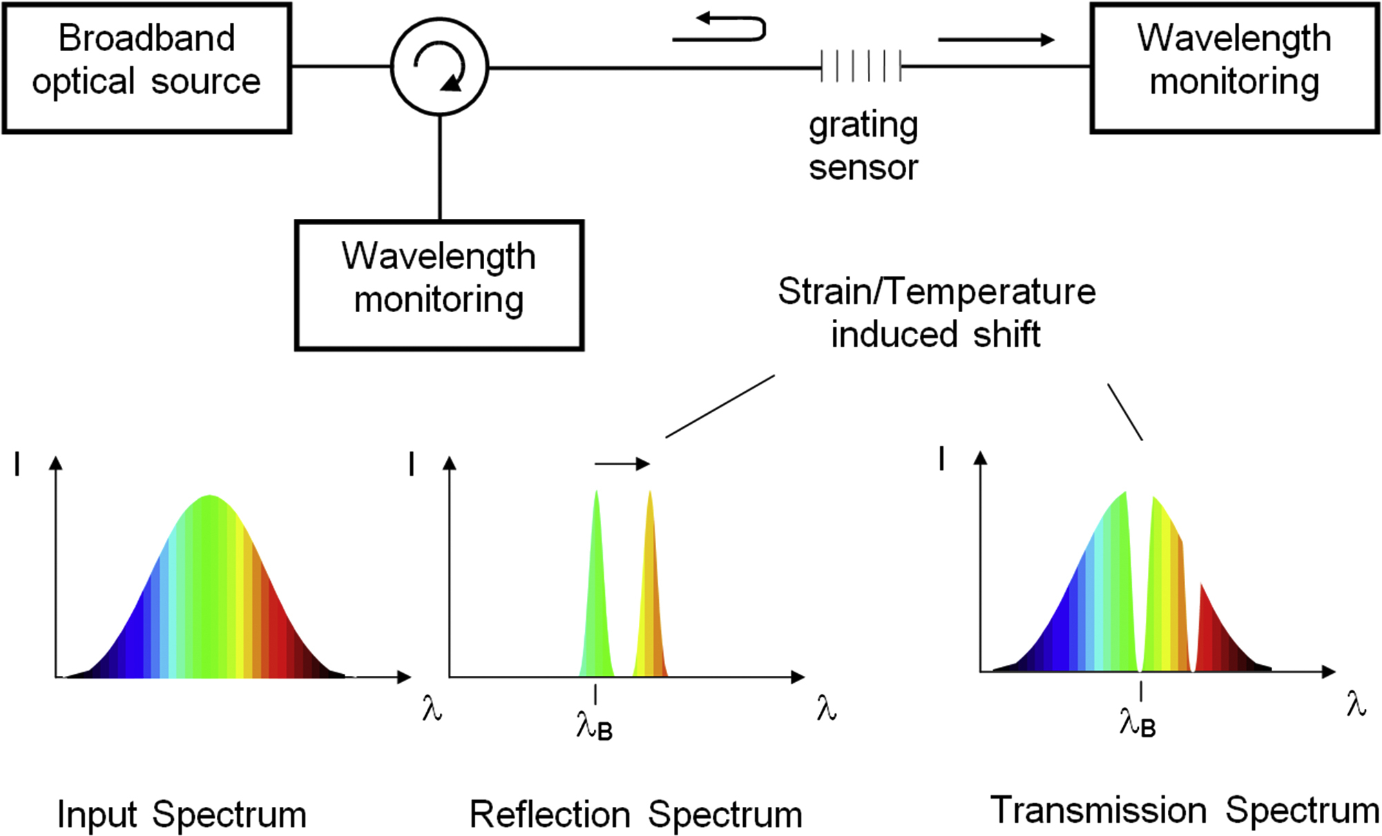
The FBG can also act as a temperature sensor whereby its sensitivity is mainly due to the thermooptic effect, i.e., temperature-induced change in the glass refractive index, and, to a lesser extent, to the thermal expansion coefficient of the fiber. Thus, λB shifts by an amount ΔλB in response to strain ε and temperature change ΔT by [3]
where Pe is the strain-optic coefficient, αs and αf are the thermal expansion coefficients of any fiber bonding material and of the fiber itself, respectively, and ζ is the thermooptic coefficient. Because FBGs can be written to have different resonant wavelengths, they can be multiplexed into a sensor web where different stresses or temperatures can be measured at different locations along the optical fiber length. Commercially available FBG interrogators that monitor spectral shifts in the Bragg resonance due to temperature and strain have spectral resolutions in the telecom band on the order of 1 pm. Direct monitoring of shifts in λB results in minimum detectable strains of ∼1 με/ rms at constant temperature and minimum temperature variations of 0.1°C in the absence of strain [3]. For applications at modest temperatures (<300°C), Bragg grating sensors have been used in civil structures, aircraft, naval ships, oil pipelines, etc., as “smart skin” sensor webs to measure “in situ” temperature and stress of these structures. At more extreme temperatures (>450°C) type I gratings are unsuitable as sensing elements because most of the refractive index change is annealed out at these temperatures.
6.4. Femtosecond Laser-Induced Bragg Gratings
In 2003, we demonstrated that Bragg gratings made with femtosecond pulse duration infrared (fs-IR) laser radiation could induce grating index modulations in optical fibers that were stable at much higher temperatures [17]. The nonlinear multiphoton mechanisms for this laser-induced index change are significantly different from the UV photosensitivity mechanism that is dependent upon color-center formation. FBGs written using fs-IR lasers have different properties and offer many advantages over conventional UV laser–written gratings. The most important advantage is that the process is not limited to silica-based UV-photosensitive fibers. Grating structures can be inscribed in any waveguide material that is transmissive to low-signal IR radiation regardless of its photosensitivity to UV light [18]. Examples include pure silica core, borosilicate, phosphate, fluoride (ZBLAN), chalcogenide, bismuth oxide, and aluminosilicate glass fibers as well as crystalline sapphire, YAG, and LiNbO3 fibers and waveguides. Because of the nonlinearity of the index change mechanisms, grating structures can be fabricated that are stable up to the glass transition temperature of the host waveguide material, making these gratings ideally suited to high-temperature/harsh environment applications.
6.4.1. Femtosecond Laser-Induced Index Change Mechanisms
The ultrahigh peak intensity radiation generated by fs-IR laser systems has been used to induce large index changes in bulk glasses for the fabrication of embedded waveguides [19]. Peak laser beam intensities over 1013 W/cm2 create strong nonlinear absorption that results in highly localized energy deposition within the focal volume of the bulk material during the laser pulse. This energy deposition is followed, after several picoseconds, by transfer of the laser-excited electron energy to the lattice of the bulk material, leading to permanent material modification. The complete physical model for this laser–material interaction is not completely understood; however, the mechanism for induced index change probably results from nonlinear processes that can be described in the following sequence: seed electrons are produced within the material through thermal excitation or nonlinear photoionization, which subsequently produces a free electron plasma that is sustained through multiphoton or tunneling ionization as well as avalanche ionization during the laser pulse. Energy transfer from the plasma to the bulk material occurs after several picoseconds, resulting in modification to the material such as compaction and/or defect formation, localized melting, or void formation, depending on the intensity of the laser pulse.
6.4.1.1. Free Electron Plasma Formation
For transparent dielectric materials, there is no linear absorption of incident light, i.e., the energy of individual photons is insufficient to jump the bandgap and be linearly absorbed by the material. Valence electrons are instead transferred to the conduction band via nonlinear multiphoton ionization and/or tunneling photoionization. The relative contributions of these processes to free electron generation depend on laser wavelength and intensity [20,21]. Avalanche photoionization is another process also at play, which depends linearly on the laser intensity.
In a sufficiently intense radiation field, multiple photons can be simultaneously absorbed by an electron in the valence band, resulting in its transition to the conduction band if the combined photonic energy absorbed is greater than the bandgap of the material (see Fig. 6.3A). At even higher intensities the band structure and potential barrier between valence and conduction bands of the material can be distorted, leading to nonlinear ionization via tunneling. Once in the conduction band, these electrons can further absorb incident laser light through free carrier absorption (see Fig. 6.3B). The accelerated electrons can then impact ionize bound electrons in the surrounding material, which give rise to even more free electrons that undergo free carrier absorption and impact ionize even more bound electrons. This process repeats itself as long as the laser field is sufficiently intense, generating an electron avalanche.
Avalanche ionization requires that a sufficient quantity of seed electrons be present in the conduction band. These seed electrons can arise from thermally excited impurity or defect states or from direct multiphoton and/or tunneling ionization. For longer laser pulse durations (>10 ps), the generation of seed electrons for avalanche ionization mostly arises from random thermally excited impurity states resulting in a nondeterministic fluence threshold (energy/unit area) for material modification that is dependent on the square root of the pulse duration [21]. For subpicosecond laser pulses, trigger electrons for the avalanche ionization process are created through direct multiphoton ionization processes, not random thermal excitation, causing a deterministic threshold fluence for material modification. Conduction band electrons are heated much more quickly than energy can be transferred to the lattice. The electron density in the conduction band then grows through avalanche ionization until the plasma frequency approaches the frequency of the incident laser light, at which point the plasma becomes strongly absorbing [20]. This electron density, known as the critical plasma density for free electrons, is on the order of 1021 cm−3 for near-IR laser light. The plasma will continue to strongly absorb for the duration of the laser pulse. At higher plasma densities, a significant portion of the laser energy can be reflected. It is usually assumed that optical breakdown occurs when this critical density is reached. For glasses, optical breakdown is achieved with intensities on the order of 1014 W/cm2.
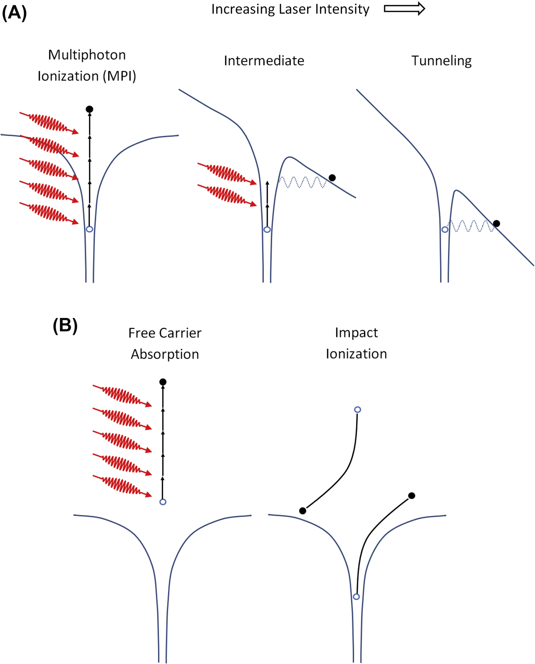
Figure 6.3 Schematic of free electron plasma formation with high-intensity pulses where (A) multiphoton and tunneling ionization generates free electrons that (B) absorb radiation and impact ionize surrounding material, resulting in avalanche ionization.
For subpicosecond pulses there is no significant transfer of absorbed laser energy to the lattice until well after the laser pulse is terminated. A shock-like deposition of energy occurs on a time scale much more rapid than the thermal diffusion time of the material, resulting in ablation of the material, if the laser light is focused on the surface, or permanent structural change if the laser light is focused in the bulk. This is somewhat different from the type II UV laser–induced damage process in fibers discussed in Section 6.2 where energy transfer to the lattice occurs while energy is still being fed into the plasma by the nanosecond pulse. The lattice is then catastrophically disrupted beyond the high-intensity portions of the radiation.
6.4.1.2. Regimes of Induced Index Change
It is agreed that for femtosecond pulses, multiphoton ionization followed by avalanche ionization forms a free electron plasma. However, once the electrons have transferred their energy to the lattice, the physical mechanisms for material modification are not fully understood. There are three types of material modification that have been identified that depend on the incident intensity: a smooth refractive index change similar to the UV laser–induced type I index change in Ge-doped fibers [22], a form of birefringence [23], and microexplosions leading to empty voids [24].
6.4.1.2.1. Type I or Smooth Refractive Index Change
When 800-nm femtosecond pulse duration laser light having intensities below the material-dependent ionization threshold Ith is used, smooth refractive index changes can be induced in bulk silica that could be erased through annealing [22]. In fused silica, this index change is associated with an increase in material density. Micro-Raman spectroscopy has confirmed an increase in the concentration of three- and four-member rings in the silica structure exposed to high-intensity fs-IR radiation, indicating a densification of the glass [25]. This index change is also associated with the presence of self-trapped exciton defects and a blue emission at 475 nm during laser exposure at inscription intensities of ∼5 × 10¹³ W/cm2 [26]. In bulk Ge-doped silica, the formation of oxygen-deficient (GeE′, SiE′) and nonbridging oxygen hole center defects was observed during fs-IR laser irradiation of Ge-doped glass [19].
When applied to FBG inscription in standard optical fibers with femtosecond pulse-duration 800-nm radiation, it was shown that generation of the smooth or type I refractive index change scaled with the fifth power of the inscription intensity, indicating a five-photon absorption process [27]. This scaling dependence between energy for a given femtosecond pulse duration and induced index change is shown in Fig. 6.4. Similar color center defects play an important role in UV laser–photoinduced type I index change associated with standard FBGs. It is likely that densification and color centers also play an important role in the smooth index change regime associated with femtosecond laser exposure although the contribution of each mechanism will vary depending on the glass composition. It was found that by hydrogen loading standard telecom Ge-doped optical fibers, the threshold intensity for FBG formation was reduced by a factor of 3 in the type I regime compared to pure silica core fibers, which were not affected by the hydrogen loading process [28]. This result implies that methods for induced index change enhancement while using lower intensity longer pulse duration UV systems (such as H2-loading, high-Ge-content cores, etc.) can also be exploited with high-intensity IR systems.

Figure 6.4 (A) Growth of the index modulation as a function of time and pulse energy. (B) Scaling behavior of the Δn growth rate as a function of energy. From Smelser CW, Mihailov SJ, Grobnic D. Formation of Type I-IR and Type II-IR gratings with an ultrafast IR laser and a phase mask. Optics Express 2005;13(14):5377–86.
6.4.1.2.2. Birefringent Refractive Index Change (Type II)
Above the Ith, where the laser–material interaction is accompanied by white light generation resulting from multiphoton ionization and plasma formation [22], laser-induced dielectric breakdown of the material causes an index change that is permanent at temperatures approaching the glass transition temperature of the material. At pulse durations longer than 10 ps, the dielectric breakdown results in disruption and laser damage of the material. For subpicosecond pulses at intensities on the order of 1014 W/cm2, the laser-induced dielectric breakdown results in a refractive index change that was found to be birefringent [23]. This birefringence is attributed to the formation of periodic nanogratings caused by the interference in the laser field with the induced electron plasma wave [29]. The orientation of the nanogratings was perpendicular to the polarization of the inscription laser [30].
6.4.1.2.3. Void Formation
At intensities greater than 1014 W/cm2, microexplosions within the bulk glass result in microvoids [24]. Pressures greater than Young's modulus are generated in the focal volume, creating a shock wave after the electrons have transferred their energy to the ions (∼10 ps) [31]. Taking conservation of mass into consideration, the shock wave leaves behind a microvoid or rarefied material surrounded by more compact, higher density material of higher refractive index.
6.4.2. Techniques for Fiber Bragg Grating Inscription With Femtosecond Lasers
6.4.2.1. Bulk Interferometers
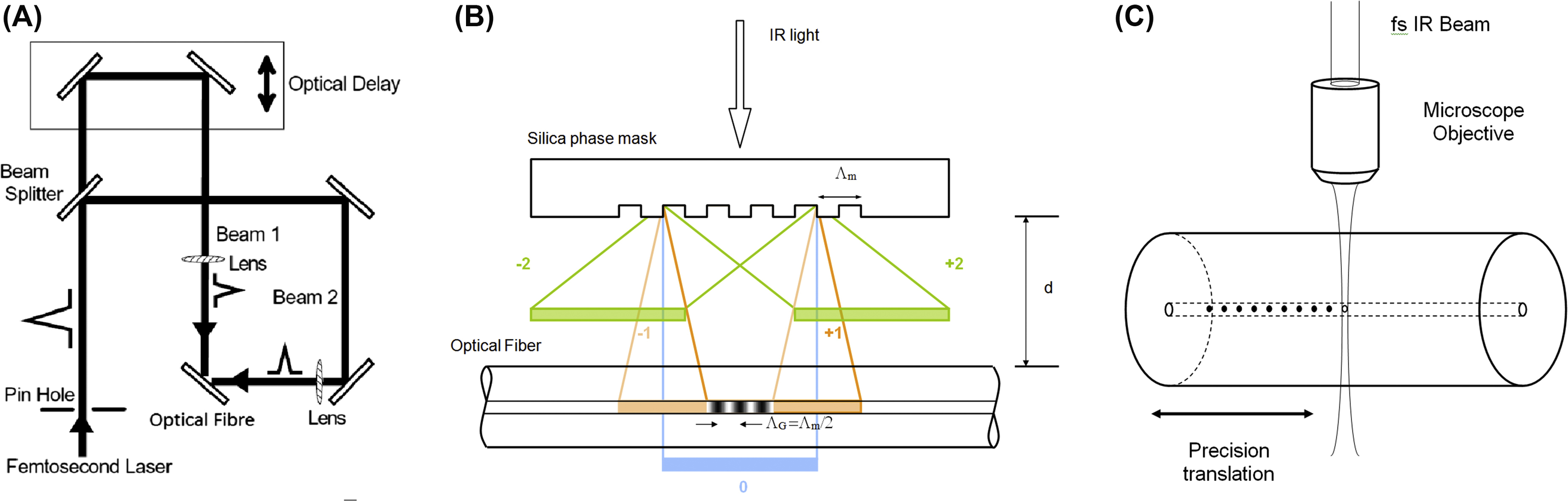
Analogous to the development of UV laser inscription techniques for FBGs [2], there are three main approaches to inscribing Bragg gratings with fs-IR laser sources. The first approach to be demonstrated utilizes a bulk interferometer to produce periodic index change structures in bulk silica [31a](see Fig. 6.5A). Although never explicitly applied to grating inscription in fibers, this approach has the advantage of being able to generate a wide variety of grating periods depending on the incident angles of the overlapped femtosecond beams. Path lengths for the two interfering beams need to match to within the spatial envelopes of the propagating femtosecond pulses, which for a 100-fs pulse corresponds to a spatial envelope of the electromagnetic field of only 30 μm. From a practical point of view, however, it is extremely difficult to match path lengths in a bulk interferometer to within 30 μm, especially within an industrial setting.
A variation of the bulk interferometric approach is that of the Talbot interferometer, whereby the beam splitter is replaced by a phase mask that acts as a beam splitter [32]. This approach relaxes some of the alignment tolerances needed to overlap femtosecond laser pulse beams and has been demonstrated using 262-nm 350-fs pulses for FBG inscription [33].
6.4.2.2. Phase Mask
For traditional UV laser–induced gratings, the phase mask approach to grating inscription is ideal from an industrial perspective in that the path lengths of the beams experiencing interference (±1 order) are automatically matched. This is especially important when low spatial coherence laser sources such as excimer lasers are used to generate the interference pattern [34]. In such cases path lengths need to be matched to within the spatial coherence of the excimer source, which is on the order of ∼100 μm. For femtosecond irradiation similar path-length matching (30 μm for a 100-fs pulse) is needed.
The first successful approach to fabricating FBGs with femtosecond irradiation was demonstrated using a specialty phase mask that was precision etched to maximize coupling of the incident IR laser radiation into the ±1 order [17,35]. The phase mask automatically matched path lengths of the generated orders when aligned at normal incidence to the inscription beam to within the dimensions of the spatial envelope of the femtosecond pulses. The phase mask–generated sinusoidal interference field results in a nonsinusoidal modulated FBG structure in the fiber owing to the nonlinear induced index change processes discussed in Section 6.4.1. Such nonsinusoidal modulated gratings produce higher order filter responses beyond the fundamental Bragg resonance given in Eq. (6.1), namely,:
where m is the harmonic order number [36]. Phase masks can then be designed where Fourier components of the index modulation will be resonant at wavelengths of interest [37]. An advantage to using masks that produce higher order resonances, say the telecom C-band, is that the grating pitch ΛG is much larger than what the grating pitch would be to generate the fundamental Bragg resonance. For gratings resonance in the telecom band at 1550 nm, the pitch of the structure itself is ∼535 nm, below the resolution limit of most optical microscopes. A higher order grating pitch is easily visualized under an optical microscope. The disadvantage of using gratings with higher order resonances is that the Fourier component of the index modulation that dominates the index modulation profile is usually at the fundamental resonance. Therefore the fundamental Bragg resonance is the one that has the highest reflectivity.
6.4.2.2.1. Phase Mask Order Walk-Off
Ultrafast pulses interact differently with phase masks compared to nanosecond pulses or continuous wave sources. As the diffracted pulses produced by the mask propagate away from the mask surface, the propagation distance of each pulse, when projected onto the optical axis normal to the mask, appears different, as is shown in Fig. 6.5B. The diffracted pulse envelopes have different arrival times at a given distance d normal to the mask. For sufficiently large d, the diffracted order pairs (0, ±1, ±2, etc.) no longer overlap, resulting in a diffracted order walk-off effect. For example, if we consider Λm = 3.213 μm and a 125-fs pulse, where Λm is the pitch of the mask, the spatial separation of the ±1 order from the 0 and ±2 orders would occur at fiber–mask distances d > 1.3 mm for a 100-fs pulse. As the induced index change using fs-IR radiation is highly nonlinear and highly localized within the target material, small d values (i.e., near the mask) produce multiple-order complex interference field patterns within the waveguide [38]. The resulting grating pitch ΛG is the same as that of the mask Λm. For large d values, the two-beam interference fringe patterns, caused by the diffracted order walk-off effect, can be produced inside the waveguide with only the high-energy ±1 orders from the mask [39]. Because the process for induced index change is highly nonlinear, the intensity of the 0 order is too low to induce an index change on its own and does not contribute to the final grating pattern. The clear advantage of the walk-off effect is that for short pulses, the phase mask need not be zero-order suppressed to produce a pure two-beam interference pattern. When the order walk is employed, the resulting grating period from interference of the ±1 orders alone is ΛG = Λm/2, similar to that for a phase mask used in the standard UV laser FBG inscription process.
6.4.2.3. Point-by-Point Grating Inscription
The final approach to fs-IR laser-induced FBGs utilizes a “point-by-point” (PbP) writing technique whereby single pulses from the fs-IR laser are focused within the core region of the optical fiber using a powerful microscope objective (see Fig. 6.5C). Highly localized changes to the refractive index are generated with each pulse to create each plane of the fiber grating. Subsequent planes are made in a step-and-repeat fashion by translating the beam using sophisticated high-resolution mechanical translation stages [40]. As the index change results from intensities greater than Ith, the grating structure consists of material compaction surrounding void formation at each grating plane [41] The resulting structure has thermal stability similar to that of type II UV gratings [42] and to gratings written in the type II regime with the fs-IR laser and the phase mask [27].
6.5. Applications of Femtosecond Laser-Induced Fiber Bragg Gratings for Sensing
Existing UV laser–based FBG sensors have been widely used for distributed strain, temperature, and pressure sensing. FBG sensor arrays have been deployed for static and dynamic strain measurement for structural health monitoring in aerospace and civil applications. Temperature- and pressure-based FBG sensors have been used, for example, in the energy sector for downhole oil well and reservoir monitoring where harsh environments of 20 kpsi pressures and 185°C are commonplace [43]. There is, however, increased demand for fiber optic sensing in harsh environments. Continuing in the energy sector, new techniques of unconventional oil extraction based on thermal recovery, such as steam-assisted gravity drainage (SAGD), cyclic steam stimulation, or toe-to-heel air injection, will require temperature/pressure sensors that can operate at temperatures up to 600°C [44]. For natural gas turbines or entrained coal gasifier monitoring, sensors need to operate at temperatures above 1600°C [45]. However, in these higher temperature harsh environments, standard UV laser–induced gratings quickly anneal out and disappear.
For applications in the oil and gas sector, for example, fiber-optic sensors are hampered by fiber losses resulting from ingress of hydrogen gas that occurs at the elevated temperatures within the downhole environment. This is especially true for standard Ge-doped telecom fibers. Employing pure silica core fibers that do not suffer from hydrogen-induced attenuation can mitigate these effects [44]; however, FBG-based distributed sensing arrays are extremely difficult to produce in pure silica core fiber using conventional UV laser–based inscription. The approach of using high photonic energy 193-nm radiation in pure silica core fibers [46] requires very lengthy exposure times, which degrade fiber reliability and are not practical from a production standpoint. Using the fs-IR approach, high Δn FBGs can be easily written in pure silica optical fibers that are resistant to hydrogen-induced loss [35]. The use of such fibers is essential for improving sensor array performance to monitor, for example, SAGD in the oil and gas industry.
6.5.1. High Temperature
When inscribed with intensities above Ith, FBGs written using either a phase mask or the PbP method can be made stable up to the glass transition temperature of the optical fiber. Such gratings are ideally suited to applications in harsh environments such as within power plants, turbines, and combustion systems and in aerospace applications. Attributes of FBGs written with fs-IR radiation and a phase mask above Ith in both UV-photosensitive Ge-doped SMF-28 from Corning and non-UV-photosensitive pure silica core (fluorine-doped silica clad) fibers were studied over a longer term [47]. Bragg gratings with higher order resonances and large index modulations were inscribed in both fiber types, which were then heated to 1000°C in 100°C increments at 1-h intervals within a tube furnace. In these experiments, the FBGs were loosely placed to avoid the application of external stresses. The change in index modulation with this isochronal annealing is presented in Fig. 6.6A, where type I and type II gratings were annealed alongside a standard UV laser–induced grating. Both UV and fs-IR type I gratings are observed to anneal during the process, with complete erasure of the UV grating observed. An increase in Δn of the type II grating was observed, as noted by the slight elevation in grating reflectivity. Once 1000°C was reached, the temperature was maintained at 1000°C for 150 h while the type II FBG transmission spectra were monitored (see Fig. 6.6B). There was no noticeable degradation of the grating strength for the duration of the test and the grating maintained an index modulation of Δn = 1.7 × 10⁻³. The increase in the type II grating reflectivity during the isochronal annealing stage of the experiments is likely to be a result of the two kinds of index change being written simultaneously during the grating preparation. The peaks of the complex interference pattern are sufficiently intense to ionize the glass in the fiber, producing an index change that is durable with temperature. In the valleys of the interference pattern, the intensity is below the type II threshold; however, some type I index change is generated. As the device is annealed, the permanent type II index change remains, while the annealable type I index change is erased, resulting in a higher Δn contrast. The temperature of the FBG was then increased and kept at 1050°C for 100 h, during which the Δn decreased slightly from 1.7 × 10⁻³ to 1.6 × 10⁻³. Spectra taken initially at room temperature and after 100 h at 1050°C are shown in the inset of Fig. 6.6B. A drift of the Bragg resonance to longer wavelengths of 0.2 nm was detected at the end of the experiment. When the fiber is preannealed at high temperatures to relax residual stresses, type II fs-IR FBGs are operable up to 1200°C [50] without this observed thermal drift.
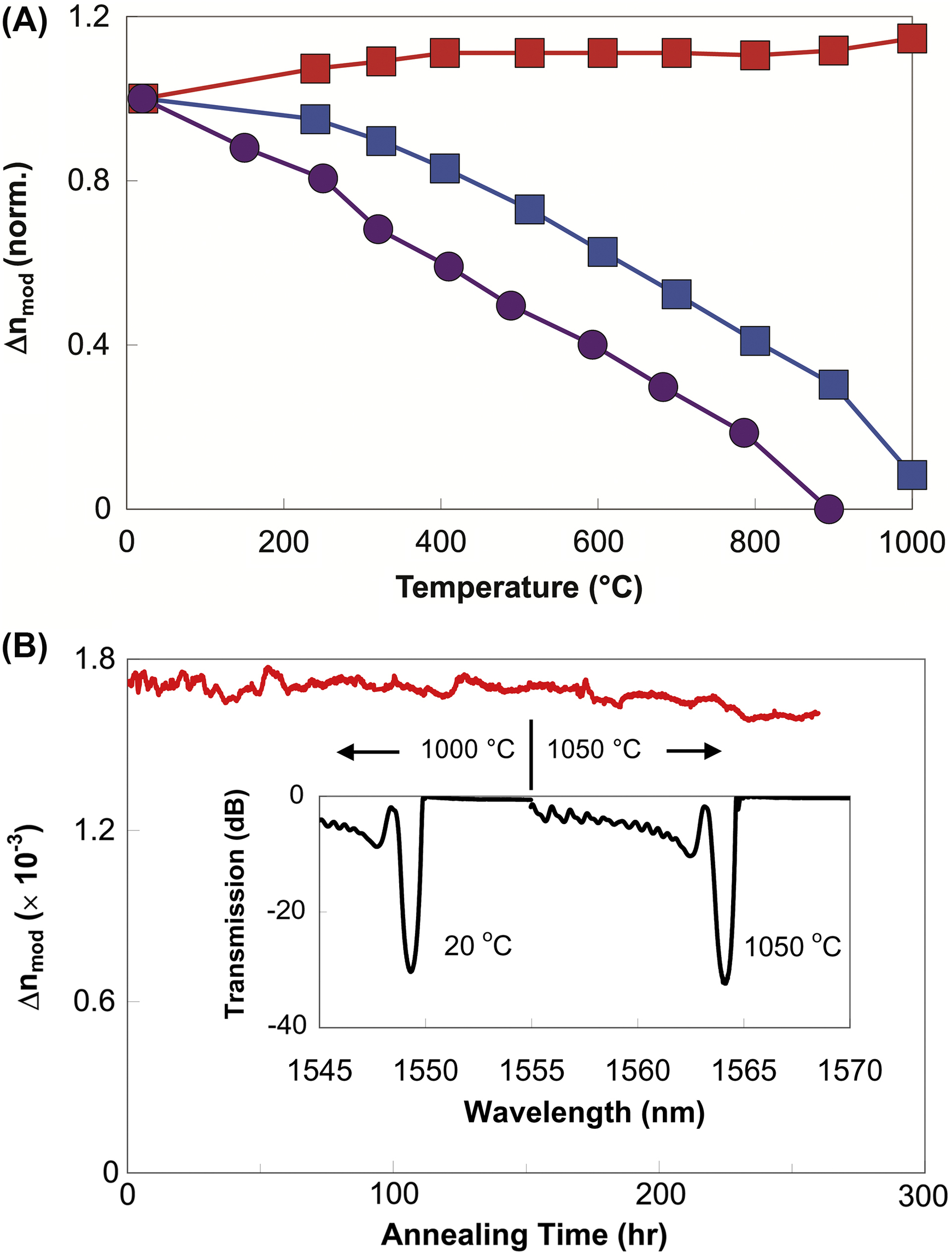
Figure 6.6 (A) Short-term annealing of type II-IR [red (darker gray in print versions)]), type I-IR [blue (dark gray in print versions)], and type I-UV [violet (light gray in print versions)] gratings held at each temperature for 1 h. (B) Grating reflectivity expressed as its index modulation (Δn) for a thermally stable grating [red (light gray in print versions)] as a function of time. (Inset) Grating spectrum as a function of temperature.
For operation in a high-temperature environment, an important issue for any silica-based fiber optic sensor is that of sensor packaging. At temperatures close to or above 1000°C in air, unpackaged standard silica single-mode fibers lose almost all of their mechanical strength. While the fibers themselves survive hundreds of hours at 1000°C when left untouched, any subsequent handling of the fiber after the test is not possible as the fiber becomes extremely brittle [47]. Obviously optical fibers experience severe mechanical degradation when tested in oxidizing atmospheres at high temperature.
Protecting the fiber from exposure to oxygen at high temperature could be achieved by using a suitable package that itself survives the high temperature. The most obvious choice would be a coating on the fiber that is applied after the gratings are written or by writing through the existing protective coating. Metallic coatings are preferred for higher temperature applications, with gold coatings rated for the highest temperature of operation of 700°C; however, this rating is not suitable for temperatures close to 1000°C [51]. Stainless steel tubing or ceramic alumina tubing is a packaging option; however, these types of tubing are less forgiving when integrated into composite structures or confined spaces.
Using the fs-IR laser/phase mask approach, a type II grating was made in a fiber cane, which is a single-mode optical fiber with a 400-μm cladding [52]. To test the mechanical strength after long-term annealing, the FBG written into the fiber cane was placed in a tube furnace in air set at 1020°C for 150 h, after which the temperature was slowly ramped down to room temperature. Room temperature spectra taken before and after the 150 h of annealing are shown in Fig. 6.7. The 400-μm-clad fiber maintained enough mechanical integrity to be easily handled even after the fiber was removed from the furnace. The FBG was subsequently proof tested by suspending the fiber in a vertical position from a support and then applying weights to the fiber in 50-g increments with a 60-s delay time before the application of each additional weight. The fiber was tested up to 500 g of force, which for the 400-μm diameter corresponds to ∼39 MPa maximum stress. The pristine fiber was proof tested by the manufacturer to 690 MPa. Although the fiber is more rigid than 125-μm-diameter single-mode fiber, it can normally accept bending radii of less than 10 cm, making it suitable for the majority of sensing applications.

Figure 6.7 Initial and final room temperature spectra of thermally stable fiber Bragg gratings inscribed in large-diameter fiber cane fibers. The final spectrum was taken after 1 week at 1020°C.
For temperatures >1200°C, silica-based optical fibers are no longer appropriate. The most successful optical fiber used for high-temperature sensing applications is the single-crystal sapphire fiber that has a glass transition temperature of ∼2030°C [53]. Unlike conventional single-mode optical fibers, sapphire fibers are made in the form of a single rod absent a cladding layer, which makes the sapphire waveguide highly multimode and sensitive to bending losses and mode conversion. With fiber diameters commercially available, beam propagation within the fiber is highly multimode at the 1550-nm telecommunication wavelengths. An example of available fiber diameters is shown in Fig. 6.8A and B. As of this writing, sapphire fiber sensors are mostly based on Fabry–Perot structures within the fiber, producing a broadband interferometric signal that varies with temperature [45]. Such devices are used effectively as point sensors; however, they are more difficult to use for distributed sensing, i.e., measuring at multiple points along the fiber.

Figure 6.8 Cross sections of commercially available (A) 125-μm- and (B) 60-μm-diameter sapphire fiber are shown. The grating structure inscribed in a 150-μm-diameter fiber is shown in (C); the corresponding multimode reflection response is shown by the red (light gray in print versions) trace in (D). When the single-mode field expander shown in (E) is used, the single-mode reflection spectrum shown in green (dark gray in print versions) in (D) is obtained. SFBG, sapphire fiber Bragg grating; SMF, single-mode fiber.
Femtosecond laser–inscribed FBGs in sapphire fiber (SFBGs) have been demonstrated only using the phase mask approach [54]. Although it is possible to inscribe grating planes rather than microvoids using the PbP method [55,56], it is very time consuming, especially considering that a volume grating across the entire cross section of the multimode sapphire fiber (typically 150 μm diameter) would be needed. Volume Bragg gratings are easily inscribed across the entire sapphire fiber cross section with the phase mask approach.
SFBGs are naturally multimode devices producing a reflection response that is not as sensitive to temperature and strain as the spectrally narrow single-mode FBG sensors. The red (or light gray) trace in Fig. 6.8D presents an example of a typical multimode reflection response from an SFBG sensor when interrogated with a multimode coupler and white light source. The multimode reflection spectrum observed with the retroreflective SFBGs is characterized by a large bandwidth having a complicated structure that consists of a superposition of different modes reflected by the grating. Although numerical techniques and spectral averaging have been developed to improve the sensitivity of the measurement of the SFBG shift as a function of temperature [57], it is preferable to produce a narrowband single-mode response, as it increases the sensitivity of the spectral response to changes in temperature and strain. To arrive at a single-mode response from the multimode SFBGs, they can be probed by using an adiabatic fiber taper to expand the ∼10-μm diameter single mode into a fundamental mode approaching the diameter of the sapphire fiber (as shown in Fig. 6.8E) [48]. The fundamental guided mode of the sapphire waveguide is excited, producing a single-mode reflection response [green (or dark gray) trace Fig. 6.8D]. In this fashion, single-mode reflection responses compatible with existing FBG sensor array interrogators can be generated.
SFBGs exhibit no degradation of the grating strength at high temperatures up to 1850°C [58]. The SFBG has definite advantages over other sapphire fiber sensors that rely on Fabry–Perot etalons at the fiber tip. Unlike Fabry–Perot sapphire sensors, SFBG sensors with their discrete resonant wavelength could potentially be used as distributed optical sensor arrays up to 2000°C.
Gas turbine monitoring is an example in which high-temperature optical sensing would be useful. Accurate measurement of hot gas working temperatures within a turbine is the critical control parameter that is essential for safe, reliable, efficient, and cost-effective operation of the gas turbine. Inhomogeneous combustion can lead to overheating and considerable damage to turbine blades; however, accurate measurements of the blades and vanes within a gas turbine are very difficult [59]. By probing gas temperatures in the turbine exhaust path, temperature distributions within the combustion chamber can be evaluated. Several types of high-temperature FBG sensors have been evaluated for monitoring of hot gas turbine components by placing them on a heat shield tile mounted on the side of the combustion chamber exhaust [60]. Several of the gratings were erased at various temperatures depending on the fabrication technique used: UV laser–induced draw tower gratings annealed out at 250°C; weak and strong excimer laser–induced type I gratings at 450°C and 700°C, respectively; and UV type II gratings at 900°C. Fs-IR laser–induced type II gratings and regenerated gratings were observed to have short-term stability at 1000°C; however, softening of the fused silica was observed to commence at 850°C, which resulted in a drift in the grating response. At 800°C, drift was observed. Only the fs-IR gratings were reported to have stable operation, even after a duration of several months at 800°C.
6.5.2. High Radiation
For nuclear applications, electronic transducers and gauges are often unsuitable in nuclear environments, especially when intense nuclear radiation is accompanied by elevated temperatures, chemical contamination, and high levels of electromagnetic interference. Neutron bombardment results in damaging effects to materials; for example, thermocouple output will drift under intense radiation as the two metals forming the thermocouple gradually transmute into different elements.
UV laser–inscribed FBG sensor arrays based on Ge-doped optical fibers have been demonstrated to be radiation tolerant in low-flux nuclear environments, even for extended periods of time [61]. However, in high-flux environments, Ge-doped optical fibers are susceptible to radiation-induced attenuation (RIA), which after a period of time will render the fibers opaque. The RIA process is similar to the defect formation mechanism that occurs during UV type I grating inscription in Ge-doped fibers. For reliable strain and temperature measurements it is therefore necessary to inscribe gratings in radiation-hardened fibers that are resistant to RIA, such as fibers with pure or fluorine-doped silica cores [62]. Because these fibers, by their design, are inherently non–UV photosensitive, standard UV laser grating writing techniques are ineffective. Gratings were easily inscribed in highly radiation hardened F-doped fibers [63] using the fs-IR approach with a phase mask, in both the type I and the type II regime [63a]. Very little change was observed in the spectral quality of the grating even after a dosage of γ−radiation of 100 kGy.
6.5.3. Multiparameter Sensing in Harsh Environments
For FBG sensors, the resonant Bragg wavelength of the grating, λB, is the primary sensing parameter that is monitored. Unfortunately it is often difficult to discriminate between different effects, for example, temperature and strain, with a single FBG because different effects can impact simultaneously on λB. Often another Bragg grating that is isolated from one of the effects is used for each of the parameters involved in a particular case, but this procedure will result in a very complicated sensing configuration. To avoid the multifiber solution to multiparameter sensing problems, a variety of other alternatives have been used. Techniques to discriminate sensing parameters include double superposed grating structures with different λB [64], FBGs in fiber with dissimilar diameters [65], utilization of the second-order diffraction from a saturated first-order 1550-nm grating [66], FBGs in birefringent fibers [67], etc. These techniques were developed mainly for the particular case of strain and temperature discrimination. A comprehensive summary of these methods is presented in a review paper [68].
For high-temperature environments below 1000°C, type II gratings in silica fibers can be effective multiparameter sensors. Whether written with pulsed UV lasers or fs-IR lasers, the nonsinusoidal profile of the index modulation results in higher order resonances [35,69] as previously noted in Eq. (6.3). For a standard grating in low-wavelength cut-off telecommunication fibers, the grating pitch needed for a fundamental Bragg resonance at 1550 nm is 535.5 nm. The fabrication of an fs-IR laser–written type II grating with a pitch of ΛG = 4.184 μm, eight times longer than the needed fundamental pitch, produced six high-order resonances that were observable when viewing the transmission of the grating in the wavelength range from 1 to 1.8 μm [70]. The multiple-order resonances from the grating are depicted in Fig. 6.9. From Eq. (6.3), the order m of these resonances ranges from 7 to 12. The strain and temperature characterization of each resonance in this wavelength range was made and the temperature and the strain coefficients were evaluated. Wavelength shifts of the resonances due to temperature or strain were different for each grating order. In this way using a single grating, the cross-sensitivity of temperature and strain can be removed by monitoring the high-order resonances.

Figure 6.9 High-order spectra of a 4.28-μm pitched type II Bragg grating made in a 980-nm cut-off fiber.
An interesting approach to multiparameter sensing has been developed, which exploits the cladding mode resonances that are generated when a Bragg grating is tilted slightly (10 degrees) with respect to the fiber axis [71]. The cladding mode resonances are not core–cladding guided but cladding–air guided and can therefore interact with the environment surrounding the fiber. All the resonances, both core and cladding, have the same temperature dependence near room temperature in terms of wavelength shift; however, the strain dependence of high-order cladding modes differs from that of the core mode. Hence a dual temperature/axial strain sensor can be obtained from a single tilted grating. Because these gratings are based essentially on type I UV formation properties, they would not be effective in high-temperature environments. Extending this approach with the fs-IR laser inscription, tilted gratings were made with a phase mask and an 800-nm laser that act as a dual-parameter temperature and strain sensor up to 800°C [72].
By inscribing a grating with an fs-IR laser using a phase mask or the PbP technique in such a way that the index change is localized near the core–cladding interface of the fiber, it is possible to couple much of the guided mode into cladding modes that behave in a similar way to the cladding modes generated by a tilted grating [73,73a,74]. The type II grating planes or PbP consists of microvoid spot structures at the core–cladding interface that are thermally stable up to at least 1000°C. Such nontilted devices could therefore be used as multiparameter sensors in high-temperature environments.
Above 1200°C multiparameter optic sensors cannot be made with silica fibers. There are several instances in which measuring both temperature and strain in a high-temperature environment is important, for example, inside jet engines and turbines for electric power generation using natural gas. For these temperatures, SFBG sensors have been demonstrated for temperature measurements [48]. At very high temperatures (>1000°C) thermal blackbody radiation produces a strong signal background that will reduce the signal-to-noise ratio of a multimode Bragg grating reflection [75]. By exciting the fundamental mode of the sapphire waveguide, the single-mode grating reflection improves the signal-to-noise ratio. Monitoring of blackbody radiation with sapphire fibers is well known [53]. By taking advantage of the improved signal-to-noise ratio afforded by fundamental mode excitation of the SFBG and the known blackbody radiation spectrum as a function of temperature, a dual-parameter strain/temperature sensor in sapphire fiber was realized [76]. The signal level of thermal blackbody radiation was monitored as a temperature reference, to allow for the portion of the wavelength shift dependent on temperature to be decoupled from the strain.
6.5.4. High Pressure
When exposed to high pressures, type I FBGs undergo a negative wavelength shift that is proportional to the level of hydrostatic pressure [77]. The wavelength shift is modest and is on the order of −3 pm/MPa but was demonstrated to change in a linear fashion to pressures up to 10,000 psi (70 MPa). By using elastomer and polyurethane fiber coatings, the sensitivity of the gratings to pressure could be increased 20-fold [78]. More recently a carbon fiber–laminated composite structure was adhered to an FBG, which further enhanced its sensitivity by 3 orders of magnitude and was demonstrated at pressures up to 70 MPa [79]. In these cases, pressure measurements were conducted at or near room temperature.
If there is a requirement to measure high pressures as well as high temperatures simultaneously, then a multiparameter pressure/temperature sensor based on type I grating structures is undesirable at temperatures above a few hundred degrees Celsius. Using a side-hole fiber geometry, simultaneous measurements of high pressure and temperature were performed [80]. The birefringent nature of the fiber resulted in two polarization-dependent resonances of the type I Bragg grating. With increasing pressure within the side holes, a reduction in the separation of the polarization-dependent resonances was observed. Any changes in temperature were observed by identical wavelength shifts of both resonances.
Using the same kind of side-hole fiber geometry, thermally stable fs-IR laser–induced type II and regenerated gratings were inscribed in microstructured side-hole fiber to produce a sensor that could simultaneously monitor temperature and pressure in harsh environments [81]. These sensors were demonstrated to operate well in pressure ranges from 15 to 2400 psi (0.1–16.5 MPa) and at temperatures up to 800°C. This approach relies on the waveguide-induced birefringence of the grating response rather than the structural birefringence associated with type II index change discussed in Section 6.4.1.2.2.
As well, the core region of the fiber was located such that the guided mode would have some evanescent coupling into the side-hole region. With a grating in place, this structure could be used to measure the refractive index of materials or fluids within the side hole.
6.5.5. Chemical Sensing
There is a relatively large effort in sensing to use the capability of the evanescent field that can be created around an optical fiber to interact with the ambient environment to extract information about the magnitude of the ambient refractive index na and to transmit the resultant information as an optical signal. As of this writing, in-line fiber evanescent field devices that are transmissive in nature are based on biconical tapered fiber devices [82], long period gratings [83], and photonic crystal fiber [84]. To operate in a reflection mode, optical fiber–based refractometers need to incorporate a reflective element such as a Bragg grating. FBG-based refractometric devices require the guided mode to be converted to an evanescent field that can interact with the surrounding environment. Such evanescent fields have been created by polishing the fiber down to the core in the grating region [85] or chemically etching the fiber to a small diameter (10–20 μm) [86] or using a D-shape fiber [87]. These structures needed to be created in waveguides that were UV photosensitive.
When tapering silica-based fibers, the guided mode becomes cladding–air guided in the tapered region as opposed to core–cladding guided in the untampered single-mode fiber. Fiber claddings are typically silica, which is non–UV photosensitive. Using the femtosecond laser approach to grating inscription removes the constraint of UV photosensitivity and makes grating structures possible across the entire taper cross section of the nonphotosensitive silica fiber tapers. Examples of FBGs written in 50- and 30-μm diameter tapers are shown in Fig. 6.10A and B, respectively. Such gratings showed promise for refractometric and fluid-level applications [49].

By surrounding the taper FBG with a sensing layer, i.e., a material layer that will change either its mechanical or its optical properties when exposed to specific environmental conditions or analyte, a fiber-based chemical sensor can be realized (see Fig. 6.10C). Such as device was realized when an FBG was fabricated in a 50-μm diameter taper made from standard telecom fiber with a UV femtosecond system. The device was subsequently coated with palladium, making an effective H2 sensor [88]. Similarly femtosecond laser systems can be used to fabricate gratings in all-silica solid-core photonic crystal fibers either using phase masks [89,90] or by the PbP technique [91].
6.5.6. Passive Fiber Bragg Gratings for High-Sensitivity Strain Measurements
Improvements in FBG strain sensitivity beyond simple monitoring of changes in λB (∼1 με/ rms) were realized by interrogating the reflection edge of a narrowband FBG spectrum with a tunable narrow-linewidth laser resulting in a minimal detectable strain (MDS) of 45 pε/ [92]. By similarly interrogating the ultranarrow transmission passband of a π-phase-shifted Bragg grating structure with a mode-locked laser system, an MDS of 5 pε/ was obtained [93]. The introduction of a π-phase shift in the grating structure, i.e., removing a single grating plane in the center of the grating length, results in a structure that acts as a Fabry–Perot cavity, generating a narrow passband in the center of the reflection spectrum of the grating.
Interrogating the FBG at the transmission band edge where the group-velocity dispersion of the grating is maximized [94] results in slow-light effects that can be exploited interferometrically to produce high-sensitivity (sub-pε) FBG-based strain sensors [95]. The strain sensitivity of this approach is proportional to the index modulation Δn of the gratings while maintaining low insertion loss.
From a femtosecond laser FBG inscription perspective, it is straightforward to obtain large index changes >5 × 10⁻³ in the low insertion loss type I regime in silica-based waveguides. Femtosecond gratings were subsequently demonstrated using this slow-light approach to have MDS values of 280 fε/ when measured at a frequency of 23 kHz [96].
6.5.7. Active Sensing
Fiber laser cavities with intrinsic Bragg gratings, either in distributed feedback (DFB) or in distributed Bragg reflector (DBR) configurations, have been proven useful for applications in which high levels of sensor detection sensitivity are required. In the DFB configuration, the laser cavity is created by introducing a π-phase shift in the grating structure; the resulting structure acts as a laser resonator cavity. The DBR configuration comprises two FBGs with overlapping Bragg resonances and a given grating separation. Fiber laser acoustic sensors and in particular hydrophones and magnetic field detectors generally require high-resolution sensors with high signal-to-noise ratio accuracy. These active structures have achieved resolutions in strain measurements approaching tens of fε/ when interferometrically interrogated [97]. The cavities can be long, on the order of meters, meaning that the strain measurement is integrated over the laser cavity length. If such characteristics are needed in a high-temperature environment, then the Bragg reflectors that form the laser cavity need to withstand those harsh conditions without degradation in their reflectivity and hence degradation in the functionally of the fiber laser. A 25-cm-long laser cavity was built with regenerated gratings and was tested up to 750°C [98].
The type II gratings made with ultrafast radiation in silica-based fibers are prime candidates for cavity mirrors to be used in the moderate to high temperature range of 600°C–1000°C. The PbP technique was used to create a 3-cm-long laser cavity that was tested up to 600°C [99].
With the phase mask inscription method very short laser cavities (∼1 cm) were manufactured with high-reflectivity type II gratings in heavily doped active fibers: Er–Yb fiber with 475 dB/m loss at 975-nm wavelength and 26 dB/m loss at 1535-nm wavelength. The laser cavities were then tested up to 850°C [100]. When pumped with a 500-mW 980-nm laser diode, a 10% lasing efficiency was observed. The laser line wavelength shifted as a function of temperature as shown in Fig. 6.11. For this cavity architecture (two high-reflectivity uniform pitch gratings of 4 mm in length) nonuniformities in the heating caused the reflector mirror wavelengths to walk off each other above 850°C. A chirped high-reflector cavity mirror or a DFB configuration may be more favorable to avoid the nonfavorable effect of the temperature gradient.
6.5.8. Fiber Bragg Gratings for High Strain Measurements
For structural integrity monitoring using FBG sensor arrays, the capability to measure high strain levels is very desirable. Traditional FBG inscription with UV lasers requires the removal of the protective polymer coating to allow for the direct interaction of the laser radiation with the fiber material. This process, aside from being difficult and time consuming, usually results in significant weakening of the fiber if special precautions are not taken, increasing the possibility of fiber failure in field tests. As most polymer coatings usually are not transparent to UV radiation, attempts to write Bragg gratings through standard coatings with conventional methods have not been successful unless special UV-transmissive protective coatings were used [101].

Figure 6.11 The wavelength shift of the ~1 cm long fiber laser line emission with temperature. FBG, fiber Bragg grating.
The first demonstration of trans-jacket-inscribed FBGs utilizing fs-IR radiation through standard polymer coating was performed using the PbP method [102]. The resulting FBGs were thermally stable up to the glass transition temperature of the fiber. Using high-magnification microscope objectives, the PbP method is, by its nature, better suited to “through the coating inscription,” because large differential exposure intensities between the core and the coating are more easily achieved compared to the phase mask method.
Using the phase mask approach, first-order FBGs that resonated at the fundamental Bragg resonance were inscribed through standard acrylate coatings of high Ge-content bend-insensitive fibers and hydrogen-loaded SMF-28 fibers [103,104] as well as through polyimide coatings in high numerical aperture fibers [105]. Specialty fibers were used at that time, to decrease the radiation intensity required to induce refractive index change in the core, thus protecting the coating from being damaged by the laser beam. These gratings annealed at elevated temperatures, indicating that they were type I structures.
The phase mask method generally relies on longer focal length lenses to accommodate phase mask positioning between the targeted fiber/focusing lens and relax alignment restrictions. Shorter focal length lenses have shorter Rayleigh ranges and therefore greater variation in intensities experienced by the surface jacket and the fiber core. Unfortunately, a more converging lens, although creating a tighter focus, also results in an increase in geometrical aberrations. Cylindrical lenses previously used to focus the IR ultrafast radiation are affected by these aberration effects, producing larger than expected grating structures that are easily observed under the microscope. To create the large differential exposure between core and protective coating covering the cladding, a lens free of geometric aberrations is required.
In 2014, first-order type I FBGs were inscribed through acrylate and polyimide coatings of Ge-doped SMF-28 and pure silica core optical fibers using a fs-IR laser, an aspheric focusing lens, and a phase mask [106]. The aspheric cylindrical lenses allowed for a smaller spot size by reducing the geometrical aberrations and therefore produced higher laser intensities in the core of the fiber but below the threshold intensity needed to modifying the coating. The resulting type I gratings showed little degradation in their mechanical strength compared to the pristine fibers.
6.6. Conclusions
In this chapter, some of the developments in fabrication and application of femtosecond laser–induced FBGs for sensing have been presented along with some of the background theory on femtosecond laser–material interaction physics. For temperatures less than 1000°C, FBGs made in silica-based fibers through fs-IR laser exposure techniques based either on the phase mask approach or on the PbP approach can result in spectral responses that are stable at high temperatures. When exotic grating or fiber geometries are employed, multiparameter sensing from a single grating element can be realized. Gratings written in glasses such as pure silica or radiation-hardened fluoride-doped silica can be used for sensors in the oil and gas or nuclear industries, where losses in standard optical fibers due to hydrogen ingress or ionizing radiation can significantly reduce sensor lifetime. Chemically specific fiber optic sensors can be realized in tapered or photonic crystal fibers. Above 1200°C extreme temperature measurement with Bragg gratings is relegated to sapphire optical fibers. In the case of SFBGs, these robust devices are suitable for harsh combustion environments such as jet engines, coal gasification reactors, and natural gas turbines for electrical power generation.
..................Content has been hidden....................
You can't read the all page of ebook, please click here login for view all page.