
Previous Chapter
8. Fiber Optic Sensors in the Oil and Gas Industry: Current and Future Applications
9
Aerospace Applications of Optical Fiber Mechanical Sensors
Craig Lopatin Technion-Israel Institute of Technology, Haifa, Israel
Abstract
Owing to their light weight, immunity to electromagnetic interference, ease of multiplexing, lack of drift, and high level of maturity, optical fiber sensors would seem to be ideal for aerospace applications. However, the aerospace industry has been slow in adopting this technology, and this review suggests many of the reasons for this. One possible factor is that optical fiber sensors are often developed with insufficient input from the end user community, such as experts in nondestructive testing, structural engineering, and business considerations of fleet managers. While it has been shown that optical fiber sensors can detect defects in both metal and composite components, the ability to quantify the “probability of detection” is often difficult, although this is an important value for aircraft operators. Perhaps the most promising near-term applications for optical fiber sensors can be found in shape sensing for large space structures, such as antennae and solar sails.
Keywords
Aerospace; Bragg gratings; Composites; Defect detection; Distributed sensing; Helicopter blade monitoring; Optical fiber sensors; Service life; Shape sensing; Structural health monitoring; Vibration monitoring
9.1. Introduction and Background
Owing to their light weight, immunity to electromagnetic interference, ease of multiplexing, and other attractive characteristics and, not least, the vast amount of research in, and high level of maturity of, the technology, optical fiber sensors would seem to be ideal for aerospace applications, particularly for damage detection. However, as will be shown in the following, acceptance by the aerospace industry of this technology has been slow, and an important goal of this review is to suggest many of the reasons for this. Before going into details, it may be useful to provide some perspective from the end user community, and a valuable source of information can be found in a series of papers from a NATO workshop devoted to nondestructive inspection (NDI) methods for aircraft, and in particular, the paper by LaRiviere [1]. A key point made by the authors (from Boeing) is that, “when expertise from these three disciplines is integrated during the NDI procedure development phase, the result is a reliable NDI system that will continue to maintain a safe fleet.” The three disciplines referred to are structural engineering, NDI, and knowledge of airline customer requirements.
With this perspective in mind, it is sobering to note that the research groups most involved with development of optical fiber sensor methods are often made up of (or at least lead by) optical scientists/engineers, who do not generally have an expertise, for example, in composite fracture mechanics, although this expertise is necessary to cross the bridge from strain measurements on damaged composite structures to relevant lifetime/allowable load predictions of most interest to the final user. While command of, and improvements on, sensor technology is certainly required, too often, in this reviewer's opinion, the desire to push the sensor technology takes on more importance than a focus on the end goal, which is to be able not only to detect defects, but also to assess to what extent a defect affects future service life.
The LaRiviere paper also lists several quantitative requirements, currently met by NDI methods, that need to be satisfied to be accepted as possible replacements for current methods. For example, the current estimated minimum detectible crack size near holes in aluminum and titanium plates is 0.8 mm (detectible with high-frequency eddy current), and an interplay delamination in composites can be detected if it reaches 10 mm in diameter. These values can be used to evaluate the feasibility of optical fiber sensors being able to provide such spatial resolution.
In another paper in this collection [2], the authors make the important observation that, although since the Aloha Airlines accident (1988) the Federal Aviation Administration has sponsored several development efforts to detect corrosion, none of these efforts have been adopted by the industry. Several reasons are provided: detection of corrosion being considered an economic and not a safety issue, lack of a clear cost–benefit study showing the advantages of the new methods, and, not least, the lack of a rigorously validated probability-of-detection approach. Clearly, there is a lesson here for developers of optical fiber sensors who would like their technology to be accepted by the industry.
In addition to these general observations, there are also some specific reasons for the slow acceptance of optical fiber sensors by the aerospace community. One is technical: the vast majority of optical fiber sensing methods are passive, in contrast to active sensing methods used in conventional nondestructive evaluation (NDE). For example, relying solely on optical fiber Bragg grating sensing, and other forms of distributed strain sensing, to detect and quantify damage is difficult. On the other hand, NDE methods, such as ultrasound and eddy current, which are based on providing an input stimulus (sound and electromagnetic pulse, respectively), have a solid history of reliably indicating when a crack is present and often can provide information on crack size. This information is what is needed to allow airframe operators to conform to air safety regulations and continue flying. It should be remembered that the development of paradigms that have guided the establishment of rules for design, operation, and maintenance of aircraft were founded in an environment where NDE methods were pretty much the only game in town—trying to “shoehorn” another type of technology into this picture is difficult.
The reliability of optical fiber sensors is also an issue. While it is true that hundreds of sensors can be incorporated into a single fiber, the fact remains that a single break in the fiber will can render all the sensors unusable. And if the fiber is embedded in a composite, repair of the sensor is impossible. While the mental picture of embedding a “nervous system” in future aircraft is appealing, it must be remembered that having thousands of sensors, and associated infrastructure, brings its own maintenance issues.
It is important to keep in mind the four stages of structural health monitoring (SHM) that are often quoted [3]:
While the first three issues are important, it must be kept in mind that they are of most importance when used to address issue 4.
An attractive feature of optical fiber sensors is that they can be embedded into a composite structure, and much work has gone into working out the details of how installation can be performed in a way that avoids lead breakage, the main reliability issue with this approach. One comprehensive paper that describes a method that helps to avoid fiber breakage, among many other issues regarding optical fibers applied to aerospace applications, is by Freibele et al. [4].
In addition to the well-known advantages of optical fiber Bragg grating sensors, such as light weight, immunity to electromagnetic interference and corrosion, and multiplexing capabilities, the authors note another advantage—lack of baseline drift, which is particularly important for long-term monitoring applications. Users of conventional foil strain gauges are very familiar with the need to compensate for drift by balancing the Wheatstone bridges, at zero load, before each measurement, even when using the same strain gauge. While there are many causes for this, no doubt some portion is due to drift in the electronics and hysteresis in the response of the strain gauge. In contrast, the peak in the reflectance curve of a Bragg grating depends on the grating spacing, and, importantly, interrogation methods, such as the use of spectrometers or interferometric methods, have inherently low drift. The authors do point out, though, that for strain measurements on the order of nanostrains, drift of the laser used for interrogation can lead to erroneous values.
The authors also present data on the important issue of whether insertion of an optical fiber, which is much thicker than a single ply of a graphite epoxy composite, can lead to degradation of mechanical properties. Tension and compression experiments were performed on uniaxial and quasiisotropic graphite epoxy laminates, and it was found that (1) little degradation in strength was found when the optical fiber was place parallel to the graphite fibers in a uniaxial laminate; (2) up to 19% degradation in tensile strength, and 11% in compression, was found when the optical fiber was placed perpendicular to the graphite fibers; and (3) moderate degradation in strength was found for the quasiisotropic samples. Unfortunately, no discussion of why the presence of the optical fiber led to a strength degradation was provided.
As noted earlier, one of the major headaches in embedding optical fiber sensors into composites is the danger of fiber breakage at egress points. The authors describe a method that uses a “strain relief boot” to enable the optical fiber to safely exit the composite. This method was applied to a configuration that was particularly challenging—because the composite was to be machined to size after curing, the optical fiber could not exit through the side, but had to exit through the top. The authors also note that by coating the grating with a thin layer of silver epoxy before curing, the position of the grating can be determined (given the inevitable movement during curing) by X-ray radiography.
The authors next describe the use of optical fiber Bragg gratings to measure displacement on a lightweight antenna meant for space. The antenna was supported by a network of struts, and, to validate finite element stress analysis, strain measurements were taken at various locations when the structure was loaded. In addition to the obvious weight advantage over electrical strain gauges, the ability to obtain deformation data from four optical fiber Bragg grating strain sensors on all four sides of the 5 × 3-mm struts demonstrated the utility of this approach. A CCD spectrometer was used to interrogate the sensors, and the authors used an argon gas discharge lamp to provide an absolute calibration, allowing very precise and accurate strain readings.
Another space application was the measurement of vibration frequencies and damping ratios for a truss structure intended for use in future large-aperture telescopes. In addition to providing general information on the mechanical response of the structure, real-time data from optical fiber sensors could be used as input to drive an actuator to compensate for distortion of the mirror. In the configuration described here, five Bragg grating sensors were installed on a 3.7-m-long truss, driven at 40 Hz, and data were obtained at 256 Hz, and the data were compared to those obtained from triaxial accelerometers also attached to the structure. The results indicated that the first four modes (up to 30 Hz) could be readily identified from the Bragg grating sensor data; however, strong vibrational modes out to at least 100 Hz were readily observed from the data from the accelerometers. Given the data acquisition rate of 256 Hz, it is not clear why vibrations of greater than 30 Hz were not resolved in the Bragg grating data (it is noted that the signal-to-noise ratios were higher in the accelerometers compared to the optical fiber sensors). This result indicates (as will be shown by another reference) that using strain data to obtain vibration frequencies may not be the best approach.
The authors conclude with a discussion of a method used to obtain static strain measurements at the level of 10−9. This was accomplished by the use of dual meter-long “fiber cavity etalons”—one etalon leg using silica glass and the other leg using heavy metal fluoride glass, which has an thermooptical coefficient (dn/dt) opposite that of silica glass: −1.4 × 10⁻⁵ versus 1.1 × 10⁻⁵°C−1, thus allowing cancellation of temperature effects. Indeed, nanostrain measurements, and changes in temperature of less than 10−3, were obtained, with the largest source of error being drift in the frequency of the laser used in the interrogator.
A short paper by Garg et al. [5] notes that the increasing use of composites in airframes has resulted in decreased protection of wiring against electromagnetic interference, and that optical fiber communication has a much higher bandwidth than electrical communication over wires. From these two facts it can be inferred that optical fiber sensors will play a larger role in future aircraft designs.
A paper that nicely reviews space applications, from the point of view of the European Space Agency (ESA), of optical fiber sensors is by McKenzie et al. [6]. The space environment places several constraints on structures meant for observations, including light weight (launch cost considerations), maintaining the correct constant shape in the face of large temperature gradients, and suppression of vibrations, since the isolation of space provides few natural means of damping. One approach to address these constraints is to use “smart structures,” structures that incorporate both strain sensors and piezoelectric actuators to compensate for unwanted deformations. The use of smart structures thus relies on active control, rather than mass, to provide the required support, and thus thinner and more lightweight structures can be used. The use of optical fiber strain sensors is a natural application here, although the decoupling of strain and temperature effects is a major challenge.
Another space application of optical fiber sensors the ESA is exploring is monitoring the structural integrity and pressure of fuel tanks in space propulsion systems, such as those based on cold gas thrusters. While optical fiber pressure sensors do not require bonding to the tank wall, strain sensors do, and thus the low temperature of these tanks (−40°C) presents a severe challenge to finding suitable adhesives to bond the fiber to the tank wall. While not emphasized in much of the literature, finding a suitable adhesive to surface-bond optical fiber Bragg grating sensors to composite structures meant for the low temperatures found in space is difficult, given that the fibers will be bonded to the structure at room or elevated temperature during cure and that the coefficient of thermal expansion of adhesives is typically orders of magnitude larger than that for composite laminates. While embedded fibers do not face the same issue, the impossibility of repairing embedded fiber sensors may limit their use in space structures.
Two particular applications of optical fiber sensors for reusable launchers are monitoring the integrity of the cryogenic tanks and intertank composite structure. Because liquid hydrogen is one fuel that may be used, the use of nonelectrical sensors is clearly an advantage. The use of palladium-coated Bragg grating fibers, which expand when exposed to hydrogen, is another relevant application. The use of “D-fiber” (i.e., a D-shaped core) is described, where the expanding palladium coating, applied to the flat side of the core, deflects the fiber and results in a detectible shift in the Bragg wavelength. This approach is somewhat different from just coating the fiber with palladium and monitoring the strain resulting from expansion of the coating. While not discussed here, it can be presumed that the former approach provides more sensitivity. The authors note that, while thousands of sensors are used during the development and testing stage of reusable space launchers, only a small fraction of these sensors are used during actual operation. Removing electrical sensors to prepare a vehicle for launch involves much time and may damage the structure, particularly if the structure is delicate. Because optical fiber sensors do not represent as significant a burden on the vehicle infrastructure as comparable electric sensors, their use during the development and ground qualification phases increases the chances that the sensors will be incorporated into the final vehicle configuration, providing valuable additional information.
Finally, the use of optical fiber strain sensors to monitor deformation of solar sails is proposed, particularly in the development stage. While the small footprint and light weight of optical fiber strain sensors would seem to make them an obvious choice, it should be recalled that because solar sails are made from extremely thin material, bonding an optical fiber, which is typically 250 μm in diameter, to the sail may introduce a mechanical perturbation that may be of concern.
9.2. Measurements for Flight Control
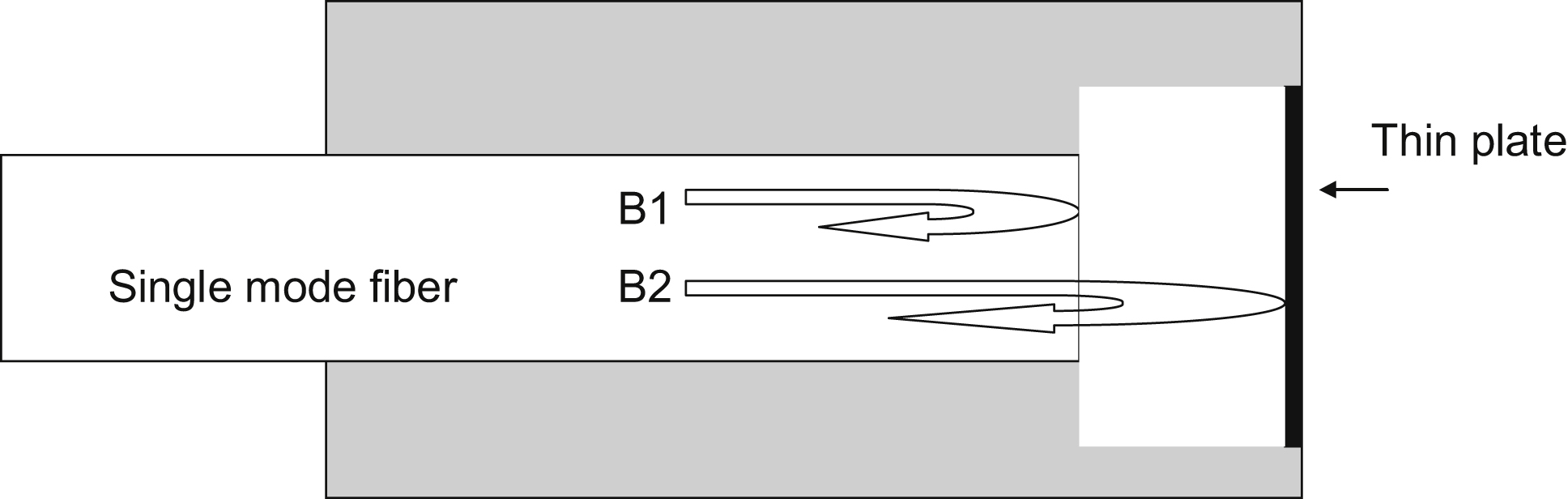
An early paper [7] describes the use of optical fiber pressure, acceleration, and skin friction sensors. All the described sensors were based on the principle of converting a change in one of the measurands into a change in displacement of one face of an external Fabry–Perot interferometer, as shown in Fig. 9.1. Deformation of the thin plate reflector results in a phase shift between the two beams B1 and B2 and thus the amplitude of the returned signal when the two beams are combined.
Measuring pressure is straightforward: a pressure applied to the thin plate reflector causes deformation. Measuring acceleration is more involved; in this case, a small mass is attached to the thin plate, and acceleration causes a measurable displacement of the mass. Perhaps the most novel method was measuring skin friction or wall shear stress. The basic idea is to mount the thin plate reflector on a thin center post, and use multiple fibers to monitor the tilt of the reflector, caused by a shear stress, at several locations on the post. The general approach of measuring deformation of a “floating” surface has also been adopted by several researchers in the field of microelectromechanical systems (MEMS), and at least one group has developed a MEMS optical sensor that also utilized a Fabry–Perot sensor to monitor the motion of a floating element [8]. In the opinion of one reviewer [9], the use of floating elements represents the most viable approach to measure wall shear stress. The authors demonstrated that during wind tunnel tests at constant velocity the sensor exhibited a constant response during the test and a return to zero at the end of the test.
A review article [10] notes that, in terms of ensuring structural integrity, optical fiber sensors can serve in two roles: load monitoring via strain sensing and damage detection via a variety of SHM methods. In the former application, optical fiber Bragg grating sensors have clear advantages over electrical strain gauges, such as ease of multiplexing, immunity to electromagnetic interference and corrosion, and light weight. In the latter application, optical fiber sensor–based SHM competes with both SHM electrical methods, such as electromechanical impedance sensing and embedded ultrasonic sensors, and classical nondestructive testing. One downside of an all optical sensing approaches for SHM is that they are passive, and while this might be adequate for, say, acoustic emission applications, the data obtained from optical fiber sensors cannot compete, in terms of information content, with, for example, the data obtained from an active system such as is used in classical ultrasonics. For this reason, several groups, reviewed in this paper, have developed hybrid approaches, using electrical piezoelectric actuators to produce an excitation and optical fiber strain sensors to detect the resulting vibrations. Going one step further, an all-optical-fiber ultrasonic system was demonstrated, using a pulsed laser source to generate, via thermal expansion, acoustic vibrations in a structure [11]. One particular advantage of optical fiber Bragg grating ultrasonic sensors is their directionality—detection of vibrations that result in displacement parallel to the fiber is some 100 times easier than that of vibrations normal to the optical fiber. Thus, using multiple fiber sensors at different orientations, the source of the vibration can be deduced.
9.3. Overview
For optical sensors (or any type of sensor) to be incorporated into aircraft, it is necessary to demonstrate that they will contribute to safety and/or lower maintenance costs. Furthermore, the chances for incorporation will be enhanced if the information derived from the sensor is readily assimilated into accepted inspection/monitoring practices. To appreciate current trends, it is important to understand some basic tenets used in aircraft design and inspection practices to ensure safety. Three major design philosophies used in the aircraft industry to ensure safety are fail-safe, safe-life, and damage tolerance. The fail-safe philosophy is based on the assumption that because it is virtually impossible to ensure that any particular component will not fail, designs should be such that failure of primary components will not have catastrophic results. SHM could be used here, in the sense that detection of a crack before it has grown to a critical size could be considered a failure event that is not catastrophic, because at the point of detection the damaged component will be replaced.
The safe-life philosophy is based on the assumption that mechanical properties are known well enough that analytical models, particularly of fatigue, can be used to predict the number of flight cycles before failure—the safe-life. Because there are several uncertainties in this approach, periodic inspections are necessary to assure that cracks have not formed. This approach assumes that components have a finite life, and thus should be retired after some time. SHM methods have the potential to reduce the number of these inspections by providing a continuous assessment of whether cracks have formed. Because fatigue cracks do not form in composites, this approach is not readily applied to these materials.
The third approach is damage tolerance, based on the idea that as long as preexisting cracks in a structure do not grow to a critical size, then the structure is still safe to use. While this approach does require periodic inspections to assure that indeed cracks have not grown to critical size, it does offer the possibility of essentially an infinite life for an aircraft, as long as the occurrence of crack growth, via periodic inspections, is monitored. This is the area in which SHM can play a large role, as it offers, potentially, the possibility of lowering the required rate of periodic inspections by providing continuous information regarding whether a crack has formed or grown. However, this approach has not yet been validated.
Boller [12] makes the important point that many aircraft today are using maneuvers that differ significantly from those anticipated when the aircraft was built, thus changing the magnitude and locations of highest stress, and inspection and monitoring regimens must be adjusted to accommodate these changes. As long as the long-term costs of these are less than the replacement costs, they will be performed. The author reports that the most common failures observed from tear-down analysis are fatigue failures (70%) and fastener failures (15%); fractures due to overstress are evidently not very common. Interestingly, most of the fatigue failures were found on the fuselage (91%)—only 4% of fatigue failures were found on the wings. Another relevant observation is that 90% of inspection work in commercial aircraft consists of visual inspection; it remains a question to what extent optical fiber, or other types of sensors, can replace this. Nevertheless, the author presents an exercise that attempts to compare the costs of conventional inspection of several components of an actual aircraft with estimated costs (including research and development costs) of using a “smart layer” SHM system, which consists of piezoelectric actuators and sensors integrated into a skin placed on the aircraft. While many assumptions go into this comparison, the author concludes that this particular health monitoring system is cost effective only for the more complex components, for which conventional inspection costs are high.
[It should be noted that current procedures with damage tolerance call for periodic inspections to see if a crack has appeared. If yes, the frequency of inspections must be increased. Thus, airframe operators have a built-in bias against any method that may promise improved crack detection, even though this may lead to a higher level of safety.]
An extensive discussion on aerospace applications of optical fiber strain sensors is contained in a NATO report [13]. In all the applications discussed here, an optical frequency domain reflectometry method, developed at NASA Langley [14], was used, with important improvements over the original design. In particular, the development of fast frequency scanned lasers has allowed the gathering of strain data from thousands of multiplexed sensors, along fibers up to 100 m long, at rates as high as 50 Hz, which is high enough to characterize many vibrational modes found in airborne aircraft. While clearly the ability to monitor so many sensors is impressive and can be of much utility, as will be described later, it should be noted that the weight and size of the interrogator, ∼10 kg and 0.02 m3, respectively, preclude using this particular approach in many lightweight vehicles.
An interesting method was used to reduce the time and effort needed to surface mount multiple fibers—encapsulating the fibers in a smart layer composed of two polyimide sheets. The method, developed by Acellent and originally designed to encapsulate thin piezoelectric sensors and actuators, allows one to apply the smart layer as a whole to a surface, reducing installation time (a good portion of which is often spent in taking care not to break the fibers) of individual fibers and also providing an added measure of protection for the fibers. It is known that good strain transfer from a sample to an optical fiber sensor depends on having a good adhesive bond, and thus using the smart layer approach can potentially lead to loss of accuracy due to the several relatively soft layers between the sample and the sensors [i.e., (1) surface/smart layer adhesive interface; (2) smart layer polyimide sheet; (3) smart layer/adhesive bond to fiber]. The authors report that good agreement was found between the smart layer–encapsulated fiber sensors and conventional strain gauges mounted on the same surface.
The report also describes in some length how optical fiber strain sensors were used to develop structural transfer functions, that is, functions that relate measured surface strains to wing shape, external loads, and fatigue life. The authors note that the development of these functions for use with optical fiber sensors was motivated by the in-flight failure of the Helios unmanned aerial vehicle (UAV; the “flying wing”), which was believed to be due to excessive wing-tip displacement. The basic idea is that if the displacement along the wing can be determined in real time, then rapid flight corrections can be made (either automatically, using onboard processing, or by a remote pilot) if the displacements approach a critical threshold, thus preventing failure. The approach uses the method developed by Ko et al. [15], where closed-form equations were developed that relate (measured) surface strains to displacements of a structure (e.g., a wing) and point loads. Both bending deflections and torsion were determined using optical fibers placed along the leading and trailing wing edges. The transfer functions are in closed form, and thus they can be evaluated in real time and used for in-flight corrections—a finite element approach would be much too slow.
Initial validation during flight of the use of optical fiber strain sensors to determine wing displacement in real time was performed by installing some 3000 sensors along the wings of the Ikhana UAV, which has a 10-m wing span. Eighteen flights were performed with full success, demonstrating the flight worthiness of the system. The sensor system, with 8000 sensors, was also successfully flown on the AeroVironment Global Observer aircraft, a fully composite UAV. The fact that the sensing system was demonstrated on the Global Observer, which is meant for long-duration flights and where weight is a large concern, is an indication that the 10-kg weight of the interrogator is considered an acceptable price to pay. Nevertheless, this reviewer feels that a case can be made that using lightweight (and relatively inexpensive) spectrometer-based interrogators of around 1 kg to interrogate tens of sensors may, in fact, be an attractive alternative in applications where saving weight is of paramount importance.
It should be noted that the transfer function approach (i.e., the Ko et al. theory) used here was validated under static loading conditions, and while this approach may be valid for determining displacements from measured surface strains under dynamic conditions, it is not obvious that dynamic loads can be determined this way. That is, the Ko theory is based on the assumption of structural equilibrium, which is not always present during flight. Also, although thousands of sensors were used in the aforementioned demonstrations, the authors did not provide analysis demonstrating that many sensors were indeed needed to get the desired results. In fact, a single accelerometer placed at the tip of each wing can provide displacement information (after integration) that could well be adequate for most applications.
The authors conclude by describing a possible trajectory for the use of optical fiber sensors in future aircraft design, test, and operation. Hundreds of thousands of sensors would cover the aircraft, providing detailed information about the strain state at high spatial resolution, allowing precise understanding of both the displacements and the structural health of the aircraft, although the authors do not go into any detail about the latter application. The large amount of information generated during the design and test phases, previously not available to designers, combined with analysis with multiphysics codes, will allow a much more comprehensive understanding of the mechanics of the aircraft, lowering uncertainty and resulting in the lowering of design margins. This in turn will result in lighter, more efficient aircraft that also are safer than previous designs. In support of these advances, the authors claim that, in current design practices, “the validity of initial design assumptions was seldom verified by comparison with databases of in service performance.” Because test data that could be used for verification have always been available in the modern era, the authors are apparently working under the premise that the large amounts of data generated by thousands of sensors will be the catalyst for the construction of databases readily accessible to designers. [However, it is not obvious in this reviewer's mind that the generation of large amounts of data will necessarily be accompanied by the ability to access these data in a meaningful way. While “data mining” of large data sets is gaining popularity, it is not yet clear that this trend will prove useful in aircraft design. In fact, sometimes important results can be obscured by too much data.]
The aircraft industry is generally considered conservative, and it remains to be seen to what extent massive numbers of sensors will be beneficial in the design, test, and operation of large passenger aircraft. There is little question, however, that more extensive data sets, provided by large amounts of sensors, will be needed to take advantage of the analysis methods appropriate for the design and operation of the lightweight and flexible UAVs of the future. In-flight failures like those of the Comet and Aloha Airlines are known to be the catalysts for changes in design rules to increase safety, and failures such as the in-flight failure of the Helios and other UAVs have evidently spurred the funding of research and development efforts to utilize sensors so that flight maneuvers keep the aircraft within safe limits.
Garcia et al. [15a] review some recent work on both silica and plastic fibers that is worth noting. In one series of tests, optical fiber Bragg grating sensors were bonded to a metal structure that was subsequently aged under moist conditions. It was found that the sensitivity (i.e., shift in wavelength/applied strain) of the gratings changed by up to 50%, indicating that aging under a moist atmosphere can change the optical properties of the fiber, a very important observation, because Bragg grating sensors are usually thought of as immune to environmental influences.
The use of a plastic optical fiber (POF) sensor is also discussed, with the main advantage being lower cost, for both the fiber and the interrogator, although performance is compromised. Also, plastic fiber sensors can be used out to almost 10% strain, compared to the 1% strain capability typical of commercial fibers. While single-mode POFs, and low-quality POF Bragg gratings, have been described in the literature, the approach taken here is one of intensity modulation in multimode plastic fiber. The basic principle is to compare the phase of light propagating in the sensor (a length of POF) with the phase of a reference length of fiber. Elongation of the sensor results in a change in phase, which is detected. For this approach to work, the sensor fiber length must be many centimeters long. While it was demonstrated that strain could be measured, the signal-to-noise ratio was poor.
Next, the authors describe the use of long-period gratings in microstructured POFs for strain sensing. In this type of fiber, the core consists of many individual air-filled channels, similar to photonic crystal glass optical fibers. The authors note that these fibers can sustain the propagation of single modes (single-mode plastic fiber is not easy to procure) while also maintaining the state of polarization. Long-period gratings are made in a manner analogous to Bragg gratings, the difference being a much longer period in the variation in refractive index. It turns out that at a certain wavelength the core modes leak into the cladding, resulting in a notch in the transmission spectrum. The key point is that this wavelength, like in Bragg gratings, is dependent on strain. In the case described here, the notch wavelength was around 600 nm, which permitted the use of an inexpensive visible spectrometer for sensor interrogation—a very significant advantage. The grating length was 60 mm; however, there was no discussion of whether shorter lengths would be possible. Successful operation of a sensor with a 60-mm length was demonstrated. So, the large strain capability of POFs may allow this type of sensor to be selected when it is desired to measure the strain of very flexible structures. Also, it should be noted that because Young's modulus of glass is orders of magnitude larger than that of plastic fiber, the influence of glass fibers on the deformation of very thin structures can lead to inaccuracies in the measurement.
The authors conclude with a discussion of the use of an optical fiber displacement sensor to monitor the vibration of turbine blades in a jet engine, with the end goal of minimizing the clearance between the blade tip and the casing to improve efficiency. This type of sensor relies on monitoring the intensity of reflected light, and commercial versions are available. Two types of vibration monitoring are described: radial and tangential. Radial vibration is straightforward, as radial vibrations result directly in changes in displacement. Tangential vibrations are harder to monitor, but it is shown that by precisely comparing the displacement signals with the predicted response (i.e., perfect rotation with no vibrations), the vibration characteristics of all the individual blades can be continuously monitored and, presumably, defects detected.
Pisupati et al. [16] provide a brief but informative review of how SHM can benefit the aircraft industry. Some interesting points are that SHM can play a larger role in extending service life than in helping reduce maintenance during the design life, because schedule-based maintenance is probably adequate for the latter. While the basic SHM approach (i.e., real time) is meant to replace scheduled NDE, some of the basic technologies are shared, such as acoustic ultrasonics and electromagnetic methods.
Lawson et al. [17] present a comprehensive discussion on their experience using optical fiber Bragg grating strain sensors and optical fiber extrinsic pressure sensors during flight testing. They also point out that contemplating the use of electrical sensors for these measurements must take into account electromagnetic compatibility requirements that optical fiber sensors are exempt from. The optical fiber pressure sensor was based on the widely used Fabry–Perot cavity type (measures distance between end of fiber and membrane), using a scanning laser to obtain absolute distance measurements, and including a vent in the cavity to allow the measurement of differential pressure. A practical challenge was using the (required) flight-certified data acquisition system. The SmartScan Aero Interrogator, capable of scanning at a rate of up to 2.5 kHz, was used for both the Bragg grating and the pressure sensors. Kulite pressure gauges and conventional foil strain gauges were used to validate the data from the optical fiber sensors. A Bulldog light aircraft was used as the test vehicle. Four optical fiber Bragg grating (FBG) strain sensors were glued along the wing and covered with tape, and a fifth FBG to measure temperature was isolated from the strain in the wing by being placed in a tube. The pressure sensor was located on the fuselage behind the wing. During flight the optical fiber sensors performed well, with both the Bragg grating and the pressure sensors responding to the changes in deformation of the wing and changes in pressure, respectively, as the plane executed a spin. Using beam theory and assuming a uniform distributed load, the measured surface strains were used to calculate the g-loads during various maneuvers. These derived loads correlated well with accelerations obtained using an altitude heading reference system.
Yari et al. [18] present a brief review of their private sector efforts in Japan to implement an optical fiber SHM system based on Brillouin optical correlation domain analysis (BOCDA). In this approach, two counterpropagating light beams (pump and probe), of slightly different frequencies, are launched into a single-mode fiber. The frequency of the probe beam is adjusted so that the two beams are continuously correlated at a single point in the fiber, the sensing region, at which point the Brillouin scattering is strongest. Because the frequency of the scattering light depends on strain, the method can be used to measure strain in a distributed manner by varying the frequency of the probe beam. Advantages of this method include the ability to measure strain at any point in the fiber, which can be up to around 1 km in length, and the ability to use ordinary single-mode optical fiber. Disadvantages of the method include limited bandwidth (less than a kilohertz); lower strain resolution (in this case, 13 με) compared to, say, Bragg grating sensors; and the large weight of the interrogator (in this case, 45 kg). Consideration of these features would indicate that the best utilization of this method would be in the field of SHM of large civil infrastructures such as bridges, roads, and pipelines, and so it is somewhat curious that it was applied for SHM of an aerospace structure. In any case, the method was used to monitor the deformation of part of the fuselage of a Mitsubishi MU-300 business jet, after the interrogator successfully passed vibration testing. During both flight and landing the BOCDA strain agreed with that measured using a conventional strain gauge.
[Opinion: In this reviewer's opinion, this effort illustrates a feature common to many SHM research efforts, where the technology is applied without taking into account the real needs of the application.]
Pak [19] provides an approach to the use of optical fiber strain sensors to determine wing shape. Pak notes that previous methods provided displacement only at the measured strain locations. In his approach, the measured strain values are used, together with a finite element model of the structure, to determine the overall displacement and shape of the structure. The process consists of two basic steps. First, the strain readings along the optical fiber are curve fitted and integrated twice to obtain the deflection and slope along the fiber:
where w is the deflection, x is the distance along fiber, κ is the curvature, h is the distance from the neutral axis, and ε is the strain. Thus,
These deflection values are combined with a finite element model to obtain the deflection of the entire structure.
The procedure was tested on a plate that had loads applied at various points and whose deflection was measured directly using photogrammetry. The plate was also instrumented with optical fiber strain sensors, but no details were provided (although the fiber optic strain system mentioned in the article probably refers to the use of a dense array of closely spaced Bragg gratings). The computed deflections matched well with those measured using photogrammetry. While this approach seems to be able to provide a more comprehensive description of wing shape, the use of finite element modeling, which is computationally intensive, as part of the analysis may preclude its use in real time, in flight wing shape determination, needed for flight control.
Minakuchi et al. [19a] discuss three main efforts in the use of optical fiber sensors for aerospace applications: damage detection in composites using measured strain field perturbations, shape reconstruction from strain values, and a hybrid approach in which optical fiber sensors are combined with comparative vacuum monitoring (CVM). The first type of damage described is that formed around bolted composite joints, monitored with an optical fiber placed nearby. It was found that the residual strain signal obtained from BOCDA increased as the joint was stressed, demonstrating the accumulation of damage. The fiber was placed at various angles to the direction of load application, and at various distances from the bolt, and therefore the special extent and direction of growth of the damage could be inferred from the measured strain values. These conclusions were verified using X-ray radiography.
The authors also present a method that “remembers” the stress applied to a composite during impact and the degree of subsequent undersurface damage. The method is based on placing thin wires and, adjacent to the wires, optical FBG sensors, under the faceplate of a composite. When the faceplate is deformed, the wires retain the deformation (even after the faceplate may partially recover its shape). Because the FBGs are in close proximity to the wires, the strain field around the bent wire splits the reflection peak, and thus serves as an indication of damage. The advantage of this method over real-time impact detection methods is that high-speed detection methods are not required.
The authors also discuss the use of distributed strain measurements, based on Brillouin scattering, to infer the shape of a deformed plate. While the claim is made that because the method utilizes strain gradient measurements, and not just strain, it is superior to other shape reconstruction methods, quantitative comparisons to other published methods are not provided.
The authors point out that, despite the advantage of distributed sensing in optical fibers over long fiber lengths, the method is not robust—a single break in the fiber can render the entire system unusable, and repair is very difficult, and impossible in fibers embedded in a composite. The authors thus suggest a different approach: using surface-mounted optical fibers as communication links to surface-mounted sensors. As an example, they present an application of this approach to monitoring the pressure in CVM sensors. A method to detect cracks, a CVM sensor, consists of a chamber that is initially under vacuum. When a crack interacts with the sensor membrane, a leak in the vacuum occurs; the loss in vacuum, measured with a pressure sensor, is thus an indication of the formation of a crack. In the authors' scheme, surface-bonded optical fiber pressure sensors are ideal candidates to measure the loss in vacuum. Because the fibers are on the surface, fiber breakage can be readily repaired.
While many optical fiber distributed sensing methods are described in the general literature, two seem to be the most popular for aerospace applications: FBG sensors and BOCDA, which is basically a sensing and interrogation method. In addition, the two main interrogation methods for FBGs are wavelength division multiplexing and optical frequency domain reflectometry [14]. The latter approach is able to interrogate thousands of low-reflectivity Bragg gratings of nominally equal wavelength and, being developed by NASA, has established itself as a workhorse method by this organization. While this method does require the formation of Bragg gratings, the ability to use low-reflectivity gratings allows the use of gratings formed during production on a fiber draw tower, significantly lowering the cost.
The method is based on recording the interference pattern formed by multiple Bragg gratings and an air-spaced reflector when the wavelength of the input light is scanned. Because the frequency of the fringes is related to the distance between the reflector and the grating, a Fourier transform of the entire interferogram provides a determination of the location of each grating. A Fourier transform of selected portions of the interferogram then provides the wavelength dependency of each grating, i.e., the reflection spectrum. The instrumentation required for this method includes the scanning laser, a gigahertz photodetector, and a gigahertz analog-to-digital converter. While the reported weight of interrogators using this method is on the order of 10 kg, it is probable that significant weight reductions may occur when MEMS-based mode-hop-free scanning lasers are developed.
A variation on this method relies on analysis of the Rayleigh scatter found in standard single-mode fibers, analogous to Bragg grating reflectors [14]. This method can provide a spatial resolution down to millimeters.
Tur et al. [19b] used distributed (residual) strain sensing based on Rayleigh scattering to monitor damage in composite fuselage panels. They identified three criteria to determine when permanent damage is present: (1) linearity of strain with load, (2) stability of the strain signal during extended loading, and (3) absence of residual strain after impact or loading. The use of these criteria was demonstrated in laboratory experiments. It should be noted that while in flight only the third criterion is practical; the other two criteria could prove useful during ground inspections. In fact, combining the application of either a linearly increasing or a constant load with strain measurements at various locations is a form of “active” sensing that provides much more information than passive strain sensing.
Many workers have analyzed vibrations of helicopter components as a means to detect defects. Kiddy et al. [20] discuss the application of optical FBG sensors to record vibrations of the OH-58C helicopter transmission. Noting that accelerometers are often used for this purpose, the authors suggest that the ability to place optical strain sensors in confined spaces, plus their immunity to electromagnetic interference, should make them ideal sensors for this application. To demonstrate the method, 13 optical FBG sensors were bonded to a tension band that was subsequently tightened around the outside of the “sun” gear containing several planetary gears. Accelerometers were also bonded to the gear, and the Bragg grating sensors were interrogated at a rate of 1 kHz. Two main frequency components were observed as the transmission was operated. The large-amplitude, low-frequency component was attributed to the motion of the planetary gear, and the much smaller amplitude and higher frequency mode was attributed to the gears; the latter vibrations were used to assess gear damage. First, vibration data were obtained when no damage was present. Twelve types of defects, such as root cracks and pitting, were next introduced into the transmission, although it was not specified how. Nine different criteria were used to quantify the difference between the damage and the undamaged spectra, and a large variation in results was found between the sensors. This variation was believed to be due to both intrinsic lack of symmetry of the transmission housing and variability in tension in the band and bonding between the sensors and the band. Owing to this variability, only about half of the defects could be detected with high reliability.
Owing to the low signal-to-noise ratio of the data from the accelerometer, these data were not used for damage detection, although a comparison with the optical fiber data would have been useful. Also, it would have been helpful to report whether the noise from the accelerometer (which is shown to be high frequency) was due to mechanical vibrations, in which case useful information could perhaps be extracted, or to electrical noise. These considerations are important, as the 1-kHz interrogation rate of the Bragg grating sensor interrogator could easily have masked higher frequency components containing important information.
Wada et al. [21] present an informative demonstration of the use of Bragg grating sensors to monitor vibration and deflection of helicopter blades, noting that these influences can decrease service life. To monitor these vibrations, an optical frequency domain reflectometer, with a measurement speed of 150 Hz (set by the frequency scan speed of the laser source), was used to interrogate multiple optical FBG sensors bonded along a 5.5-m-long helicopter blade, along with 20 accelerometers. It was found that the strain resolution obtained from the fiber sensors and interrogator was about 5 με—considerably less than the 1 με obtainable using other types of interrogators.
Vibrations were induced in the blade by rapidly releasing the preloaded blade. The strain measurement obtained from the Bragg grating sensors were converted to deflection values via Eq. (9.1), based on cantilever beam theory. The authors presented the vibration results in terms of both strain-based and deflection-based frequency response functions, and while the first two vibration modes, at 1.5 and 8.8 Hz, were clearly evident, signal averaging was sometimes (i.e., depending on where along the blade the measurements were obtained) needed to extract the third mode at 22 Hz. Interestingly, in addition to the first three modes, a fourth and fifth mode were readily observed in the data obtained from the accelerometers, due to a significantly higher signal-to-noise ratio (SNR) compared to the optical fiber sensors. The authors speculate that the integration process involved in deriving the displacement, via Eq. (9.1), is partially responsible for the lower SNR of the optical fiber sensors, although it must be noted that the poor SNR was also evident in the strain-based frequency response functions. Although not discussed by the authors, the poorer SNR associated with the optical fiber sensors could be also due to the fact that very high speed photodetectors were used (8 GHz), which generally do not have noise characteristics as good as those of lower speed detectors. The mode shapes were also determined, and while for modes 1 and 2 there was good agreement between the optical fiber sensors and the accelerometers, the mode 3 shape determined from the optical fiber sensors was considered erroneous.
Li et al. [22] present a detailed discussion of the use of optical fiber strain sensors for monitoring the integrity of composite repair patches, which are sometimes used to repair both metallic and composite structures. They make the important observation that current regulations state that a damaged structure can be certified only if the strength of the structure (repaired or not), in the damaged state, has a residual strength of at least 1.2 times the design load. Therefore, a damaged structure whose residual strength (in the damaged condition) is less than this value can never be used, even if repaired. However, the authors suggest that if the integrity of the repair is continuously monitored, then the structure may be allowed to fly, as an indication of damage growth can be used as a trigger to halt operations. This is perhaps the one of the clearest applications of where SHM can be adopted.
To test the usefulness of optical fiber sensors for this application, a hole was made in a composite panel, over which composite patches were bonded on both sides. One optical FBG sensor, used as a reference, was placed far from the patch, while another was placed on the patch itself. Various levels of debonding were introduced into the patch-composite joint by inserting Teflon tape between the two surfaces. After each level of damage was established, the composite panel was then loaded in tension to various levels while the strains were monitored. The basic premise was that increasing levels of debonding between the panel and patch would result in less stress transfer into the patch, and thus less strain. Thus, a measure of strain in the patch, referenced to the reference strain sensor, would provide a measure of damage. Finite element modeling of the system indicated that the effect of disbonds was rather local, and that disbonds shorter than 9 mm would not be detectible at the location of the sensor.
Two types of sensor interrogation were used to interrogate the reference grating and sensor grating. The first method was the use of an optical spectrum analyzer, and the second method was basically the “matched” grating approach, where the output of the grating sensor was input into the reference sensor, after which was placed a photodetector. Because the spectra of the gratings were essentially identical, the photodetector would indicate little signal in the no-load condition. When the load was increased, and the sensor grating experienced a higher level of strain compared to the reference sensor, the photodetector would record a larger signal. This interrogation approach, directly comparing the spectra of the reference and sensor gratings, was both much less expensive and much faster.
The experimental results indicated that the presence of the disbonds could be readily verified, with the difference between the gratings being larger with larger disbonds and larger loads. Thus, while damage can be observed on a loaded structure, quantification requires knowledge of both the applied load and the measured strain difference. Because the load is rarely known in practice, it would appear that this approach has little quantitative value. However, the authors suggest a solution: because the strain difference appears to be the product of both the disbond length and the load, they introduce a parameter called the “threat factor,” which is a function of disbond length and load and represented by the strain differential. The threat factor concept simply implies that the risk to the repair patch is a function of both loading and size of the damage, and a threshold value can be established above which operations should be limited. However, it should be noted that it is not clear that this approach would be accepted by aerospace regulatory bodies. In any case, this effort clearly demonstrates the importance of measuring not only strain (a passive measurement) but also application of a load as part of an SHM approach.
Composites are not only used in aircraft, they are also finding use in space structures. Park el al. [23] performed experiments to investigate the effects of low earth orbit on optical FBGs. Optical FBGs, both bare and embedded in composites, were subjected to large thermal cycling (−30 to 100°C), UV radiation, high vacuum, and bombardment (under vacuum) with high-energy oxygen ions. It was found that the peak in the reflection spectrum shifted by about 0.5 nm to longer wavelengths. The authors suggested that this was due to relaxation in the fiber, resulting in a slightly longer grating. Grating sensors were placed at various depths in the graphite epoxy laminate, which had a total thickness of 1.7 mm. It was found that all the gratings exhibited significant wavelength shifts, indicative of dimensional changes in the composite due to outgassing during vacuum. Also, differences in wavelength shifts between sensors at different depths in the composite was believed to be due to degradation of the matrix material resulting from the oxygen bombardment.
A study of the expected effects of the space environment on optical fibers per se was performed by Freibele et al. [24]. It was found that significant transmission losses resulted from both gamma and proton radiation, and, for sensors with long fiber lengths, such as gyroscopes, these effects could be detrimental.
It was shown earlier [4] that embedding optical fibers perpendicular to the lamina orientation can result in a degradation in strength of a composite laminate, and while this embedding configuration is thus often avoided, there is still residual concern in the aerospace community about embedding fibers in composites where composite failure can be catastrophic. Considering that the diameter of a typical single-mode fiber used for sensors, 250 μm, is much larger than many prepregs (preimpregnated graphite fiber bundles), this concern is understandable. To significantly alleviate these concerns, Satori et al. [25] developed optical fibers with a diameter of only 40 μm, inscribed Bragg gratings in the fibers, and successfully embedded the fibers in composites. High-temperature annealing of the fibers (after the gratings were formed) was performed to ensure long-term stability. This step was desired because hydrogen loading was used to enhance the reflectivity of the gratings, and the slow diffusion of this hydrogen out of the fiber has been shown to slightly change the peak wavelength of the Bragg gratings. The small-diameter optical fiber sensors survived embedding in the composites, composite curing, and subsequent tensile tests, demonstrating that, while handling such small-diameter fibers was undoubtedly difficult, once the fibers were embedded in the composite, they were fairly well protected (of course, ensuring durability at points of ingress is still a concern).
Another approach to determining the modal shape of wings, with the ultimate goal of detecting damage, is provided by Cusano et al. [26]. In this effort a composite wing, rather than being instrumented with many strain sensors, was instrumented with only three Bragg grating strain sensors, along with several accelerometers. However, impact loading by an instrumented hammer was applied at 29 locations along the wing. Because only three Bragg gratings were used, the interrogator system was particularly simple—each Bragg grating was matched with a linear optical filter, allowing acquisition rates of up to 50 kHz with the available equipment. Following each impact at each location, strain and acceleration data were obtained. Strain frequency response functions were computed, and mode shapes derived, according to the procedure described in Ref. [27]. Good agreement was found between the mode shapes and the frequencies found using the data obtained from the optical fiber strain sensors and those obtained using accelerometers. Normal, bending, and torsional modes were all found. And modal frequencies as high as 160 Hz were identified—much higher than that found in Ref. [21]. Interestingly, that effort was performed 10 years after this one. It would be useful to know if the use of multiple impact points, rather than multiple strain measurements, is advantageous in characterizing vibration modes. While the use of multiple sensors is an approach well accepted in the SHM community, the use of multiple piezoelectric actuators has also been discussed, for example, in the smart skin approach. Of course, the force applied by an instrumented hammer is much higher than the force that can be applied in the smart skin method.
9.4. Concluding Remarks
After about two decades of development, and countless papers and conferences describing impressive results demonstrating how this technology can help in detecting defects and in determining wing shapes, optical fiber sensors have not been significantly accepted by the aerospace end user community. It was suggested here that there are both technical and human reasons for this, such as, respectively, difficulty in demonstrating that the probability of detection of flaws with optical fiber sensors is comparable to the current state-of-the-art NDI methods, and the fact that optical fiber sensor concepts are often developed without clear direction from the aerospace community. It is sobering to note that in a summary of projects of the 6-year European effort, “Smart Intelligent Aircraft Structures” (SARISTU) [28], there are few, if any, real-world applications of optical fiber sensors. This reviewer believes there is a future for this technology in the aerospace field, but clear advantages of optical fiber sensors over current methods must be demonstrated. Perhaps the best way to reach this goal is for the optical fiber sensor community to invest more effort in looking for niche applications—once a foothold is established, more applications will follow.
..................Content has been hidden....................
You can't read the all page of ebook, please click here login for view all page.