
19
Instrumentation and Equipments in Power Station
Contents
19.1 Elements of instrumentation
19.2 Important instruments on steam generator and turbine
19.3 Combustion control
19.4 Introduction to generator and exciters
19.5 Earthing of power system
19.6 Power and unit transformer
19.7 Circuit breakers
19.8 Protective equipments
19.9 Control board equipment
19.10 Switch gear for power station auxiliaries
19.11 Testing of power plants and heat balance
19.12 Questions
19.1 ELEMENTS OF INSTRUMENTATION
For optimum operation of the power stations, it is essential to depend on automation and control utilizing very sophisticated controlling and monitoring techniques for power systems. Unlike the olden-day plants where control and monitoring systems were done operators utilizing simple circuits, the modern-day power plants are controlled almost entirely on computerized equipment, which has considerably simplified the control of processes involving multiple variables. In order to maximize the efficiency and availability, control and instrumentation or automation in power plants is inevitable.
In a typical power station, the major systems for power plant monitoring and control are as follows.
19.1.1 Process Control System
This is a closed-loop control system that automatically collects plant data by reading instruments, and monitors the physical and electrical parameters associated with the boiler, turbine and generator continuously. The system is used to control pumps, valves and switches for routine functions and during start-up or shutdown periods. Alarms and events are logged for better monitoring of the system.
19.1.2 Operational Monitoring System
This system collects the operational data that could be utilized by the plant operators for record keeping, report writing and analysis.
19.1.3 Automatic Generation Control System
This system adjusts the generation capacity against load, thereby maintaining the quality and minimizing the cost of energy production and transmission.
19.1.4 Load Frequency Control System
This system is used to monitor generation load by maintaining frequency at the scheduled value. It also monitors net power interchanges with neighbouring control areas at the scheduled values and power allocation among generating units at economical rates.
19.1.5 Power Plant Maintenance
This system stores the information required for analysis of maintenance costs and evaluation of equipment performance. The system being an interactive one could be used by the plant personnel to enter problem data, planning data and work execution data, apart from entry and maintenance of an equipment database and for easy access to equipment history.
19.1.6 Plant Monitoring System
This system collects data for the purpose of fuel monitoring and performance calculations without performing any control actions. Data stored in the system may be retrieved to prepare reports and performance analysis.
19.2 IMPORTANT INSTRUMENTS ON STEAM GENERATOR AND TURBINE
Instrumentation on steam generator and turbines is very essential and vital for better control and problem rectification. Major parameters that need to be monitored are pressure, temperature, water level, frequency and feed rate. In this section, some of the important instruments used for control and installed on turbines and generators are discussed.
19.2.1 Drum Water-Level Control
To overcome the problems associated with water carryover, drum-level water control is very much essential. Higher level of water means water particles being carried into the super heater and turbine section, damaging the turbine blades and boiler tubes. This will result in additional maintenance cost. On the contrary, if the water level is too low, tubes may be overheated, ruptured or melted, thereby causing serious damage to the system and the injury or death to working personnel. There are three different methods of controlling the drum level, namely using single element, two elements or three elements.
19.2.1.1 Single-Element Feed Water Control
It is a simple feedback loop controlling the drum level. In a single-element control system, the level transmitter (LT) sends a signal to the level controller. The process variable that is the input signal in this case is compared with the set value or set point (SP). The output signal is modified and adjusts to the set value of final control device, which could be a control valve, pump speed control or both as shown in Figure 19.1.
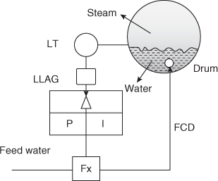
Fig. 19.1 Single-Element Feedwater Control
Figure 19.2 shows P&ID control of a single-element feedwater control.

Fig. 19.2 P&ID Diagram for Single-Element Feedwater Control
19.2.1.2 Two-Element Feedwater Control

Fig. 19.3 Two-Element Feedwater Control
In a two-element system (Figure 19.3), steam flow is also taken into consideration (secondary variable). This system operates on simple feedback and feed-forward control principle. In this system, the secondary variable is related to a manipulated variable, which causes a change in the primary variable. On receiving the steam flow and drum-level controller signal, the steam flow adjusts the feedwater control valve
19.2.1.3 Three-Element Feedwater Control
The three-element system shown in Figure 19.4 combines or relates three parameters, namely steam flow, water flow in addition to drum-level control using a simple feedback, feed-forward and cascade control loop. Based on the steam flow and drum-level controller signal, the steam flow adjusts the feedwater control valve. By adding feedwater flow, the measured value is fed back to the controller.

Fig. 19.4 The Three-Element System
19.3 COMBUSTION CONTROL
The phenomenon of combustion is far more complex than expected. When fuel and air supply to the furnace at any given instance of time is chemically ideal for combustion, it is known as stoichiometric fuel air ratio. However, given the practical conditions, it is always essential to supply excess air than the theoretically correct quantity. Any oversupply beyond this excess amount results in drop in efficiency of combustion and undesirable excess flow through the chimney.
To ensure sufficient amount of steam generation at the requisite pressure and to maintain correct proportion of fuel and air in a furnace for complete combustion, control of combustion in the furnace is very much essential. Control of combustion may be by manual or by automatic means. Automatic control of combustion is used to distribute the load evenly on the boiler as per the changing demand. Combustion can be effectively controlled by regulating the quantities of air and fuel or both. To ensure that products of combustion flow into the chimney at proper speed, it is essential to regulate differential gas pressure in the furnace. In case of automatic control, the controlling devices operate based on the change in pressure of steam.
Automatic combustion control works based on steam demand and results in efficient control of combustion. It is safer compared to manual control and saves manual labour. It comes into operation when any one of combination of the following fluctuations in the system occur: (i) steam pressure, (ii) steam flow rate and (iii) furnace draft. The action of primary forces is magnified through the master controller that in turn operates the concerned elements through electric, hydraulic or pneumatic forces.
Figure 19.5 shows a typical automatic combustion control system. The master controller M operates when the steam pressure falls below the required level. This activates the servo-motor coupled with the vanes of the ID fan that opens the air damper slightly. Simultaneously the secondary fan air damper also opens proportionately. As induced draft changes in the furnace, relay 1 (R1) operates and adjusts the FD fan vanes until stability is restored in the combustion chamber. This results in an increased flow rate of air through the passage P. Due to increased air flow rate, relay 2 (R2) is actuated, which speeds up the stoker motor to supply extra fuel. Hand adjustments are provided to the servo-motor and to the master controller to advance or retard the entire working system.
When the steam pressure increases, all the above actions are reversed.
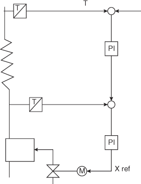
19.3.1 Super Heat Temperature Control
The super heaters are used to increase the temperature of steam to the required turbine inlet condition and hence form part of a multivariable system. Figure 19.6 shows a simple super heater steam temperature control system. It is a cascade control based on fixed PID controllers in which the controlled variable is the outlet temperature. The inner loop that is faster than the outer loop has to reject temperature disturbances, originating upstream for this purpose. The system performance can be improved further by introducing load-dependent gain scheduling in the inner control loop.
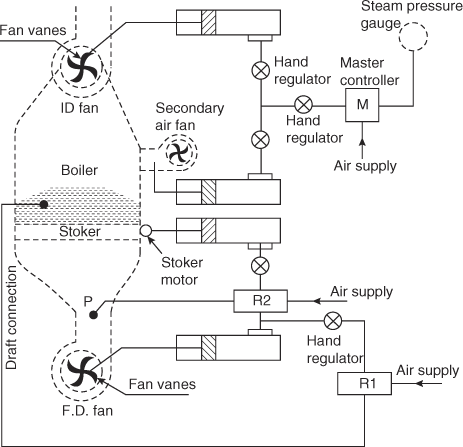
Fig. 19.5 A Typical Automatic Combustion Control System
19.4 INTRODUCTION TO GENERATOR AND EXCITERS
According to Faraday's law, when an electric conductor is moved through a magnetic field, an electrical voltage is induced in the conductor, the magnitude of which is directly proportional to the strength of the magnetic field and the rate at which the conductor crosses the magnetic field. According to Lenz's law, the induced voltage has a polarity that will oppose the change causing the induction. This natural phenomenon is known as generator action and is given by Faraday's law of electro-magnetic induction.
If Vind is the induced voltage, ΔØ is the change in flux density, Δt is the change in time, then induced voltage is given by the following relation:
Vind = ΔØ/Δt
All rotary generators built today use the basic principles of generator action as shown in Figure 19.7. When a magnetic field moves across a stationary conductor, a voltage is induced in the conductor. Reversing the direction of movement of the magnetic field will cause the direction of the induced voltage and the current also to reverse.
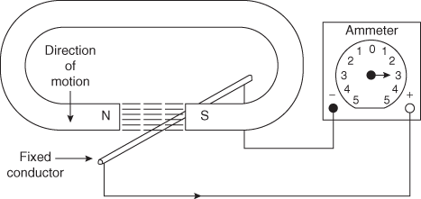
Fig. 19.7 Working Principle of a Generator
Figure 19.8 shows the construction of a basic generator.

Fig. 19.8 Construction of a Basic Generator
19.4.1 The Elementary AC Generator
An elementary ac generator is shown in Figure 19.9. It consists of a conductor or loop of wire in a magnetic field produced using an electromagnet. The two ends of the loop are connected to slip rings and are in contact with two brushes as shown. When the loop is rotated, it cuts magnetic lines of force, first in one direction and then in the other direction.
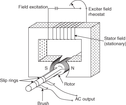
Fig. 19.9 An Elementary AC Generator
During the first half turn of rotation, a positive current is produced, whereas in the second half, a negative current is generated, completing one cycle of ac generation, as shown in Figure 19.10.

Fig. 19.10 An AC Generator Working Principle
19.4.2 Development of the Sine Wave
Referring to Figure 19.11, the instant the loop is in the vertical position, the loop sides move parallel to the field and do not cut the magnetic lines of force. Hence, there is no voltage induced in the loop. As the loop rotates further, the sides will cut the magnetic lines of force inducing voltage in the loop. When the loop is in the horizontal position (90o), maximum voltage is induced.
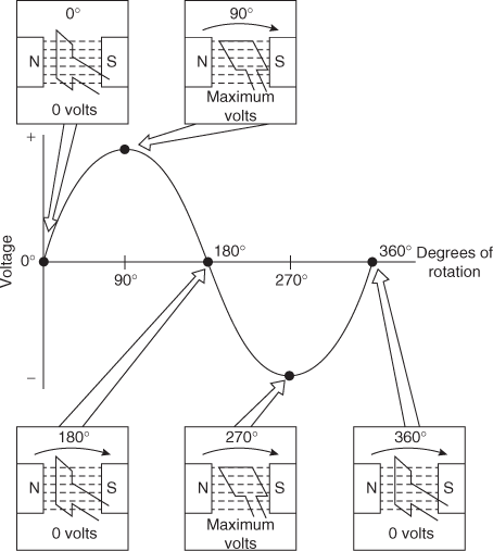
Fig. 19.11 Development of Sine Wave
The rotation of the coil through 360° results in an ac sine wave output as depicted in Figure 19.12.
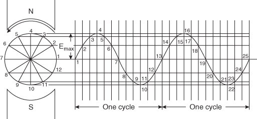
Fig. 19.12 Sine Wave
Three-phase voltage is developed utilizes the same principle of development of single-phase voltage. To develop three-phase voltage, three coils are required to be positioned at 120 electrical degrees apart as shown in Figure 19.13. A rotating magnetic field induces voltage in the coils that when aggregated produces the three-phase voltage pattern.

Fig. 19.13 Three-Phase Voltage Development
19.4.3 Types of Generators
Essentially, there are two basic types of generators, namely, DC and AC generators. AC generators are further classified as follows:
- Asynchronous (induction) generators
- Synchronous generators
19.4.3.1 Induction Generators
The induction generator is basically an induction motor driven above its synchronous speed by an amount not exceeding the full load slip the unit would have as a motor. For example for a motor with a synchronous speed of 1,200 rpm, assuming a full load slip of 3 per cent, the full load speed would be 1,164 rpm. This unit could also be driven by an external prime mover at 1,236 rpm for use as an induction generator. However, the induction generator requires VARs for excitation. The VARs may be supplied either by capacitors or from the utility grid. The former requires complex control. Induction generators are simple in construction and inexpensive, but they offer little control over their output. The induction generator does not require a separate DC excitation, regulator controls, frequency control or governor.
19.4.3.2 Synchronous Generators
Synchronous generators offer precise control of voltage, frequency, VARs and WATTs, etc., by utilizing voltage regulators and governors. A synchronous generator has a stationary armature winding, known as stator. To obtain the desired terminal voltage, the wires are connected in series or parallel. The armature winding is placed into a slotted laminated steel core. The rotor forms the other major part of the synchronous machine. A magnetic flux developed across the air gap between the rotor and stator generates an EMF. This magnetic flux developed by the DC field poles crosses the air gap of the stator windings, developing a sinusoidal voltage at the generator output terminals. This is known as electromagnetic induction.
By controlling the amount of DC exciting current supplied to the field, the magnitude of the AC voltage generated can be controlled. The frequency of the voltage developed by the generator depends on the speed of the rotor and the number of field poles. For example, for a 60 Hz system,
Frequency = speed (rpm)*pole pairs/60
19.4.4 Generator Parts and Function
Major parts and functions of generator are as follows:
Generator frame gives the structural strength and rigidity and serves as a housing to guide cooling air flow.
Collector rings provide a connection and path for DC power into the rotating field windings.
Main coupling connects to the drive shaft.
Generator fan provides continuous circulation of cooling air.
Generator coolers remove heat from the generator cooling air.
Stator core houses the stationary windings forming a magnetic path necessary for induced voltages.
Inner end shield forms a path for cooled air.
Rotating field induces AC voltage in the stator windings.
Stator coil end turns get formed when coils leave one slot in a stator core and are returned to a different slot.
Terminal leads conduct the three-phase voltage and current flow from the generator stator to the external system.
Air gap is the radial clearance between the rotating field and the stator core.
19.4.5 The Exciter
The exciter is the power source used to supply the DC magnetizing current to the field windings of a synchronous generator, inducing AC voltage and current in the generator armature.
There are two basic kinds of exciters, namely rotating and static exciters:
1. Rotating (brush and brushless)
Brushless exciters do not require slip-rings, commutators, brushes and are practically maintenance free. Brush-type exciters require slip-rings, commutators and brushes and require periodic maintenance
2. Static exciters (shunt and series)
Static excitation is with no moving parts. It provides faster transient response than rotary exciters. They may be of two types as follows:
- Shunt type: operating field power from generator output voltage
- Series type: operating field power from generator output voltage and current
Figure 19.14 show conventional, static and brushless exciters.

Fig. 19.14 (a) Conventional, (b) static and (c) brushless exciters
The amount of excitation required to maintain the output voltage constant is a function of the generator load. As the generator load increases, the amount of excitation increases. The amount of excitation required by a generator for a particular load is defined by the ‘generator saturation curve’ as shown in Figure 19.15.

Fig. 19.15 Three-phase voltage development
The amount of power that a generator can deliver is defined by the ‘generator capability curve’ as shown in Figure 19.16.

Fig. 19.16 Three-phase voltage development
19.5 EARTHING OF POWER SYSTEM
The main intention of grounding/earthing systems in power station is to provide a common ground reference for normal operation of electrical equipments including automation and measurement systems. In addition, a grounding system ensures the safety of the working personnel and prevents the insulation and other devices from possible damage owing to faulty power supply, lightning, etc. An ideal grounding system should
- have appropriate ground impedance at both low- and high-level frequencies.
- minimize the maximum values of voltages between different points at conductors and the earth surface.
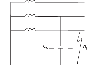
Fig. 19.17 Earth Fault in a Solidly Earthed Network
A power system can have more than one neutral point, and it is not necessary that all neutral points of one system be connected to earth, using the same earthing method. Two important functions of neutral earthing are to detect earth faults and to control the fault current. This is because large fault currents can lead to potential rise of exposed parts of the power system reaching dangerous levels. Power systems could be solidly earthed or non-solidly earthed. The latter category includes isolated neutral, resistance and resonant earthing.
In a solidly earthed system, a number of transformer neutrals are directly earthed. A single-phase earth fault current in a solidly earthed system as shown in Figure 19.17 may exceed three-phase fault current. To reduce the magnitude of the current, some of the neutrals are left unearthed.
19.6 POWER AND UNIT TRANSFORMER
As per ANSI/IEEE definition, a transformer is a static electrical device involving no continuously moving parts, used in electric power systems to transfer power between circuits through the use of electromagnetic induction.
Since generation of electrical power in low voltage level is very much cost effective, electrical power generation is done at low voltage level. If the voltage level of a power is increased, the electric current of the power is decreased resulting in lower ohmic or I2R losses in the system, improved the voltage regulation, reduction in cross-sectional area of the conductor, and hence the capital cost. Due to these reasons, low-level power is stepped up using a step-up transformer for efficient electrical power transmission. As this high-voltage power may not be distributed to the consumers directly, it must subsequently be stepped down at the receiving end with help of step-down transformer.
A power transformer is the one rated at 500 kVA and above, used between the generating and distributing systems, which includes generating locations, distribution points and interconnection points. Based on the customized applications, power transformers are selected. Step-up transformers are used at the generator end (known as GSU transformers), whereas step-down transformers are used at feed distribution circuits. Both single-phase and three-phase transformers are available.
Based on the application, power transformers are classified as dry type (generally for indoor applications) or liquid type (generally for outdoor applications).
Efficiency of power transformers is given by the following relation:
![]()
where kVA is the rating.
A unit auxiliary transformer (UAT) is a power transformer that supplies power to the auxiliary equipment of a power-generating station during its normal working condition. A UAT is connected directly to the generator output by using a tap-off of the isolated phase bus duct. This is the cheapest source of power to the generating station, coming in three-windings. One winding is primary and two separate windings constitute secondary. While the primary winding of UAT is equal to the main generator voltage rating, the secondary windings can have same or different voltages, that is, generally 11 kV and or 6.9 kV as per plant requirement.
19.7 CIRCUIT BREAKERS
The circuit breaker is a mechanical switching device that under normal circuit conditions is capable of
- protecting the circuit wiring
- making, carrying and breaking currents
It also makes and carries and breaks current for a specified time under specified abnormal circuit conditions, namely short circuit instances. Depending on their breaking capability, construction type and capability to limit short-circuit currents, circuit breakers are classified as follows:
- Current–zero interrupting type
- Current limiting type
Depending on over-current characteristics, circuit breakers are further classified as follows:
- Circuit breakers for motor protection
- Circuit breakers for the protection of connecting circuits and installations.
Some commonly used abbreviations for the designations of circuit breakers are as follows:
1. Air circuit breaker or ACB
These are large open-type circuit breakers used for the protection of installations in the current range of >100 A approximately.
2. Miniature circuit breaker or MCB
These are small circuit breakers used for protection of single or multiple pole wiring, especially in buildings.
3. Moulded case circuit breaker or MCCB
These are compact circuit breakers and have a supporting housing of moulded insulating material.
19.8 PROTECTIVE EQUIPMENTS
When it comes to safety, it is essential to keep workers, plant machineries and the environment safe and in compliance with government norms. The power plant requires specialized attention in this regard. Some of the safety equipments include the following:
- Fall arrest protection
- Industrial communications
- Respiratory protection and breathing air
- Industrial fire systems
- Gas detection and monitoring
- Industrial hygiene services
- Medical care
- Confined space entry, including atmospheric testing and ventilation
- Personal protective equipment or PPE
19.9 CONTROL BOARD EQUIPMENT
19.9.1 Control Room Instrumentation
A centralized operation of the on-site utilities is essential for large power plants with a provision for control room (CR).
- Instrumentation in the control room is microprocessor-based that helps the power plant operator to monitor the operating status of all equipment, and to operate them in addition to evaluate the system conditions.
- The control room instrumentation is also required for monitoring and control of auxiliary equipment and all equipment required regulating the environment of the site.
- It also enables the operators to measure operating conditions that could be used for thermodynamic and performance analysis of the power plant on a continuous basis.
19.9.1.1 A Master Frequency Control System
This system is provided for the primary switchgear main bus for sensing and controlling any or all of the buses:
- when they are electrically connected to each other
- when they are in service but electrically separated
- when only one is in service
This system includes the following:
- Frequency recorders and frequency deviation transducers
- Master frequency standard
- Governor–actuator devices
19.9.1.2 A Master Voltmeter Recorder System
This system is used to indicate and record the line-to-line voltages on the main buses and on each medium-voltage power supply bus. While a voltmeter measures true RMS voltage, a multi-channel recorder is used to precisely record all bus voltages.
19.9.1.3 Recording Watt-Hour Metres and Demand Metres
These instruments are installed for the commercial power connection, satisfying the serving utility and local regulating agencies requirements. They provide the data needed to confirm billing by the utility company. Voltage and current measurements are recorded as true RMS.
Table 19.1 lists the minimum requirement for the CR control panel instruments and controls for prime movers.
Table 19.1 CR Control Panel Instruments and Controls for Prime Movers

19.10 SWITCH GEAR FOR POWER STATION AUXILIARIES
Switch gears are line of equipments used for housing the circuit breakers, protective relays and control wiring. The switchgear is enclosed in metallic containers that prevent the individuals from possible electric hazards. Switchgear is made of a series of cubicles bolted together in a row. In the rear section of each cubicle, bus bars are located while the lower and upper compartments house circuit breakers and protective relays and breaker control wiring, respectively.
19.11 TESTING OF POWER PLANTS AND HEAT BALANCE
Some of the key parameters that influence the performance of the boiler are the following:
- Efficiency and evaporation ratio reduces with time
- Poor combustion
- Heat transfer fouling and poor operation and maintenance
- Deterioration of fuel quality and water quality
In order to find out the reasons for poor performance of the plant generally boiler efficiency and evaporation ratio are determined and any abnormal deviations could be investigated to identify the specific problem for necessary corrective action.
Boiler efficiency is evaluated using the following relation:

Boiler evaporation ratio is defined as the ratio of amount of steam generated to quantity of fuel consumed.
![]()
Different standards are used or followed to evaluate the efficiency and heat balance. Some of the standards are discussed below.
19.11.1 British Standards, BS845: 1987
The British Standard BS 845: 1987 describes the methods and conditions under which a boiler should be tested to determine its efficiency. For the testing purpose, boiler should be operated under steady load conditions (generally full load) for a period of one hour after which readings would be taken during the next hour of steady operation. Efficiency calculations are done based on these values obtained.
According to this standard, the boiler efficiency is defined as the per cent of useful heat available, expressed as a percentage of the total energy potentially available by burning the fuel based on its gross calorific value (GCV). Further, heat balance is done which can be categorized into two parts:
- Part one deals with standard boilers, and uses indirect method (heat loss method) for heat balance calculations.
- Part two deals with complex plant where there are many channels of heat flow. In this case, both the direct (input–output method) and indirect methods are applicable, in whole or in part.
19.11.2 ASME Standard: PTC-4-1 Power Test Code for Steam Generating Units
According to this standard,
- Part one uses direct method. In this method, the energy gain of the working fluid (water and steam) is compared with the energy content of the boiler fuel.
- Part two uses indirect method. In this method, the efficiency is calculated based on the difference between the losses and the energy input.
19.11.3 IS 8753: Indian Standard for Boiler Efficiency Testing
Most standards for computation of boiler efficiency, including IS 8753 and BS 845 are designed for spot measurement of boiler efficiency.
It may be noted that all the above standards do not include blowdown as a loss in the efficiency determination process.
19.11.3.1 The Direct Method Testing
This is also known as input–output method, because the data needed for performance evaluation are steam generated as output, and the amount of fuel burnt as heat input, as depicted in Figure 19.18.

Fig. 19.18 Direct Method Testing
19.11.3.2 Parameters Required for Direct Method Testing
(i) Heat input
For heat input measurement, calorific value of the fuel and its flow rate in terms of mass or volume must be known.
(ii) Heat output
There are several methods that can be used for measuring heat output:
- –With steam boilers, an installed steam metre can be used to measure flow rate.
- –For small boilers, the alternative is to measure feed water by previously calibrating the feed tank and noting down the levels of water during the beginning and end of the trial. Heat output is the heat addition for conversion of feed water at inlet temperature to steam.
- –For boilers with intermittent blowdown, blowdown should be avoided during the trial period.
- –In case of boilers with continuous blowdown, the heat loss due to blowdown should be calculated and added to the heat in steam.
19.11.3.3 Merits and Demerits of Direct Method
- Merits
- It is useful to quickly evaluate the efficiency of boilers.
- It requires few parameters for computation.
- Fewer instruments are required for monitoring.
- Demerits
- It is not possible to analyse the reason for lower efficiency of system.
- It does not include various losses accountable for various efficiency levels.
19.11.4 The Indirect Method Testing
The efficiency is determined by deducting all the possible losses occurring in the boilers from 100 (see Figure 19.19).
i. e.,
Efficiency = 100 − items (L1 + L2 + L3 + L4 + L5 + L6 + L7 + L8)
where
L1 – loss due to dry flue gas (sensible heat)
L2 – loss due to hydrogen in fuel (H2)
L3 – loss due to moisture in fuel (H2O)
L4 – loss due to moisture in air (H2O)
L5 – loss due to carbon monoxide (CO)
L6 – loss due to surface radiation, convection and other unaccounted
The following losses are applicable to solid fuel fired boiler in addition to the above:
L7 – unburnt losses in fly ash (carbon)
L8 – unburnt losses in bottom ash (carbon)

Fig. 19.19 Indirect Method Testing
19.11.5 Energy Balance Sheet
After determining all the losses as mentioned earlier, a simple energy balance sheet is prepared to depict the efficiency of the boiler as shown below.

19.12 QUESTIONS
19.12.1 Objective Questions
- The greatest heat loss in an oil-fired boiler is from
- uncontrolled escape of combustion gases up the stack
- radiation in the furnace casing
- blowdown
- incomplete combustion
- Temperature measurement is an indication of the
- total heat contained in any closed energy system
- level of heat intensity
- total heat of a substance
- rate of heat transfer from one substance to another
- A two-element feedwater control system uses
- only drum level as control parameter
- only steam flow rate as control parameter
- both steam flow rate and drum level as control parameters
- temperature as control parameter
- A single-element feedwater control system uses
- only drum level as control parameter
- only steam flow rate as control parameter
- both steam flow rate and drum level as control parameters
- temperature as control parameter
- A three-element feedwater control system uses
- only drum level as control parameter
- only steam flow rate as control parameter
- only water flow rate control parameters
- all of the above
- In an AC generator, maximum voltage is induced
- when the loop is in the horizontal position
- when the loop is in the vertical position
- cannot say
- not dependent on loop position
- In an AC generator, zero voltage is induced
- when the loop is in the horizontal position
- when the loop is in the vertical position
- cannot say
- not dependent on loop position
Answers
- a 2. b 3. c 4. a 5. d 6. a 7. b
19.12.2 Review Questions
- Explain different methods of controlling the drum level of a steam generator.
- Sketch and explain the working of an AC generator.
- How sine waves are generated in an AC generator? Explain with a neat sketch.
- What is an exciter? Explain its function.
- Discuss on different methods used for performance testing of a power plant.
- Differentiate between direct and indirect method of evaluating power plant performance.
- Write a short note on protective equipments and control panel instrumentation.
- Discuss the method of automatic combustion control.
19.12.3 References
- Renata Markowaska; et al., “Properties of Power Station Grounding Systems Subjected to Lightning Currents.” Poland: Bialystok Technical University.
- Rajkumar, T.; et.al., “Boiler drum level control by using wide open control with three element control system.” J. Res. Manage. Technol. 2(85–96), 2013.
- Lehtonen, M.; and Hakola, T.; “Neutral Earthing and Power System Protection.” ISBN 952-90-7913-3, Vaasa: ABB Transmit Oy; 1996.
- “Generator and Exciter Basics” Whitby Hydro Energy Services Corporation: Engineering & Construction Services.
- Garry, W.; and Castleberry, P. E.; Power Plant Electrical Distribution Systems. 2008.