3
Fuel-Handling Systems
Contents
3.1 Coal handling
3.2 Choice of handling equipment
3.3 Fuel burning
3.4 Equipment for burning coal in lump form
3.5 Advantages and disadvantages of stoker firing over pulverized system of firing
3.6 Preparation and burning of pulverized coal
3.7 Pulverized fuel furnaces (burners)
3.8 Pulverized mills
3.9 Fuel-burning equipments
3.10 Flue gas analysis
3.11 Ash handling system
3.12 Dust collection
3.13 Questions
3.1 COAL HANDLING
It is absolutely essential to have an efficient fuel-handling system in power plants. Since a majority of the power plants operate using coal as a fuel, it is necessary to study about coal-handling system. Coal can be handled either manually or mechanically. But, with respect to the capacity of modern power plants, it is almost impossible to handle coal manually. That means mechanical handling of coal is inevitable.
3.1.1 Outplant Handling of Coal
With the commissioning of more and more numbers of large-capacity steam power plants, it is very essential to have an effective means of transporting coal from coal mines to the plant site and subsequently store it to meet emergency situations. Outplant handling of coal mainly deals with transporting coal from coal mines to the storage area of the plant by sea or river, or rail or road.
1. Transportation by sea or river
An ideal site for a power plant is near a water source. If the plant is situated near the sea or river, coal can be economically transported in bulk quantity by ships or boats or barges. After unloading the coal by mechanical means, coal is either stored in the plant site (coal yard) or conveyed to the plant.
2. Transportation by road
This type of transportation system is ideal for transporting coal directly to the point of consumption. Such a means is suitable for supplying coal to a small capacity plant. Trucks or tippers are used to supply coal for this purpose.
3. Transportation by rail
If the power plant is accessible by railway, coal can be transported to the coal yard much more economically. The coal can be unloaded using cranes, bucket conveyers or wagon tippers.
3.1.2 Storage of Coal
To meet the continuous demand of coal and to face any emergencies arising out of short supply of coal, it is always desirable to have a coal storage yard near the plant. The capacity of such a yard may be about 10 per cent of annual consumption to a maximum of 25 per cent of annual consumption.
Even though coal storage is essential for the reasons mentioned above, still it is undesirable because of the following reasons:
- High tendency to ignite spontaneously
- Higher rate of deterioration due to oxidation
- Higher maintenance cost involved to protect the area against natural calamities
- Higher capital cost and interest on it in addition to insurance cost
The following precautions should be taken care of while storing coal:
Coal should be dumped (stored) on a solid ground completely free from standing water. It should be protected from direct sunlight preferably and should be stored using the following methods to reduce the chances of oxidation and combustion.
1. Stocking in heaps
Coal is piled in heaps of 10–12 m height on a concrete floor, by compacting it in layers of 20–30 cm thickness using bulldozers. This prevents air circulation in the interior of the heap. The heap top is given a gentle slope to drain off rain water immediately without washing the coal.
In another method, the heat of oxidation is removed by circulating air uniformly through layers. Air thus circulated carries away the excess heat, maintaining coal below its combustion temperature of 343 K. Oxidation can also be avoided by sealing the coal heap using asphalt, fine coal dust or bituminous powder.
2. Underwater storage
Dock basins are used to store coal underwater in order to prevent slow oxidation and subsequent combustion of coal.
3.1.3 Inplant Handling of Coal
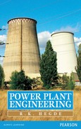
For easy, smooth and rapid operation, mechanical handling system is embraced for inplant handling of coal. A flow chart of such a system is shown in Figure 3.1. Inplant handling begins right from the coal delivery point upto the furnace firing system. The following are guidelines for an inplant coal-handling system:
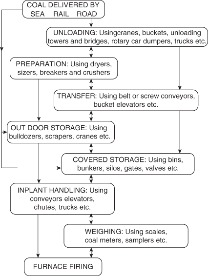
Fig. 3.1 Stages in Coal Handling
- It should be easy to handle, simple in construction and effective in working.
- For easy inspection and maintenance, it should have centralized handling units.
- It should have minimum handling operations and should be free from repetitive handling.
- The working parts should be free from erosion and corrosion.
- Its capacity should be well above the requirement of coal during peak hours.
3.1.4 Inplant Handling System
This system feeds coal from live storage to the furnace using similar equipments as explained above. Coal delivered to the plant site is weighed on wagon balance and then delivered to underground hoppers or bunkers either manually or mechanically. The coal is now lifted to the transfer tower and then to the crusher through magnetic separators and screens. Coal is crushed to the required size (20–30 mm for stoker firing and 10–20 mm for pulverized fuel firing). In the case of pulverized firing, coal is further crushed into fine powder in mill and then carried to the transfer tower from where it is conveyed to a boiler bunker. From the boiler bunker, coal now flows by gravity to boiler hopper and ultimately to the boiler furnace. Depending on the load, fuel flow is regulated by using gates and valves in the system.
3.1.5 Stages of Coal Handling
The various stages of coal handling are shown in Figure 3.2.

Fig. 3.2 Inplant Handling System
1. Unloading
Depending on the mode of transport, namely, by sea or road or rail, coal unloading is done using the following equipments:
Coal towers, unloading bridges and self-unloading boats are used if the outplant handling of coal is by sea or river.
Car shakers, rotary car dumpers and coal accelerators are used if the mode of transport is by rail.
Lift trucks with scoop are used to unload the coal if the mode of transport is by road.
2. Coal preparation
Since coal is not properly sized initially, a coal preparation plant is needed to get the uniform size of the coal before it is fed to the plant. The preparation plants consist of the following equipments:
(i) Coal crusher
The function of the coal crusher is to crush the coal to uniform size (about 8–25 mm). The capacity of the unit depends on the size of the plant.
(ii) Sizer
The function of the sizer is to pick the coal of required size, which is coming from the crusher. The unsized coal is fed back to the crusher.
(iii) Dryer
The function of the dryer is to remove excess moisture present in the coal. The moisture is removed by passing hot flue gases through the cold storage in closed spaces.
(iv) Magnetic separator
The function of the separator is to remove iron particles, which otherwise may choke the burners besides damaging other equipments. The iron particles are trapped by the magnetic pulley while the belt carrying coal passes over it. It is collected in a chute.
A typical sketch of a coal preparation plant is shown in Figure 3.3.

Fig. 3.3 Coal Preparation Plant
3. Transfer of coal
Coal transfer includes transferring of coal from unloading point to the storage site using the coal-handling equipments.
3.2 CHOICE OF HANDLING EQUIPMENT
Many coal-handling equipments are available, the choice of which depends on various considerations. Coal transfer from unloading point to the storage site can be done using the following equipments:
1. Bucket elevators
Figure 3.4 shows centrifugal and continuous types of bucket elevators used for lifting coal to moderate heights (about 30 m). It consists of buckets fixed to a chain moving over two sprockets. The buckets carry coal from the bottom and discharge to the top at a speed ranging between 15 and 36 m/min. The continuous type of elevator is used to convey more amount of coal.
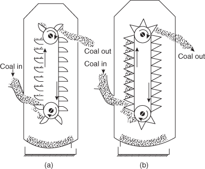
Fig. 3.4 Bucket Elevators: (a) Centrifugal; (b) Continuous
2. Grab bucket conveyor
Figure 3.5 shows a grab bucket conveyor that can grab as well as convey coal from one place to another. It is used with a crane or tower and it has different capacities. It is very essential when all other means of transporting coal are not viable. It has high initial cost but low operating cost.

Fig. 3.5 Grab Bucket Conveyor
3. Belt conveyor
Figure 3.6 shows section through a belt conveyer used for transporting large quantities of coal over long distances. It consists of an endless belt made of rubber, balata or canvas running over pulleys or end drums. The belt is supported by a series of rollers known as idlers at regular intervals. The empty belt is supported by return rollers as shown. These conveyers can be used with inclination up to 20° to the horizontal moving at an average speed of 60–90 m/min. Upto 50–100 t/h of the load can be carried over a distance of about 500 m.
Fig. 3.6 Belt Conveyer
It is an economical means of coal transportation at a rapid rate with minimum maintenance cost. By providing overhead covers, coal can be protected by rain, wind, etc. However, it cannot be used for carrying coal at greater heights.
4. Screw conveyor
Figure 3.7 shows a screw conveyer used to transmit coal. It consists of an endless helicoid screw of diameter 150–500 mm wound around a rotating shaft. One end of the shaft is connected to the drive, whereas the other end is supported by a bearing. The screw along with the shaft rotates at about 60–120 rpm and carries coal from one end to another. Screw conveyors are designed to suit different load capacities.

Fig. 3.7 Screw Conveyor
5. Flight or scraper conveyers
Figure 3.8 shows a flight conveyer used for filling a large number of storage bins situated under the conveyor. It consists of steel scrapers attached to chain mechanism. Steel scrapers scrap the coal through a trough and discharge it at the bottom in to storage bin. Due to excessive wear and tear of the scrapers, this conveyor has shorter life span.

Fig. 3.8 Scraper Conveyor
3.3 FUEL BURNING
One of the most important factors in the economical working of a power plant is the efficient combustion of fuel. Two commonly used methods for burning the fuel are stoker firing and pulverized fuel firing.
Methods of fuel firing: The solid fuels are fired into the furnace by the following methods:
- Hand firing
- Mechanical firing
1. Hand firing
This is a simple method of firing coal into the furnace. It requires no capital cost.
2. Mechanical (stoker) firing
This is used in medium- and large-size power plants. Operating cost is high.
3.3.1 Overfeed and Underfeed Fuel Bed Stokers
Stoker is a power-operated fuel feeding mechanism. The working of different types of stokers is based on the following two principles:
1. Overfeed principle
Figure 3.9 shows the operating principle of an overfeed stoker. The primary air enters the grate from the bottom. The air while moving through the grate openings gets and picks up additional energy. The air then passes through a layer of incandescent coke where O2 reacts to form CO2 and H2O vapour reacts with coke to form CO2, CO and free H2. The gases leaving the incandescent coke consist of CO2, CO, H2, N2 and H2O and volatile matter of raw fuel. Then additional air known as secondary air is supplied to burn the combustible gases. The combustion of gases entering the combustor is not complete. The combustion of the remaining combustible gases is completed in the combustion chamber. A schematic diagram of an overfeed stoker is shown in Figure 3.10.

Fig. 3.9 Overfeed Stoker Principle

Fig. 3.10 Schematic of an Overfeed Stoker
The advantages and disadvantages of this stoker are as shown below:
Advantages
- The clinkering difficulties are reduced even with coals having high clinkering tendencies, by the spreading action.
- A wide variety of coal varying from lignite to semi-anthracite as well as high ash coal can be burnt easily.
- The coking tendency of the coal is reduced before it reaches the grate by the release of volatile gases, which burn in suspension.
- It gives quick response to load change similar to pulverized fuel system because there is only a small amount of fuel on the grate at any time and most of the heat is released during burning of the coal in suspension.
- The use of high-temperature preheated air is possible.
- This form of fixing provides thin and even fire bed and results in a high rate of combustion (350 kg/m2 h). Therefore, it gives quick response of the load change and with less sensitivity to the swelling characteristics of the fuel.
- Its operation cost is considerably low, as 0.6 kW/h fired.
- Due to fire bed equal pressure drop and proper air distribution, combustion can be completed with minimum quantity of excess air.
Disadvantages
- It is always difficult to operate spreader with varying sizes of a coal and with varying moisture content.
- A natural result of suspension burning of fine fuel particles is the entrainment of ash in the products of combustion. To avoid the nuisance of fly ash, a dust collector is essential with this stoker.
- Many fine unburnt carbon particles are also carried with the exhaust gases, and it is necessary to trap these and return to the furnace for burning. Otherwise, it would add as a loss to the combustion system.
2. Underfeed principle
Figure 3.11 shows underfeed principle. In this case, air entering through the holes in the grate comes in contact with the volatile matter in raw coal is given off of by distillation. Then it passes through the incandescent coke where reactions similar to overfeed stoker take place. The gases produced then pass through a layer of ash. The secondary air is supplied to burn the combustible gases. The advantages and disadvantages of the underfeed stokers. Figure 3.12 shows a schematic diagram of an overfeed stoker.

Fig. 3.11 Underfeed Stoker Principle
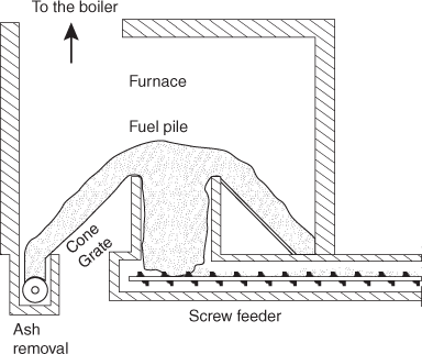
Fig. 3.12 Schematic of an Underfeed Stoker
Advantages
- This gives higher thermal efficiency compared with chain grate stokers.
- The part load efficiency is high with multiple retort stoker.
- The combustion rate is considerably higher.
- Sufficient amount of coal always remains on the grate so that the combustion is continued in the event of temporary breakdown of the coal supply system.
- The grate is self-cleaning.
- Different varieties of coals can be used with this type of stoker.
- Tuyeres, grate bars and retorts are not subjected to high temperature; they remain always in contact with fresh coal.
- The use of forced draft and relatively large quantities of fuel on the stoker make them responsive to rapid changes in load.
- (ix) The coal is continuously agitated by the plunger and pusher plates and due to this, the fuel bed remains porous and free from clinkers.
- (x) Smokeless operation is possible even at very light load.
- (xi) It can be used with all refractory furnaces because of non-exposure of stoker mechanism to the furnace. Under the existing conditions in the furnace of this type, it would not be possible to use other types.
- (xii) Underfeed stokers are suitable for non-clinkering high volatile and low ash content coals.
Disadvantages
- The initial cost of the unit is high.
- It requires large building space.
- The clinker troubles are usually present.
- Low-grade fuels with high ash content cannot burn economically. The anthracite coals with relative low ash fusion temperatures are not suited to the underfeed stoker.
3.4 EQUIPMENT FOR BURNING COAL IN LUMP FORM
Figure 3.13 shows how stokers based on the above principles can be further classified.

Fig. 3.13 Types of Stokers
3.4.1 Chain Grate Stoker
Chain grate stoker consists of an endless chain, which forms a support for the fuel bed. The chain travels over two sprocket wheels one at the front and one at the rear of the furnace. The chain receives coal at its front through a hopper and carries it into the furnace. The ash is carried over the rear end of the stoker and deposited in the ash pit. The air enters through the air inlets situated below the grate. Initial cost is high and operations and maintenance cost are low.
3.4.2 Travelling Grate Stoker
It differs from chain grate stoker only in grate construction. It carries small grate bars, which actually support the fuel bed.
The stokers are suitable for low ratings because the fuel must be burnt before it reaches the rear of the furnace.
The travelling stoker may be chain grate type or bar grate type. These two differ only in the details of grate construction. The grate surface of a bar grate stoker is made of a series of cast iron sections mounted on carrier bars. The carrier bar rides on two endless-type drive chains.
A travelling-type chain grate is shown in Figure 3.14. The chain grate stoker consists of an endless chain that forms a support for the fuel bed. The chain travels over two sprocket wheels: one at the front and other at the rear of furnace as shown in figure. The front sprocket is connected to a variable speed drive mechanism.
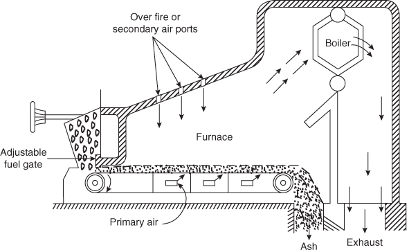
Fig. 3.14 Travelling Chain Grate Stoker
The coal is fed by gravity from a hopper located in front of the stoker. The depth of the fuel on the grate is regulated by a hand-adjusted gate as shown in figure. The speed of the grate varies at the rate at which the coal is fed to the furnace. The combustion control automatically regulates the speed of the grate to maintain the required steam generation rate. The ash containing a small amount of combustible material is carried over the rear end of the stoker and deposited in the ash pit as shown in Figure 3.14.
The air required for combustion is supplied through the air inlets situated below the grate. The secondary air is supplied through the openings provided in the furnace well above the grate. The combination of primary air and overfire air supplied provide turbulence required for rapid combustion. The primary air is brought in from the sides and then forced through the upper grate. The air-ducts under the stoker are divided into sections. The air supply to different parts of the stoker is regulated to meet the changing demand through these sections. The air openings in the grate depend on the kind of coal burned and vary from 20 to 40 per cent of the total grate area. Air dampers are provided to control air supply to the various zones. The operator controls the rate of burning in different zones to minimize the coke carried over into the ash pit, or coal supplied to the grate is regulated by varying either the depth of coal on the grate with the help of grate valve or the rate of grate travel. These grates are suitable for low rating of fuel because the fuel must be burnt before it reaches the rear end of the furnace. The rate of burning with this stoker is 200–300 kg/m2/h when forced drought is used. Any type of fuel except caking bituminous coal can be used with chain grate stoker because of the formation of large percentage of fine particles resulting in increased carbon loss.
The advantages and disadvantages of chain grate stoker are listed below:
Advantages
- It is simple in construction and its initial cost is low.
- It is more reliable in service, therefore maintenance charges are low.
- It gives high heat release rates per unit volume of the furnace.
- The heat release rates can be controlled just by controlling the speed of chain.
- It is self-cleaning stoker.
Disadvantages
- The amount of coal carried on the grate is small as the increase in grate size creates additional problems. This cannot be used for high-capacity boilers 200 t/h or more.
- The temperature of preheated air is limited to 180°C.
- The clinker troubles are very common.
- Ignition arches are required.
- There is always some loss of coal in the form of fine particles carried with the ashes.
3.4.3 Spreader Stoker
Figure 3.15 shows a spreader stoker. This is an overfeed-type stoker. The coal burns on this stoker remains partly in suspension and partly on the grate as shown in Figure 3.15.

Fig. 3.15 Spreader Stoker
In this stoker, coal from the hopper is fed on to a feeder, which measures the coal in accordance to the requirements. Feeder is a rotating drum fitted with blades. From the feeder the end drops on to spreader or distributor, which spreads the coal over the furnace. The spreader stoker distributes the coal evenly over the entire grate area. The spreader speed depends on the size of coal.
The spreader stoker consists of variable feeding device, a mechanism for throwing the coal uniformly on the grate and suitable openings for admitting the air. The coal feeding and distributing mechanism is located in the front wall above the grate. A portion of coal supplied containing fine particles of coal burns in suspension and remaining falls to the grate. The air supplied by FD fan enters the furnace through the openings provided in the grate. A portion of this air is used to burn the fuel on the grate and the remaining air is utilized to burn the volatile matter and fine particles in suspension. Overfire or secondary air is supplied through the nozzle. The secondary air creates high turbulence and completes the combustion of volatile matter and fine particles of the coal. The unburnt coal and ash are deposited on the grate, which should be removed periodically.
The feeder is a slow-speed rotating drum on which a large number of small blades is mounted. It supplies coal to the spreaders in a continuous stream. The speed of the feeder can be adjusted as per the load on the plant. The feeders are operated with variable speed drive to control the combustion as per requirement. The feeders may be reciprocating ram, endless belt or spiral worm.
The spreader consists of a rapidly rotating shaft carrying blades. These blades are twisted to provide uniform distribution of the coal over the grate. The fast rotating blades hit the coal particles coming from the feeder and throw it into the furnace. The distribution of coal over the grate depends on the rotating speed of the spreader and on the size of the coal. Variations in performance of the spreader due to the changes in coal size and moisture content can be done by means of an external hand adjustment of the mechanism.
The selection of the size of the coal used in spreader stoker should be in between 6 and 36 cm. Stationary grates are used up to 10 MW capacity plant while moving grates are used in the range of 10–30 MW capacity plant.
The spreader stoker has wide applications with respect to the fuels used as well as to the boiler sizes. A wide variety and poor quality coal can be burnt efficiently with this type of stoker. This type of stoker can be used for boiler capacities from 80 to 150 tons of steam per hour. The heat release rate of 40 × 106 kJ/m2 h is possible with stationary grate and 80 × 106 kJ/m2 h is possible with travelling grate.
Advantages
- A wide variety of coal varying from lignite to semi-anthracite as well as high ash coal can be burnt easily.
- The clinkering problems are reduced even with coals that have high clinkering tendencies due to the spreading action.
- The high-temperature preheated air can be used.
- The coking tendency of the coal is reduced before it reaches the grate by the release of volatile gases, which burn in suspension.
- This system provides thin and even fire bed and results in high rate of combustion (350 kg/m2 h) giving quick response to the load change and with less sensitivity to the swelling characteristics of the fuel.
- It gives quick response to load change similar to pulverized fuel system due to small amount of fuel on the grate at any time and most of heat is released during burning of the coal in suspension.
- The fire bed gives equal pressure drop and proper air distribution so that combustion can be completed with minimum quantity of excess air.
- Its operation cost is considerably low.
Disadvantages
- It is difficult to operate the system with varying sizes of coal and with varying moisture content.
- Due to suspension, burning of fine fuel particles is the entrainment of ash in the products of combustion; a dust collector is necessary with this stoker.
- Many fine unburnt carbon particles are also carried with the exhaust gases resulting in a loss to the combustion system.
3.4.4 Retort Stoker
In underfeed stokers, the fuel is fed from underneath the fire and moves gradually upwards. The primary air is supplied from below where combustion takes place. The fuel releases the volatile matter as it passes through the initial fuel bed from bottom. The released volatile matter mixes with fresh air and enters into the combustion zone. The entire combustion process is highly efficient and gives high rates of heat release. Bituminous and semi-bituminous coals with small ash content and fusing temperature above 1300°C (caking or non-caking) can be burnt very effectively using these stokers.
The underfeed stokers can be divided into the following two main types:
- Single retort stoker
- Multi-retort stoker
1. Single retort stoker
Figure 3.16 shows the arrangement of a single retort stoker. The fuel is placed on a large hopper on the front of the furnace. Then it is further fed by reciprocating ram or screw conveyor into the bottom of the horizontal trough. The air is supplied through the tuyeres provided along the upper edge of the grate. The ash and clinkers are collected on the ash plate provided with dumping arrangement. The coal-feeding capacity of a single retort stoker varies from 100 to 2000 kg/h.
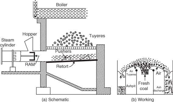
Fig. 3.16 Single Retort Stoker
Due to the inability of obtaining even air distribution from the sides of retorts, multi-retort stokers are generally used for increasing the burning capacity of the stoker.
2. Multi-retort stoker
The multi-retort stoker is shown in Figure 3.17. It consists of a series of alternate retorts and tuyere boxes for supply of air. Each retort is fitted with a reciprocating ram for feeding and pusher plates for the uniform distribution of coal. The coal falling from the hopper is pushed forward during the inward stroke ram. Then the distributing rams (pushers) push the entire coal down the length of the stoker. The ash formed is collected at the other end as shown in figure. The number of retorts may vary from 2 to 20 with local burning capacity ranging from 300 to 2000 kg/h/retort.
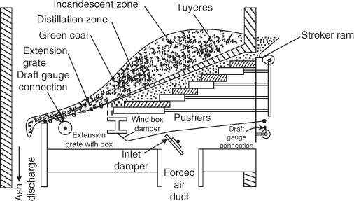
Fig. 3.17 Multi-Retort Stoker
Underfeed stokers use forced draft for maintaining sufficient air flow through the fuel bed. The primary air is supplied from main wind box to the fuel bed situated below the stoker. The partly burnt coal moves on to the extension grate. The low-pressure air enters into the extension grate and wind from main wind box is supplied to the thinner fuel bed on the extension grate. The quantity supplied can be regulated by an air damper. The air pressure in the main wind box under the stoker is also varied to meet variable load. Provision is also made for varying the air pressure under the different sections of the stoker in order to correct for irregular fuel-bed conditions. Forced draft causes rapid combustion. It is also necessary to introduce ‘overfire air’ when high volatile coals are used to prevent the smoke formation. Combustion control is introduced into the stoker drive by either varying the ram stoke or changing the rate of reciprocation. On–off control is used on motor-driven stokers.
3.5 ADVANTAGES AND DISADVANTAGES OF STOKER FIRING OVER PULVERIZED SYSTEM OF FIRING
Advantages
- There is no necessity of coal preparation plant as the coal obtained from mines can be directly used. Sometimes it is necessary to size (crush) the coal in order to suit the furnace conditions.
- This can be used for medium capacity plant more economically.
- It is free from danger of explosion.
- The building space requirement compared with pulverized system is less.
- The capital investment as compared to pulverized system is less.
- The maintenance and operating costs are less.
- The auxiliary plant required is considerably reduced.
- It also works for few hours in the event of coal-handling plant failure as large amounts of coal are stored on the grate.
- The dust collection problems are less severe compared with pulverized system as most of the ash is removed from the grate.
- The stoker firing systems are more reliable.
Disadvantages
- The loss of coal is more through riddling.
- There is heavy wear and tear of moving parts due to abrasive action of coal.
- The troubles of clinkering of combustion chamber walls are very common.
- The sudden variations of load cannot be met to the same degree of efficiency as in the case of pulverized fuel firing.
- The furnaces need fire arches, which increase the construction cost and create troubles during operation.
- Standby losses are considerably more.
3.6 PREPARATION AND BURNING OF PULVERIZED COAL
Coal is pulverized (powdered) to increase its surface exposure thereby permitting rapid combustion. Coal is reduced to a fine powder in grinding mill or pulverizers.
There are two methods used to feed pulverized fuel to the furnace.
3.6.1 Unit or Direct System
Figure 3.18 shows the schematic diagram of a unit system. In the unit system, a separate pulverizing unit is provided for each furnace and the fuel is fired directly into the furnace without being stored. The raw coal from overhand coal bunker falls into a feeder and there it is dried by supplying hot air. The coal is then transferred to the pulverizing mill where it is pulverized. Primary air is supplied to the mill by the fan. The mixture of pulverized coal and primary air then flows to burner where secondary air is added.

Fig. 3.18 Unit System
Advantages
- System is simple and cheaper.
- Direct control of combustion from pulverizing mill is possible.
- Coal transportation system is simple.
Disadvantages
- Mill operates at variable load.
- System is less flexible.
- No reserve.
- Fan handles air + coal mixture.
3.6.2 Bin or Central System
Figure 3.19 shows the schematic diagram of a bin system. In central system, the coal is ground in a central grinding plant and stored in bins or bunkers. From the bunkers it is distributed in various burners through separate feeders in accordance with load demands.
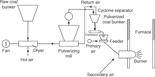
Fig. 3.19 Bin System
Coal from the raw coal bunker is fed by gravity to a dryer where it is dried by the hot air mill. The pulverized coal from the mill is transferred to pulverized coal bunker. The air from the coal is separated in the cyclone separator and returned to the mill. The primary air is mixed at the feeder and the mixture is supplied to the burner.
Advantages
- Pulverizing mill grinds the coal at steady rates irrespective of the load.
- There is always some coal in reserve. Thus, failure of the mill will not affect the coal fed to the burner.
- Exhaust fan handles clean air.
- For a given boiler capacity, pulverizing mill of smaller capacity will be required.
Disadvantages
- Initial cost of the system is high.
- Coal transportation system is complicated.
- System requires more space.
3.6.3 Advantages and Disadvantages of Pulverized Coal Burning
The advantages and disadvantages of pulverized coal burning are as follows:
Advantages
- By breaking, a given mass of coal into smaller pieces exposes more coal surface area for combustion. The increase of surface area exposed per unit volume with the decreasing diameter of coal particle is shown in Figure 3.20. This increase varies rapidly after 0.01 inch diameter of the coal particle and there is no substantial increase after 0.001 inch diameter.
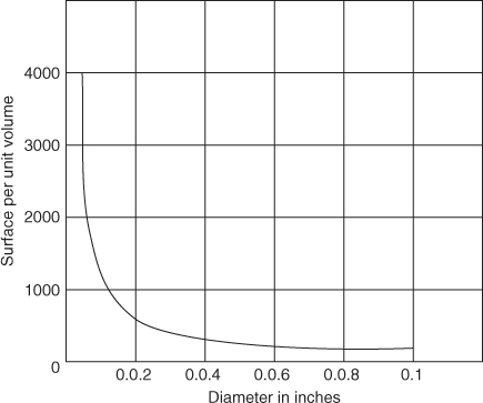
Fig. 3.20 Surface Area versus Coal Size
- Greater surface area of coal per unit mass of coal allows faster combustion as more coal surface is exposed to heat and oxygen. This reduces the excess air required to ensure complete combustion and the fan power also.
- The system is perfectly free from clinker and slagging problem.
- This system works successfully with or in combination with gas and oil.
- Large amount of heat release is possible and with such rate of heat generation; each boiler of pulverized fuel-fired system can generate as large as 2000 tons of steam per hour.
- Wide variety and low-grade coal can be burnt more easily.
- It gives fast response to load changes as rate of combustion can be controlled easily and immediately. Automatic control applied to pulverized fuel-fired boilers is effective in maintaining an almost constant steam pressure under wide load variations.
- The external heating surfaces are free from corrosion and fouling as smokeless combustion is possible.
- The banking losses are low compared with stoker firing system.
- The boilers can be started from cold very rapidly and efficiently.
- Practically no ash-handling problems exist.
- It is possible to use highly preheated secondary air (350°C), which helps in rapid flame propagation.
- (xiii) The pulverizing system can be repaired without cooling the unit as the equipment is located outside the furnace.
- (xiv) The furnace volume required is considerably less as the use of burners, which produce turbulence in the furnace, makes it possible to complete combustion with minimum travel of flame length.
- (xv) Rate of feed of the fuel can be regulated.
- (xvi) The smaller quantity of excess air and thorough mixing of air and fuel produce a high furnace temperature with little smoke.
- (xvii) The system can withstand high combustion air temperature.
- (xviii) The life of the system is more and the operation is less troublesome due to the absence of moving parts in the furnace.
Disadvantages
- As additional equipment is essential to pulverize the coal, the initial cost is more.
- Pulverized coal firing produces fly ash, which requires separate fly ash removal equipment.
- The furnace has to be designed to withstand high temperature.
- There will be a chance of explosion.
- Special equipment is required for starting the system.
3.7 PULVERIZED FUEL FURNACES (BURNERS)
Burners are used to burn the pulverized coal. The pulverized coal burners should satisfy the following requirements:
- It should mix the coal and primary air thoroughly and project the same in the furnace with secondary air.
- It should create proper circulation and maintain stable combustion of coal.
- It should control the flame shape and its travel in the furnace.
- The mixture of coal and air should move away from the burner at a rate equal to flame travel in order to avoid the flash back with the burner.
- The burner should avoid overheating, internal fires and excessive abrasive wear.
3.8 PULVERIZED MILLS
There are various types of mills used for pulverizing the coal. These are:
- Ball mill
- Ball and Race mill
- Impact or Hammer mill
- Bowl mill
1. Ball mill
The ball mill shown in Figure 3.21 consists of a large cylinder partly filled with various sized steel balls (2.5–5 cm in diameter). Coal (6 mm) is fed into the cylinder that mixes with these balls. Pulverization takes place as a result of action between the balls and the coal, as the cylinder is rotated (130 m/min peripheral velocity).

Fig. 3.21 Double Classifier Ball Mill
The mill consists of coal feeder, pulverizer, classifier and exhauster. The feeders supply coal to the classifier, which is further passed to the pulverizer with the help of screw conveyor. A mixture of tempering air and hot air from air-preheater is introduced in the pulverizer. These streams of air carry the pulverized coal and pass through the classifier. The oversized particles are thrown out of the air stream in the classifier and fine material is passed to the burner through exhaust fan.
The output of the mill can be controlled by the dampers located in the exhaust fan inlet duct. These dampers vary the flow of air through the mill, thus controlling the rate of fuel removed from the mill. The dampers are operated by the boiler's automatic combustion control. The feeder output is regulated by the coal level in the cylinder. When coal level in the cylinder attains sufficient height to seal off the lower channel, the differential control operates to stop the coal feed.
A ball mill capable of pulverizing 10 tons of coal per hour containing 4 per cent moisture requires 28 tons of steel balls and consumes 20–25 kW hour energy per ton of coal.
The principal features of this pulverizer are:
- The grinding elements are not seriously affected by metal scrap and other foreign material in the coal unlike the grinders in most other pulverizers.
- There is considerable quantity of coal, which acts as a reservoir. This pulverizer prevents the fire from going out when there is slight interruption in fuel feed caused by coal clogging in the bunker.
- A wide range of fuels including anthracite and bituminous coal, which are difficult to pulverize, can be used in this mill.
- The system is simple to operate, low in initial cost but has high operating cost.
2. Ball and race mill
This is also known as contact mill. It consists of two elements that have a rolling action with respect to each other. The coal passes between the rotating elements time and again until it has been pulverized to the desired degree of fineness. The pulverization is completed by a combination of crushing impact and attrition between grinding surfaces. The coal is crushed between two moving surfaces: balls and races. The upper stationary race and lower rotating race driven by a worm and gear hold the balls between them. The coal is supplied through the rotating race driven by a worm and gear, and hold the balls between them. The coal is supplied through the rotating table feeder at the upper right to fall on the inner side of the races. The moving balls and races trap coal between them to crush it to powder. Spring hold down the upper stationary race and adjust the force needed for crushing.
A forced draft fan supplies hot air to the mill through the annular space surrounding the races. The air picks up the coal dust as it flows between the balls and races and then enters into the classifier above. The fixed vanes make the entering air to form a cyclonic flow throwing the oversized particles to the wall of the classifier. The oversized particles slide down for further grinding in the mill. The coal particles of required size are taken to the burners with air from the top of the classifier. A typical Ball and Race mill is shown in Figure 3.22.

Fig. 3.22 Ball and Race Mill
The mill is provided with a means of separating heavy impurities from the coal and thus reducing wear and possible damage to the grinding element. These heavy particles resist the upward thrust caused by the primary air stream and collect in a compartment in the base of mill, and then they are removed periodically. The automatic combustion control regulates the flow of primary air through the pulverizer and feeder and maintains the coal supply. When more coal is required, the primary air flow is increased automatically and its higher velocity in the mill carries additional coal in the furnace. This action reduces the amount of coal in the pulverizer and decreases the pressure drop, thus causing the feeder controller to supply more coal.
The fan used with this mill handles only air, therefore the blade erosion by coal particles is eliminated. As the casing of the pulverizer is under pressure, the leakage of fine coal through the mill casing causes the pulverized fuel to be blown out into the boiler room. This mill can handle coals containing as much as 20 per cent moisture. Mill, feeder and fan need nearly 15 kW hour energy per ton of coal pulverized.
Advantages and disadvantages
These pulverizers have greater wear compared to other pulverizers. However, the following advantages have outweighed the wear problem and these pulverizers have found general acceptance.
Advantages
- lower space is occupied
- lower power consumptions in kW h/ton of coal pulverized
- lower weight and lower capital cost
3. Impact or hammer mill
This is also known as impact mill as pulverization takes place by impact. The coal in pulverizer remains in suspension during the entire pulverizing process. All the grinding elements and the primary air fan are mounted on a single shaft as shown in Figure 3.23. The primary air fan induces flow of air through the pulverizer carrying the coal to the primary stage of grinding. In the primary stage of grinding, the coal is reduced to fine granular state by impact with a series of hammers and then into the final stage where pulverization is completed by attrition. The final stage of grinding consists of pegs carried on a rotating disk and travelling between stationary pegs. The finely pulverized coal in the final stage of grinding is carried with the air to the burner through the rotating scoop-shaped rejecter arms, which throw the large particles back into the grinding section.
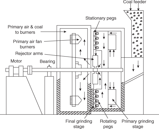
Fig. 3.23 Impact Mill
The output of the pulverizer is controlled by varying the coal feed and the flow of primary air by either hand or automatic control.
Advantages
- The pulverizer is directly connected to the motor drive and therefore operates at high speed.
- The power required to drive the pulverizer is nearly proportional to the coal pulverized over a wide range of rating.
- This mill requires minimum floor area due to high speed of the pulverizer and the fan being integral with the pulverizer.
4. Bowl mill
The bowl mill shown in Figure 3.24 consists of stationary rollers and a power-driven bowl in which pulverization takes place as the coal passes between the sides of the bowl and the rollers. A primary air-induced draught fan draws a stream of heated air through the mill, carrying the pulverized coal into a stationary classifier located at the top of the pulverizer. The classifier returns the coarse particles of coal to the bowl for further grinding through the centre cone of the classifier. The coal pulverized to the desired fineness is carried to the burner through the fan. The impurities in coal containing heavy particles are thrown over the side by centrifugal force as these enter the rotating bowl. The heavy particles thrown out fall into the space below the bowl. These are discharged from the mill through a spout. The automatic control charges the supply of coal to the bowl to the mill by adjusting the feeder speed and the flow of primary air by regulating the damper in the line from the pulverizer to the fan.

Fig. 3.24 Bowl Mill
Some features of this pulverizer are:
- Classifier may be adjusted to change the coal fineness while the pulverizer is operating.
- Leakage of coal from the mill casing is completely eliminated as the mill operates under negative pressure.
Selection of the bowl mill is based on the following of parameters:
- Total moisture content, used to determine the mill drying capacity.
- Sulphur and mineral content, used to determine pyrite removal sizing requirements.
- Grindability, used to select the mill size.
- Volatile matter, used to determine the required coal fineness.
- Higher heating value of the coal, which affects the ability of a pulverizer to meet the boiler requirement for maximum continuous rating.
A typical modern pulverizer can grind most of the fuel to at least 98–99 per cent passing 50 mesh and 60–70 per cent passing 200 mesh. The capacity of the pulverizer is also dependent on the raw coal feed size, grindability, moisture content and fineness required of the final coal.
3.8.1 Causes for Mill Fires
Mill fires are most often caused due to the following reasons:
- Pyrite building from pyrite plow failure
- Hot start up with loaded mill
- Accumulation of coal dust in mill devices
- Localized hot spots from poor primary air flow
The causes of fires are also dependent on coal properties (volatile matter and moisture) that exceed pulverizing rating. Wet coal always blocks feeders, reduces system input and produces very lean fuel–air mixture in the mill. Better coal-handling method and effective trash separation could reduce feeder problems and the likelihood of mill fire. Closing of the multiport outlet valve can prevent the spread of fire from mill to burner lines. Three major types of quenching methods used are water, steam and CO2 injection. Use of water has proved inadequate in some deep-seated mill fires. Steam injection is effective but explosive CO–H2 mixture may result from steam coke reaction.
3.9 FUEL-BURNING EQUIPMENTS
Different types of fuel burners are used to burn solid, liquid and gaseous fuels. Solid fuel mainly used is pulverized coal. Liquid fuels are burnt in oil burners, whereas gaseous fuels are burnt in gas burners.
3.9.1 Coal Burners
The function of the coal burners is to burn pulverized coal in the presence of primary and secondary air in a boiler furnace. Coal burners are classified according to their design and arrangement in the furnace. The following types of coal burners are used in practice:
1. Stream-line burner
It is also known as long-flame or U-flame burner. It is designed to fire downwards in the furnace without any turbulence. Thin flat streams of air and fuel mixture are discharged in the furnace, which travel a considerably long distance producing a long flame and ensuring complete combustion. Heated secondary air, which is fed at right angles to the flame, ensures proper mixing of air and fuel. This type of burner is suitable for burning fuels with low volatile matter as fuel flows at low velocity (15–45 m/s) and hence takes more time to travel in the furnace (Figure 3.25). A U-flame burner is shown in Figure 3.25.

Fig. 3.25 U-Flame Burner
2. Turbulent burner
Schematic of a tangential burner is shown in Figure 3.26. It is made up of circular discharge orifices or with straight narrow outlets. It is placed in the wall of water-cooled furnaces. The fuel and air mixture pass through the burner such that they mix properly at the furnace entrance. Fuel burns in the furnace producing a short turbulent flame. These burners are very useful to burn high volatile matter fuels.

Fig. 3.26 Turbulent Burner
3. Tangential burner
In tangential burners, fuel and air streams are ejected in a horizontal direction tangent to an imaginary circle at the centre of the furnace. The burners are placed at the corners of the furnace to ensure intense turbulence and thorough mixing of fuel and air. All the fuel and air nozzles can be fitted at an angle of 20–25° above and below the horizontal plane. Schematic of a tangential burner is shown in Figure 3.27.

Fig. 3.27 Tangential Burner
4. Cyclone burner
Cyclone burners are used to burn crushed coal instead of pulverized coal. This is to eliminate fly ash-handling problems. It consists of a cyclone furnace as shown in Figure 3.28. Crushed coal of about 8 mm size is fed from the feeder to the centre of the cyclone along with primary air. This creates a vortex flow in the furnace. The secondary air is supplied separately to increase the vortex flow. The ash formed due to rapid burning of coal drains down the inner wall of the furnace as molten slag. Hot flue gases along with 10–20 per cent of fly ash enter the furnace. Due to centrifugal action most of the fly ash is thrown against the furnace wall and is drained out along with molten slag. Thus, flue gases leaving the furnace are clean.
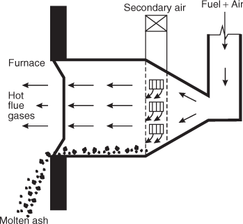
Fig. 3.28 Cyclone Burner
A schematic diagram of a cyclone furnace showing the circulation of primary, secondary and tertiary air is shown in Figure 3.29 below.

Fig. 3.29 Schematic Diagram of a Cyclone Furnace
3.9.2 Oil Burners
Oil burners can be classified into two different types, namely, (i) vapourizing type and (ii) atomizing type.
The vapourizing burners are used for domestic purpose especially in portable air heaters, cooking stoves, etc. The atomizing burners are commonly used in industrial heating.
1. Vapourizing burner
Petromax stove, which burns kerosene, is a classical example of a vapourizing burner. Here, an upward moving high-velocity fuel jet is allowed to strike against hot moving plate. The vapours burn with a short intense flame. The fuel is stored in a fuel tank below the fuel line and a hand-driven piston is used to increase the oil pressure by compressing the air into the reservoir.
2. Atomizing burner
These burners are very commonly used in oil-fired furnaces of steam generators. The oil is divided into fine particles to increase the surface area of contact with the combustion air. Due to atomization, a homogeneous mixture of oil and air is produced, which is fired into the furnace. Atomization is achieved by the following two methods:
(i) Steam or air jet atomization
Steam jet atomization is used in power appliances, whereas air jet atomization is used for heating work.
(ii) Mechanical atomization
In mechanical atomization, oil is pressurized by using a positive displacement pump or a rotating wheel that displaces the oil centrifugally. It is used in high-capacity steam-generating furnaces.
Figure 3.30 shows a high pressure steam or air atomizing burner. In this burner, oil is delivered under pressure through a central tube. Steam or air is supplied along the annular space between the oil pipe and the concentric outer tube. Near the tip of the burners the two streams impinge resulting in atomization of fuel. To improve combustion efficiency and flow conditions, the viscosity of the oil is reduced by heating it to about 120°C. The heated oil is then supplied to the burner.

Fig. 3.30 Atomizing Burner
3.9.3 Gas Burners
As the fuel is readily available in vapour form, gas burners are simpler in construction. Different types of gas burners are used in practice. Figure 3.31(a) shows a ring burner that can be used to control the flame length. The rate of gas flow can be controlled by using the dampers. The gas flows through an annular ring, whereas air is induced both around and within the annular ring. Figure 3.31(b) shows a typical burner used for feeding gas and air under pressure. To prevent the back flow of flame, the velocity of the gas is set at a higher rate compared to the air velocity.

Fig. 3.31 Gas Burners
3.10 FLUE GAS ANALYSIS
The percentage by volume of carbon monoxide (CO), carbon dioxide (CO2), oxygen (O2) and nitrogen (N2) in a flue gas is determined by Orsat apparatus.
The flue gas analysis carried out by the Orsat apparatus (Figure 3.32) gives fairly accurate results upto ±0.5 per cent of CO2 content. In its simplest form, the apparatus is arranged to determine the composition of CO2, CO2, CO and N2 by difference. It contains a Eudiometer (A) graduated upto 100 cc and surrounded by water jacket. The base of the eudiometer is connected to an aspirator bottle (B) by means of a flexible rubber tube. By lowering or raising the aspirator bottle, the eudiometer can be charged or discharged. The flasks 1, 2 and 3 with duplicate flasks behind them contain KOH solution (caustic potash with KOH:H2O, 1:2 by weight) for absorbing; alkaline solution of pyrogallic acid (5 g of pyrogallic acid in 15 cc of water is mixed with 120 g of KOH in 80 cc of water) for absorbing O2; and cuprous chloride (CuO dissolved in 20 times its weight in concentrated HCl with copper wire immersed till it becomes colourless) for absorbing CO. Small glass tubes packed in the flasks 1, 2 and 3 accelerate the absorption of gases.
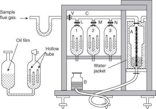
Fig. 3.32 Orsat Apparatus
3.10.1 Procedure
The chemical reagents in the flasks 1, 2 and 3 are freshly prepared and filled. The eudiometer jackets are filled with water. The aspirator bottle is filled with salt water so that water does not absorb the gases. The three way cock ‘V’ is opened to the atmosphere and the aspirator bottle is raised till the salt water level in the eudiometer tube reaches 100 cc mark and then the cock is closed. Now cock ‘L’ is opened and the aspirator bottle is lowered. The reagent in the flask 1 raises and touches the mark on the capillary tube. Cock ‘L’ is immediately closed. Due to this action, all gases including air are expelled from the flask. Same procedure is repeated with flasks 2 and 3. The aspirator bottle is now raised to expel all the gases removed from the flasks. It can be noted that the amount of gases present in the capillary tube ‘C’ is negligible.
The sample gas tube is now connected to the three-way cock and the cock is opened to the flue gases. Aspirator bottle is lowered to aspirate exactly 100 cc of sample gas (till the water level touches 0 cc mark). Cock ‘V’ is closed. To ensure no leakage, the aspirator bottle is raised again. If there is leakage, water level in the eudiometer goes on rising. The sample of gas is aspirated through a U-tube containing wool to ensure only filtered gas. The water jacket of the eudiometer ensures that all the moisture condenses and a dry sample of 100 cc gas is obtained. The aspirator bottle is now brought near the eudiometer so that the water levels in the eudiometer and the bottle remain the same. This ensures that the gas sample collected is at atmospheric pressure.
The cock ‘L’ is opened and the aspirator bottle is raised to pass the sample of gas into flask 1, which contains KOH solution. During this period, the reagent passes to the duplicate flask to accommodate the sample gas and the wetted surface of the glass tube absorbs CO2 gas. The aspirator bottle is now lowered so that the reagent rises, washing the glass tubes. The aspirator bottle is raised and lowered a few times so that all CO2 is absorbed. Cock ‘L’ is closed. The aspirator bottle is brought near the eudiometer again such that the level of water in the bottle and the eudiometer remains same. The reading on the eudiometer tube is noted, which gives percentage by volume of CO2.
The same procedure is repeated by opening cocks ‘M’ and ‘N’ one by one. The corresponding readings on the eudiometer tube give percentage by volume of oxygen (O2) and carbon monoxide (CO), respectively.
volume per cent of nitrogen (N2) is determined as follows:
volume per cent of N2 = 100 − volume per cent of (CO2 + O2 + CO)
3.11 ASH HANDLING SYSTEM
Coal that is available in nature has some percentage of ash. When coal is burnt, about 10–20 percent of it is converted into ash. Considering the large coal-burning capacity of modern power plant, the amount of ash that is produced annually accounts to thousands of tonnes per annum. Thus, it is necessary to have modern ash-handling systems.
An ash-handling system should perform the following operations in sequence as shown in Figure 3.33.
Fig. 3.33 An Ash-Handling System
Figure 3.34 shows the general layout of an ash and dust handling system used in modern power plants.

Fig. 3.34 Ash and Dust Handling System
Modern ash-handling system may be classified into the following four groups:
1. Mechanical handling system
Figure 3.35 shows a mechanical dust-handling system. This system is used to handle limited amount of ash especially in small plants. Hot ash from the boiler furnace is made to fall through a water seal over the belt conveyor. The cooled ash is carried away by the belt to the dumping site or to an overhead bunker. The ash is disposed off from the bunker by means of trucks. The system can deliver ash up to 3 t/h with a speed of 30 cm/min for a period ranging from 5 to 10 years. Power consumption using this system is low.

Fig. 3.35 Mechanical Ash-Handling System
2. Pneumatic system
Figure 3.36 shows a typical pneumatic ash-handling system. In this system, air is used as a medium to carry ash over long distances at the rate of 5–30 t/h. The system consists of ash crushers, separators, hopper and ash filter.

Fig. 3.36 A Typical Pneumatic Ash-Handling System
The ash collected in the ash hopper is crushed by using ash crushers. This ash is carried to the primary and secondary cyclone separators using air. Heavier ash settles down due to centrifugal action and is collected in the ash hopper. Air leaving the secondary separator is further cleaned by passing through filter. Clean air is exhausted to the atmosphere using exhaust fan. This system is prone to rapid wear and tear resulting in failure of conveying pipes; it is noisy in operation.
3. Hydraulic system
In this system, water is used as the medium to carry ash at high velocity through channels. Depending on water pressure or velocity, the system is subdivided as low-pressure system and high-pressure system.
(i) Low-pressure system
In this system, ash falling from the boiler furnace is carried away by water moving at a low velocity of 3–5 m/s into sumps. In the sump, ash and water are separated by passing over a screen. Water is pumped back to the trough and used again. The ash collected is removed using carriages. This system is continuous and can handle about 40–50 t/h of ash through a distance about 500 m. Figure 3.37 shows a low-pressure system.

Fig. 3.37 Low-Pressure System
(ii) High-pressure system
In high-pressure system, the hoppers below the boilers are fitted with water nozzles at the top and on the sides. Ash is quenched by top nozzle spray and is carried away by the side nozzle spray. The quenched ash flows along with water at high velocity and gets collected in the sump. Water is separated by ash by passing it over screen and is re-circulated. Figure 3.38 shows a high-pressure system.
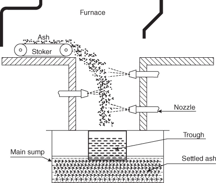
Fig. 3.38 High-Pressure System
Advantages of hydraulic system
- It is clean, dustless and totally enclosed.
- Its ash-carrying capacity is considerably large, therefore it is more suitable for large thermal power plants.
- It can discharge ash to a considerable distance (1000 m) from the power plant.
- It can also be used to handle a stream of molten ash.
- The unhealthy aspects of ordinary ash basement work are eliminated.
- The whole system is clean and healthy.
- (vii) The important feature of the system is the absence of working parts in contact with the ash.
Low-velocity hydraulic system is gaining more popularity in modern thermal power stations as it is simple, able to handle large ash quantities, and is clean and comparatively economical.
4. Steam jet system
In this system, high-pressure jet of steam is used as a medium to carry away the ash from boiler hopper. This system can remove ash through a horizontal distance of 200 m and a vertical distance of 30 m. This system is useful particularly when there is limited space so that no other handling plants can be installed. As pipes carry ash that is highly abrasive, it is necessary to use nickel alloy as lining to prevent wear and tear. This system does not require any other auxiliary drives except steam generated by the boiler itself. For each tonne of ash removal, about 110 kg of steam is required.
3.11.1 Advantages and Disadvantages of Wet and Dry Ash-Handling Systems
Advantages of wet system
- Transportation of ash by pipelines eliminates noise, dust and traffic problems.
- Use of manned equipment is eliminated.
- The system is unaffected by transportation strikes.
Disadvantages of wet system
- Large quantities of leachate under a positive pressure head in pond pose a constant threat to ground water quality. This is prevented by surface preparation and artificial lining, which are very costly.
- The transport water is normally recycled. This requires additional pipelines, pumping equipment, treatment facilities and substantial operating and maintenance costs.
- A larger area is required. Area of wet system may be twice that of the dry system.
- Water requirements are very large.
- Scaling and cementation within pipeline, particularly when the slurry contains calcium, magnesium and sulphate ashes, may render this system unsuitable in certain cases.
- It is not flexible to relocate the other discharge site.
Advantages of dry system
- Leachate quantities are significantly reduced. Liners to disposal area can be eliminated by fixation of ash. Ash piles can be designed to provide drainage at different levels.
- Water and power requirements are considerably less.
- Compacted ash is a structural material that can be sold.
- Required storage volume and area are reduced considerably. The density of compacted ash is 1400 kg/m3 against 900 kg/m3 of loose ash.
- The ash disposal site has wider choice of land after closure.
- This system offers greater flexibility in operation as ash is transported by vehicles to different sites.
Disadvantages of dry system
- Use of trucks makes this system totally dependent.
- It presents increased visual impact along transportation route.
- Wetting of ash containing calcium and magnesium forms lumps, which may stick to conveying belt.
3.12 DUST COLLECTION
The exhaust gases leaving the boiler contain fine particles of solid matter in suspension in the form of smoke, dust, soot, fly ash or cinder. The amount of these solid particles depends on the method of firing. In the case of pulverized fuel firing, about 80 per cent of total ash produced in the furnace escapes through the chimney in the form of fine particles (particulates varying from 1 to 80 μ). Such emissions from the power plant are highly objectionable considering their ill effects on environment and living things. Dust collection and removal poses a serious problem in power plants.
Dust collectors may be either mechanical or electrical type.
3.12.l Mechanical Dust Collectors
Mechanical dust collectors may be either dry or wet type. In the case of wet-type collectors, dust is washed away by spraying water on it.
1. Gravitational separators
Figure 3.39 shows different types of gravitational separators. In Figure 3.39(a), the gas velocity reduces due to increased duct area. Heavier dust particles settle at the bottom in Figure 3.39(b); the flow direction of the flow gas is suddenly changed and heavier particles settle at the bottom. In Figure 3.39(c), some baffles are placed in the direction of flow of flue gases. The dust particles strike the baffles and settle.

Fig. 3.39 Gravitational Separators
2. Cyclone separator
In a cyclone separator shown in Figure 3.40, high-velocity flue gas carrying dust is made to pass through a conical separator in a tangential direction. This results in a centrifugal action (whirling motion), throwing away the heavier dust particles to the sides of the conical chamber. Dust-free gas from the conical shell is passed through a secondary chamber to the chimney. Heavier dust particles accumulate on the inner surface of the shell and settle at the bottom. For efficient handling of dust, multiple cyclone dust collectors are used in both stoker firing and pulverized fuel firing installations.

Fig. 3.40 Cyclone Separator
3. Baghouse filters
To remove the dust particles from the flue gas, fabric filters are used in power plants. They are made of porous material that retain particulate matter as gas passes through the voids. A fabric filter element is made up of long hollow cylindrical tube that provides a large surface per unit of gas volumetric flow rate. A system consisting of a large number of such filter elements arranged in parallel rows is called a baghouse. The diameter of the hollow cylinder varies from 130 to 350 mm with height up to 12 m.
Dirty gases from the air heater enter the filter elements at the bottom and deposit the particulate matter on the inner surface of the tubes. Gases then pass laterally through the fabric and exit to the outlet manifold. The gases enter the chimney afterwards. The element has an open bottom and closed top and rests on a sheet above a dirty air plenum. The collection efficiency of such filters is about 99.99 per cent. Figure 3.41 shows a baghouse filter.
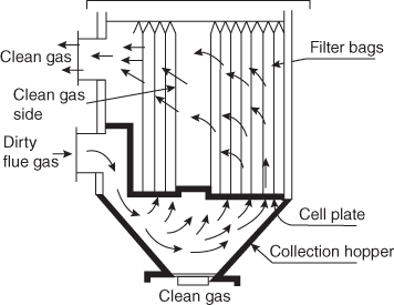
Fig. 3.41 A Baghouse Filter
4. Wet scrubber
Figure 3.42 shows principle of working of a wet-type dust collector, also known as gas scrubber. In this system, dirty flue gas enters the vertical chamber tangentially and follows a vortex path in the chamber and finally escapes out. During this period, water is being sprayed into the gas using a spray manifold placed at the centre of the chamber. The dust in the flue gas is washed off and drains in the form of slurry from the bottom. To minimize corrosion, the chamber and pipes are lined with lead and rubber, respectively. The spray nozzles are usually made of vitrified materials. The efficiency of this system is about 90 per cent, but it is susceptible to corrosion and requires a large quantity of water.

Fig. 3.42 A Wet-Type Dust Collector
3.12.2 Electrical Dust Collector (Electrostatic Precipitators)
With stringent air quality restriction by the governments, a majority of the power plants in the world use electrostatic precipitators (ESPs) for dust removal. An ESP can handle large volumes of flue gases accompanied low pressure drop and high collection efficiency (99.5 per cent). It facilitates easy removal of dust particles.
Figure 3.43 shows a general arrangement of an ESP. It consists of two sets of electrodes: the emitting or discharging electrode and collecting electrode. In the case of a tubular-type precipitator, emitting electrodes are placed in the centre of the pipe whereas in the case of plate-type precipitator, emitting electrodes are placed midway between the two plates. The emitting electrodes are connected to negative polarity of high-voltage (20–100 kV) DC source. The collecting electrodes are connected to the positive polarity of the source and earthed.

Fig. 3.43 A General Arrangement of an ESP
When high voltage is applied, it generates a unidirectional non-uniform electric field having greater magnitude at the discharge electrodes. This results in a blue luminous glow, called a corona around them. This corona is an indication of negatively charged ionized gas molecules that travel from discharge electrodes to grounded collection electrodes. The dust particles thus get deposited on the collector electrodes and lose their charge. The remaining dust particles cling to the electrode surface due to electrical resistivity, and are removed by rapping the electrodes using rapping motors.
Working principle
The principal components of ESPs are two sets of electrodes as shown in Figure 3.44. The first set comprises rows of electrically grounded vertical parallel plants, called collection electrodes. The gas to be cleaned flows between these plates. The second set, called discharge electrodes, consist of wires. These are located centrally between each pair of parallel plates. The wires carry a unidirectional, negatively charged high-voltage (between 20 and 100 kV) current from an external source. This generates a non uniform, unidirectional electric field with greater magnitude near the discharge electrodes. When the voltage is high enough, a blue luminous glow, called corona, is produced around them. It is an indication of negatively charged gas ions. These ions travel from the wires to the grounded collection electrodes due to the presence of strong electric field between them.
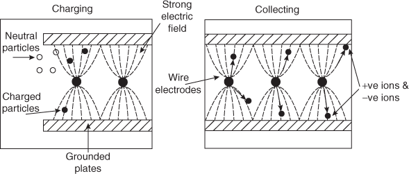
Fig. 3.44 Working Principle of ESP, Charging and Collecting
Electrical forces in the corona accelerate the free electrons present in the gas, which in turn ionize the gas molecules, forming additional electrons and positive gas ions. The new electrons in turn again ionize the gas ions and this chain reaction continues.
The +ve ions migrate to the negatively charged wire electrodes. The electrons follow the electric field towards the grounded electrodes. Their velocity decreases as they move away from corona region.
The −ve ions migrating along electric field lines collide with the particulate matter in the gas and charge them with negative potential. The particles after acquiring sufficient charge move towards the grounded electrodes.
Migration velocity is given by
Vm = 
where p = a function of particle dielectric constant
= 1.50 → 2.40
E = applied voltage, V
S = distance between charging and collecting electrodes
d = particle diameter, m
μg = gas viscosity, kg/m s
When the particles collect on the grounded plates, they lose their charge to ground. The electrical resistivity causes only partial discharging. High resistivity results in holding of charges and increases the forces holding the particles to the plates low resistivity results in quick grounding of charges and hence re-entraining of particles.
When dust builds up on the plates, it deposits in a layer of increased thickness. This results in possible re-entry into the gas stream unless periodically removed. This is done by rapping the plates so as to cause shock vibrations that shake the dust into the hoppers at the bottom of the precipitator. The discharging and rapping processs are shown in Figure 3.45

Fig. 3.45 Working Principle of ESP, Discharging and Rapping
3.12.3 Soot Blowers
The products of combustion, namely, dust, soot, particulates, fly ash, carbon ash (cinder), etc., cling to the water tubes, economizer tubes, air preheater tubes and superheater tubes. This results in reduced heat transfer and boiler efficiency. Hence, these deposits should be regularly removed for efficient working of boilers. This method of removing soot is known as soot blowing. Soot blower consists of a set of tubes fitted with nozzles carrying high-velocity jet of steam or air. In the hotter parts of the boiler, the blower advances into the furnace, cleans the heat transfer surfaces and comes back. This type of soot blower is known as retractable soot blower.
The usual form for the smaller boilers (Figure 3.46) is a dead-end tube projecting through the setting and extending into the tube bank. A number of small lateral nozzles are provided and the external head is arranged so that high-pressure steam can be admitted to the tube and at the same time the tube rotated around its axis. Externally, the device incorporates a turning mechanism (manual or motorized), a valve and the packing gland necessary between fixed steam supply and rotating tube. Steam jets clean soot from heating surface in their vicinity, but the action is limited in extent in a close array such as a tube bank; hence, several elements may be needed to clean a boiler adequately. It is quite common to see 8–16 units in a large boiler. These would be tedious to operate manually, and hence must not all be operated simultaneously; the operating heads are electric motor powered and operated by remote control on an automatic sequential basis. On some boilers, the automatic draft system controls have to be positioned for abnormally high draft before beginning the soot blowing operation; otherwise, the release of steam into the setting may blow soot and smoke into the boiler room.

Fig. 3.46 Soot Blower
When not in use the soot blower tube of the system would be dry uncooled, and subject to gas temperatures. Even with alloy tubes, the deterioration is relatively rapid on units normally experiencing high gas temperatures. Retractable elements, although more expensive initially, have the advantage of protection from high temperature when not in use. Also, using only two travelling nozzles, the jet size can be larger without excessive steam drain, and the projected blast distance greater. The eroding action of blower jets on boiler tubes, sometimes seen with the fixed rotary type, is said to be much less with the retractable type. Principal disadvantages are (i) clearances required around outside of setting and (ii) more difficult steam-packing job (travel as well as rotation). Despite the cost of compressed air, some retractable elements have been operated on air to reduce boiler water make up, and blower packing gland maintenance.
Soot blowers should be operated frequently enough to keep the tubes clean. Instead of a once a shift or twice a shift rule of thumb routine, the operating engineer should observe the flue gas temperature drop, estimate the quantity of steam per blow and calculate the frequency on an economic basis. Obviously, if the temperature drops 24°C after blowing, the interval might well be decreased, whereas if only 12°C were observed, it could represent a net loss because the value of the steam used was more than that of the increment of flue gas heat.
3.13 QUESTIONS
3.13.1 Objective Questions
- The equipment used in Orsat apparatus is
- Eudiometer
- Planimeter
- Manometer
- None
- The flue gas analysis is done by using
- Orsat apparatus
- Visometer
- Bomb calorimeter
- Junker's gas calorimeter
- In Orsat Gas Analysis, KOH solution is used for absorbing
- O2 gas
- CO2 gas
- CO gas
- H2 gas
- In Orsat Gas Analysis, alkaline solution is used for absorbing
- O2 gas
- CO2 gas
- CO gas
- H2 gas
- In Orsat Gas Analysis, cuprous chloride solution is used for absorbing
- O2 gas
- CO2 gas
- CO gas
- H2 gas
- Answers:1. a 2. a 3. b 4. a 5. c
3.13.2 Review Questions
- Write a short note on the following.
- Coal burners
- Oil burners
- Gas burners
- What are the merits and demerits of pulverized coal?
- Explain with a neat sketch the working principle of double classifier ball mill.
- What are the principal requirements of a good ash-handling plant?
- Differential between forced drought and induced drought system.
- What are the benefits of a air preheater?
- What is meant by ‘overfeed’ and ‘underfeed’ principles of firing coal?
- List the advantages and disadvantages of using pulverized coal.
- Explain the unit system and bin system of pulverized coal firing.
- What are the requirements of good coal-handling plant?
- Explain various ash-handling systems.
- Give the general layout of ash-handling and dust collection system.
- Draw a line diagram of inplant coal handling and indicate the names of equipments used at different stages.
- What is meant by outplant handling of coal? What are its advantages and disadvantages?
- What is the necessity of coal storage? Discuss the different methods used for coal storage of plant.
- What are the different types of coal conveyors. Indicate the use of each and justify that its use is essential at that stage.
- What are the different methods used for coal handling at plant site?
- What are the advantages of burning the fuels in pulverized term?
- Name the different types of coal pulverizing mill and discuss the outstanding features of each, which decides its benefit over the others.
- Draw a neat sketch of cyclone burner and describe its working and what are its outstanding features compared to other burners. Why such burners are useful for Indian coals?
- What are the different methods used for supplying pulverized fuel to the combustion chambers. Discuss its merits and demerits.
- What are different ash-handling systems? Discuss their merits and demerits.
- 23. Draw a line diagram of hydraulic ash-handling system used for modern power plant. Discuss their merits and demerits.