Sensing and actuating are core activities in the Wireless Sensor Network lifecycle. Most WSN makers build WSN motes that include sensor or/and actuator devices. In this chapter, we will explore various sensor and actuator devices. Moreover, we will build a Contiki-NG program to access these sensor devices and control the actuator devices.
The following is a list of topics we will cover in this chapter:
What are sensing and actuating?
Reviewing sensors and actuators
Sensing in Contiki-NG
Actuating in Contiki-NG
Customizing sensor and actuator devices
What Are Sensing and Actuating?
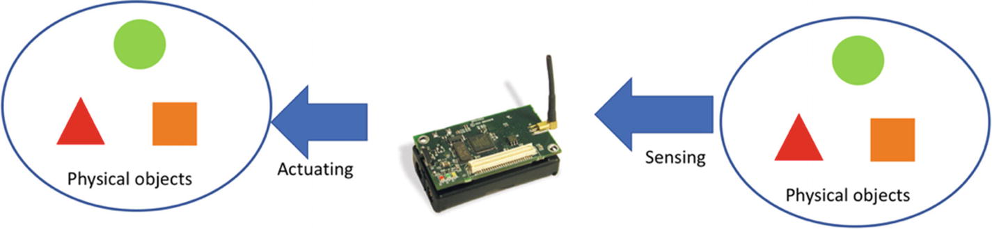
Sensing and actuating are two common terms that are used in embedded topics. In the WSN context, sensing is a process that converts a physical object to digital data. For instance, sensing temperature. The sensor device senses the environment’s temperature and then converts it to digital form. Actuating is a process in which the MCU sends digital data to an actuator device to perform some tast, such as turning on LED lights, sounds, or a motor.
Figure 5-1
Sensing and actuating in a WSN mote
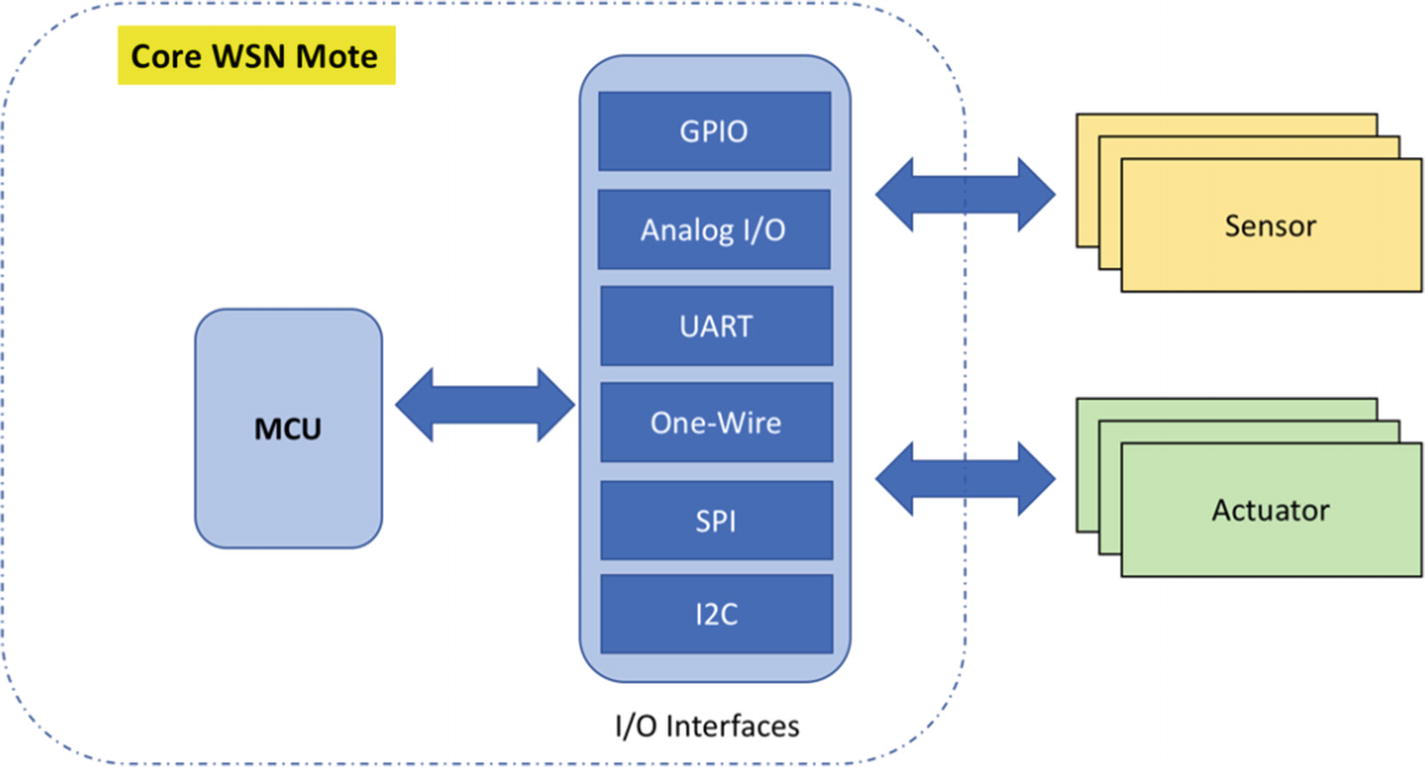
Sensing and actuating are shown in Figure 5-1. Sensor devices that are attached to a WSN mote will sense and then convert the information to digital data form. A WSN mote also can send digital data to the outside environment through actuator devices. Both sensor and actuator devices can communicate to the MCU via I/O interfaces. These interfaces provide various protocols depending on how they are implemented. You can see a communication model in Figure 5-2.
Figure 5-2
Communication model for sensor/actuator devices and MCU
We will start to explore sensor and actuator devices in the next section. Then, we will develop a Contiki-NG program for accessing those devices.
Review Sensor and Actuator Devices
In this section, we will explore common sensor and actuator devices that are used in embedded development environments, including in real applications. All sensor and actuator devices may be found in your local store. However, you can buy them in online stores such as Element14, Digikey, Mouser, SparkFun, Adafruit, DFRobot, SeeedStudio, and more. You can also find them on cheap online stores from China, like Alibaba, Aliexpress, Banggood, and DealeXtreme.
We will now review some sensor and actuator devices that are easier to find. Sensor device samples are temperature, humidity, soil moisture, and gas sensor. Actuator device samples can be LED, active buzzer, and motor. We will check them in the next section.
Temperature and Humidity
Temperature and humidity sensors are used to measure current environment temperature and humidity levels. Some manufactures make these sensors into one chip, but others are still available in separation sensors for temperature and humidity.
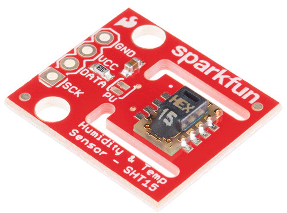
Most WSN motes are designed to include these temperature and humidity sensors. This is useful for our development and testing. We can verify that our program performs sensing and actuating. One example is the SHT1x (SHT10, SHT11, SHT15) chip from Sensirion. You can read its datasheet at https://www.sparkfun.com/datasheets/Sensors/SHT1x_datasheet.pdf. SparkFun provides the SHT15 sensor in a module that is ready to use. It’s the SparkFun Humidity and Temperature Sensor Breakout—SHT15. This product can be bought on the SparkFun website at https://www.sparkfun.com/products/13683. You can see the module in Figure 5-3.
Figure 5-3
SparkFun Humidity and Temperature Sensor Breakout—SHT15
In general, SHT1x provides two-wire pins to be used to access sensor data. If you see a SparkFun Humidity and Temperature Sensor Breakout (Figure 5-3), this module has four pins: VCC, GND, DATA, and SCK. We can develop a program to access this sensor data from MCU.
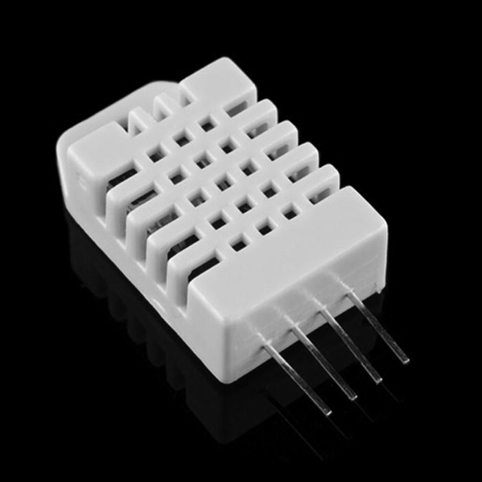
We also can use a low-cost humidity and temperature sensor. It’s the DHT22 module. This sensor is easier to find. You can check it out on the SparkFun website at https://www.sparkfun.com/products/10167; it is called Humidity and Temperature Sensor—RHT03 (DHT22). The DHT22 sensor provides a single-wire digital interface that is used to access sensor data for temperature and humidity. The DHT22 sensor form is shown in Figure 5-4.
Figure 5-4
Humidity and Temperature Sensor—RHT03 (DHT22)
Soil Moisture
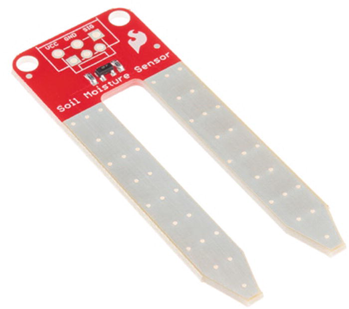
A soil moisture sensor can be used to measure the moisture level in soil. This sensor can be applied in monitoring systems for gardens. There are many soil-moisture models that you can use in your design. One with a low cost is a Soil Moisture Sensor from SparkFun, found at https://www.sparkfun.com/products/13322. The SparkFun Soil Moisture Sensor can be attached via an analog pin (ADC pin) to obtain the moisture level. You can see a SparkFun Soil Moisture Sensor in Figure 5-5.
Figure 5-5
SparkFun Soil Moisture Sensor
Gas Sensor
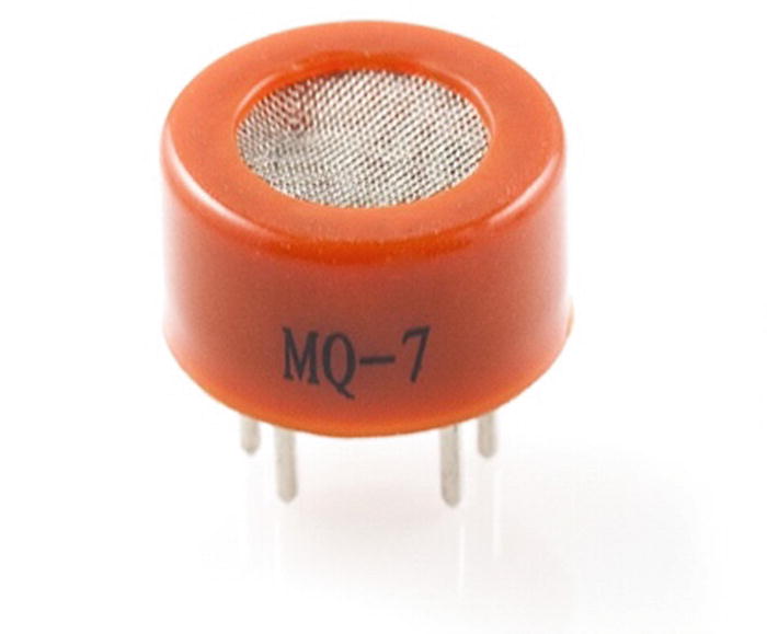
In some scenarios, you may need to monitor for gas such as carbon monoxide (CO). You can attach a carbon monoxide sensor to a WSN mote through an analog pin so as to detect it. One such sensor is Carbon Monoxide Sensor (MQ-7). This sensor can detect gas concentrations anywhere from 20 to 2000 ppm. You can find it on the SparkFun website at https://www.sparkfun.com/products/9403. Figure 5-6 shows the Carbon Monoxide Sensor (MQ-7). Further information about this gas sensor (MQ-7) can be found at https://cdn.sparkfun.com/datasheets/Sensors/Biometric/MQ-7%20Ver1.3%20-%20Manual.pdf.
Figure 5-6
Carbon Monoxide Sensor (MQ-7)
LED
An LED is a simple actuator device. It can be used for lighting indicator and notification, processing status, or indicating a certain state. There are various models and colors for LEDs. You can choose it to fit with your case. Figure 5-7 shows a sample LED.
Sometimes you need an actuator that generates a continuous sound to inform the user of a particular state, such as low power on battery, problem on a certain system module, or waiting for an action. An active buzzer can be used as an actuator device to indicate a certain notification. This actuator is low cost and easier to find.
In general, an active buzzer has two pins, GND and SIG. It’s easy to use because we just send a digital value (3.3V or 5V) on the SIG pin to generate a continuous sound. The sound will be stopped if we set 0V (GND) on the SIG pin. You can see this actuator in Figure 5-8.
Figure 5-8
Active buzzer
Motor
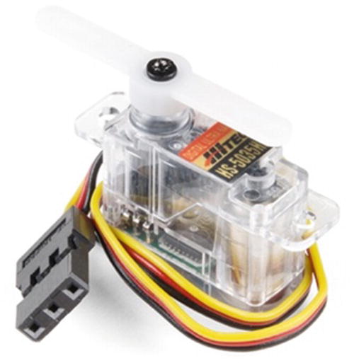
To control mechanical stuff, you may need a motor that is designed for the MCU to make a movement or rotation. There are various motor models. A servo motor is a basic motor that can be integrated with a WSN mote. You should keep in mind that some motor models need a lot of power, and they should not get that power from your WSN mote. You can use an external power adapter for your motor. The manufacturer also provides a motor driver that addresses motor power issues.
One servo motor is the Hitec HS-5035HD servo with Ultra Nano Size. You can buy it on the SparkFun website at https://www.sparkfun.com/products/14210. Figure 5-9 shows a Hitec HS-5035HD servo.
Figure 5-9
Hitec HS-5035HD servo with Ultra Nano Size
Sensing in Contiki-NG
Each sensor in Contiki-NG should implement sensors.h from the <contiki-ng-root>/os/lib folder. We can access the sensor device library using the following code:
SENSORS_ACTIVATE(sensor_xyz);
...
val = sensor_xyz.value(SENSOR_XYZ_TYPE);
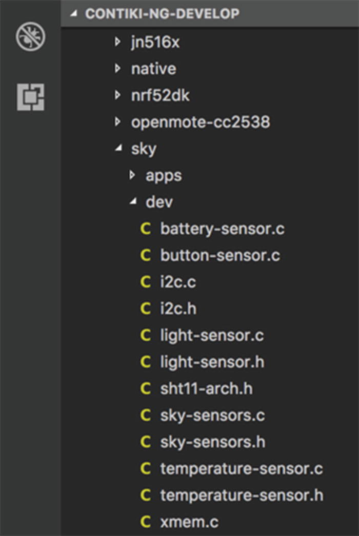
sensor_xyz is a defined variable for the sensor device. This is a part of each Contiki-NG device platform. Each sensor device has sensor types that will be called on the value() method. Your sensor code (*.c and *.h) should be put in the dev/ folder from the Contiki-NG platfom. You can see a list of sensor codes in Figure 5-10.
Figure 5-10
Sensor and actuator libraries for Sky platform
In the next section, we will build a simple demo for sensing using the existing sensor in Contiki-NG. I use a TelosB for testing.
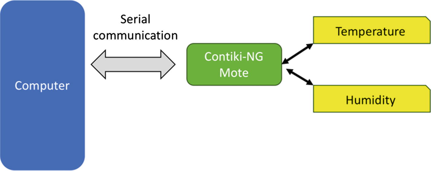
For this demo, we will build the scenario that is shown in Figure 5-11. A Contiki-NG mote with sensor device is attached to a computer. We will sense temperature and humidity via the SHT11 sensor. After acquiring the temperature, the mote will send this sensor data to a serial port on the computer. We will print this sensor data in Terminal by reading the serial port.
Figure 5-11
Sensing demo scenario
Creating a Project
To create a new project on Contiki-NG, you can create a folder, for instance, sensing. Then, add sensing.c and Makefile files. Our program that uses the sensor device will be implemented in the sensing.c file. We define our project configuration in the Makefile file.
The following is the content of the Makefile file:
CONTIKI_PROJECT = sensing
all: $(CONTIKI_PROJECT)
CONTIKI = /home/agusk/contiki-ng/
include $(CONTIKI)/Makefile.include
Change CONTIKI to your Contiki-NG path.
Next, we will write a Contiki-NG program on the sensing.c file.
Writing a Program
We will build a Contiki-NG program to acquire the temperature every five seconds. We use etimer to implement our timer object.
The following is the complete program in the sensing.c file:
Firstly, we activate the timer and our SHT11 sensor on the TelosB:
etimer_set(&et, CLOCK_SECOND * 5);
SENSORS_ACTIVATE(sht11_sensor);
PROCESS_WAIT_EVENT_UNTIL(etimer_expired(&et));
After etimer has raised the time, we sense temperature by calling value() from the sht11_sensor object and passing the SHT11_SENSOR_TEMP parameter. Since we face displaying float data, we calculate decimal and fraction separately:
val = sht11_sensor.value(SHT11_SENSOR_TEMP);
if(val != -1)
{
s= ((0.01*val) - 39.60);
dec = s;
frac = s - dec;
// print float data
printf("Temperature=%d.%02u C . VAL=%d
", dec, (unsigned int)(frac * 100),val);
}
We also do a similar task to sense humidity. We pass SHT11_SENSOR_HUMIDITY to read humidity from sensor:
Now, you can test the program. You should compile and deploy this program into Contiki-NG:
$ make TARGET=sky
$ make TARGET=sky savetarget
$ make sensing.upload TARGET=sky
After uploading a program into Contiki-NG, we try to monitor the serial output from the Contiki-NG mote. You can type this command to do so:
$ make login TARGET=sky
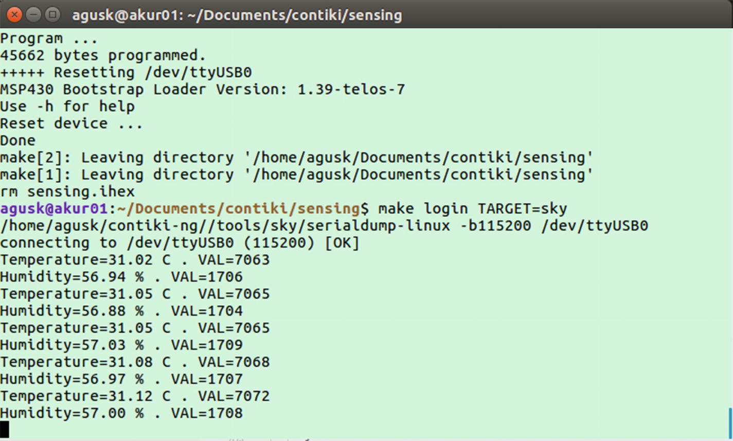
If it succeeds, you should see the current temperate and humidity values in Terminal. You can see my program output in Figure 5-12.
Figure 5-12
Program output on sensing application
Actuating in Contiki-NG
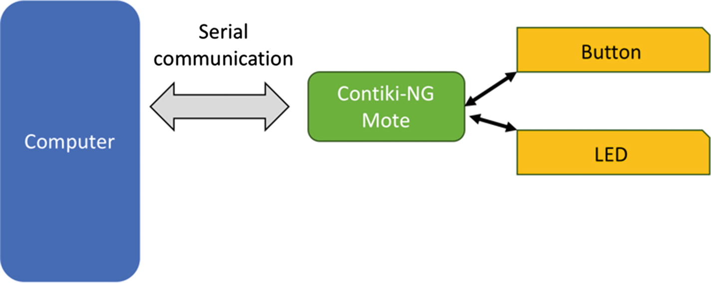
In this section, we will learn how to work with actuating in Contiki-NG. There are a lot of actuator devices that you can use with Contiki-NG. For this demo, I will use a button and an LED as actuator devices. In general, these actuator devices are available on some Contiki-NG motes.
This demo is shown in Figure 5-13. If the user presses the button, the LED will be toggled. I use TelosB for this demo as it already has a button and an LED.
Figure 5-13
Actuating demo scenario
Creating a Project
You can start a new project by creating a folder, called actuating. Then, add Makefile and actuating.c files. In the Makefile file, we configure our project. You can write the following Makefile content:
CONTIKI_PROJECT = actuating
all: $(CONTIKI_PROJECT)
CONTIKI = /home/agusk/contiki-ng/
include $(CONTIKI)/Makefile.include
Change CONTIKI to your Contiki-NG path.
Next, we will build a program in the actuating.cfile.
Writing a Program
The program will listen for the pressed button from the user. If the user presses the button, we toggle the LED. The following is the content of the actuating.c file:
First, we active the button by calling SENSOR_ACTIVATE(). We then turn all LEDs off for initialization.
SENSORS_ACTIVATE(button_sensor);
leds_off(LEDS_ALL);
Then, we wait for the button to be pressed by the user. We can use PROCESS_WAIT_EVENT_UNTIL() to detect the pressed button. We will toggle the LED after the button is pressed:
while(1)
{
PROCESS_WAIT_EVENT_UNTIL(ev == sensors_event &&
data == &button_sensor);
leds_toggle(LEDS_BLUE);
}
Testing
Now, you can test the program. You should compile and deploy this program into Contiki-NG:
$ make TARGET=sky
$ make TARGET=sky savetarget
$ make actuating.upload TARGET=sky
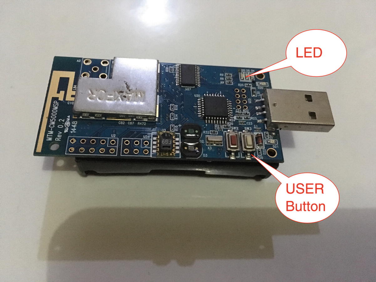
You can press a user button on the Contiki-NG mote. You will see an LED light up while you press the button. You can see the user button and the LED on a TelosB in Figure 5-14.
Figure 5-14
User button and LED on TelosB
Customizing Sensor and Actuator Devices
You probably want to expand your sensors and actuators on your Contiki-NG mote. In the real world, some Contiki-NG motes do not provide built-in sensors and actuators. Others only have one or two sensor devices.
In this section, we will explore how to add additional sensor and actuator devices to Contiki-NG motes.
Expansion Connector
Some Contiki-NG motes are designed to enable you to expand their board. One option is to provide an expansion connector. The board design exposes MCU pins in order to make additional external sensors, actuators, or other devices interact with the system.
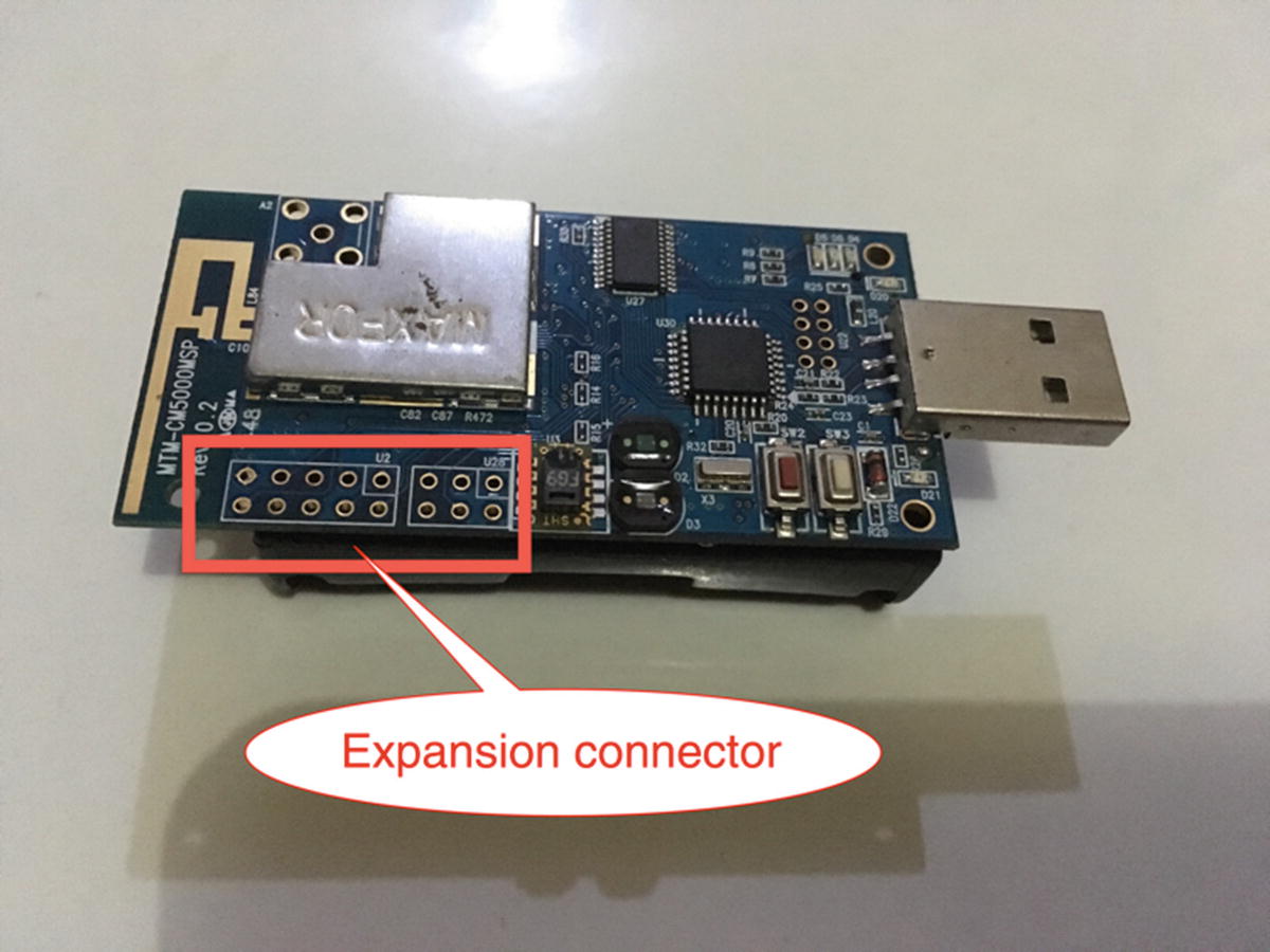
For instance, TelosB has an expansion connector available to enable makers to attach sensors and actuators to the board. You can see it in Figure 5-15.
As seen in Figure 5-16, we can attach sensor and actuator devices to the mote. GPIO pins such as ADC and I2C are accessible from the main board. You can do wiring for your sensor and actuator devices.
Figure 5-16
Expansion connector pinout from TelosB
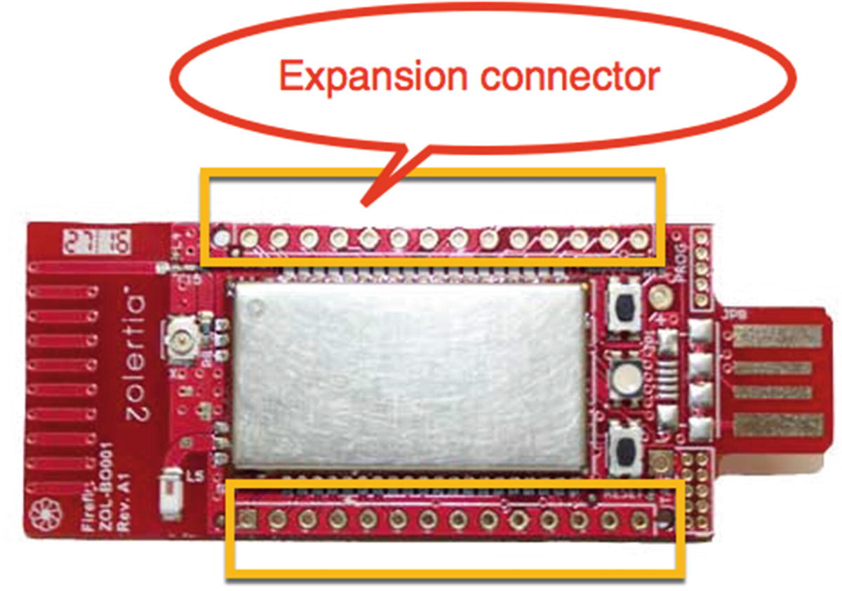
Another board, such as Zoul from Zolertia, https://zolertia.io/zoul-module/, can be attached to your own board. Zolertia also provides a complete development kit, Firefly. You can develop Contiki-NG on top of the board. Further information about Firefly can be found at https://zolertia.io/product/firefly/. Figure 5-17 shows a form of the Firefly board.
Figure 5-17
Expansion connector on Firefly
Sensor and Actuator Drivers for Contiki-NG
Each sensor or actuator device attached to Contiki-NG should provide an API driver. In this section, we will explore how to make device drivers for Contiki-NG.
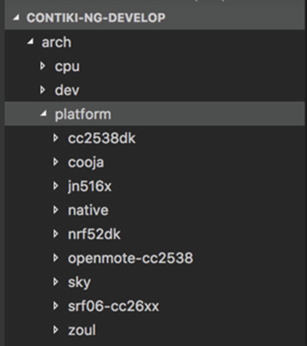
Each Contiki-NG mote platform has a different development style. You should decide what Contiki-NG platform you will use for additional sensor and actuator devices. If you have a plan to develop sensors and actuators for all platforms, you can put your drivers at <contiki-ng-root>/arch/dev. Otherwise, you can put them at <contiki-ng-root>/arch/platforms/<your-platform>. You can see it in Figure 5-18.
Figure 5-18
Platform API on Contiki-NG
For demo purposes, we will develop a driver for the Sky platform. We build a sensor that is attached into TelosB via an ADC0 pin. Next, we will write a driver program for the Sky platform.
We add two files, mycustom-sensor.h and mycustom-sensor.c. These files are put in the <contiki-ng-root>/arch/platform/sky/dev folder. You can see them in Figure 5-19. We extend our custom sensor driver from the sensors.h and sky-sensors.h files.
The following is the content of the mycustom-sensor.h file:
Now we implement the mycustom-sensor.c file. The ADC0 pin is attached on ADC12MEM0. Since we implement sky-sensors.h, we should implement the value(), configure(), and status()methods.
The following is the content of the mycustom-sensor.c file:
Last, we should add our driver file into the Makefile.sky file from the Sky platform. It is located at <contiki-ng-root>/arch/platform/sky/Makefile.sky. In our case, we move the mycustom-sensor.c file into the Makefile.sky file. You can see the bold code for adding the driver file here:
include $(CONTIKI)/arch/platform/sky/Makefile.common
MODULES += os/net/mac os/net/mac/framer os/net
arch/dev/cc2420 arch/dev/sht11 arch/dev/ds2411
os/storage/cfs
Your custom sensor driver is ready for Sky platform. You can use it as usual. For instance, you create a project by creating a folder, custom-sensing. Then, you add Makefile and custom-sensing.c files.
We will access our driver, mycustom-sensor, in our project. We use the same program from the sensing project but change it to use our own sensor. The following is the complete program for the custom-sensing.c file:
Last, we should configure our project in the Makefile file:
CONTIKI_PROJECT = custom-sensing
all: $(CONTIKI_PROJECT)
CONTIKI = /home/agusk/contiki-ng/
include $(CONTIKI)/Makefile.include
Change the CONTIKI value to your Contiki-NG path. Now, you can compile and upload this program to TelosB:
$ make TARGET=sky
$ make TARGET=sky savetarget
$ make custom-sensing.upload TARGET=sky
After uploading a program into Contiki-NG, we try to monitor the serial output to see our custom sensor on Terminal:
$ make login TARGET=sky
You should see your reading values from ADC on Terminal.
Summary
We have reviewed some sensor and actuator devices. We also have learned how to work with sensing and actuating in Contiki-NG. Last, we developed a custom sensor to attach to a Contiki-NG mote through its expansion connector.
In the next chapter, we will learn how to build networking and communication in Contiki-NG. That is at the core of Contiki-NG’s features.