
![]()
Unlike a standard computer, the Raspberry Pi is unlikely to alter the temperature of your room (well, unless you have a cluster of them: then you may have heat issues). It’s widely known that high temperatures can affect your computer. Nowadays most new machines have protection circuits to ensure that they do not let the magic smoke out, although this has not always been the way with electronics in computers. Not so long ago, if you seated your heatsink incorrectly you were more than guaranteed to let the magic smoke out, usually with a loud bang or a lot of smoke (see Figure 3-1 for the results).
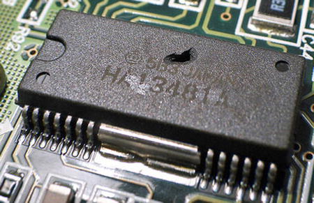
Figure 3-1. Someone let the magic smoke out!
I am sure most people will know someone or have heard of someone who had seated a heatsink incorrectly on socket A of the AMD Athlon. That never ended well, given the heatsink had no thermal shutoff; more often than not it simply exploded. In addition to this, the CPUs of the late 90s often did not have the advanced temperature monitoring that you see today. A lot of the time the temperature was measured with a simple thermistor placed in the bottom of the socket, which made it a little hard to know when the CPUs were getting a little too hot because you were never measuring the actual core temperature. That’s why it was important to have an external sensor if you wanted a good idea of the temperature. Nowadays this is less of an issue, so this chapter will look at monitoring the temperature of your room or some other space like inside a rack, for example (or your cluster of Raspberry Pis). The Raspberry Pi as it comes has no way for you to monitor an external temperature source. There is no sensor on board like you often see on common motherboards. The only temperature you can measure is the internal graphics processing unit (GPU) that is part of the SoC. That won’t be very helpful to you for reading an external temperature.
This is not too much of a worry for you because the Raspberry Pi comes with very useful GPIO headers. There are quite a few different ways you could read an external temperature from the Raspberry Pi’s GPIO pins. You could use a simple thermistor if you wanted or you could use something more advanced, based on the 1-wire protocol. The GPIO pins you have access to could support any of these methods.
This all sounds a bit complicated. Why can’t you just use a digital temperature sensor? Aside from that being extremely boring it’s also not very versatile. With the Raspberry Pi you can do much more. You now have the option of using many different types of sensors and different connection methods. You now also have the ability to log the data for future reference. Or you may want to perform an action once the sensor hits a certain reading. Or maybe you just want to broadcast to the word what temperature your home rack is at. Given the Raspberry Pi’s small size and low power requirements you could be coupled with WiFi to set up a remote temperature station outside. The possibilities are endless.
This project is designed to be simple and cheap; at the same time I hope that it opens your eyes to how easy a hardware project can be with the Raspberry Pi. It’s not scary and it’s not overly hard to understand. I will start off by talking about the GPIO pins a little more. After that I will discuss the sensors I will be using and how they will be connected. This will include an introduction to the 1-wire protocol and why it’s good for this type of project. After that I will show you a basic circuit that requires no soldering in order to take your first temperature reading.
Since this is the first time you have used the GPIO pins, I would like to spend a little bit of time discussing the physical side of them. After reading Chapter 1 you will have a good idea what makes up the GPIO pin headers and also what functions you can get from them. I won’t go back over all those details in this chapter. There are a few simple guidelines you should follow when working with the Raspberry Pi’s GPIO pins.
The first point and the most important one to remember is that the GPIO pins are not tolerant of 5 V. If you try and source 5 V from your GPIO headers and you’re lucky, your project just may not work. If you’re unlucky, you will let the magic smoke out of something and if you’re really unlucky that something will be the Raspberry Pi. If your project has more than 5 V and your Raspberry Pi’s GPIO pins get connected to this you will let the magic smoke out of your Raspberry Pi.
There are various methods for protecting your GPIO pins. You can use something fancy like an optocoupler to fully isolate your Raspberry Pi. This may be needed for some projects, like if you were going to interface with high-voltage circuits. You could also do something super basic and use a Zener diode. If you place a 3.3 V Zener diode between the ground and the GPIO pin you intend to use, you will have a small amount of protection. If you attempted to apply more than 3.3 V, the diode would burn out. Once this occurs the circuit is broken and the dangerous voltage would never be received by the GPIO pins.
Personally, unless I am designing a project that absolutely needs protection, then I don’t worry. I’d rather take the approach of checking everything I do more than once, making sure I won’t supply 5 V to the GPIO pins. This is a good habit to get into, as you will find mistakes and fix them before they become an issue. I don’t like to be sloppy as I know the protection will save me: I’d much rather check it and get it right. I also tend to use breadboards for all my prototyping work. This makes things so much easier to work on. Do yourself a favor and get a few of them of various sizes: you won’t regret it! In Figure 3-2 you can see some of my breadboards.

Figure 3-2. A collection of breadboards
Also by using breadboards you can simply use a jumper wire from your Raspberry Pi and connect it to the breadboard. By doing this you won’t accidentally connect the wrong GPIO pin; it makes it much clearer when you’re building the projects. If you take a close look at Figure 3-3 you can see that the holes are in certain patterns.

Figure 3-3. A closeup of a generic breadboard
On most breadboards you will find the two edge tracks that are connected down the length of the breadboard. These are normally used as your voltage source and your ground tracks. You can then see that the breadboard is divided into two equal halves. No current can flow across the divider strip in the middle of the board. The holes in these sections are connected across the width of the board, but only in their set section. Other breadboards may have different configurations. If you are ever unsure of how the holes are connected you can use the following simple method to check.
- Place a jumper wire in one of the holes and then place another jumper wire into the next hole.
- Run a continuity check on your multimeter.
- Keep moving the second jumper wire around the adjacent holes to work out how the breadboard is connected.
Once you know how the tracks on your breadboard flow, you can work out how best to place your components. There are no hard rules about the placement of components. Just do your best to keep it neat and logical. This will make it easier to debug if you need to. To insert wire or components into the breadboard, gently press their legs into the hole: they won’t go in too far and you will have things that stick out. Removing them is just as easy. Pull directly upward and not at an angle to remove the components. If you pull them out at an angle you may bend the legs. If they seem hard to remove, use a little flat-bladed screwdriver to lever each side up gently. I find that some integrated circuits (ICs)s tend to be hard to remove and you often need to gently lever them up.
I will be using two different sensors. Each sensor will be connected in different ways to the Raspberry Pi, so that I can show you how flexible the Raspberry Pi really is. Let’s start with the sensors.
Although I do have a strong preference for which sensor is better when connected to the Raspberry Pi, I’ll start off by talking about each sensor and why I like a certain type. First up I will talk about the DHT11. The DHT11 is an eight-bit restive-type temperature and humidity sensor in one small package. The eight-bit value refers to the temperature restitution. These will come in many different colors and appearances: it’s a very generic part made in China. They are easy to find and very cheap.
Sensitivity-wise, they are not too bad. The temperature range is 0 to 50°C and humidity is 20% relative humidity to 90% relative humidity. Given that Hong Kong is often above 90% relative humidity it’s not the best choice for me. The good thing about the DHT11 is that it is in such a small package you can sense both temperature and humidity. It also has a low pin count. You will most often see the DHT11 shipped with four pins although you only need three. You can see the pins in Table 3-1.
Table 3-1. The pins for the DHT11
| Pin Number | Function |
|---|---|
| 1 | Voltage Drain To Drain or Vdd (3–5 V dc) |
| 2 | Data (proprietary digital signal) |
| 3 | No connect |
| 4 | Ground |
You may have noticed I mentioned the fact that the data signal is proprietary. When I say proprietary I don’t mean it in the sense that all documentation is locked away under a nondisclosure agreement, although some is. What I mean in this case is that it’s not using a well-known bus or protocol, say, like, 1-wire or the I2C bus. While this makes it slightly harder to use, it’s not impossible. The DHT11 is very sensitive with timing. When you first start communicating with the sensor the following must occur.
- First, the controlling device must pull the data bus low. When the controlling device pulls this bus low it must take at least 18 ms. Otherwise, the DHT11 will not detect that the controlling device wants to do something.
- After this 18 ms the controller then pulls the data bus high. The controller must do this for between 20 and 40 μs. During this time the DHT11 will send out a response.
- As soon as this occurs the DHT11 will then pull the data bus low for 80 μs. If the controller attempts to pull this bus high at this time the start process would be aborted.
- After the 80 μs is up without interference, the DHT11 will then pull up the data bus.
- The DHT11 will keep the data bus high for another 80 μs. At the end of this time frame the DHT11 will finally start to transmit actual data.
Take a look at Figure 3-4 and you can see an example of the start signal.

Figure 3-4. The start signal for the DHT11
You can see that the DHT11 is quite timing-sensitive. This is where the first issue under Linux comes in. Linux will do its best to abstract the hardware from you, by providing device nodes from the kernel. In normal situations this is a very good thing. For example it makes it simple to access your serial port and use it as a TTY terminal. Where it’s not very good is for low-level hardware operations, for example, a timing-sensitive temperature sensor. The only real way to ensure that the DHT11 works correctly under Linux would be to write some C code to handle the low-level timing that is required. This type of sensor is best used on a micro-controller like the Arduino. Because I have an Arduino, this was the first sensor I picked out for this chapter, only to come to the conclusion it’s not the best fit for the Raspberry Pi. So if the DHT11 is not a good fit, what is and why?
The DS18B20, of course! The what? The DS18B20 is a 9 to 12-bit temperature sensor; unlike the DHT11 it’s just a pure temperature sensor and is not capable of sensing humidity, although the sensitivity of the DS18B20 is much better than the DHT11 with a range from -55°C to +125°C. With the sensor being so small you could place it anywhere; it’s about the size of your common TO-92 transistor. There is one feature that the DS18B20 has that the DHT11 is missing and that is a temperature alarm. The DS18B20 can alert you over its bus when it hits a user-set temperature. You can set one high-temperature alarm and one low-temperature alarm. For its voltage and current draw, it’s perfect for the Raspberry Pi, only needing +3 V and under 1.8 mA. You could power and drive this sensor with one wire from the Raspberry Pi, but more on that later. It has the same number of legs as a transistor as well. Take a look at Table 3-2 to see what each leg (pin) of the DS18B20 is used for.
Table 3-2. The pins of the DS18B20
| Pin Number | Function |
|---|---|
| 1 | Ground |
| 2 | DQ (data input/output) |
| 3 | Vdd (optional) |
You will notice I’ve left the Vdd as optional in Table 3-2. How can Vdd be optional? The DS18B20 can support parasite power. This means that with only one wire you can power and transmit data to and from the device. This is part of the 1-wire protocol. I have not listed a protocol or talked about the protocol that the DS18B20 uses. Unlike the DHT11, the DS18B20 uses an industrial standard called the 1-wire bus.
What exactly is a 1-wire bus? Excluding the ground connection of the 1-wire device, both data and power can be transmitted across one wire, hence the name “1-wire.” The 1-wire bus was developed by Dallas Semiconductor, now called Maxim Integrated. The 1-wire bus has been around for a very long time. It’s been used in public mass transport systems all the way down to simple security tokens. Its main benefit over other similar low-speed buses is that the 1-wire device can be on the end of a very long cable run without too much signal degradation. Like other bus systems the 1-wire bus supports more than one device on the bus, which is referred to as multidrop in 1-wire deployments. Each 1-wire device has a unique 64-bit serial code embedded into the device. This is how the controller device can identify each device on the 1-wire network. The embedded serial code can be broken up into three distinct segments.
- The first segment is called family code; this segment identifies what type of device it is and it’s eight bits wide. There is a set device list that all 1-wire devices must comply with.
- The middle segment is called the ID segment and it’s 48 bits wide. This 48 bits of data must be unique within the given family of devices. This is what gives you the ability to have many 1-wire devices on the same wire.
- The remaining eight bits of serial code are a cyclic redundancy check, or CRC, checksum and must match the rest of the address.
See Table 3-3 for an example of a serial address.
Table 3-3. Example of a 1-wire address
| Family Code | ID | CRC |
|---|---|---|
| 8 bit | 48 bits (unique to family) | 8 bits |
| 10 | 0008027e34 | ca |
In Table 3-3 the full 1-wire serial code would be “100008027e34ca.” This is very simple to break down.
- The first part of the address, “10,” maps to the “high precision digital thermometer” class; you will need access to the list of devices and their family for this. You can find the device and family table at http://owfs.sourceforge.net/commands.html.
- The next 48 bits (“0008027e34”) compose the unique address.
- Finally, the “ca” is the CRC checksum of the address.
The 1-wire network is called a micro LAN. On the micro LAN there can only be one master controller and many slave devices. A key feature about the 1-wire bus is that it’s implemented at a software level. You don’t need special hardware or a special bus to be able to run the 1-wire devices. In fact the 1-wire bus at a hardware level is very boring and very simple. This makes it perfect for your first project. Take a look at Figure 3-5. You can see an example of a 1-wire bus using parasite power for two temperature sensors.

Figure 3-5. An example of a 1-wire bus
Parasite power is a magic part of each 1-wire device. Without this you would need a minimum of three wires for each device. A 3-wire bus sounds nowhere near as impressive as a 1-wire bus, now does it?
How can you have Vdd and data signals on the same bus? It’s simple really; it’s all a matter of timing, but you can’t have them at the same time. Whenever the 1-wire device is not communicating with the controller, the data bus is pulled high. When this state occurs, an internal capacitor inside the 1-wire device will receive a charge from the data bus. This internal capacitor will take care of itself and you won’t even know it’s there. Now when the 1-wire device wishes to communicate with the controller it will pull the data bus low. At this point in time the 1-wire device will use the stored charge from the capacitor to power the circuit inside the 1-wire device. In our case it will power the DS1820B’s temperature probe and logic.
You will notice that there is a resistor between Vdd and the data line. What’s that for? That’s the pull-up resistor. Its job is to grab the data bus line and pull it high at all times. This allows the 1-wire client device to pull the bus down when needed or to release the bus when not needed, thus letting the data bus be pulled up. In this chapter I will use a 1.0K ohm resistor. How did I come to this value? Well, I didn’t: I read the data sheet of the DS18B20. From the data sheet I can work out this value. The value was picked to work well in parasitic mode and standard mode. If you wanted just standard mode I would recommend a 4.7K ohm or a 10K ohm resistor. Data sheets are your new friends as of this chapter. Find them, read them, and keep them handy! You will notice that a lot of 1-wire projects use the same value of the pull-up resistor as well. It’s a fairly common value in 1-wire projects and will allow you to use a Vdd of 5.0 V or lower without a worry. For the Raspberry Pi you should be sticking with 3.3 V if you intend to keep the magic smoke in.
The 1-wire has one main thing you must keep in mind. You need to have direct hardware access. On a lot of other platforms like common computers, the 1-wire bus is controlled via the serial port. It’s not a serial protocol in that sense. The 1-wire functionality makes use of the serial port and runs its own communication protocol over the underlying hardware. The 1-wire protocol pretty much hijacks the underlying hardware on your system. Lucky for you, the Raspberry Pi comes with the GPIO headers. Linux has a kernel module for the 1-wire protocol over GPIO. You just need to set it up and scan the micro LAN for devices.
By now I would have assumed that you can see the DS1820B has been the better solution for you under Linux. It’s cheap, it’s easy to run, and it’s well supported within the Linux kernel. In this chapter I will mostly focus on setting up the 1-wire bus and the DS1820B. I will show you how you can use the DHT11 as well, just in case you have one lying around with no use. Let’s get started with your first hardware project. I promise it will be simpler than you expect.
Here are the parts you are going to need:
- One DS1820B temperature sensor
- One 1K ohm resistor
- One 10K ohm resistor (only for the DHT11 section)
- One DHT11 sensor (only for the DHT11 section)
- Jumper and hook-up wire
- Breadboard
Let me show the sensors you will be dealing with first. In Figure 3-6, you can see the small little black DS1820B and the blue square DHT11.
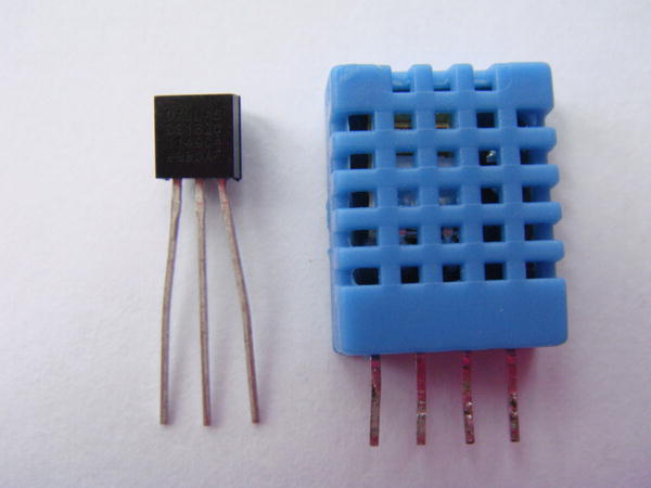
Figure 3-6. The DS1820B and DHT11 side by side. Fight!
Using the Little Black DS1820B
Here is how to use the DS1820B. In Figure 3-7 you can see the circuit schematic diagram. In this drawing I have included two drawings in the same figure. One is the standard wiring method and the other is the parasitic method. This will also show you how little the circuit will change between the two methods.
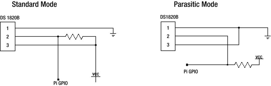
Figure 3-7. Circuit schematics for the DS1820B
As you know there are two ways in which you can connect the DS1820B to the Raspberry Pi. The first way has no special name and is thus called the standard mode; you’re just connecting all the pins of the sensor to their respective type. This method is a good way to start, as sometimes using the sensor in parasitic mode can cause issues.
- First, you need to know where pin 1 is on your DS1820B. Pick the sensor up and you’ll notice it has two distinct sides. One side is curved and one side is flat with some text on it. The flat side with the text is the front of the device. When facing the flat side of the sensor, the pin on the left-hand side is the first. You should check your data sheet as well, remember them? Your new friends! Go take a look and check the pin out. If you do manage to insert the DS1820B in the wrong direction, don’t worry it will get really hot but won’t blow up. Take it out and let it cool down for some time; keep it still until it’s cool enough to pick up.
- Now that you have pin 1, insert the sensor into your breadboard. To make it easy for yourself, insert pin 1 into row 1 on the breadboard. You can see how I have inserted my sensor in row 1 at the top of the breadboard in Figure 3-8.
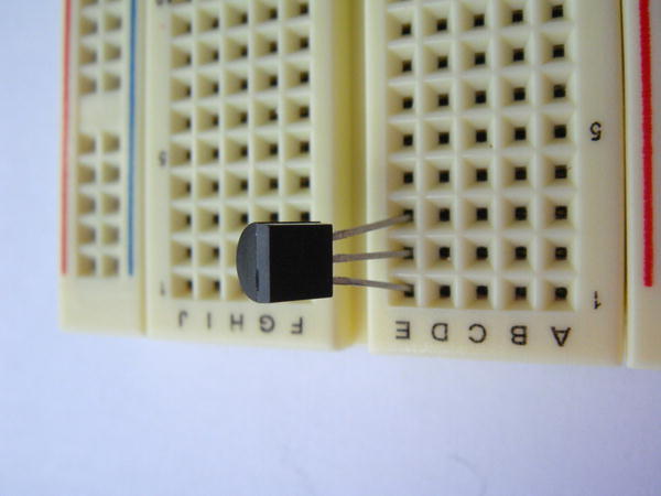
Figure 3-8. The DS1820B inserted
- Breadboards make this type of prototyping work simple; they should be your second best friend (just don’t let the data sheets know)! Next up, insert the jumper wire. In standard mode you need to feed the sensor power and provide a ground. So connect pin 1 to ground on the breadboard and connect pin 3 to your 3.3 V source. You can see how I have inserted my jumpers in Figure 3-9.

Figure 3-9. Jumpers installed into the breadboard
- Now you need to install a resistor. This resistor is the pull-up resistor. You must insert it between pin 2 and pin 3. Place this close to the edge of the board. Have a look at Figure 3-10 for an example of a good placement. Why is that a good place? This is the pull-up resistor and it needs to follow the connection from the Raspberry Pi’s GPIO pin. If you were to place the resistor before the connection your sensor won’t work.

Figure 3-10. Good resistor placement
- After this, you insert a hook-up wire from between the sensor and the resistor to P1-07 (GPIO-4) on the Raspberry Pi. In Figure 3-11 you can see the final connection. In Figure 3-11 you can see you have used all three pins (this is standard mode, remember). In a multidrop long-range deployment that would be a lot of wires! This is where the parasite mode comes in.

Figure 3-11. The final connections in standard mode
- Now go ahead and pull everything but the DS1820B off your breadboard. Once again, start off by connecting your jumper wires. Connect pin 1 to ground as shown in Figure 3-11. Now place a jumper between pin 1 and pin 3. According to the data sheets for the DS1820B you must tie the Vdd line to the GND line. You’re going to need to place a jumper wire out from pin 2 to a new row on the breadboard. Take a look at Figure 3-12: it will be much easier to see how I have done it.
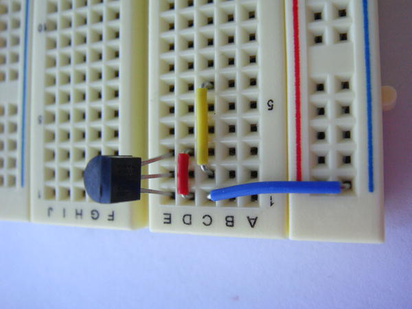
Figure 3-12. Jumpers for the parasite mode installed
- Remember the pull-up resistor? I hope you do! It is an important part of the 1-wire bus. You need to place this resistor in between the new row on your breadboard and your 3.3 V source. You then connect a hook-up wire from the opposite side of the row to P1-07 (GPIO-4) on your Raspberry Pi. Figure 3-13 will help you understand this.
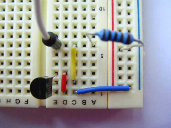
Figure 3-13. Resistor and GPIO connected to the new row
All the connections are made now. Turn on your Raspberry Pi and turn on the power source for your breadboard. You can connect the GPIO pins while the Raspberry Pi is powered on as well. You could also power the sensors from the Raspberry Pi itself if you wanted to. I tend to avoid this as a safety measure.
There is a very good reason why I picked P1-07 (GPIO-4) on the Raspberry Pi. I did not just randomly select it. Recall I spoke about the 1-wire protocol hijacking the serial port? You’re going to do something similar with the GPIO. Lucky for us now, in the stock Raspberry Pi kernel (after August 2012) the w1_gpio module has coded GPIO-4 as the 1-wire bus. If this had not been done you would have needed to set this yourself in the source code for the w1_gpio module and rebuild your kernel. Lucky for us, you don’t need to. First, you’re going to need to load the 1-wire bus support because this module is not loaded by default. Run the following command to load the 1-wire bus:
# modprobe w1_gpio
When you do this, two things should happen if you’ve connected everything correctly. The first thing that will happen is two messages will be printed in dmesg (see Figure 3-14). You can see where the kernel loaded the 1-wire bus and where the 1-wire master controller found a device.
![]()
Figure 3-14. A 1-wire device is found
The second thing that will happen is the creation of a new bus in the /sys/bus/w1/devices filesystem. Let’s take a look at that now.
In Figure 3-15 you will see two devices. One has the 54-bit serial ID of your 1-wire device and the other will be the w1_bus_master, which is the Raspberry Pi. You are going to be more interested in the device attached, in my case the 10-0008027e34ca. If you take a look at that device you will notice there is not much you can do with it. Take a look at Figure 3-16 as an example.

Figure 3-15. The 1-wire device filesystem listing
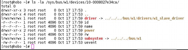
Figure 3-16. Empty 1-wire client filesystem
There is a good reason for this being empty. You have just loaded the kernel module that controls the bus and the bus master. Linux still has no idea what the device is. You’re going to need to load another module. This one is called w1_therm:
# modprobe w1_therm
Nothing will be printed in dmesg this time. If you now take a look at your 1-wire device filesystem you will see a new entry called w1_slave. This is how you will access the temperature information from the DS1820B. Use cat to find the w1_slave file; if all is well it should print some information for you. There will be a short delay on your shell when you do this. Hopefully your output looks something like Figure 3-17.
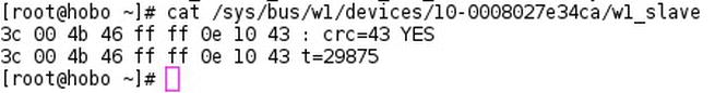
Figure 3-17. Successful output from the DS1820B
Let me show you what the two lines of text mean. Each line can be broken up into segments.
- The first segment of nine hex values is what is directly read from the device. You really don’t need to pay attention to this value on either of the lines.
- The next segment on the first line is CRC=43. This is the checksum value of the data that has been read from the DS1820B. The last section on the first line is YES. This means the checksum matches and your data are valid. If you do encounter a NO value here you can no longer trust any of the information from the sensor and it would be wise to replace the sensor.
- On the second line you have the hex values, as in the first line.
- Then the second part of this is t=, which means temperature equals. Last up you have “29875” in my example. Since this is a high-precision device this measurement actually means 29.875°C. (It’s a little warm sitting under my 30-inch LCD.)
Something simple like this will get you the temperature:
# cat /sys/bus/w1/devices/10-0008027e34ca/w1_slave | grep t= | cut -c 30-31
This should just give you back the first two digits. Later on in this chapter I will show you a simple script to monitor the sensor or log the values to a file.
By default Linux won’t autoload the w1_gpio and w1_therm modules. If you want your 1-wire device to automatically appear on reboot you’re going to need to set up a module autoload file. This will be the same process you used in Chapter 2. Create a file called 1w-therm.modules in the /etc/sysconfig/modules directory. Enter the following into the file:
#!/bin/bash
lsmod | grep -q w1_gpio || /sbin/modprobe w1_gpio >/dev/null 2>&1
lsmod | grep -q w1_therm || /sbin/modprobe w1_therm >/dev/null 2>&1
Save the file and reboot. Now your 1-wire device will be detected on boot on the Raspberry Pi.
Now you have seen what the DS1820B can do and how easy it is to use. I now want to show you how the DHT11 can be used. It’s not as easy to use under Linux as the DS1820B but it can be done. Take a look at the electronic schematics in Figure 3-18. You’ll notice it’s a very simple connection for this sensor.
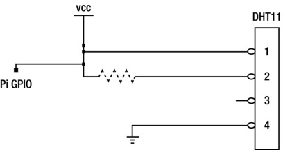
Figure 3-18. Electronic schematics for the DHT11
You can see that you still need a pull-up resistor. It’s not a 1-wire device, but it works in a similar way in that the DHT11 expects the data line to be high at all times; it can then pull it low when required.
One of the nice things about the DHT11 is how simple it is to wire up. It also requires only one data line but you cannot use this device in parasitic mode. Take a close look at the back of your sensor or the data sheet if you can read it. My sensor has a voltage range from 3.6 to 6.6 V. It’s a rather odd range; it also means you must use an external voltage source. I always do, but this time you must.
- Place your DHT11 into your breadboard. I like to place it so that pin 1 is on row 1 of the breadboard. The front of the sensor has all the little square holes. When looking at the front of the sensor, pin 1 is on the left-hand side. Pin 1 is also the Vcc pin. Take a look at Figure 3-19 to see how I have placed the DHT11.

Figure 3-19. DHT11 placement
- Like last time, it’s best to install the jumpers next. Connect one jumper from pin 1 to your voltage source.
- Connect pin 4 to your ground.
- Also connect a jumper from pin 2 to a free row on the side of your breadboard. This allows a clear placement for the pull-up resistor. In Figure 3-20 you can see that my jumper is installed.
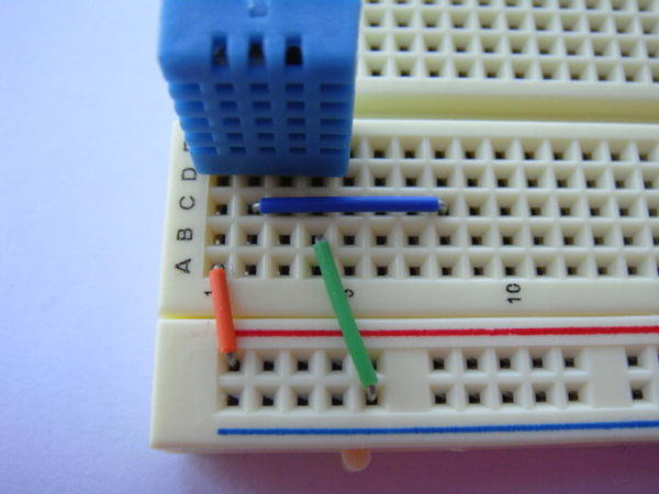
Figure 3-20. Jumpers installed
- Insert your 10K ohm resistor between pin 2 and your voltage source. Place it from your voltage source across to the free row where you installed the jumper from pin 2.
- Lastly, connect a hook-up wire from in front of the jumper wire on pin 2. This will connect to physical pin P1-11 on the Raspberry Pi. See Figure 3-21 for the final working breadboard.
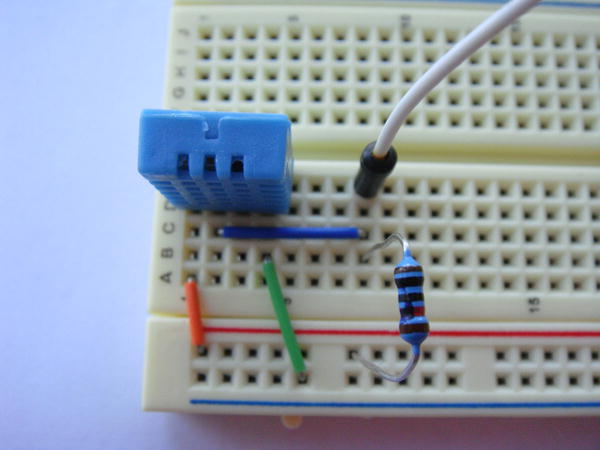
Figure 3-21. All components installed and connected to your Pi
Now you are all ready to let some software access it. Soon you will know just how hot and humid it is! Hong Kong is always very humid so for me this part may not be very useful. With that in mind it’s time to move on to the software part.
With the DHT11 sensor connected, you’re going to need a way to read it. You will recall from the start of this chapter that the DHT11 uses its own digital signaling. To enable you to use this sensor I have included some source code from the excellent Adafruit web site.
![]() Note The application comes as source code. You’re going to need to compile this on your Raspberry Pi. You can download the source code zip file from the Apress web site to get the required files, or you can visit http://rpi.horan.hk to get the source code.
Note The application comes as source code. You’re going to need to compile this on your Raspberry Pi. You can download the source code zip file from the Apress web site to get the required files, or you can visit http://rpi.horan.hk to get the source code.
Now that you have the source code unpacked, you will see three files:
- A make file
- Adafruit_DHT.c
- Adafruit_DHT.o
These three files are the source code, an object file, and a make file. Because all the hard work has been done for you, the main file you care about is the make file. This file tells the make application how to build the Adafruit_DHT.c source into an application. Go ahead and invoke the make application by running the following command in the project directory:
# make
You will quickly notice that it won’t work:
-bash: /usr/bin/make: No such file or directory
Or something similar will appear. By default the Raspberry Pi Fedora image comes with no development tools. Go ahead and install make with this command:
# yum install -y make
Now that you have make installed, shouldn’t it be fine?
Nope. You are now most likely getting this error:
make: gcc: Command not found
gcc is the tool you use to build c and other programs. Install gcc with this command:
# yum install -y gcc
gcc is quite big so this may be a good time to grab a nice beverage or two (in my case a tin of Tsing Tao).
Once gcc is installed you can type in make again. You will notice once again it has failed, this time with some cryptic message about the BCM2835 not being found. You can see the full error in Figure 3-22.

Figure 3-22. Link error for BCM2835 headers
The BCM2835 is what powers the Raspberry Pi. If you also look at the error message you will notice that the build process is trying to link the BMC2835 header files. Exactly where do you get the header files from? They sure don’t ship with Fedora. You can download the BCM2835 headers from http://rpi.horan.hk or the Apress web site. There is one thing to note: this project depends on version 1.8 of the BCM header files; newer headers will not work. Once you have this downloaded to the Raspberry Pi, extract the tarball. Now open the bcm2835-1.8 directory. Your next task is going to be to build and install this package. You’re going to need to configure the build so it will know how to run make on your system. To do this, run the following command:
# ./configure
Take a look at Figure 3-23. You can see that the source has correctly been configured for my environment.
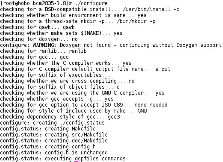
Figure 3-23. The configure script runs successfully
After this step you now need to build the application. Once again you use make to build the application. Type the following into the command prompt:
# make
That should finish quite quickly. Once it’s done, type the following to install the files:
# make install
In Figure 3-24 you can see the whole process that ran on my Raspberry Pi.
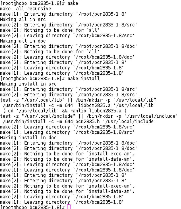
Figure 3-24. The whole build and install process
You’ve now got the tools and the headers installed, so head back into the source directory for the sensor build. This time when you run the make command you will get only one line of output. It will look something like the following with no errors:
[root@hobo pi-dht11]# make

gcc -o Adafruit_DHT Adafruit_DHT.o -std=c99 -I. -lbcm2835

[root@hobo pi-dht11]#
Do an ls on the current directory and you will now see an application called Adafruit_DHT, which is the application that will read from our sensor. The Adafruit_DHT application expects to receive two command-line options.
- The first option is what type of sensor it will be communicating with. In your case that will be the DHT11, so the first option will simply be 11.
- The last option the Adafruit_DHT application expects is the GPIO pin number. This is not the physical pin number but the logical GPIO pin reference number. Recall that you connected the data line of the DHT11 to pin P1-11: this is GPIO17.
Now that you have the required information to run the application, run it with the following command:
# ./Adafruit_DHT 11 17
This should produce something like what you see in Figure 3-25.

Figure 3-25. Output of the Adafruit_DHT application
The output of this application has three lines.
- The first line tells you what GPIO pin it’s using.
- The second line is the raw data that the application received. The last line shows the important part: the temperature and humidity.
There is one odd thing you must remember about the DHT11. The sensor itself can only ever respond to a temperature and humidity reading request every two seconds or more. If you try to ask it more frequently you will get the output you see in Figure 3-26. It’s not an error; there just are no data. You’ll notice there is no third line. Give it a few seconds and ask again.

Figure 3-26. No data received from the DHT11
The Adafruit_DHT can be run anywhere on your Raspberry Pi. I personally like to move it to /usr/local/bin as this complies with the Unix filesystem layout, but feel free to place it wherever you want. Because /usr/local/bin is in your path you won’t need to specify the full path to the binary when you run it. Here is a neat little one liner for placing the temperature and humidity readings on a separate line:
# Adafruit_DHT 11 17 | grep Temp  | tr "," "
"
This will give you the readouts on separate lines. Nice and pretty!
Now that you can read the sensors you may want a way to log the values or just to monitor them from a terminal screen. As you can see, the commands I gave you to read the two sensors are a little unfriendly to keep typing all the time. To solve this issue I will give you a little script that can read the DHT11 or the DS1820B. This script will poll the sensor at your given interval in seconds. The script has two modes of operation.
- You can run the script in monitor mode; this will just print the value of the sensor to the terminal.
- The other mode that the script supports is writing the value of the sensor to a log file.
In Listing 3-1 below you can see the code. The script has a few small assumptions. It assumes that the sensors are connected to the GPIO pins you used in this chapter and that the Adafruit_DHT binary file is in the same directory as the script itself.
Listing 3-1. . A Script to Read/Log the Sensors
#!/bin/bash
# Description : A simple bash script to monitor or log the temp sensors
# Author : Brendan Horan
SLEEP=$2
LOG=$3
function ds1820_mon {
  echo Polling DS1820 every $SLEEP seconds.
    for (( ; ; ))
    do
      echo Temperature is :
      cat /sys/bus/w1/devices/10-0008027e34ca/w1_slave  | grep t= | cut -c 30-31
      sleep $SLEEP
    done
}
function dht11_mon {
  echo Polling DHT11 every $SLEEP seconds.
    for (( ; ; ))
    do
      echo Temperature and humidity is :
      ./Adafruit_DHT 11 17 | grep Temp | tr "," "
"
      sleep $SLEEP
    done
}
function ds1820_log {
  echo Logging DS1820 to file every $SLEEP seconds. >> $LOG
    for (( ; ; ))
    do
      echo Temperature is : >> $LOG
      cat /sys/bus/w1/devices/10-0008027e34ca/w1_slave  | grep t= | cut -c 30-31 >> $LOG
      sleep $SLEEP
    done
}
function dht11_log {
  echo Logging DHT11 to file every $SLEEP seconds. >> $LOG
    for (( ; ; ))
    do
      echo Temperature and humidity is : >> $LOG
      ./Adafruit_DHT 11 17 | grep Temp | tr "," "
" >> $LOG
      sleep $SLEEP
    done
}
case $1 in
  dht11_mon)
    dht11_mon
  ;;
  ds1820_mon)
    ds1820_mon
  ;;
  dht11_log)
    dht11_log
  ;;
  ds1820_log)
    ds1820_log
  ;;
  *)
    echo --------------------------------------------------------------------------------------------
    echo
    echo  DHT11/DS1820 tool syntax.
    echo  The tool has two modes, monitor and log.
    echo  Monitor will print to screen and log will log to a file.
    echo  Script assumes the Adafruit_DHT tool is in the same directory.
    echo --------------------------------------------------------------------------------------------
    echo   -- Monitor Mode --
    echo  Monitor mode accepts two variables the name of the sensor and the polling time in seconds.
    echo  To poll the ds1820 every 5 seconds the syntax would be :
    echo  "./sensor.sh ds1820_mon 5"
    echo
    echo  To poll the DHT11 every 5 seconds the syntax would be :
    echo  "./sensor.sh dht11_mon 5"
    echo --------------------------------------------------------------------------------------------
    echo   -- Log Mode --
    echo  Log mode accepts three variables the name of the sensor, polling time and the log file name.
    echo  To log the ds1820 every 5 seconds to the syntax would be :
    echo  "./sensor.sh ds1820_log 5 /var/log/ds1820_temp &"
    echo
    echo  To log the DHT11 every 5 seconds the syntax would be :
    echo  "./sensor.sh dht11_log 5 /var/log/dht11_log &"
    echo --------------------------------------------------------------------------------------------

  ;;
esac

# END
The first time you run the script it would be a good idea to run it with no options:
# ./sensor.sh
By doing this you will be presented a help page on how to use the script. This help page will show you all the different options you can use.
For example if I wanted to monitor the DS1820B every five seconds my command would look like this:
# ./sensor.sh ds1820_mon 5
If I wanted to log the DHT11 sensor every five seconds to a log file my command would look like this:
# ./sensor.sh dht11_log 5 /var/log/dht11_sensor
Summary
In this chapter you received a detailed introduction to my love of data sheets and breadboards, starting off with how breadboards work and how they are laid out. I still suggest that you keep many breadboards around. I can guarantee you that sometimes you will have half-finished projects and pulling all the components off the board just to build something simple gets a little frustrating very quickly. This rule applies for jumper wire too. Even with a box of it I still find myself unable to find that exact cable or jumper I need. You also may have noticed my tendency to always refer you back to the data sheets when possible. I can’t stress enough how important they are. Just quickly read over them: sometimes they will save you hours of frustration.
A good example of this is the DHT11 used in this chapter. You would expect it to run fine at 3.3 V; after all it’s a very common voltage source. On the other hand 3.6 V is not common. I don’t know why or how the DHT11 came to need that as a minimum voltage, but my point is that one quick glance at your data sheets would show you this right away. The voltage range was printed on the back of the DHT11, lucky enough, but that’s not normal just like 3.6 V.
After all this I then explained the differences between the DS1820B and the DHT11. I still feel that the DS1820B is a better sensor in a lot of aspects. This is more so when you’re talking about connecting it to the Raspberry Pi and not an Arduino. The DHT11 is just far too timing-critical to work well in Linux. Sure, we got it working but I would not pick it as a sensor for use with the Raspberry Pi.
With that in mind I showed you how to access the DS1820B via the 1-wire bus. I also showed you how to make use of parasitic power. I talked about how to load the modules for the 1-wire bus and what each of them did. Once we had kernel support for the 1-wire bus I showed you how to search for and access each one of the 1-wire slaves.
In the last part of this chapter I talked about the DHT11 and how you can access it under Linux. This proved to be a bit more involved than using the built-in 1-wire bus. You were required to install additional header files to support the application that reads the DHT11. In the end the sensor was up and working, giving you temperature and humidity readings every two or more seconds. This is a little slow compared with the DS1820B. It works fine if you need to use it. The only reason I have included it is that it’s quite common to use the DHT11 with the Arduino. So you may have one lying around. Now that you have mastered data sheets and breadboards, in the next chapter you will connect a simple LCD. It will require more breadboard action and, of course, more reading of data sheets.