
![]()
Conceptual and Logical Data Model Production
I have a new philosophy. I’m only going to dread one day at a time.
—Charles M. Schulz, cartoonist best known for the comic strip Peanuts
In this chapter, we are going to really wind things up and begin to apply the skills that were covered in the previous chapters and begin creating a data model. It won’t likely be identical to the final model that gets implemented by any means, but the goal of this model will be to serve as the basis for the eventual model that will get implemented. Personally, I both love and loathe this particular step in the process because this is where things get complicated. All of the requirements and documents need to be considered. The architects and programmers from all disciplines, ideally, will be collaborating to achieve a data model and designs for the user and back-end experiences. This step is where you will also get to be the most artistic, looking for unique and interesting solutions to a variety of data needs.
Ideally, the process of requirements gathering is complete before you start the conceptual data model. Someone has interviewed all the relevant clients (and documented the interviews) and gathered artifacts ranging from previous system documentation to sketches of what the new system might look like to prototypes to whatever is available. In other projects, you may have to model to keep up with your “agile” team members, and much of the process may get done mentally and verbally. In either case, the fun part starts now: sifting through all theses artifacts and documents (and sometimes dealing with human beings directly) and discovering the database from within this cacophony.
![]() Note In reality, the process of discovery is rarely ever over. It is very difficult to get requirements perfect from any human being. In this chapter, I am going to assume the requirements are perfect for simplicity’s sake, but expect things to shift to meet requirements that were never captured.
Note In reality, the process of discovery is rarely ever over. It is very difficult to get requirements perfect from any human being. In this chapter, I am going to assume the requirements are perfect for simplicity’s sake, but expect things to shift to meet requirements that were never captured.
The ultimate purpose of the data model is to document and assist in implementing the user community’s needs for data in a very structured manner. The goal, for now, is to simply take the requirements and distill out the stuff that has a purpose in the database. In the rest of this chapter, I’ll introduce the following processes:
- Identifying entities: Looking for all the concepts that need to be modeled in the database.
- Identifying relationships between entities: Looking for natural relationships between high-level entities. Relationships between entities are what make entities useful.
- Identifying attributes and domains: Looking for the individual data points that describe the entities and how to constrain them to only real/useful values.
- Identifying business rules: Looking for the boundaries that are applied to the data in the system that go beyond the domains of a single attribute.
- Identifying fundamental processes: Looking for different processes (code and programs) that the client tends to execute that are fundamental to its business.
The result from the first two steps listed is commonly called the conceptual model. The conceptual model describes the overall structure of the data model you will be creating so you can checkpoint the process before you get too deep. You will use the conceptual model as a communication device because it has enough structure to show the customer and test that you can meet the requirements, but not so much that a great investment has been made.
Once everyone feels like the entities and relationships make sense, you will use the conceptual model as the basis of the logical model by filling in attributes and keys, discovering business rules, and making structural changes to arrive at a picture of the data needs of the client. By the time you have completed this task, you should have a strong sense that the user has what they need.
This logical model will then go through refinement by following the principles of normalization, which will be covered in the next chapter, to produce a complete model that is ready to be finalized as a physical data model and implemented as a set of tables, columns, constraints, triggers, and all of the fun stuff that you probably bought this book to read about.
In this chapter, we will go through the steps required to produce an unrefined, early logical model, using a one-page set of requirements as the basis of our design that will be presented in the first section. For those readers who are new to database design, this deliberate method of working though the design to build this model is a great way to help you follow the best possible process. Take care that I said “new to database design,” not “new to creating and manipulating tables in SQL Server.” Although these two things are interrelated, they are distinct and different steps of the same process.
After some experience, you may never take the time to produce a model exactly like I will discuss in this chapter. In all likelihood, you will perform a lot of these steps mentally and will combine them with some of the refinement processes we will work on in the later chapters. Such an approach is natural and actually a very normal thing. You should know, however, that working though the database design process is a lot like working through a complex math problem, in that you are solving a big problem and showing your work is never a bad thing. As a student in a lot of math classes, I was always amazed that showing your work is usually done more by the advanced mathematician than by anyone else. Advanced people know that writing things down avoids errors, and when errors do occur, you can look back and figure out why. This isn’t to say that you will never want to go directly from requirements to a physical model. However, the more you know about how a proper database should look, the more likely you are to try to force the next model into a certain mold, sometimes without listening to what the customer needs first.
Example Scenario
Throughout the rest of the chapter, the following example piece of documentation will be used as the basis of our examples. In a real system, this might be just a single piece of documentation that has been gathered among hundreds. (It always amazes me how much useful information you can get from a few paragraphs, though to be fair I did write—and rewrite—this example more than a couple of times.)
The client manages a couple of dental offices. One is called the Chelsea Office, the other the Downtown Office. The client needs the system to manage its patients and appointments, alerting the patients when and where their appointments occur, either by e-mail or by phone, and then assisting in the selection of new appointments. The client wants to be able to keep up with the records of all the patients’ appointments without having to maintain lots of files. The dentists might spend time at each of the offices throughout the week.
For each appointment, the client needs to have everything documented that went on and then invoice the patient’s insurance, if he or she has insurance (otherwise the patient pays). Invoices should be sent within one week after the appointment. Each patient should be able to be associated with other patients in a family for insurance and appointment purposes. We will need to have an address, a phone number (home, mobile, and/or office), and optionally an e-mail address associated with each family, and possibly each patient if the client desires. Currently, the client uses a patient number in its computer system that corresponds to a particular folder that has the patient’s records.
The system needs to track and manage several dentists and quite a few dental hygienists who the client needs to allocate to each appointment as well. The client also wants to keep up with its supplies, such as sample toothpastes, toothbrushes, and floss, as well as dental supplies. The client has had problems in the past keeping up with when it’s about to run out of supplies and wants this system to take care of this for both locations. For the dental supplies, we need to track usage by employee, especially any changes made in the database to patient records.
Through each of the following sections, our goal will be to acquire all the pieces of information that need to be stored in our new database system. Sounds simple enough, eh? Well, although it’s much easier than it might seem, it takes time and effort (two things every technology professional has in abundance, right?).
The exercise/process provided in this chapter will be similar to what you may go through with a real system design effort, but it is very much simplified. The point of this chapter is to give you a feeling for how to extract a data model from requirements. The requirements in this section are very much a subset of what is needed to implement the full system that this dental office will need. In the coming chapters, I will present smaller examples to demonstrate independent concepts in modeling that have been trimmed down to only the concepts needed.
Building the Conceptual Model
The conceptual model is all about the big picture of the model. What is being modeled? How should the resulting database look? Details like how data will be stored should be left alone for now. We want to know, “What are the concepts the customer wants to store data about?” Customers, Dentists, Insurance Policies, etc. and how they are related are the essential parts of this process. Customers have Insurance Policies, and other relationships give you the skeleton of the database.
If you have ever been involved with building a building of some sort, there are many iterations in the process. You start by sketching out the basic structure that the customer wants, and refine it over and over until you have a solid understanding of what the customer wants. You may not know where the building will be built, probably don’t know what the materials will be, and certainly have no idea where the plugs in the kitchen will be located. Everything is changeable, but usually once the design shows the concepts of the final building and the customer approves it, the foundation for success has been laid.
In the database design process, our goal will be to understand the types of data the customer needs to store, and how things are related to one another. When we complete the conceptual model, we will have the framework of our database completed, and will be ready to fill in the details.
Entities generally represent people, places, objects, ideas, or things, referred to grammatically as nouns. While it isn’t really critical for the final design to put every noun into a specific bucket of types, doing so can be useful in identifying patterns of attributes later. People usually have names, phone numbers, and so on. Places have an address that identifies an actual location.
It isn’t critical to identify that an entity is a person, place, object, or idea, and in the final database, it won’t make a bit of difference. However, in the next major section of this chapter, we will use these types as clues to some attribute needs and to keep you on the lookout for additional bits of information along the way. So I try to make a habit of classifying entities as people, places, and objects for later in the process. For example, our dental office includes the following:
- People: A patient, a doctor, a hygienist
- Places: Dental office, patient’s home, hospital
- Objects: A dental tool, stickers for the kids, toothpaste
- Ideas: A document, insurance, a group (such as a security group for an application), the list of services provided, and so on
There’s clearly overlap in several of the categories (for example, a building is a “place” or an “object”). Don’t be surprised if some objects fit into several of the subcategories below them that I will introduce. Let’s look at each of these types of entities and see what kinds of things can be discovered from the documentation sample in each of the aforementioned entity types.
![]() Tip The way an entity is implemented in a table might be different from your initial expectation. When building the initial design, you want the document to come initially from what the user wants. Then, you’ll fit what the user wants into a proper table design later in the process. Especially during the conceptual modeling phase, a change in the design is still a click and drag away.
Tip The way an entity is implemented in a table might be different from your initial expectation. When building the initial design, you want the document to come initially from what the user wants. Then, you’ll fit what the user wants into a proper table design later in the process. Especially during the conceptual modeling phase, a change in the design is still a click and drag away.
Nearly every database needs to store information about people. Most databases have at least some notion of user (generally thought of as people, though not always, so don’t assume and end up with your actual users required to create a user with a first name of “Alarm” and last name “System”). As far as real people are concerned, a database might need to store information about many different types of people. For instance, a school’s database might have a student entity, a teacher entity, and an administrator entity.
In our example, three people entities can be found by reading through our example scenario—patients, dentists, and hygienists:
- . . . the system to manage its patients. . .
and
- . . . manage several dentists and quite a few dental hygienists. . .
Patients are clearly people, as are dentists and hygienists (yes, that crazy person wearing a mask that is digging into your gums with a pitchfork is actually a person). One additional person type entity is also found here:
- . . . we need to track usage by employee. . .
Dentists and hygienists have already been mentioned. It’s clear that they’ll be employees as well. For now, unless you can clearly discern that one entity is exactly the same thing as another, just document that there are four entities: patients, hygienists, dentists, and employees. Our model then starts out as shown in Figure 4-1.

Figure 4-1. Four entities that make up our initial model
![]() Tip Note that I have started with giving each entity a simple surrogate key attribute. In the conceptual model, we don’t care about the existence of a key, but as we reach the next step with regard to relationships, the surrogate key will migrate from table to table to give a clear picture of the lineage of ownership in the model. Feel free to leave the surrogate key off if you want, especially if it gets in the way of communication, because laypeople sometimes get hung up over keys and key structures.
Tip Note that I have started with giving each entity a simple surrogate key attribute. In the conceptual model, we don’t care about the existence of a key, but as we reach the next step with regard to relationships, the surrogate key will migrate from table to table to give a clear picture of the lineage of ownership in the model. Feel free to leave the surrogate key off if you want, especially if it gets in the way of communication, because laypeople sometimes get hung up over keys and key structures.
Users will want to store information relative to many different types of places. One obvious place entity is in our sample set of notes:
- . . . manages a couple of dental offices. . .
From the fact that dental offices are places, later we’ll be able to expect that there’s address information about the offices, and probably phone numbers, staffing concerns, and so on that the user may be interested in capturing information about. We also get the idea from the requirements that the two offices aren’t located very close to each other, so there might be business rules about having appointments at different offices or to prevent the situation in which a dentist might be scheduled at two offices at one time. “Expecting” is just slightly informed guessing, so verify all expectations with the client.
I add the Office entity to the model, as shown in Figure 4-2.

Figure 4-2. Added Office as an entity
![]() Note To show progress in the model as it relates to the narrative in the book, in the models, things that haven’t changed from the previous step in the process are in gray, while new additions are unshaded.
Note To show progress in the model as it relates to the narrative in the book, in the models, things that haven’t changed from the previous step in the process are in gray, while new additions are unshaded.
Objects refer primarily to physical items. In our example, there are a few different objects:
- . . . with its supplies, such as sample toothpastes, toothbrushes, and floss, as well as dental supplies. . .
Supplies, such as sample toothpastes, toothbrushes, and floss, as well as dental supplies, are all things that the client needs to run its business. Obviously, most of the supplies will be simple, and the client won’t need to store a large amount of descriptive information about them. For example, it’s possible to come up with a pretty intense list of things you might know about something as simple as a tube of toothpaste:
- Tube size: Perhaps the length of the tube or the amount in grams
- Brand: Colgate, Crest, or some other brand/lack of brand (which should not feel slighted by the lack of inclusion in my book)
- Format: Metal or plastic tube, pump, and so on
- Flavor: Mint, bubble gum (the nastiest of all flavors), cinnamon, and orange
- Manufacturer information: Batch number, expiration date, and so on
We could go on and on coming up with more and more attributes of a tube of toothpaste, but it’s unlikely that the users will have a business need for this information, because they probably just have a box of whatever samples they have been bribed with from the dental companies and give them out to their patients (to make them feel better about the metal against enamel experience they have just gone through).
One of the first, extremely important lessons about over-engineering starts right here. At this point, we need to apply selective ignorance to the process and ignore the different attributes of things that have no specifically stated business interest. If you think that the information is useful, it is probably a good idea to drill into the client’s process to make sure what they actually want, but don’t assume that just because you could design the database to store something that that makes it necessary, or that the client will change their processes to match your design. If you have good ideas, they might change, but most companies have what seem like insane business rules for reasons that make sense to them and they can reasonably defend them.
Only one entity is necessary—Supply—but document that “Examples given were sample items, such as toothpaste or toothbrushes, plus there was mention of dental supplies. These supplies are the ones that the dentist and hygienists use to perform their job.” This documentation you write will be important later when you are wondering what kind of supplies are being referenced.
Catching up the model, I add the Supply entity to the model, as shown in Figure 4-3.
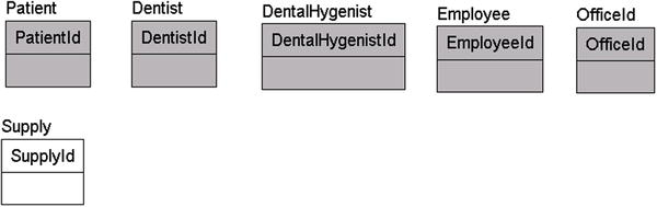
Figure 4-3. Added the Supply entity
No law or rule requires that entities should represent real objects or even something that might exist physically. At this stage of discovery, you need to consider information on objects that the user wants to store that don’t fit the already established “people,” “places,” and “objects” categories and that might or might not be physical objects.
For example, consider the following:
- . . . and then invoice the patient’s insurance, if he or she has insurance (otherwise the patient pays). . .
Insurance is an obvious important entity as the medical universe rotates around it. Another entity name looks like a verb rather than a noun in the phrase “patient pays.” From this, we can infer that there might be some form of Payment entity to deal with.
![]() Tip Not all entities will be adorned with a sign flashing “Yoo-hoo, I am an entity!” A lot of the time, you’ll have to read what has been documented over and over and sniff it out like a pig on a truffle.
Tip Not all entities will be adorned with a sign flashing “Yoo-hoo, I am an entity!” A lot of the time, you’ll have to read what has been documented over and over and sniff it out like a pig on a truffle.
The model now looks like Figure 4-4.

Figure 4-4. Added the Insurance and Payment entities
Documents
A document represents some piece of information that is captured and transported in one package. The classic example is a piece of paper that has been written on documenting a bill that needs to be paid. If you have a computer and/or have used the Interwebs at all, you probably know that the notion that a document has to be a physical piece of paper is as antiquated as borrowing a cup of sugar from your neighbor to make cupcakes to take to a child’s school (have some birthday celery, classmates!). And even for a paper document, what if someone makes a copy of the piece of paper? Does that mean there are two documents, or are they both the same document? Usually, it isn’t the case, but sometimes people do need to track physical pieces of paper and, just as often, versions and revisions of a document.
In the requirements for our new system, we have a few examples of documents that need to be dealt with. First up, we have
- . . . and then invoice the patient’s insurance, if he or she has insurance (otherwise the patient pays). . .
Invoices are pieces of paper (or e-mails) that are sent to a customer after the services have been rendered. However, no mention was made as to how invoices are delivered. They could be e-mailed or postal mailed—it isn’t clear—nor would it be prudent for the database design to force it to be done either way unless there is a specific business rule governing the method of or tracking the delivery (and even still things change faster than database implementations, so be wary of hard-coding business rules in a nonchangeable manner). At this point, just identify the entities (Invoice in this instance) and move along; again, it usually isn’t worth it to spend too much time guessing how the data will be used.
Next up, we have the following:
- . . . appointments, alerting the patients when and where their appointments occur, either by e-mail or by phone. . .
This type of document almost certainly isn’t delivered by paper but by an e-mail message or phone call. The e-mail is also used as part of another entity, Alert. The alert can be either an e-mail or a phone alert. You may also be thinking, “Is the alert really something that is stored?” Maybe or maybe not, but it is probably likely that when the administrative assistants call and alert the patient that they have an appointment, a record of this interaction would be made. Then, when the person misses their appointment, they can say, “We called you, e-mailed you, and texted you on June 14th to no avail using the number that you provided us!” It may also be important that you track the addresses that were used for alerts, in case the primary numbers change so you can know what address was actually alerted, but more on that later in the chapter.
![]() Note If you are alert, you probably are thinking that Appointment, Email, and Phone are all entity possibilities, and you would be right. In my teaching process here, I am looking at the types one at a time to make a point. In the real process, you would just look for nouns linearly through the text and enhancing in a very set manner so this chapter isn’t larger than my allocation of pages for the entire book.
Note If you are alert, you probably are thinking that Appointment, Email, and Phone are all entity possibilities, and you would be right. In my teaching process here, I am looking at the types one at a time to make a point. In the real process, you would just look for nouns linearly through the text and enhancing in a very set manner so this chapter isn’t larger than my allocation of pages for the entire book.
Next, we add the Invoice and Alert entities to the model, as shown in Figure 4-5.

Figure 4-5. Added the Alert and Invoice entities
Another idea-type entity is a group of things, or more technically, a grouping of entities. For example, you might have a club that has members or certain types of products that make up a grouping that seems more than just a simple attribute. In our sample, we have one such entity:
- Each patient should be able to be associated with other patients in a family for insurance and appointment purposes.
Although a person’s family could be an attribute of the person, it’s likely more than that. So, we add a Family entity, as shown in Figure 4-6. Remember that anything added to the conceptual model can be removed later.

Figure 4-6. Added the Family entity
Other Entities
The following sections outline some additional common objects that are perhaps not as obvious as the ones that have been presented. They don’t always fit a simple categorization, but they’re pretty straightforward.
Audit Trails
Audit trails, generally speaking, are used to track changes to the database. You might know that the RDBMS uses a log to track changes, but this is off-limits to the average user. So, in cases where the user wants to keep up with who does what, entities need to be modeled to represent these logs. They could be analogous to a sign-in/sign-out sheet, an old-fashioned library card in the back of the book, or just a list of things that went on in any order.
Consider the following example:
- For the dental supplies, we need to track usage by employee, especially any changes made in the database to the patient records.
In this case, the client clearly is keen to keep up with the kinds of materials that are being used by each of its employees. Perhaps a guess can be made that the user needs to be documented when dental supplies are taken (the difference between dental supplies and nondental supplies will certainly have to be discussed in due time). Also, it isn’t necessary at this time that the needed logging be done totally on a computer, or even by using a computer at all.
A second example of an audit trail is as follows:
- For the dental supplies, we need to track usage by employee, and especially any changes made in the database to the patient records.
A typical entity that you need to define is the audit trail or a log of database activity, and this entity is especially important when the data is sensitive. An audit trail isn’t a normal type of entity, in that it stores no data that the user directly manipulates, and the final design will generally be deferred to the implementation design stage, although it is common to have specific requirements for what sorts of information need to be captured in the audit. Generally, the primary kinds of entities to be concerned with at this point are those that users wish to store in directly.
Event entities generally represent verbs or actions:
- For each appointment, the client needs to have everything documented that went on. . .
An appointment is an event, in that it’s used to record information about when patients come to the office to be tortured for not flossing regularly enough. For most events, appointments included, it’s important to have a schedule of when the event is (or was) and where the event will or did occur. It’s also not uncommon to want to have data that documents an event’s occurrence (what was done, how many people attended, and so on). Hence, many event entities will be tightly related to some form of document entity. In our example, appointments are more than likely scheduled for the future, along with information about the expected activities (cleaning, x-rays, etc.), and when the appointment occurs, a record is made of what services were actually performed so that the dentist can get paid. Generally speaking, there are all sorts of events to look for in any system, such as meter readings for a utility company, weather readings for a sensor, equipment measurements, phone calls, and so on.
The last of the entity types to examine at this stage is a record or journal of activities. Note that I mean “record” in a nondatabase sort of way. A record could be any kind of activity that a user might previously have recorded on paper. In our example, the user wants to keep a record of each visit:
- The client wants to be able to keep up with the records of all the patients’ appointments without having to maintain lots of files.
Keeping information in a centralized database is one of the main advantages of building database systems: eliminating paper files and making data more accessible, particularly for future data mining. How many times must I tell the doctor what medicines I’m taking, all because her files are insane clutters used to cover her billing process, rather than being a useful document of my history? What if I forget one that another doctor prescribed, and it interacts strongly with another drug? All of this duplication of asking me what drugs I take is great for covering the doctor’s and pharmacy’s hides, but by leveraging an electronic database that is connected to other doctor and pharmacy records, the information that people are constantly gathering comes alive, and trends can be seen instantly in ways it would take hours to see on paper. “Hmm, after your primary doctor started you taking Vitamin Q daily, when the time between cleanings is more than 10 months from the previous one, you have gotten a cavity!” (Or perhaps even more importantly, given enough data from enough people, we can finally get a good idea of what course of drugs cures diseases, rather than simply using small-scale experiments. Keep in mind that the more data you can get into your database, the more likely that data can be used for data mining at some time in the future.) Of course, putting too much information in a centralized location makes security all that much more important as well, so it is a double-edged sword as well (we will talk security in Chapter 9, but suffice it to say that it is not a trivial issue).
The model after the changes looks like Figure 4-7.

Figure 4-7. Added the Appointment, DentalSupplyAudit, and PatientRecord entities
Careful now, as you are probably jumping to a quick conclusion that a payment record is just an amalgamation of their invoices, insurance information, x-rays, and so on. This is 100% true, and I will admit right now that the PatientRecord table is probably a screen in the application where each of the related rows would be located. During early conceptual modeling, it is generally best to just put it on the model as you have found it and do the refinement later when you feel you have everything needed to model it right. This is especially true when you are working from documents and not with the users directly, a practice that is becoming less prevalent, but not completely extinct.
Entity Recap
So far, we’ve discovered the list of preliminary entities shown in Table 4-1. It makes a pretty weak model, but this will change in the next few sections as we begin adding relationships between entities and the attributes. Before progressing any further, stop, define, and document the entities as shown in Table 4-1.
Table 4-1. Entity Listing
|
Entity |
Type |
Description |
|---|---|---|
|
Patient |
People |
The people who are the customers of the dental office. Services are performed, supplies are used, and patients are billed for them. |
|
Family |
Idea |
A group of patients grouped together for convenience. |
|
Dentist |
People |
People who do the most important work at the dental office. Several dentists are working for the client’s practice. |
|
DentalHygienist |
People |
People who do the routine work for the dentist. There are quite a few more hygienists than dentists. (Note: Check with client to see whether there are guidelines for the number of hygienists per dentist. Might be needed for setting appointments.) |
|
Employee |
People |
Any person who works at the dental office. Dentists and hygienists are clearly types of employees. |
|
Office |
Places |
Locations where the dentists do their business. They have multiple offices to deal with and schedule patients for. |
|
Supply |
Objects |
Supplies for the running of the dental operations of the office. Examples given were sample items, such as toothpaste or toothbrushes, plus there was mention of dental supplies as the supplies that the dentists and hygienists use to perform their jobs. |
|
Insurance |
Idea |
Used by patients to pay for the dental services rendered. |
|
Payment |
Idea |
Money received from insurance or patients (or both) to pay for services. |
|
Invoice |
Document |
A document sent to the patient or insurance company explaining how much money is required to pay for services. |
|
Alert |
Document |
A communication made to tell patient of an impending appointment. |
|
DentalSupplyAudit |
Audit Trail |
Used to track the usage of dental supplies. |
|
Appointment |
Event |
The event of a patient coming in and having some dental work done. |
|
PatientRecord |
Record |
All the pertinent information about a patient, much like a patient’s folder in any doctor’s office. |
The descriptions are based on the facts that have been derived from the preliminary documentation. Note that the entities that have been specified are directly represented in the customer’s documentation.
Are these all of the entities? Maybe, maybe not, but it is the set we have discovered after the first design pass. During a real project you will frequently discover new entities and delete an entity or two that you thought would be necessary. It is not a perfect process in most cases, because you will be constantly learning the needs of the users.
![]() Note The conceptual modeling phase is where knowledge of your clients’ type of business can help and hinder you. On one hand, it helps you see what they want quickly, but at the same time it can lead you to jump to conclusions based on “how things were done when I did something similar for another client.” Every client is unique and has its own way of doing stuff. The most important tools you will need to use are your eyes and ears.
Note The conceptual modeling phase is where knowledge of your clients’ type of business can help and hinder you. On one hand, it helps you see what they want quickly, but at the same time it can lead you to jump to conclusions based on “how things were done when I did something similar for another client.” Every client is unique and has its own way of doing stuff. The most important tools you will need to use are your eyes and ears.
Identifying Relationships Between Entities
Next, we will look for the ways that the entities relate to one another, which will then be translated to relationships between the entities on the model. The idea here is to find how each of the entities will work with one another to solve the client’s needs. I’ll start first with the one-to-N type of relationships and then cover the many-to-many. It’s also important to consider elementary relationships that aren’t directly mentioned in your requirements. Just realize that the user knows what they want the system to be like, and you are going to go back over their requests and fill in the blanks later.
In each of the one-to-N relationships, the table that is the “one” table in the relationship is considered the parent, and the “N” is the child or children rows. While the one-to-N relationship is going to be the only relationship you will implement in your relational model, a lot of the natural relationships you will discover in the model may in fact turn out to be many-to-many relationships. It is important to really scrutinize the cardinality of all relationships you model so as not to limit future design considerations by missing something that is very natural to the process. To make it more real, instead of thinking about a mechanical term like one-to-N, we will break it down in to a couple of types of relationships:
- Simple: One instance is related to one or more child instances. The primary point of identifying relationships this way is to form an association between two entity rows.
- Is a: Unlike the previous classification, when we think of an is-a relationship, usually the two related items are the same thing, often meaning that one table is a more generic version of the other. A manager is an employee, for example. In the data modeling chapter (Chapter 3), we referred to this type of relationship as a categorization relationship.
I’ll present examples of each type in the next couple sections.
Simple Relationships
In this section, I discuss some of the types of associations that you might uncover along the way as you are modeling relationships. Another common term for a simple relationships is often a “has-a” relationship, so named because as you start to give verb phrase/names to relationships, you will find it very easy to say “has a” for almost every relationship. In fact, a common mistake by modelers is to end up using “has a” as the verb phrase for too many of their parent-child relationships, which degrades the value of the verb phrase (sometimes, however, it really just is the best verb phrase).
In this section, I will discuss a few example type relationships that you will come in contact with quite often. The following are different types of simple relationships:
- Connection: An association association between two things, like a person and their driver’s license or car. This is the most generic of all relationships, and will generally cover any sort of ownership or association between entities.
- Transaction: more generically, this could be thought of as an interaction relationship. For example, a customer pays a bill or makes a phone call, so an account is credited/debited money through transactions.
- Multivalued attribute: In an object implemented in an object-oriented language, one can have arrays for attributes, but in a relational database, as discussed in Chapter 1, all attributes must be atomic/scalar values (or at least should be) in terms of what data we will use in relational queries. So when we design, say, an invoice entity, we don’t put all of the line items in the same table; we make a new table, commonly called invoiceLineItem. Another common example is storing customers’ preferences. Unless they can only have a single preference, a new table is required for each.
- Domain: A type of relationship that you may possibly uncover in early modeling is a domain type. It is used to implement the domain for an attribute where more than a single attribute seems useful. I will not demonstrate this relationship type in the chapter, but we will look at domain relationships in later chapters (they are most commonly used as an implementation tool).
In the next few sections, I will use these four types of relationships to classify and pick out some of the relationship types discovered in our dental office example.
Connection
In our example requirements paragraph, consider the following:
- . . . then invoice the patient’s insurance, if he or she has insurance. . .
In this case, the relationship is between the Patient and Insurance entities. It’s an optional relationship, because it says “if he or she has insurance.” Add the following relationship to the model, as shown in Figure 4-8.

Figure 4-8. Added the relationship between the Patient and Insurance entities
Another example of a has-a relationship follows:
- Each patient should be able to be associated with other patients in a family for insurance and appointment purposes.
In this case, we identify that a family has patients. Although this sounds a bit odd, it makes perfect sense in the context of a medical office. Instead of maintaining ten different insurance policies for each member of a family of ten, the client wants to have a single one where possible. So, we add a relationship between family and patient, stating that a family instance may have multiple patient instances. Note too that we make it an optional relationship because a patient isn’t required to have insurance.
That the family is covered by insurance is also a possible relationship in Figure 4-9. It has already been specified that patients have insurance. This isn’t unlikely, because even if a person’s family has insurance, one of the members might have an alternative insurance plan. It also doesn’t contradict our earlier notion that patients have insurance, although it does give the client two different paths to identify the insurance. This isn’t necessarily a problem, but when two insurance policies exist, you might have to implement business rule logic to decide which one takes precedence. Again, this is something to discuss with the client and probably not something to start making up.

Figure 4-9. Relationships added among the Patient, Insurance, and Family entities
Here’s another example of connective relationship, shown in Figure 4-10:
- . . . dental offices. . .The client needs the system to manage its patients and appointments. . .

Figure 4-10. Relationship added between the Office and Appointment entities
In this case, make note that each dental office will have appointments. Clearly, an appointment can be for only a single dental office, so this is not a many-to-many relationship. One of the attributes of an event type of entity is often a location. It’s unclear at this point whether a patient comes to only one of the offices or whether the patient can float between offices. However, it is certain that appointments must be made at the office, so the relationship between Office and Appointment is required. Now add the relationship shown in Figure 4-10.
Transactions
Transactions are probably the most common type of relationships in databases. Almost every database will have some way of recording interactions with another entity instance. For example, some very common transaction are simply customers making purchases, payments, and so on. I can’t imagine a useful database that only has customer and product data with transactional information recorded elsewhere.
In our database, we have one very obvious transaction:
- . . . if he or she has insurance (otherwise the patient pays). Invoices should be sent. . .
We identified Patient and Payment entities earlier, so we add a relationship to represent a patient making a payment. Figure 4-11 shows the new relationship.

Figure 4-11. Relationship added between the Patient and Appointment entities
Multivalued Attributes and Domains
During the early phases of modeling, it is far less likely to discover multivalued attribute and domain relationships naturally than any other types. The reason is that users generally think in large concepts, such as objects. In our model, so far, we identified a couple of places where we are likely to expand the entities to cover array types that may not strictly be written in requirements, particularly true when the requirements are written by end users.
For example, in terms of multivalued attributes: Invoices have invoice line items; Appointments have lists of Actions that will be taken such as cleaning, taking x-rays, and drilling; Payments can have multiple payment sources. For domain relationships, you can think of status values for most of the aforementioned entities. While a domain of “Active” and “Inactive” may not elevate to the need of a domain table, if we also want to associate a description with this value (“Active patients for more than 5 years get better goodies”), or perhaps include some process to take when the patient is in the status, having a table of possible status values would make that possible. In some cases, these types of complex domains may be shown on the conceptual model, but when a designer does so, it usually is because the designer is overcomplicating the process of conceptual modeling.
As such, I won’t come up with any examples of domain or multivalued attribute relationships in the example paragraphs, but we will cover this topic in more depth in Chapter 8 when I cover modeling patterns for implementation.
The Is-A Relationship
The major idea behind an is-a relationship is that the child entity in the relationship extends the parent. For example, cars, trucks, RVs, and so on, are all types of vehicles, so a car is a vehicle. The cardinality of this relationship is always one-to-one, because the child entity simply contains more specific information that qualifies this extended relationship. There would be some information that’s common to each of the child entities (stored as attributes of the parent entity) but also other information that’s specific to each child entity (stored as attributes of the child entity).
In our example text, the following snippets exist:
- . . . manage several dentists and quite a few dental hygienists who the client. . .
and
- . . . track usage by employee, especially. . .
From these statements, you can reasonably infer that there are three entities, and there’s a relationship between them. A dentist is an employee, as is a dental hygienist. There are possibly other employees for whom the system needs to track supply usage as well, but none listed at this point. Figure 4-12 represents this relationship, which is modeled using the subtype relationship type. Note that this is modeled as a complete subtype, meaning every Employee instance would either have a corresponding Dentist or DentalHygenist instance.

Figure 4-12. Identified subtyped relationship between the Employee, Dentist, and DentalHygienist entities
![]() Note Because the subtype manifests itself as a one-to-one identifying relationship (recall from Chapter 3 that the Z on the relationship line indicates a one-to-one relationship), separate keys for the Dentist and DentalHygienist entities aren’t needed.
Note Because the subtype manifests itself as a one-to-one identifying relationship (recall from Chapter 3 that the Z on the relationship line indicates a one-to-one relationship), separate keys for the Dentist and DentalHygienist entities aren’t needed.
This use of keys can be confusing in the implementation, since you might have relationships at any of the three table levels and since the key will have the same name. These kinds of issues are why you maintain a data model for the user to view as needed to understand the relationships between tables.
Many-to-Many Relationships
Many-to-many relationships are far more prevalent than you might think. In fact, as you refine the model, a great number of relationships may end up being many-to-many relationships as the real relationship between entities is realized. However, early in the design process, only a few obvious many-to-many relationships might be recognized. In our example, one is obvious:
- The dentists might spend time at each of the offices throughout the week.
In this case, each of the dentists can work at more than one dental office. A one-to-many relationship won’t suffice; it’s wrong to state that one dentist can work at many dental offices, because this implies that each dental office has only one dentist. The opposite, that one office can support many dentists, implies dentists work at only one office. Hence, this is a many-to-many relationship (see Figure 4-13).
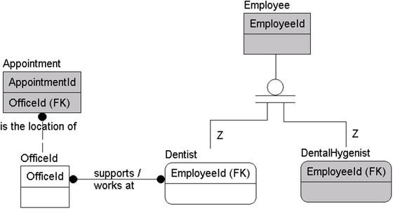
Figure 4-13. Added a many-to-many relationship between Dentist and Office
I know what most of you are thinking, “Hey, what about dentists being associated with appointments, and the same for dental hygienists?” First off, that is good thinking. When you get back to your client, you probably will want to discuss that issue with them (and hopefully your requirements gatherer will have that discussion immediately. . . mine did not!). For now, we document what the requirements ask for, and later, we ask the analyst and the client if they want to track that information. It could be that, in this iteration of the product, they just want to know where the dentist is so they can use that information when making manual appointments. Again, we are not to read minds but to do what the client wants in the best way possible.
There is an additional many-to-many relationship that can be identified:
- . . . dental supplies, we need to track usage by employee . . .
This quote says that multiple employees can use different types of supplies, and for every dental supply, multiple types of employees can use them. However, it’s possible that controls might be required to manage the types of dental supplies that each employee might use, especially if some of the supplies are regulated in some way (such as narcotics).
The relationship shown in Figure 4-14 is added.

Figure 4-14. Added a many-to-many relationship between the Supply and Employee entities
I’m also going to remove the DentalSupplyAudit entity, because it’s becoming clear that this entity is a report, and we will figure out how to solve this need later in the process. What we know from here is that employees use supplies, and we need to capture that that is happening.
Figure 4-15 shows the model so far.

Figure 4-15. The model so far
There are other relationships in the text that I won’t cover explicitly, but I’ve documented them in the descriptions in Table 4-2, which is followed by the model with relationships identified and the definitions of the relationships in our documentation (note that the relationship is documented at the parent only).
Table 4-2. Initial Relationship Documentation
|
Entity |
Type |
Description |
|---|---|---|
|
Patient |
People |
The people who are the customers of the dental office. Services are performed, supplies are used, and the patient is billed for these services. |
|
Is covered by Insurance |
Identifies when the patient has personal insurance. | |
|
Is reminded by Alerts |
Alerts are sent to patients to remind them of their appointments. | |
|
Is scheduled via Appointments |
Appointments need to have one patient. | |
|
Is billed with Invoices |
Patients are charged for appointments via an invoice. | |
|
Makes Payment |
Patients make payments for invoices they receive. | |
|
Has activity listed in PatientRecord |
Activities that happen in the doctor’s office. | |
|
Family |
Idea |
A group of patients grouped together for convenience. |
|
Has family members as Patients |
A family consists of multiple patients. | |
|
Is covered by Insurance |
Identifies when there’s coverage for the entire family. | |
|
Dentist |
People |
People who do the most skilled work at the dental office. Several dentists work for the client’s practice. |
|
Works at many Offices |
Dentists can work at multiple offices. | |
|
Is an Employee |
Dentists have some of the attributes of all employees. | |
|
Works during Appointments |
Appointments might require the services of one dentist. | |
|
DentalHygienist |
People |
People who do the routine work for the dentist. There are quite a few more hygienists than dentists. (Note: Check with client to see if there are guidelines for the number of hygienists per dentist. Might be needed for setting appointments.) |
|
Is an Employee |
Hygienists have some of the attributes of all employees. | |
|
Has Appointments |
All appointments need to have at least one hygienist. | |
|
Employee |
People |
Any person who works at the dental office. Dentists and hygienists are clearly types of employees. |
|
Use Supplies |
Employees use supplies for various reasons. | |
|
Office |
Places |
Locations where the dentists do their business. They have multiple offices to deal with and schedule patients for. |
|
Is the location of Appointments |
Appointments are made for a single office. | |
|
Supply |
Objects |
Supplies for the running of the dental operations of the office. Examples given were sample items, such as toothpaste or toothbrushes, plus there was mention of dental supplies as the supplies that the dentists and hygienists use to perform their jobs. |
|
Are used by many Employees |
Employees use supplies for various reasons. | |
|
Insurance |
Idea |
Used by patients to pay for the dental services rendered. |
|
Payment |
Idea |
Money received from insurance or patients (or both) to pay for services. |
|
Invoice |
Document |
A document sent to the patient or insurance company explaining how much money is required to pay for services. |
|
Has Payments |
Payments are usually made to cover costs of the invoice (some payments are for other reasons). | |
|
Alert |
Document |
E-mail or phone call made to tell patient of an impending appointment. |
|
Appointment |
Event |
The event of a patient coming in and having some dental work done. |
|
PatientRecord |
Record |
All the pertinent information about a patient, much like a patient’s chart in any doctor’s office. |
Figure 4-16 shows how the model has progressed.

Figure 4-16. The final conceptual model
You can see, at this point, that the conceptual model has really gelled, and you can get a feel for what the final model might look like. In the next section, we will start adding attributes to the tables, and the model will truly start to take form. It is not 100 percent complete, and you could probably find a few things that you really want to add or change (for example, the fact that Insurance pays Invoice stands out is a definite possibility). However, note that we are trying our best in this phase of the design (certainly in this exercise) to avoid adding value/information to the model. That is part of the process that comes later as you fill in the holes in the documentation that you are given from the client.
Bear in mind that the only attributes that I have included on this model were used as a method to show lineage. The only time I used any role names for attributes was in the final model, when I related the two subtypes of Employee to the Appointment entity, as shown in Figure 4-17.

Figure 4-17. Appointment entity with a role named EmployeeRelationship
I related the two subtypes to the Appointment entity to make it clear what the role of each relationship was for, rather than having the generic EmployeeId in the table for both relationships. Again, even the use of any sort of key is not a standard conceptual model construct, but without relationship attributes, the model seems sterile and also tends to hide lineage from entity to entity.
The Appointment entity is the best example in my tiny example diagram of how the model shows you some basic makeup of the entity, as we can now see that for an appointment, we need an office, a patient, a hygienist, and sometimes a dentist available (since the relationship is optional). None of these things really defines an appointment, so it is still an independent entity, but those attributes are critical.
Before stamping “done” on the conceptual model, this is the time to take one last trip through the requirements and make sure that they can be met by the entities in your model. We will not spend too much time here in the text covering what this means, because it is basically the same process you have already gone through, iterating until you don’t find anything that needs to be changed. Earlier in the chapter we took the following requirement:
- . . .then invoice the patient’s insurance, if he or she has insurance. . .
Now we need to make sure that if something has changed with the entity we had created that it still meets the need. The test is likely as simple as a listing like:
- Create a Patient instance.
- Create a related Insurance instance to represent their insurance policy.
Seeing that every requirement can be met at a high level will help you see if your model is prepared to meet all of the requirements that you have expected it to. It is possible that you may have changed an entity to something that will no longer meet the requirements, but you are still at a great place in the process where changes require zero coding.
Building the Logical Model
In this section, with the conceptual model completed and tested, the next steps in the modeling process are going to be considerably easier. Unlike the conceptual model, where you focus on the big picture, now we want to focus on the details. For the most part, the most difficult part of the data modeling process is past (getting a handle on the customer’s needs). You will likely add more entities to the model, but usually the entities you will identify are really just to implement a complex (nonscalar) attribute. For example, if the attribute was phone numbers, you may need a new entity to allow multiple phone numbers.
Completing the house building analogy from the “Conceptual Model” section, when the logical model is completed, we will have fleshed out blueprints for the building. We will know the rooms, windows, and other features that the customer expects to have available. Things may change when the house is built, and similarly, when we erect a database we may need to tweak the design to make sure it will work in all of the scenarios we need. In Chapter 6 we will create a database and start testing in reality.
In this section we will continue the model we started in the main section of the chapter, adding attributes, identifying rules, processes, etc. to try to make sure we understand all of the data needs.
Identifying Attributes and Domains
As we start the initial phase of creating a logical model, the goal is to look for items that identify and describe the entities we’re trying to represent, or—to put this into more computing-like terms—the properties of our entities. For example, if the entity is a person, attributes might include a driver’s license number, Social Security number, hair color, eye color, weight, spouse, children, mailing address, and/or e-mail address. Each of these things serves to represent the entity in part.
Identifying which attributes to associate with an entity requires a similar approach to identifying the entities themselves. You can frequently find attributes by noting adjectives that are used to describe an entity you have previously found. Some attributes will simply be discovered because of the type of entity they are (person, place, and so on).
Domain information for an attribute is generally discovered at the same time as the attributes, so at this point, you should identify domains whenever you can conveniently locate them. The following is a list of some of the common types of attributes to look for during the process of identifying attributes and their domains:
- Identifiers: Any information used to identify a single instance of an entity. This will be loosely analogous to a key, though identifiers won’t always make proper keys so much as identifying ways that a user may search for a particular instance.
- Descriptive information: Information used to describe something about the entity, such as color, status, names, descriptions, and so on.
- Locators: Identify how to locate what the entity is modeling, both physically in the real world, such as a mailing address, or on a technical scale, a position on a computer screen.
- Values: Things that quantify something about the entity, such as monetary amounts, counts, dates, and so on.
As was true during our entity search, these aren’t the only places to look for attributes, but they’re just a few common places to start. The most important thing for now is that you’ll look for values that make it clearer what the entity is modeling. Also, it should be noted that all of these have equal merit and value, and groupings may overlap. Lots of attributes will not fit into these groupings (even if all of my example attributes all too conveniently will). These are just a set of ideas to give you help when looking for attributes.
In this section, we will consider elements used to identify one instance from another. Every entity needs to have at least one identifying set of attributes. Without attributes, there’s no way that different objects can be identified later in the process. These identifiers are likely to end up being used as candidate keys of the entity, but not always (sometimes you may not be able to guarantee uniqueness, or even guarantee each instance will have a value). For example, here are some common examples of good identifiers:
- For people: Social Security numbers (in the United States), full names (not generally a perfect computing identifier), or other IDs (such as customer numbers, employee numbers, and so on).
- For transactional documents (invoices, bills, computer-generated notices): These usually have some sort of number assigned for tracking purposes.
- For books: The ISBN number (titles definitely aren’t unique, not even always by author).
- For products: Product numbers for a particular manufacturer (product names aren’t unique), Universal Product Codes, etc.
- For companies that clients deal with: These are commonly assigned a customer/client number for tracking that probably wouldn’t change even if the client changed names.
- For buildings: Often, a building will be given a name to be referred to.
- For mail: The addressee’s name and address and the date it was sent.
This is not by any means an exhaustive list, but this representative list will help you understand what identifiers mean. Think back to the relational model overview in Chapter 1—each instance of an entity must be unique. Identifying unique natural keys in the data is a very important step in implementing a design.
Take care to really discern whether what you think of as a unique item is actually unique. Look at people’s names. At first glance, they almost seem unique, and in real life you will personally use them as keys (and if you know two people named Louis Davidson, heaven help you, you would morph the name to be Louis Davidson the author, or Louis Davidson that other guy who isn’t the author), but in a database, doing so becomes problematic. For example, there are many thousands, if not millions, of people named John Smith are out there! For these cases, you may want to identify in the documentation what I call “likely uniqueness.”
In your model and eventually in your applications, you will most likely want to identify data that is not actually a good key (like first and last name) but that is very likely unique, so that while you can’t enforce uniqueness, you can use this to let the UI identify likely matching people when you put in first and last name and then ask for a known piece of information rather than expecting that it is a new customer. Usually, the process will include not only the given name, but the address, phone number, e-mail address, etc. to start to increase the probability of a match. (In Chapter 8, we will discuss the different ways we can implement uniqueness criteria; for now, it is important to contemplate and document the cases.)
In our example, the first such example of an identifier is found in this phrase:
- The client manages a couple of dental offices. One is called the Chelsea Office, the other the Downtown Office.
Almost every case where something is given a name, it’s a good attribute to identify the entity, in our case Name for Office. This makes it a likely candidate for a key because it’s unlikely that the client has two offices that it refers to as “Downtown Office,” because that would be silly and lead to a lot of confusion. So, I add the Name attribute to the Office entity in the model (shown in Figure 4-18). I’ll create a generic domain for these types of generic names, for which I generally choose 60 characters as a reasonable length. This isn’t a replacement for validation, because the client might have specific size requirements for attributes, though most of the time, the client will not really give a thought to lengths, nor care initially until reports are created and the values have to be displayed. I use 60 because that is well over half of the number of characters that can be displayed in the width of a normal document or form:

Figure 4-18. Added the Name attribute to the Office entity
123456789012345678901234567890123456789012345678901234567890
The actual default length can easily be changed. That is the point of using domains. It may also be clear that the Office name is actually a domain of its own.
![]() Tip Report formatting can often vary what your model can handle, but be careful about letting it be the complete guide. If 200 characters are needed to form a good name, use 200, and then create attributes that shorten the name for reports. When you get to testing, if 200 is the maximum length, then all forms, reports, queries, and so on should be tested for the full-sized attribute’s size, hence the desire to keep things to a reasonable length.
Tip Report formatting can often vary what your model can handle, but be careful about letting it be the complete guide. If 200 characters are needed to form a good name, use 200, and then create attributes that shorten the name for reports. When you get to testing, if 200 is the maximum length, then all forms, reports, queries, and so on should be tested for the full-sized attribute’s size, hence the desire to keep things to a reasonable length.
When I added the Name attribute to the Office entity in Figure 4-18, I also set it to require unique values, because it would be really awkward to have two offices named the same name, unless you are modeling a dentist/carpentry office for Moe, Larry, and Curly.
Another identifier is found in this text:
- Currently, the client uses a patient number in its computer system that corresponds to a particular folder that has the patient’s records.
Hence, the system needs a patient number attribute for the Patient entity. I’ll create a specific domain for the patient number that can be tweaked if needed. After further discussion, we learn that the client is using eight-character patient numbers from the existing system (see Figure 4-19).

Figure 4-19. Added the PatientNumber attribute to the Patient entity
![]() Note I used the name PatientNumber in this entity even though it includes the name of the table as a suffix (something I previously suggested should be done sparingly). I did this because it’s a common term to the client. It also gives clarity to the name that Number would not have. Other examples might be terms like PurchaseOrderNumber or DriversLicenseNumber, where the meaning sticks out to the client. No matter what your naming standards, it’s generally best to make sure that terms that are common to the client appear as the client normally uses them.
Note I used the name PatientNumber in this entity even though it includes the name of the table as a suffix (something I previously suggested should be done sparingly). I did this because it’s a common term to the client. It also gives clarity to the name that Number would not have. Other examples might be terms like PurchaseOrderNumber or DriversLicenseNumber, where the meaning sticks out to the client. No matter what your naming standards, it’s generally best to make sure that terms that are common to the client appear as the client normally uses them.
For the most part, it’s usually easy to discover an entity’s identifier, and this is especially true for the kinds of naturally occurring entities that you find in user-based specifications. Most everything that exists naturally has some sort of way to differentiate itself, although differentiation can become harder when you start to dig deeper into the customers actual business practices.
A common contra-positive to the statement about everything being identifiable is things that are managed in bulk. Take our dentist office—although it’s easy to differentiate between toothpaste and floss, how would you differentiate between two tubes of toothpaste? And does the customer really care? It’s probably a safe enough bet that no one cares which tube of toothpaste is given to little Johnny, but this knowledge might be important when it comes to some implant that the dentist may use. More discussion with the client would be necessary, but my point is that differentiation isn’t always simple. During the early phase of logical design, the goal is to do the best you can. Some details like this can become implementation details. For implants, there are almost certainly serial numbers. Perhaps for medicines like narcotics, we might require a label be printed with a code and maintained for every bottle that is distributed. For toothpaste, you may have one row and an estimated inventory amount. In the former, the key might be the code you generate and print, and in the latter, the name “toothpaste” might be the key, regardless of the actual brand of toothpaste sample.
Descriptive information refers to the common types of adjectives used to describe things that have been previously identified as entities and will usually point directly to an attribute. In our example, different types of supplies are identified, namely, sample and dental:
- . . . their supplies, such as sample toothpastes, toothbrushes, and floss, as well as dental supplies.
Another thing you can identify is the possible domain of an attribute. In this case, the attribute is “Type Of Supply,” and the domain seems to be “Sample” and “Dental.” Hence, I create a specific special domain: SupplyType (see Figure 4-20).

Figure 4-20. Added the Type attribute to the Supply entity
The concept of a locator is not unlike the concept of a key, except that instead of talking about locating something within the electronic boundaries of our database, the locator finds the geographic location, physical position, or even electronic location of something.
For example, the following are examples of locators:
- Mailing address: Every address leads us to some physical location on Earth, such as a mailbox at a house or even a post office box in a building.
- Geographical references: These are things such as longitude and latitude or even textual directions on how to get to some place.
- Phone numbers: Although you can’t always pinpoint a physical location using the phone number, you can use it to locate a person for a conversation.
- E-mail addresses: As with phone numbers, you can use these to locate and contact a person.
- Web sites, FTP sites, or other assorted web resources: You’ll often need to identify the web site of an entity or the URL of a resource that’s identified by the entity; such information would be defined as attributes.
- Coordinates of any type: These might be a location on a shelf, pixels on a computer screen, an office number, and so on.
The most obvious location we have in our example is an office, going back to the text we used in the previous section:
- The client manages a couple of dental offices. One is called the Chelsea Office, the other the Downtown Office.
It is reasonably clear from the names that the offices are not located together (like in the same building that has 100 floors, where one office is a more posh environment or something), so another identifier we should add is the building address. A building will be identified by its geographic location because a nonmoving target can always be physically located with an address or geographic coordinates. Figure 4-21 shows the Office entity after adding the Address attribute:

Figure 4-21. Added an Address attribute to the Office entity
Each office can have only one address that identifies its location, so the Address attribute initially can go directly in the Office entity. Also important is that the domain for this address be a physical address, not a post office box. Don’t get hung up on the fact that you know addresses are more complex than a simple value. . . how you end up implementing addresses is beyond the scope of the conversation. We will discuss the details of how the address is implemented more later in the process, depending on how addresses will be used by the user.
Immovable places aren’t the only things you can locate. A location can be a temporary location or a contact that can be made with the locator, such as addresses, phone numbers, or even something like GPS coordinates, which might change quite rapidly (consider how companies may want to track physical assets, like taxi cabs, tools, and so on). In this next example, there are three typical locators:
- . . . have an address, a phone number (home, mobile, and/or office), and optionally an e-mail address associated with each family, and possibly patient if the client desires. . .
Most customers, in this case the dental victims—er, patients—have phone numbers, addresses, and/or e-mail address attributes. The dental office uses these to locate and communicate with the patient for many different reasons, such as billing, making and canceling appointments, and so on. Note also that often families don’t live together, because of college, divorce, and so on, but you might still have to associate them for insurance and billing purposes. From these factors you get these sets of attributes on families and patients; see Figure 4-22.

Figure 4-22. Added location-specific attributes to the Family entity
The same is found for the patients, as shown in Figure 4-23.

Figure 4-23. Added location-specific attributes to the Patient entity
This is a good place to reiterate one of the major differences between a column that you are intending to implement and an attribute in your early modeling process. An attribute needn’t follow any specific requirement for its shape. It might be a scalar value; it might be a vector; and it might be a table in and of itself. A column in the physical database you implement needs to fit a certain mold of being a scalar or fixed vector and nothing else. The normalization process, which will be covered in Chapter 5, completes the process of shaping all of the attributes into the proper shape for implementation in our relational database.
Numbers are some of the most powerful attributes, because often, math is performed with them to get your client paid, or to calculate or forecast revenue. Get the number of dependents wrong for a person, and his or her taxes will be messed up. Or get your wife’s weight wrong in the decidedly wrong direction on a form, and she might just beat you with some sort of cooking device (which is not as funny when Rapunzel isn’t doing it in Tangled!).
Values are generally numeric, such as the following examples:
- Monetary amounts: Financial transactions, invoice line items, and so on
- Quantities: Weights, number of products sold, counts of items (e.g., number of pills in a prescription bottle), number of items on an invoice line item, number of calls made on a phone, and so on
- Other: Wattage for light bulbs, dimensions of a TV screen, RPM rating of a hard disk, maximum speed on tires, and so on
Numbers are used all around as attributes and are generally going to be rather important (not, of course, to minimize the value of other attributes!). They’re also likely candidates to have domains chosen for them to make sure their values are reasonable. If you were writing a package to capture tax information about a person, you would almost certainly want a domain to state that the count of dependents must be greater than or equal to zero. You might also want to set a likely maximum value, such as 10. It would not be a hard and fast rule, but it would be a sanity check, because most people don’t have 10 dependents (well, most sane people, before, or certainly not after!). You might also then specify a top limit that is not supported if the law limited it. Domains don’t have to be hard and fast rules at this point (only the hard and fast rules will likely end up as database DDL, but they have to be implemented somewhere, or users can and will put in whatever they feel like at the time). It is nice to establish a sanity value, so one doesn’t accidentally type 100 when meaning 10 and get audited.
In our example paragraphs, there’s one such attribute:
- The client manages a couple of dental offices.
The question here is what attribute this would be. In this case, it turns out it won’t be a numeric value, but instead some information about the cardinality of the dental Office entity. There would be others in the model once we dug deeper into invoicing and payments, but I specifically avoided having monetary values to keep things simple in the model.
Every relationship that’s identified might imply bits of data to support it. For example, consider a common relationship such as Customer pays Invoice. That’s simple enough; this implies a relationship between the Customer entity and the Invoice entity. But the relationship implies that an invoice needs to be paid; hence (if you didn’t know what an invoice was already), it’s now known that an invoice has some form of amount attribute.
As an example in our database, in the relationship Employees use Supplies for various reasons, the “for various reasons” part may lead us to the related-information type of attribute. What this tells us is that the relationship isn’t a one-to-many relationship between Person and Supplies, but it is a many-to-many relationship between them. However, it does imply that an additional entity may later be needed to document this fact, since it’s desirable to identify more information about the relationship.
![]() Tip Don’t fret too hard that you might miss something essential early in the design process. Often, the same entity, attribute, or relationship will crop up in multiple places in the documentation, and your clients will also recognize many bits of information that you miss as you review things with them over and over as well as when you are running through tests until you are happy with your design and move past the logical model and start to produce a physical one.
Tip Don’t fret too hard that you might miss something essential early in the design process. Often, the same entity, attribute, or relationship will crop up in multiple places in the documentation, and your clients will also recognize many bits of information that you miss as you review things with them over and over as well as when you are running through tests until you are happy with your design and move past the logical model and start to produce a physical one.
A List of Entities, Attributes, and Domains
Figure 4-24 shows the logical graphical model as it stands now and Table 4-3 lists the entities, along with descriptions and column domains. The attributes of an entity are indented within the Entity/Attribute column (I’ve removed the relationships found in the previous document for clarity). Note I’ve taken the list a bit further to include all the entities I’ve found in the paragraphs and will add the attributes to the model after the list is complete.

Figure 4-24. Graphical model of the patient system so far
Table 4-3 lists a subset of the descriptive metadata.
Table 4-3. Final Model for the Dental Office Example


![]() Tip Carefully review the use of the phrase “any valid” or any of its derivatives. The scope of these statements needs to be reduced to a reasonable form. In other words, what does “valid” mean? The phrases “valid dates” indicates that there must be something that could be considered invalid. This, in turn, could mean the “November 31st” kind of invalid or that it isn’t valid to schedule an appointment during the year 3000.
Tip Carefully review the use of the phrase “any valid” or any of its derivatives. The scope of these statements needs to be reduced to a reasonable form. In other words, what does “valid” mean? The phrases “valid dates” indicates that there must be something that could be considered invalid. This, in turn, could mean the “November 31st” kind of invalid or that it isn’t valid to schedule an appointment during the year 3000.
Note that I added another many-to-many relationship between Appointment and Supply to document that supplies are used during appointments. Figure 4-25 shows the final graphical model that we can directly discern from the slight description we were provided.

Figure 4-25. Model with all entities, attributes, and relationships that were found directly in the model
At this point, the entities and attributes have been defined. Note that nothing has been added to the design that wasn’t directly impliable from the single requirement artifact we started with. When doing this kind of activity in a real setting, all the steps of finding entities, relationships, and attributes would likely be handled at one time, and would be far closer to what might be implemented (including holes like Employee and its subtypes not having any attributes other than a surrogate key placeholder). In this chapter, I’ve performed the steps in a deliberate, step-by-step process only to focus on one at a time to make the parts of the process clearer (and small enough to fit in the book!).
It might also be interesting to note that the document itself is several pages long—all from analyzing three small paragraphs of text. When you do this in a real project, the resulting document will be much larger, and there will likely be quite a bit more redundancy in much of the documentation.
Business rules can be defined as statements that govern and shape business behavior. Depending on an organization’s methodology, these rules can be in the form of bulleted lists, simple text diagrams, or other formats (and too often they are stored only in a key employee’s head). A business rule’s existence doesn’t imply the ability to implement it in the database at this point in the process. The goal is to get down all data-oriented rules for use later in the process. It will often become an argument about why we are discussing such things, but it will pay off later when you are required to write reports and have some frame of reference to know if $100000 is an acceptable value for a patient’s charges.
When defining business rules, there might be some duplication of rules and attribute domains, but this isn’t a real problem at this point. Get as many rules as possible documented, because missing business rules will hurt you more than missing attributes, relationships, or even tables. You’ll frequently find new tables and attributes when you’re implementing the system, but missing business rules can ruin data quality for reporting, or even wreck an entire design, forcing an expensive rethink or an ill-advised kludge to shoehorn them in.
Recognizing business rules isn’t generally a difficult process, but it is time-consuming and fairly tedious. Unlike entities, attributes, and relationships, there’s no straightforward, specific grammar-oriented clue for identifying all the business rules (certainly none that is regularly followed by a large number of organizations regularly).
However, my general practice when I have to look for business rules is to read documents line by line, looking for sentences including language such as “once. . .occurs,” “. . .have to. . .,” “. . .must. . .,” “. . .will. . .,” and so on. Unfortunately for you, documents don’t usually include every business rule, and it is just as great a folly to expect that your clients will remember all of them right off the top of their heads. You might look through a hundred or a thousand invoices and not see a single instance where a client is credited money, but this doesn’t mean it never happens. In many cases, you have to mine business rules from three places:
- Old code: It’s the exception, not the rule, that an existing system will have great documentation. Even the ones that start out with wonderful system documentation tend to have their documentation grow worse and worse as time grows shorter and client desires grow. It isn’t uncommon to run into poorly written spaghetti code that needs to be analyzed. (made worse when it is code that you actually wrote.)
- Client experience: Using human memory for documentation can be as hard as asking teenagers what they did the night before. Forgetting important points of the story, or simply making up stuff that they think you want to hear, is just part of human nature. I’ve already touched on how difficult it is to get requirements from users, but when you get into rules, this difficulty grows by at least an order of magnitude because most humans don’t think in details, and a good portion of the business-rules hunt is about minute details.
- Your experience: Or at least the experience of one member of your team. Like the invoice example, you might ask questions like “Do you ever. . . ?” to jog the customer’s memory. If you smell rotten cheese, it is usually not because it is supposed to smell that way.
If you’re lucky, you’ll be blessed by a business analyst who will take care of this process, but in a lot of cases the business analyst won’t have the programming experience to think in code-level details, and to ferret out subtle business rules from code, so a programmer may have to handle this task. That’s not to mention that it’s hard to get to the minute details until you understand the system, something you can do only by spending lots of time thinking, considering, and digesting what you are reading. Rare is the occasion going to be afforded you to spend enough time to do a good job.
In our “snippet of notes from the meeting” example, a few business rules need to be documented. For example, I’ve already discussed the need for a customer number attribute but was unable to specify a domain for the customer number. Take the following sentence:
- For each appointment, the client needs to have everything documented that went on. . .
From it, you can derive a business rule such as this:
- For every appointment, it is required to document every action on the patient’s chart.
Note that this rule brings up the likelihood that there exists yet another attribute of a patient’s chart—Activity—and another attribute of the activity—ActivityPrices (since most dentists’ offices don’t work for free). This relationship between Patient, PatientRecord, Activity, and ActivityPrices gives you a feeling that it might be wrong. It would be wrong to implement it in code this way, very wrong. Normalization corrects this sort of dependency issue, and it’s logical that there exists an entity for activities with attributes of name and price that relate back to the PatientRecord entity that has already been created. Either way is acceptable before calling an end to the modeling process, as long as it makes sense to the readers of the documents. I’ll go ahead and add an Activity entity with a name and a price for this requirement.
Another sentence in our example suggests a further possible business rule:
- The dentists might spend time at each of the offices throughout the week.
Obviously, a doctor cannot be in two different locations at one time. Hence, we have the following rule:
- Doctors must not be scheduled for appointments at two locations at one time.
Another rule that’s probably needed is one that pertains to the length of time between appointments for doctors:
- The length of time between appointments for dentists at different offices can be no shorter than X.
Not every business rule will manifest itself within the database, even some that specifically deal with a process that manages data. For example, consider this rule:
- Invoices should be sent within one week after the appointment.
This is great and everything, but what if it takes a week and a day, or even two weeks? Can the invoice no longer be sent to the patient? Should there be database code to chastise the person if there was a holiday or someone was sick, and it took a few hours longer than a week? No; although this seems much like a rule that could be implemented in the database, it isn’t. This rule will be given to the people doing system documentation and UI design for use when designing the rest of the system, and as such it might manifest itself as a report, or an alert in the UI.
The specifics of some types of rules will be dealt with later in Chapters 6 and 7, and often throughout the book, as we implement various types of tables and integrity constraints.
Identifying Fundamental Processes
A process is a sequence of steps undertaken by a program that uses the data that has been identified to do something. It might be a computer-based process, such as “process daily receipts,” where some form of report is created, or possibly a deposit is created to send to the bank. It could be something manual, such as “creating new patient,” which details that first time the patient fills out a set of forms, then the receptionist asks many of the same questions, and finally, the hygienist and dentist ask the same questions again once arriving in the room. Then, some of this information is keyed into the computer after the patient leaves so the dental office can send a bill. If you are familiar with UML diagrams, these might be called out as a key term.
You can figure out a lot about your client by studying their processes. Often, a process that you guess should take two steps and ten minutes can drag on for months and months. The hard part will be determining why. Is it for good, sometimes security-oriented reasons? Or is the long process the result of historical inertia? There are reasons for every bizarre behavior out there, and you may or may not be able to figure out why it is as it is and possibly make changes. At a minimum, the processes will be a guide to some of the data you need, when it is required, and who uses the data in the organization operationally.
As a reasonable manual-process example, consider the process of getting your first driver’s license (at least in Tennessee for a new driver; there are other processes that are followed if you come from another state, are a certain age, are not a citizen, etc.):
- Fill in learner’s permit forms.
- Obtain learner’s permit.
- Practice.
- Fill in license forms.
- Pass eye exam.
- Pass written exam.
- Pass driving exam.
- Have picture taken.
- Receive license.
- Drive safe out there.
Processes might or might not have each step well enumerated during the logical design phase, and many times, a lot of processes are fleshed out during the physical database implementation phase in order to accommodate the tools that are available at the time of implementation. I should mention that most processes have some number of process rules associated with them (which are business rules that govern the process, much like those that govern data values). For example, you must complete each of those steps (taking tests, filling in multiple forms, practicing driving, and so on) before you get your license. Note that some business rules are also lurking around in here, because some steps in a process might be done in any order. For example, you could have the written exam before the eye exam and the process would remain acceptable, while others must be done in order (if you received the license without passing the exams, for example, that would be kind of stupid, even for a process created by a bureaucracy).
In the license process, you have not only an explicit order that some tasks must be performed but other rules too, such as that you must be 15 to get a learner’s permit, you must be 16 to get the license, you must pass the exam with a certain grade, practice must be with a licensed driver, and so on (and there are even exceptions to some of these rules, like getting a license earlier if you are a hardship case). If you were the business analyst helping to design a driver’s license project, you would have to document this process at some point.
Identifying processes (and the rules that govern them) is relevant to the task of data modeling because many of these processes will require manipulation of data. Each process usually translates into one or more queries or stored procedures, which might require more data than has been specified, particularly to store state information throughout the process.
In our example, there are a few examples of such processes:
- The client needs the system to manage its patients and appointments. . .
This implies that the client needs to be able to make appointments, as well as manage the patients—presumably the information about them. Making appointments is one of the most central things our system will do, and you will need to answer questions like these: What appointments are available during scheduling? When can appointments be made?
This is certainly a process that you would want to go back to the client and understand:
- . . . and then invoice the patient’s insurance, if he or she has insurance (otherwise the patient pays).
I’ve discussed invoices already, but the process of creating an invoice might require additional attributes to identify that an invoice has been sent electronically or printed (possibly reprinted). Document control is an important part of many processes when helping an organization that’s trying to modernize a paper system. Note that sending an invoice might seem like a pretty inane event—press a button on a screen, and paper pops out of the printer. All this requires is selecting some data from a table, so what’s the big deal? However, when a document is printed, we might have to record the fact that the document was printed, who printed it, and what the use of the document is. We might also need to indicate that the documents are printed during a process that includes closing out and totaling the items on an invoice. Electronic signatures may need to be registered as well. The most important point here is that you shouldn’t make any major assumptions.
Here are other processes that have been listed:
- Track and manage dentists and hygienists: From the sentence, “The system needs to track and manage several dentists and quite a few dental hygienists who the client needs to allocate to each appointment as well.”
- Track supplies: From “The client has had problems in the past keeping up with when it’s about to run out of supplies and wants this system to take care of this for both locations.
For the dental supplies, we need to track usage by employee, especially any changes made in the database to the patient records.”
- Alert patient: From “alerting the patients when and where their appointments occur, either by e-mail or by phone. . .”
Each of these processes identifies a unit of work that you must deal with during the implementation phase of the database design procedure.
Finalizing the Logical Model
In this section, I’ll briefly cover the steps involved in completing the task of establishing a working set of documentation. There’s little chance that we have a complete understanding of the documentation needs now, nor have we yet discovered all the entities, attributes, relationships, business rules, and processes that the final system will require.
On the other hand, be careful, because there’s a sweet spot when it comes to the amount of design needed. After a certain point, you could keep designing and make little—if any—progress. This is commonly known as “analysis paralysis”. Finding this sweet spot requires experience. Most of the time, too little design occurs, usually because of a deadline that was set without any understanding of the realities of building a computer system. On the other hand, without strong management, I’ve found that I easily get myself into analysis paralysis (hey, this book focuses on design for a reason; to me it’s the most fun part of the project).
The final steps of this discovery phase remain (the initial discovery phase anyhow, because you’ll have to go back occasionally to this process to fill in gaps that were missed the first time). There are a few more things to do, if possible, before starting to write code:
- Identify obvious additional data needs.
- Review the progress of the project with the client.
- Repeat the process until you’re satisfied and the client is happy and signs off on what has been designed.
These steps are part of any system design, not just the data-driven parts.
Identifying Obvious Additional Data Needs
Up until this point, I’ve been reasonably careful not to broaden the information that was included from the discovery phase. The purpose has been to achieve a baseline to our documentation, staying faithful to the piles of documentation that were originally gathered (and will be far more complete than my requirements were in any case). At this point in the design, you need to change direction and begin to add the attributes that come naturally to fill in any gaps. Usually there’s a fairly large set of obvious attributes and, to a lesser extent, business rules that haven’t been specified by any of the users or initial analysis. Make sure any assumed entities, attributes, relationships, and so on stand out from what you have gotten from the documentation.
For the things that have been identified so far, go through and specify additional attributes that will likely be needed. For example, take the Patient entity, as shown in Table 4-4.
Table 4-4. Completed Patient Entity
|
Entity |
Description |
Domain |
|---|---|---|
|
Patient |
The people who are the customers of the dentist office. Services are performed, supplies are used, and they are billed for them. | |
|
Attributes | ||
|
PatientNumber |
Used to identify a patient’s records, in the current computer system. |
Unknown; generated by computer and on the chart? |
|
Insurance |
Identifies the patient’s insurance carrier. |
Unknown. (Note: Check for common formats used by insurance carriers, perhaps?) |
|
Relationships | ||
|
Has Alerts |
Alerts are sent to patients to remind them of their appointments. | |
|
Has Appointments |
Appointments need to have one patient. | |
|
Has Invoices |
Patients are charged for appointments via an invoice. | |
|
Makes Payment |
Patients make payments for invoices they receive. | |
The following additional attributes are almost certainly desirable:
- Name: The patient’s full name is probably the most important attribute of all.
- Birth date: If the person’s birthday is known, a card might be sent on that date. This is probably also a necessity for insurance purposes.
You could certainly add more attributes for the Patient entity, but these few should make the point clearly enough. The process of adding new stuff to the client’s model based on common knowledge is essential to the process and will turn out to be a large part of the process. Rarely will the analyst think of everything. And as usual, these new items need approval of the client before implementation.
Just like the conceptual model, it is very much worth it to again test that everything your requirements required is still possible based on the model you are putting out. This step will help you not miss any detail. We won’t spend any more text on this concept, as it is simply doing exactly what we have already done for the conceptual model, with more focus spent on whether we have the attributes to support the stated needs.
If you are any sort of programmer these days, you have heard of test-driven development. The concept is that the earlier you catch defects, the cheaper they are to mitigate. Problems are an order of magnitude (or more) easier to fix in the logical model than the physical model. And once you have a database created, and then code referencing it, forget about fixing some problems. You may just have to work around some of the issues. Plus the tests you do now in words will translate to the tests that are performed in code as well.
Once you’ve finished putting together this first-draft document, it’s time to meet with the client to explain where you’ve gotten to in your design and have the client review every bit of this document. Make sure the client understands the solution that you’re beginning to devise.
It’s also worthwhile to follow or devise some form of sign-off process or document, which the client signs before you move forward in the process. In some cases, your sign-off documents could well be legally binding documents and will certainly be important should the project go south later for one reason or another. Obviously, the hope is that this doesn’t happen, but projects fail for many reasons, and a good number of them are not related to the project itself. It’s always best if everyone is on the same page, and this is the place to do that.
Repeat Until the Customer Agrees with Your Model
It isn’t likely you’ll get everything right in this phase of the project, and certainly not on the first try. The most important thing is to get as much correct as you can and get it in front of the customer to agree on. Of course, it’s unlikely that the client will immediately agree with everything you say, even if you’re the greatest data architect in the world. It is also true that often the client will know what they want just fine but cannot express it in a way that gets through your thick skull. In either event, it usually takes several attempts to get the model to a place where everyone is in agreement, and each iteration should move you and the client closer to your goal.
There will be many times later in the project that you might have to revisit this part of the design and find something you missed or something the client forgot to share with you. As you get through more and more iterations of the design, it becomes increasingly important to make sure you have your client sign off at regular times; you can point to these documents when the client changes his or her mind later.
If you don’t get agreement, often in writing or in a public forum, such as a meeting with enough witnesses, you can get hurt. This is especially true when you don’t do an adequate job of handling the review and documentation process and there’s no good documentation to back up your claim versus the client’s. I’ve worked on consulting projects where the project was well designed and agreed on but documentation of what was agreed wasn’t done too well (a lot of handshaking at a higher level to “save” money). As time went by and many thousands of dollars were spent, the client reviewed the agreement document, and it became obvious that we didn’t agree on much at all. Needless to say, that whole project worked out about as well as a hydrogen-filled, thermite-coated dirigible.
![]() Note I’ve been kind of hard on clients in this chapter, making them out to be conniving folks who will cheat you at the drop of a hat. This is seldom the case, but it takes only one. The truth is that almost every client will appreciate your keeping him or her in the loop and getting approval for the design at reasonable intervals, because clients are only as invested in the process as they have to be. You might even be the 15th consultant performing these interviews because the previous 14 were tremendous failures.
Note I’ve been kind of hard on clients in this chapter, making them out to be conniving folks who will cheat you at the drop of a hat. This is seldom the case, but it takes only one. The truth is that almost every client will appreciate your keeping him or her in the loop and getting approval for the design at reasonable intervals, because clients are only as invested in the process as they have to be. You might even be the 15th consultant performing these interviews because the previous 14 were tremendous failures.
Best Practices
The following list of some best practices can be useful to follow when doing conceptual and logical modeling:
- Be patient: A great design comes from not jumping the gun and starting to get ahead of the process. The way in which I present the process in this book is intended to encourage you to follow a reasonably linear process rather than starting out with a design and looking for a problem to solve with it.
- Be diligent: Look through everything to make sure that what’s being said makes sense. Be certain to understand as many of the business rules that bind the system as possible before moving on to the next step. Mistakes made early in the process can mushroom later.
- Document: The point of this chapter has been just that—document every entity, attribute, relationship, business rule, and process identified (and anything else you discover, even if it won’t fit neatly into one of these buckets). The format of the documentation isn’t really all that important, only that the information is there, that it’s understandable by all parties involved, and that it will be useful going forward toward implementation.
- Communicate: Constant communication with clients is essential to keep the design on track. The danger is that if you start to get the wrong idea of what the client needs, every decision past that point might be wrong. Get as much face time with the client as possible.
![]() Note This mantra of “review with client, review with client, review with client” is probably starting to get a bit old at this point. This is one of the last times I’ll mention it, but it’s so important that I hope it has sunk in. The following chapters are going to start back down the hill toward producing output without thinking about how we got the requirements.
Note This mantra of “review with client, review with client, review with client” is probably starting to get a bit old at this point. This is one of the last times I’ll mention it, but it’s so important that I hope it has sunk in. The following chapters are going to start back down the hill toward producing output without thinking about how we got the requirements.
Summary
In this chapter, I’ve presented the process of discovering the structures that should eventually make up a simple dental-office database solution. We’ve waded through all the documentation that had been gathered during the information-gathering phase, doing our best not to add our own contributions to the solution until we processed all the initial documentation, so as not to add our personal ideas to the solution. This is no small task; in our initial example, we had only three paragraphs to work with, yet we ended up with quite a few pages of documentation from it.
It is important to be diligent to determine what kind of building you are building so you can create the right kind of foundation. Once you have a firm foundation to build from, the likelihood improves that the database you build on it will be solid and the rest of the process has a chance. If the foundation is shoddy, the rest of the system that gets built will likely be the same. The purpose of this process is to distill as much information as possible about what the client wants out of the system and put it into the conceptual and logical model in order to understand the user’s needs.
Through all this documentation, the goal is to discover as many of the following as possible:
- Entities and relationships
- Attributes and domains
- Business rules that can be enforced in the database
- Processes that require the use of the database
From this, a logical data model will emerge that has most of the characteristics that will exist in the actual implemented database. Pretty much all that is left after this is to mold the design into a shape that fits the needs of the RDBMS to provide maximum ease of use. In the upcoming chapters, the database design will certainly change from the model we have just produced, but it will share most of the same characteristics and will probably not be so different that even the nontechnical layperson who has to approve your designs will understand it.
In Chapters 6 and 7, we will apply the skills covered in this chapter for translating requirements to a data model and those for normalization from Chapter 5 to produce portions of data models that demonstrate the many ways you can take these very basic skills and create complex, interesting models.