
![]()
The Language of Data Modeling
I prefer drawing to talking. Drawing is faster, and leaves less room for lies.
—Le Corbusier, Swiss-French architect, designer, painter, urban planner
A data model is one of the most important tools in the design process, but it has to be done right. It very often starts as a sketch of the data requirements that you use to communicate with the customer, and is refined over and over until you get it right. However, a common misconception is that a data model is only a picture of a database. That is partly true, but a model is truly so much more. A great data model includes nongraphical representations of pretty much everything about a database and serves as the primary documentation for the life cycle of the database. Aspects of the model will be useful to developers, users, and the database administrators (DBAs) who maintain the system.
In this chapter, I will introduce the basic concept of data modeling, in which a representation of your database will be produced that shows the objects involved in the database design and how they interrelate. It is really a description of the exterior and interior parts of the database, with a graphical representation being just one facet of the model (the graphical part of the model is probably the most interesting to a general audience, because it gives a very quick and easy-to-work-with user interface and overview of your objects and their relationships).
In the next section, I’ll provide some basic information about data modeling and introduce the language I prefer for data modeling (and will use for many examples in this book): IDEF1X. I’ll then cover how to use the IDEF1X methodology to model and document the following parts of the database (introduced in the prior two chapters):
- Entities/tables
- Attributes/columns
- Relationships
- Descriptive information
In the process of creating a database, we will start out modeling entities and attributes, which will start fairly loosely defined until we start to formalize tables and columns, which, as discussed in Chapter 1, have very formal definitions that we will continue to refine in Chapter 5. For this chapter and the next, I will primarily refer to entities during the modeling exercises, unless I’m trying to demonstrate something that would specifically be created in SQL Server. The same data modeling language will be used for the entire process of modeling the database, with some changes in terminology to describe an entity or a table later in this book.
After introducing IDEF1X, I will briefly introduce several other alternative modeling methodology styles, including Information Engineering (also known as “Crow’s Feet”) and the Chen Entity Relationship Model (ERD) methodology. I will also briefly mention some of the tools that SQL Server and Office provide for viewing a database model, though generally, if you design databases even somewhat for a living, these tools will be woefully inadequate for your needs.
![]() Note This chapter mainly covers the mechanics and language of modeling. In the next chapter, we will apply these concepts to build a data model.
Note This chapter mainly covers the mechanics and language of modeling. In the next chapter, we will apply these concepts to build a data model.
Introducing Data Modeling
Data modeling is a skill at the foundation of database design. In order to start designing databases, it is very useful to be able to effectively communicate the design as well as make it easier to visualize. Many of the concepts introduced in Chapter 1 have graphical representations that make it easy to get an overview of a vast amount of database structure and metadata in a very small amount of space.
![]() Note There are many types of models or diagrams: process models, data flow diagrams, data models, sequence diagrams, and others. For our purpose of database design, however, I will focus only on data models.
Note There are many types of models or diagrams: process models, data flow diagrams, data models, sequence diagrams, and others. For our purpose of database design, however, I will focus only on data models.
Several popular modeling languages are available to use, and each is generally just as good as the others at the job of documenting a database design. The major difference will be some of the symbology that is used to convey the information. When choosing my data modeling methodology, I looked for one that was easy to read and could display and store everything required to implement very complex systems. The modeling language I use is Integration Definition for Information Modeling (IDEF1X). (It didn’t hurt that the organization I have worked for over 15 years has used it for that amount of time too.)
IDEF1X is based on Federal Information Processing Standards (FIPS) Publication 184, published September 21, 1993. To be fair, the other major mainstream methodology, information engineering, is good too, but I like the way IDEF1X works, and it is based on a publicly available standard. IDEF1X was originally developed by the U.S. Air Force in 1985 to meet the following requirements:
- Support the development of data models.
- Be a language that is both easy to learn and robust.
- Be teachable.
- Be well tested and proven.
- Be suitable for automation.
![]() Note At the time of this writing, the full specification for IDEF1X is available at www.idef.com/idef1x-data-modeling-method/. The exact URL of this specification is subject to change, and did since the previous edition of the book.
Note At the time of this writing, the full specification for IDEF1X is available at www.idef.com/idef1x-data-modeling-method/. The exact URL of this specification is subject to change, and did since the previous edition of the book.
While the selection of a data modeling methodology may be a personal choice, economics, company standards, or features usually influence tool choice. IDEF1X is implemented in many of the popular design tools, such as the following, which are just a few of the products available that claim to support IDEF1X (note that the URLs listed here were correct at the time of this writing, but are subject to change in the future):
- AllFusion ERwin Data Modeler: http://erwin.com/products/data-modeler
- Toad Data Modeler: http://software.dell.com/products/toad-data-modeler/
- ER/Studio: www.embarcadero.com/products/er-studio
- Visible Analyst DB Engineer: www.visible.com/Products/Analyst/vadbengineer.htm
- Visio Enterprise Edition: www.microsoft.com/office/visio
Let’s next move on to practice modeling and documenting, starting with entities.
Entities
In the IDEF1X standard, entities are modeled as rectangular boxes, as they are in most data modeling methodologies. Two types of entities can be modeled: identifier-independent and identifier-dependent, typically referred to as “independent” and “dependent,” respectively.
The difference between a dependent entity and an independent entity lies in how the primary key of the entity is structured. The independent entity is so named because it has no primary key dependencies on any other entity, or in other words, the primary key contains no foreign key columns from other entities. Chapter 1 introduced the term “foreign key,” and the IDEF1X specification introduces an additional term: migrated. If the attributes are migrated to the nonprimary key attributes, they are independent of any other entities. All attributes that are not migrated as foreign keys from other entities are owned, as they have their origins in the current entity. Other methodologies and tools may use the terms “identifying” and “nonidentifying” instead of “owned” and “independent.” Another term that is commonly used for the same purposes is “strong” for identifying, and “weak” for nonidentifying.
For example, consider an invoice that has one or more line items. The primary key of the invoice entity might be invoiceNumber. If the invoice has two line items, a reasonable choice for the primary key would be invoiceNumber and probably some sequence attribute like lineNumber. Since the primary key contains invoiceNumber, it would be dependent on the invoice entity. If you had an invoiceStatus entity that was also related to invoice, it would be independent, because an invoice’s existence is not really predicated on the existence of a status (even if a value for the invoiceStatus to invoice relationship is required (in other words, the foreign key column would be NOT NULL).
An independent entity is drawn with square corners, as shown here:

The dependent entity is drawn with rounded corners, as follows:

![]() Note The concept of dependent and independent entities leads us to a bit of a chicken and egg paradox (not to mention, a fork in the road, also known as the don’t write just before lunch principle). The dependent entity is dependent on a certain type of relationship. However, the introduction of entity creation can’t wait until after the relationships are determined, since the relationships couldn’t exist without entities. If this is the first time you’ve looked at data models, this chapter may require a reread to get the full picture, as the concept of independent and dependent objects is linked to relationships.
Note The concept of dependent and independent entities leads us to a bit of a chicken and egg paradox (not to mention, a fork in the road, also known as the don’t write just before lunch principle). The dependent entity is dependent on a certain type of relationship. However, the introduction of entity creation can’t wait until after the relationships are determined, since the relationships couldn’t exist without entities. If this is the first time you’ve looked at data models, this chapter may require a reread to get the full picture, as the concept of independent and dependent objects is linked to relationships.
As we start to identify and model entities, we need to deal with the topic of naming. One of the most important aspects of designing or implementing any system is how objects, variables, and so forth are named. Long discussions about names always seem like a waste of time, but if you have ever gone back to work on code that you wrote months ago, you understand what I mean. For example, @x might seem like a perfect, easy-to-type variable name when you first write some code, and it certainly saves a lot of keystrokes versus typing @holdEmployeeNameForCleaningInvalidCharacters, but the latter is much easier to understand after a period of time has passed.
Naming database objects is no different; actually, naming database objects clearly is more important than naming other programming objects, as your often very nontechnical end users will almost certainly get used to these names: the names given to entities will be used as documentation and translated into table names that will be accessed by programmers and users alike. The conceptual and logical model will be considered your primary schematic of the data in the database and should be a living document that you change before changing any implemented structures.
Frequently, discussions on how objects should be named can get heated because there are several different schools of thought about how to name objects. A central concern is whether to use plural or singular entity/table names. Both have merit, but one style has to be chosen and followed. I choose to follow the IDEF1X standard for object names, which says to use singular names. By this standard, the name itself doesn’t name the container but, instead, refers to an instance of what is being modeled. Other standards use the table’s name for the container/set of rows, which also makes sense from another reasonable standpoint. It truly matters how you use the names. Plural names tend to need to be constantly made singular. Say you have a table that represents donuts. To discuss it, you would need to say awkward-sounding things such as “I have a donuts table. There are N donuts rows. One donuts row is related to one or more donuts_eaters rows.” Singular names are appended to descriptions easily. “I have a donut table. I have N donut rows. One donut row is related to one or more donut_eater rows.” By applying the pattern of adding the name to a scope, we can build up lots of documentation easily.
Each method has benefits and strong proponents, and plural or singular naming might be worth a few long discussions with fellow architects, but, honestly, it is certainly not something to get burned at the stake over. If the organization you find yourself beholden to uses plural names, that doesn’t make it a bad place to work. The most important thing is to be consistent and not let your style go all higgledy-piggledy as you go along. Any naming standard is better than no standard at all, so if the databases you inherit use plural names, follow the “when in Rome” principle and use plural names so as not to confuse anyone else.
In this book, I will follow these basic guidelines for naming entities:
- Entity names should never be plural. The primary reason for this is that the name should refer to an instance of the object being modeled, rather than the collection.
- The name given should directly correspond to the essence of what the entity is modeling. For instance, if you are modeling a person, name the entity Person. If you are modeling an automobile, call it Automobile. Naming is not always this straightforward, but keeping the name simple and to the point is wise.
Entity names frequently need to be made up of several words. During the conceptual and logical modeling phases, including spaces, underscores, and other characters when multiple words are necessary in the name is acceptable but not required. For example, an entity that stores a person’s addresses might be named Person Address, Person_Address, or, using the style I have recently become accustomed to and the one I’ll use most frequently in this book, PersonAddress. This type of naming is known as Pascal case or mixed case. (When you don’t capitalize the first letter, but capitalize the first letter of the second word, this style is known as camelCase.) Just as in the plural/singular argument, there really is no “correct” way; these are just the guidelines that I will follow to keep everything uniform.
Regardless of any style choices you make, very few abbreviations should be used in the logical naming of entities unless it is a universal abbreviation that every person reading your model will know. Every word ought to be fully spelled out, because abbreviations lower the value of the names as documentation and tend to cause confusion. Abbreviations may be necessary in the implemented model because of some naming standard that is forced on you or a very common industry-standard term. Be careful of assuming the industry-standard terms are universally known.
If you decide to use abbreviations in any of your names, make sure that you have a standard in place to ensure the same abbreviation is used every time. One of the primary reasons to avoid abbreviations is so you don’t have to worry about different people using Description, Descry, Desc, Descrip, and Descriptn for the same attribute on different entities.
Often, novice database designers (particularly those who come from interpreted or procedural programming backgrounds) feel the need to use a form of Hungarian notation and include prefixes or suffixes in names to indicate the kind of object—for example, tblEmployee or tbl_Customer. Prefixes like this are generally considered a bad practice for entities (and tables), because names in relational databases are almost always used in an obvious context. Using Hungarian notation is often a good idea when writing procedural code (like Visual Basic or C#), since objects don’t always have a very strict contextual meaning that can be seen immediately upon usage, especially if you are implementing one interface with many different types of objects. In SQL Server Integration Services (SSIS) packages, I commonly name each operator with a three- or four-letter prefix to help identify them in logs. However, with database objects, questioning whether a name refers to a column or a table is rare. Plus, if the object type isn’t obvious, querying the system catalog to determine it is easy. I won’t go too far into implementation right now, but you can use the sys.objects catalog view to see the type of any object. For example, this query will list all of the different object types in the catalog (your results may vary; this query was executed against the WideWorldImporters database we will use for some of the examples in this book):
SELECT  DISTINCT type_desc
FROM    sys.objects
ORDER   BY type_desc;
Here’s the result:
type_desc
--------------------------------------------
CHECK_CONSTRAINT
DEFAULT_CONSTRAINT
FOREIGN_KEY_CONSTRAINT
INTERNAL_TABLE
PRIMARY_KEY_CONSTRAINT
SECURITY_POLICY
SEQUENCE_OBJECT
SERVICE_QUEUE
SQL_INLINE_TABLE_VALUED_FUNCTION
SQL_SCALAR_FUNCTION
SQL_STORED_PROCEDURE
SYSTEM_TABLE
TYPE_TABLE
UNIQUE_CONSTRAINT
USER_TABLE
VIEW
We will use sys.objects and other catalog views throughout this book to view properties of objects that we create.
Attributes
All attributes in the entity must be uniquely named within it. They are represented by a list of names inside of the entity rectangle:

![]() Note The preceding image shows a technically invalid entity, as there is no primary key defined (a requirement for a table and for IDEF1X). I’ll cover the notation for keys in the following section.
Note The preceding image shows a technically invalid entity, as there is no primary key defined (a requirement for a table and for IDEF1X). I’ll cover the notation for keys in the following section.
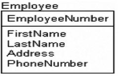
At this point, you would simply enter all of the attributes that you discover from the requirements (the next chapter will demonstrate this process). As I will demonstrate in Chapter 5, the attributes will be transformed a great deal during the normalization process, but the process is iterative, and the goal will be to capture the details that are discovered. For example, the attributes of an Employee entity may start out as follows:

However, during the normalization process, tables like this will often be broken down into many attributes (e.g., address might be broken into number, street name, city, state, zip code, etc.) and possibly different entities depending on your actual system’s needs.
![]() Note Attribute naming is one place where I tend to deviate slightly from IDEF1X. The standard is that names are unique within a model, not just within a table. This tends to produce names that include the table name (or worse yet some table name prefix) followed by the attribute name, which can result in unwieldy, long names that look archaic.
Note Attribute naming is one place where I tend to deviate slightly from IDEF1X. The standard is that names are unique within a model, not just within a table. This tends to produce names that include the table name (or worse yet some table name prefix) followed by the attribute name, which can result in unwieldy, long names that look archaic.
Just as with entity names, there is no need to include Hungarian notation prefixes or suffixes in names to let you know it is a column. However, there is value in structuring names in a very straightforward way to let the reader know what the column means. The implementation details of the attribute can be retrieved from the system catalog if there is any question about it.
The format I use is loosely based on the concepts in ISO 11179, though there really is not much freely available about this standard available in a format that is worth referencing. Generally, the idea is that names include standard parts that are put together to form a standard-looking name. I will use the following parts in my names:
- RoleName: Optionally explains a specific role the attribute plays.
- Attribute: The primary purpose of the attribute being named. Optionally can be omitted, meaning it refers directly to the entity.
- Classword: A required term that identifies the primary usage of the column, in non-implementation-specific terms. Examples: Name, Code, Amount
- Scale: Optional to tell the user what the scale of the data is, like minutes, seconds, dollars, euros, etc.
Here are some examples of attribute names using some or all of the standard parts:
- Name: Simply uses a classword to denote a textual string that names the row value, but whether or not it is a varchar(30) or nvarchar(128) is immaterial (Without a role name, the name should apply directly to an instance of the entity. Example: Company.Name is the name of the company itself.)
- UserName: An attribute and a classword, where the attribute tells the more specific use of the Name classword to indicate what type of name. (Example: Company.UserName would be the username the company uses. More context would be acquired from the name and purpose of the database.)
- AdminstratorUserName: A rolename added to the UserName attribute, identifying the specific role the user plays that is being named.
- PledgeAmount: Here the attribute Pledge is coupled with the money class, which is an amount of money, no matter the datatype which is used.
- PledgeAmountEuros: Indicates that for the PledgeAmount, this is an amount of money pledged, but with an atypical scale for the context of the database.
- FirstPledgeAmountEuros: Plays the role of the first PledgeAmount recorded in euros, unlike the previous which could be any pledge in order.
- StockTickerCode: Couples the Code classword (a short textual string) with the attribute part: StockTicker. So this is a short textual string representing a stock ticker. Note that each part of the name need not be a single word.
- EndDate: The Date classword says that this will not include a time part, and the attribute is the ending date for the row.
- SaveTime: Much like the previous attribute, only now it is a time, which will be treated as a point in time.
Almost all of the names used throughout the book will be in this format, unless I am explicitly attempting to demonstrate alternative naming. One of the most important parts of your database design is going to be consistent naming to assist users in understanding what you have built.
Next, we will go over the following aspects of attributes on your data model:
- Primary keys
- Alternate keys
- Foreign keys
- Domains
- Attribute naming
Primary Keys
As noted in the previous section, an IDEF1X entity must have a primary key. This is convenient for us, because an entity is defined such that each instance must be unique (see Chapter 1). The primary key may be a single attribute, or it may be a composite of multiple attributes. A value is required for every attribute in the key (logically speaking, no NULLs are allowed in the primary key).
The primary key is denoted by placing attributes above a horizontal line through the entity rectangle, as shown next. Note that no additional notation is required to indicate that the value is the primary key.

For example, consider the Employee entity from the previous section. The EmployeeNumber attribute is unique, and logically, every employee would have one, so this would be an acceptable primary key:
The choice of primary key is an interesting one. In the early logical modeling phase, I generally do not like to spend time choosing the final primary key attribute(s). I tend to create a simple surrogate primary key to migrate to other entities to help me see when there is any ownership. In the current example, EmployeeNumber clearly refers to an employee, but not every entity will be so clear—not to mention that more advanced business rules may dictate that EmployeeNumber is not always unique. (For example, the company also may have contractors in the table that have the same EmployeeNumber value, thus requiring EmployeeType as part of the key. That’s not a good practice perhaps, but no matter how much I try to describe perfect databases in this book, the business world is full of weird, archaic practices that you will have to incorporate into your models.) Having to go back repeatedly and change the attribute used for the primary key in the logical model can be tiresome, particularly when you have a very large model.
It is also quite likely that you may have multiple column sets that uniquely identify a given instance of many of your entities. As an example, consider an entity that models a product manufactured by a company. The company may identify the product by the type, style, size, and series:

The name may also be a good key, and more than likely, there is also a product code. Which attribute is the best key—or which is even truly a key—may not become completely apparent until later in the process. There are many ways to implement a good key, and the best way may not be recognizable right away.
Instead of choosing a primary key at this point, I add a value to the entity for identification purposes and then model all candidate keys as alternate keys (which I will discuss in the next section). As a result, the logical model clearly shows what entities are in an ownership role to other entities, since the key that is migrated contains the name of the modeled entity. I would model this entity as follows:

![]() Note Using surrogate keys is certainly not a requirement in logical modeling; it is a personal preference that I have found a useful documentation method to keep models clean, and it corresponds to my method of implementation later. Not only is using a natural key as the primary key in the logical modeling phase reasonable but many architects find it preferable. Either method is perfectly acceptable (and just as likely to start a philosophical debate at a table of data modelers—you have been warned, so start the debate after the dessert course).
Note Using surrogate keys is certainly not a requirement in logical modeling; it is a personal preference that I have found a useful documentation method to keep models clean, and it corresponds to my method of implementation later. Not only is using a natural key as the primary key in the logical modeling phase reasonable but many architects find it preferable. Either method is perfectly acceptable (and just as likely to start a philosophical debate at a table of data modelers—you have been warned, so start the debate after the dessert course).
Alternate Keys
As defined in Chapter 1, an alternate key is a grouping of one or more attributes whose uniqueness needs to be guaranteed over all of the instances of the entity. Alternate keys do not have specific locations in the entity graphic like primary keys, nor are they typically migrated for any relationship (you can reference an alternate key with a foreign key based on the SQL standards, but this feature is very rarely used, and when used, it often really confuses even the best DBAs). They are identified in the model in a very simple manner:

In this example, there are two alternate key groups: group AK1, which has one attribute as a member, and group AK2, which has two attributes. There also is nothing wrong with overlapping alternate keys, which could be denoted as (AK1,AK2). Thinking back to the product example, the two keys could then be modeled as follows:

One extension that the ERwin data modeling tool adds to this notation is shown here:

A position number notation is tacked onto the name of each key (AK1 and AK2) to denote the position of the attribute in the key. In the logical model, technically, the order of attributes in the key should not be considered even if the tool does display them (unique is unique, regardless of key column order). Which attribute comes first in the key really does not matter; all that matters is that you make sure there are unique values across multiple attributes. When a key is implemented in the database, the order of columns will almost certainly become interesting for performance reasons, but uniqueness will be served no matter what the order of the columns of the key is.
![]() Note Primary and unique constraints are implemented with indexes in SQL Server, but the discussion of index utilization for performance reasons is left to Chapter 10. Do your best to more or less ignore performance tuning needs during the conceptual, logical design phases. Defer most performance tuning issues until you are coding and have enough data to really see what indexes are needed.
Note Primary and unique constraints are implemented with indexes in SQL Server, but the discussion of index utilization for performance reasons is left to Chapter 10. Do your best to more or less ignore performance tuning needs during the conceptual, logical design phases. Defer most performance tuning issues until you are coding and have enough data to really see what indexes are needed.
Foreign Keys
Foreign key attributes, as mentioned, are also referred to as migrated attributes. They are primary keys from one entity that serve as references to an instance in another entity. They are, again, a result of relationships (we’ll look at their graphical representation later in this chapter). They are indicated, much like alternate keys, by adding the letters “FK” after the foreign key:

As an example of a table with foreign keys, consider an entity that is modeling a music album:

The ArtistId and PublisherId represent migrated foreign keys from the Artist and Publisher entities. We’ll revisit this example in the “Relationships” section later in this chapter.
One tricky thing about foreign keys is that the diagram doesn’t show what entity the key is migrated from. This can tend to make things a little messy, depending on how you choose your primary keys. This lack of clarity about what table a foreign key migrates from is a limitation of most modeling methodologies, because displaying the name of the entity where the key came (though some tools have this option available) from would be unnecessarily confusing for a couple of reasons:
- There is no limit (nor should there be) on how far a key will migrate from its original owner entity (the entity where the key value was not a migrated foreign key reference).
- It is not completely unreasonable that the same attribute might migrate from two separate entities with the same name, especially early in the logical design process. This is certainly not a best practice at all, but it is possible and can make for interesting situations.
As you can see, one of the reasons for the primary key scheme I will employ in logical models is to add a key named <entityName>Id as the identifier for entities, so the name of the entity is easily identifiable and lets us easily know where the original source of the attribute is. Also, we can see the attribute migrated from entity to entity even without any additional documentation. For example, in the Album entity example, we instinctively know that the ArtistId attribute is a foreign key and most likely was migrated from the Artist entity just because of the name alone.
Domains
In Chapter 1, the term “domain” referred to a set of valid values for an attribute. In IDEF1X, you can formalize domains and define named, reusable specifications known as domains, for example:
- String: A character string
- SocialSecurityNumber: A character value with a format of ###-##-####
- PositiveInteger: An integer value with an implied domain of 0 to max(integer value)
- TextualFlag: A five-character value with a domain of (’FALSE’,’TRUE’)
Domains in the specification not only allow us to define the valid values that can be stored in an attribute but also provide a form of inheritance in the datatype definitions. Subclasses can then be defined of the domains that inherit the settings from the base domain. It is a good practice to build domains for any attributes that get used regularly, as well as domains that are base templates for infrequently used attributes. For example, you might have a character type domain where you specify a basic length, like 60. Then, you may specify common domains, like name and description, to use in many entities. For these, you should choose a reasonable length for the values, plus you could include a requirement that the data in the column cannot be just space characters, to prevent a user from having one, two, or three spaces each look like different values—except in the rare cases where that is desirable.
Regardless of whether or not you are using an automated tool for modeling, try to define common domains that you use for specific types of things. For example, a person’s first name might be a domain. This is cool because you don’t have to answer more than once questions such as “Hmm, how long to make a person’s name?” or “What is the format of our part numbers?” After you make a decision, you just use what you have used before.
If it sounds unreasonable that you might argue about a datatype length, it is likely that you haven’t been employed at a job without a nametag just yet. Programmers argue all of the time, but if you establish a standard after the first argument, you only have to have that argument once. Note too that most everything you want to store data on has been done before, so look to standards documents on the Web. For example, how long might a dialable phone number column be? The answer is 15 characters based on ITU-T E.164 (http://searchnetworking.techtarget.com/definition/E164). So making it 100 characters “just in case one day it is 6.66 times longer” is silly, not to mention bad for data integrity.
![]() Note Defining common domains during design fights against another major terrible practice, the string(200) syndrome (or similar string length), where every column in a database stores textual data in columns of exactly same length. Putting in some early thought on the minimum and maximum lengths of data is easier than doing it when the project manager is screaming for results later in the process, and the programmers are champing at the bit to get at your database and get coding. It is also the first step in producing databases with data integrity.
Note Defining common domains during design fights against another major terrible practice, the string(200) syndrome (or similar string length), where every column in a database stores textual data in columns of exactly same length. Putting in some early thought on the minimum and maximum lengths of data is easier than doing it when the project manager is screaming for results later in the process, and the programmers are champing at the bit to get at your database and get coding. It is also the first step in producing databases with data integrity.
Early in the modeling process, you’ll commonly want to gather a few bits of information, such as the general type of the attribute: character, numeric, logical, or even binary data. Determining minimum and maximum lengths may or may not be possible, but the more information you can gather without crushing the process the better. Another good thing to start is documenting the legal values for an attribute that is classified as being of the domain type. This is generally done using some pseudocode or in a textual manner, either in your modeling tool or even in a spreadsheet.
It is extremely important to keep these domains as implementation-independent datatype descriptions. For example, you might specify a domain of GloballyUniqueIdentifier, a value that will be unique no matter where it is generated. In SQL Server, a unique identifier could be used (GUID value) to implement this domain. In another database system (created by a company other than Microsoft, perhaps) where there is not exactly the same mechanism, it might be implemented differently; the point is that this value is statistically guaranteed to be unique every time it is generated. The conceptual/logical modeling phase should be done without too much thinking about what SQL Server can do, if for no other reason than to prevent you from starting to impose limitations on the future solution prior to understanding the actual problem. Another sort of domain might be a set of legal values, like if the business users had defined three customer types, you could specify the legal string values that could be used.
When you start the physical modeling of the physical relational structures, you will use the same domains to assign the implementation properties. This is the real value in using domains. By creating reusable template attributes that will also be used when you start creating columns, you’ll spend less effort and time building simple entities, which makes up a lot of your work. Doing so also provides a way for you to enforce companywide standards, by reusing the same domains on all corporate models (predicated, of course, on your being diligent with your data modeling processes over time!).
Later on, implementation details such as exact datatypes, constraints, and so forth will be chosen, just to name a few of the more basic properties that may be inherited (and if Microsoft adds a more suitable datatype for a situation in the future, you can simply—at least from the model’s standpoint—change all of the columns with that domain type to the new type). Since it is very likely that you will have fewer domains than implemented attributes, the double benefit of speedy and consistent model assembly is achieved. However, it is probably not overly reasonable or even useful to employ the inheritance mechanisms when building tables by hand. Implementation of a flat domain structure is enough work without a tool.
As an example of a domain hierarchy, consider this set of character string domains:

Here, String is the base domain from which you can then inherit Name and Description. FileName, FirstName, and LastName are inherited from Name. During logical modeling, this might seem like a lot of work for nothing, because most of these domains will share only a few basic details, such as not allowing NULLs or blank data. However, FileName may be optional, whereas LastName might be mandatory. Setting up domains for as many distinct attribute types as possible is important, in case rules or datatypes are discovered that are common to any domains that already exist. Things get good when you need to change all of your datatypes for all string types, for example, if you decide to finally make that blanket change from ANSI character sets to UNICODE, or to implement encryption on all personal notes–type attributes but not name ones.
During logical modeling, domains might optionally be shown to the right of the attribute name in the entity (which is where you will eventually see the SQL Server datatype as well):

So if I have an entity that holds domain values for describing a type of person, I might model it as follows:

To model this example, I defined four domains:
- SurrogateKey: The surrogate key value. (Implementation of the surrogate should not be implied by building a domain, so later, this can be implemented in any manner.)
- Description: Holds the description of “something” (can be 60 characters maximum).
- PersonFirstName: A person’s first name (30 characters maximum).
- PersonLastName: A person’s last name (50 characters maximum).
The choice of the length of name is an interesting one. I searched on Bing for “person first name varchar” and found lots of different possibilities: 10, 35, unlimited, 25, 20, and 15—all on the first page of the search! Just as you should use a consistent naming standard, you should use standard lengths every time that like data is represented, so when you hit implementation, the likelihood that two columns storing like data will have different definitions is minimized.
During the implementation phase, all of the domains will get mapped to some form of datatype in SQL Server. However, the future implementation isn’t quite the point at this point of the process. The point of a domain in the logical model is to define common types of storage patterns that can be applied in a common manner, including all of the business rules that will govern their usage.
If you follow the naming standard I discussed earlier made up of RoleName + Attribute + Classword + Scale, you may find that your domains often share a lot of similarity with that hierarchy. Name is a classword, and Name is in our domain list. FirstName is an attribute and classword that also ends up as a domain. Domains, however, will often include things like size. Name30Characters, Name60Characters, etc. may not be good classwords, but they can be perfectly acceptable domains in some cases where you just want a class of names that are 30 characters, and don’t want to make one domain per attribute. Domains are there for your sake, to make things easier for you, so do what makes more sense.
Relationships
Up to this point, the visual constructs we have looked at have been pretty much the same across most data modeling methodologies. Entities are almost always signified by rectangles, and attributes are quite often words within the rectangles. Relationships are where things start to diverge greatly, as many of the different modeling languages approach representing relationships graphically a bit differently. To make the concept of relationships clear, I need to go back to the terms “parent” and “child.” Consider the following definitions from the IDEF1X specification’s glossary (as these are remarkably lucid definitions to have been taken straight from a government specification!):
- Entity, Child: The entity in a specific connection relationship whose instances can be related to zero or one instance of the other entity (parent entity)
- Entity, Parent: An entity in a specific connection relationship whose instances can be related to a number of instances of another entity (child entity)
- Relationship: An association between two entities or between instances of the same entity
In IDEF1X, every relationship is denoted by a line drawn between two entities, with a solid circle at one end of that line to indicate where the primary key attribute is migrated to as a foreign key. In the following image, the primary key of the parent will be migrated to the child.

Relationships come in several different flavors that indicate how the parent table is related to the child. We will look at examples of several different relationship concepts in this section:
- Identifying, where the primary key of one table is migrated to the primary key of another. The child will be a dependent entity.
- Nonidentifying, where the primary key of one table is migrated to the nonprimary key attributes of another. The child will be an independent entity as long as no identifying relationships exist.
- Optional nonidentifying, when the nonidentifying relationship does not require a parent value.
- Recursive relationships, when a table is related to itself.
- Subtype or categorization, which is a one-to-one relationship used to let one entity extend another.
- Many-to-many, where an instance of an entity can be related to many in another, and in turn, many instances of the second entity can be related to multiples in the other.
We’ll also cover the cardinality of the relationship (how many of the parent relate to how many of the child), role names (changing the name of a key in a relationship), and verb phrases (the name of the relationship). Relationships are a key topic in a database design diagram and not a completely simple one. A lot of information is related using a few dots and lines. Often it will help to look at the metadata that is represented in the graphical display to make sure it is clear (particularly if looking at a foreign modeling language!).
![]() Note All of the relationships discussed in this section (except many-to-many) are of the one-to-many variety, which encompasses one-to-zero, one-to-one, one-to-many, or perhaps exactly-n relationships. Technically, it is more accurately one-to-(from M to N), as this enables specification of the many in very precise (or very loose) terms as the situation dictates. However, the more standard term is “one-to-many,” and I will not try to make an already confusing term more so.
Note All of the relationships discussed in this section (except many-to-many) are of the one-to-many variety, which encompasses one-to-zero, one-to-one, one-to-many, or perhaps exactly-n relationships. Technically, it is more accurately one-to-(from M to N), as this enables specification of the many in very precise (or very loose) terms as the situation dictates. However, the more standard term is “one-to-many,” and I will not try to make an already confusing term more so.
Identifying Relationships
The concept of a relationship being identifying is used to indicate containership, that the essence (defined as the intrinsic or indispensable properties that serve to characterize or identify something) of the child instance is defined by the existence of a parent. Another way to look at this is that generally the child in an identifying relationship is an inseparable part of the parent. Without the existence of the parent, the child would make no sense.
The relationship is drawn as follows:
![]()
To implement this relationship in the model, the primary key attribute(s) is migrated to the primary key of the child. Hence, the key of a parent instance is needed to be able to identify a child instance record, which is why the name “identifying relationship” is used. In the following example, you can see that the ParentId attribute is a foreign key in the Child entity, from the Parent entity.
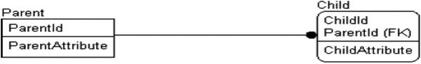
The child entity in the relationship is drawn as a rounded-off rectangle, which, as mentioned earlier in this chapter, means it is a dependent entity. A common example is an invoice and the line items being charged to the customer on the invoice:
![]()
It can also be said that the line items are part of the parent, much like in an object you might have a property that is an array, but since all values are stored as scalars in SQL, we end up with more tables instead of different datatypes.
Nonidentifying Relationships
The nonidentifying relationship indicates that the parent represents a more informational attribute of the child. When implementing the nonidentifying relationship, the primary key attribute is migrated as a non-primary key attribute of the child. It is denoted by a dashed line between the entities. Note too that the rectangle representing the child now has squared-off corners, since it stands alone, rather than being dependent on the Parent:

Now you can see that the attribute ParentID is migrated to the non-key attributes:

Taking again the example of an invoice, consider the vendor of the products that have been sold and documented as such in the line items. The product vendor does not define the existence of a line item, because with or without specifying the exact vendor the product originates from, the line item still makes sense.
The difference between identifying and nonidentifying relationships can sometimes be tricky but is essential to understanding the relationship between tables and their keys. If the parent entity defines the need for the existence of the child (as stated in the previous section), then use an identifying relationship. If, on the other hand, the relationship defines one of the child’s attributes, use a nonidentifying relationship.
Here are some examples:
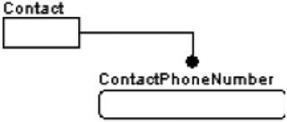
- Identifying: You have an entity that stores a contact and another that stores the contact’s telephone number. The Contact owns defines the phone number, and without the contact, there would be no need for the ContactPhoneNumber instance.
- Nonidentifying: Consider the entities that were defined for the identifying relationship, along with an additional entity called ContactPhoneNumberType. This entity is related to the ContactPhoneNumber entity, but in a nonidentifying way, and defines a set of possible phone number types (Voice, Fax, etc.) that a ContactPhoneNumber might be. The type of phone number does not identify the phone number; it simply classifies it. Even if the type wasn’t known, recording the phone number would still be interesting, as the number still may have informational merit. However, a row associating a contact with a phone number would be useless information without the contact’s existence.

The ContactPhoneNumberType entity is commonly known as a domain entity or domain table, as it serves to implement an attribute’s domain in a nonspecific manner. Rather than having a fixed domain for an attribute, an entity is designed that allows programmatic changes to the domain with no recoding of constraints or client code. As an added bonus, you can add columns to define, describe, and extend the domain values to implement business rules. It also allows the client user to build lists for users to choose values with very little programming.
While every nonidentifying relationship defines the domain of an attribute of the child table, sometimes when the row is created, the values don’t need to be selected. For example, consider a database where you model houses, like for a neighborhood. Every house would have a color, a style, and so forth. However, not every house would have an alarm company, a mortgage holder, and so on. The relationship between the alarm company and bank would be optional in this case, while the color and style relationships could be mandatory. The difference in the implemented table will be whether or not the child table’s foreign key columns will allow NULLs. If a value is required, then it is considered mandatory. If a value of the migrated key can be NULL, then it is considered optional.
The optional case is signified by an open diamond at the opposite end of the dashed line from the black circle, as shown here:

In the mandatory case, the relationship is drawn as before, without the diamond. Note that an optional relationship means that the cardinality of the relationship may be zero or greater, but a mandatory relationship must have a cardinality of one or greater (as defined in Chapter 1, cardinality refers to the number of values that can be related to another value, and the concept will be discussed further in the next section as well).
![]() Note You might be wondering why there is not an optional identifying relationship. This is because you may not have any optional attributes in a primary key, which is true in relational theory and SQL Server as well.
Note You might be wondering why there is not an optional identifying relationship. This is because you may not have any optional attributes in a primary key, which is true in relational theory and SQL Server as well.
For a one-to-many, optional relationship, consider the following:

The invoiceLineItem entity is where items are placed onto an invoice to receive payment. The user may sometimes apply a standard discount amount to the line item. The relationship, then, from the invoiceLineItem to the discountType entity is an optional one, as no discount may have been applied to the line item.
For most optional relationships like this, there is another possible solution, which can be modeled as required, and in the implementation, a row can be added to the discountType table that indicates “none” or “unknown.” An example of such a mandatory relationship could be genre to movie in a movie rental system database:

The relationship is genre <classifies> movie, where the genre entity represents the “one” and movie represents the “many” in the one-to-many relationship. Every movie being rented must have a genre, so that it can be organized in the inventory and then placed on the appropriate rental shelf. If the movie is new, but the genre wasn’t yet known, a row in the genre object with a genre of “New” or “Unknown” could be used. Whether or not to use an optional relationship, or to manufacture a row that means the lack of a value, is discussed quite frequently. Generally, it is frowned upon in nonreporting databases to come up with a value that means “There is not a real related value” because it can cause confusion. Users who are writing a query and end up seeing sales to a “Missing Customer” might not be sure if that is the name of a funky new restaurant or a manufactured row. In reporting you generally are just looking at groupings, so it is less of an issue and you will design some way to make the row sort to the top or the bottom of the list.
Role Names
A role name is an alternative name you can give an attribute when it is used as a foreign key. The purpose of a role name is to clarify the usage of a migrated key, because either the parent entity is generic and a more specific name is needed or the same entity has multiple relationships to the same entity. As attribute names must be unique, assigning different names for the child foreign key references is often necessary. Consider these tables:

In this diagram, the Parent and Child entities share two relationships, and the migrated attributes have been role named as FirstParentPrimaryKey and SecondParentPrimaryKey. In diagrams, you can indicate the original name of the migrated attribute after the role name, separated by a period (.), as follows (but usually it takes up too much space on the model):

As an example, say you have a User entity, and you want to store the name or ID of the user who created a DatabaseObject entity instance as well as the user that the DatabaseObject instance was created for. It would then end up as follows:
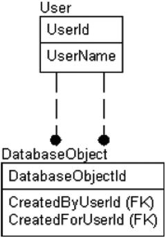
Note that there are two relationships to the DatabaseObject entity from the User entity. Due to the way the lines are drawn on a diagram, it is not clear from the diagram which foreign key goes to which relationship. Once you name the relationship (with a verb phrase, which will be covered later in this chapter), the key’s relationships will be easier to determine, but often, determining which line indicates which child attribute is simply trial and error.
Relationship Cardinality
The cardinality of the relationship is the number of child instances that can be inserted for each parent instance of that relationship. A lot of people slough off this topic in requirements and design because it can be difficult to implement. However, our initial goal is to represent the requirements in our data models, and leave discussion of data constraint implementation to later (we will start discussing implementation in Chapter 6 when we implement our first database, and discuss it even more in Chapter 7, the data protection chapter, and throughout the latter half of the book).
Figures 3-1 through 3-6 show the six possible cardinalities that relationships can take. The cardinality indicators are applicable to either mandatory or optional relationships.

Figure 3-1. One-to-zero or more

Figure 3-2. One-to-one or more (at least one), indicated by P

Figure 3-3. One-to-zero or one (no more than one), indicated by Z

Figure 3-4. One-to-some fixed range (in this case, between 4 and 8 inclusive)

Figure 3-5. One-to-exactly N (in this case, 5, meaning each parent must have five children)

Figure 3-6. Specialized note describing the cardinality
For example, a possible use for the one-to-one or more (see Figure 3-2) might be to represent the relationship between a guardian and a student in an elementary school:
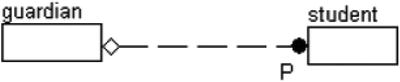
This is a good example of a zero-or-one to one-or-more relationship, and a fairly interesting one at that. It says that for a guardian instance to exist, a related student must exist, but a student need not have a guardian for us to wish to store the student’s data.
Next, let’s consider the case of a club that has members with certain positions that they should or could fill, as shown in Figures 3-7 through 3-9.
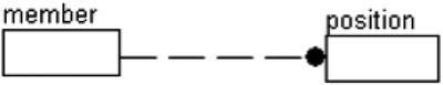
Figure 3-7. One-to-many allows unlimited positions for the member

Figure 3-8. One-to-one allows only one position per member

Figure 3-9. A one-to-zero, one-to-one, or one-to-two relationship specifies a limit of two positions per member
Figure 3-7 shows that a member can take as many positions as are possible. Figure 3-8 shows that a member can serve in no position or one position, but no more. Finally, Figure 3-9 shows that a member can serve in zero, one, or two positions. They all look very similar, but the Z or 0–2 is important in signifying the cardinality.
![]() Note It is not an overly common occurrence that I have needed anything other than the basic one-to-many, one-to-zero-or-one relationship types, but your experience may lend itself to the specialized relationship cardinalities.
Note It is not an overly common occurrence that I have needed anything other than the basic one-to-many, one-to-zero-or-one relationship types, but your experience may lend itself to the specialized relationship cardinalities.
Recursive Relationships
One of the more difficult—and often important—relationship types to implement is the recursive relationship, also known as a self-join, hierarchical, self-referencing, or self-relationship (I have even heard them referred to as fish-hook relationships, but that name always seems silly to me). It is used to model some form of hierarchy, where one row is related to one and only one parent. The “recursive” part of the name references the method of traversing the structure. In Chapter 8 we will look in more depth at hierarchies, some that use a recursive relationship, some that do not.
The recursive relationship is modeled by drawing a nonidentifying relationship not to a different entity, but to the same entity. The migrated key of the relationship is given a role name. (In many cases, a naming convention of adding “parent” or “referenced” to the front of the attribute name is useful if no natural naming is available.)

The recursive relationship is useful for creating tree structures, as in the following organizational chart:
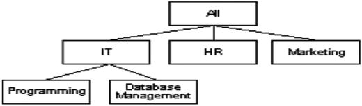
To explain this concept fully, I will show the data that would be stored to implement this hierarchy:

Here is the sample data for this table:
OrganizationName      ParentOrganizationName
--------------------  ----------------------
All
IT                    ALL
HR                    ALL
Marketing             ALL
Programming           IT
Database Management   IT
The organizational chart can now be traversed by starting at All and getting the children of ALL, for example: IT. Then, you get the children of those values, like for IT one of the values is Programming.
As a final example, consider the case of a Person entity. If you wanted to associate a person with a single other person as the first person’s current spouse, you might design the following:
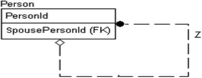
Notice that this is a one-to-zero-or-one relationship, since (in most places) a person may have no more than a single spouse but need not have one. If you require one person to be related as a child to two parents, another table entity is required to link two people together. Note that I said “current” spouse earlier in the section. If you need to know history of changes in hierarchy, you will need some of the more complex versions of modeling hierarchies that we will cover in some detail in Chapter 8 when we discuss various modeling patterns and techniques. In this chapter, it is strictly important that you can grasp what the hierarchical relationship looks like on a data model.
Subtypes
Subtypes (also referred to as categorization relationships) are a special type of one-to-zero-or-one relationship used to indicate whether one entity is a specific type of a generic entity. It is similar to the concept of inheritance in object-oriented programming (if a lot clunkier to work with). Note in the following diagram that there are no black dots at either end of the lines; the specific entities are drawn with rounded corners, signifying that they are, indeed, dependent on the generic entity.

There are three distinct parts of the subtype relationship:
- Generic entity: This entity contains all of the attributes common to all of the subtyped entities.
- Discriminator: This attribute acts as a switch to determine the entity where the additional, more specific information is stored.
- Specific entity: This is the place where the specific information is stored, based on the discriminator.
For example, consider an inventory of your home video library. If you wanted to store information about each of the videos that you owned, regardless of format, you might build a categorization relationship like the following:

In this manner, you might represent each video’s price, title, actors, length, and possibly description of the content in the VideoProgram entity, and then, based on format—which is the discriminator—you might store the information that is specific to Disc or FileSystem in its own separate entity (e.g., physical location, special features, format [BluRay, DVD, digital copy] for Disc-based video, and directory and format for FileSystem).
There are two distinct category types: complete and incomplete. The complete set of categories is modeled with a double line on the discriminator, and the incomplete set is modeled with a single line (see Figure 3-10).

Figure 3-10. Complete (left) and incomplete (right) sets of categories
The primary difference between the complete and incomplete categories is that in the complete categorization relationship, each generic instance must have one specific instance, whereas in the incomplete case, this is not necessarily true. An instance of the generic entity can be associated with an instance of only one of the category entities in the cluster, and each instance of a category entity is associated with exactly one instance of the generic entity. In other words, overlapping subentities are not allowed.
For example, you might have a complete set of categories like this:
This relationship indicates that “An Animal must be either a Dog or a Cat.” (Clearly true only in the context of the requirements for this company, naturally. However, what it doesn’t show us is first, do we have to know that the animal type is known? There may be no rows in Dog or Cat at all, and animal type may be NULL.
However, what if this were modeled as an incomplete set of categories:
Now in our database, we may have Dog, Cat, Fish, Lizard, etc., but we only have specific information recorded for Dog and Cat.
Additionally, a concept that is mentioned occasionally is whether a subclass is exclusive or not exclusive. For the animal, Animal can clearly only be a Dog, Cat, etc., not both. But consider the common subclass of Person to Customer, Employee, and Manager. A person can be a manager, who is also an employee, and it may be advantageous to track their customer relationship in the same database from the subclass structure. This would not be an exclusive subtype.
The many-to-many relationship is also known as the nonspecific relationship, which is actually a better name, but far less well known. Having lots of many-to-many relationships in the data model is common, though they will be modeled as something different when you are building your physical model. These relationships are modeled by a line with a solid black dot on both ends:

There is one real problem with modeling a many-to-many relationship, even in the logical model: it is often necessary to have more information about the relationship than that simply many EntityX instances are connected to many EntityY instances. So, much like any many-to-many relationship will be implemented, the relationship is usually modeled as follows very soon after its discovery:

Here, the intermediate EntityX_EntityY entity is known as an associative entity (names like bridge, tweener, and joiner are not uncommon either). In early modeling, I will often stick with the former representation when I haven’t identified any extended attributes to describe the relationship and the latter representation when I need to add additional information to the model. To clarify the concept, let’s look at the following example:

Here, I have set up a relationship where many customers are related to many products. This situation is common because in most cases, companies don’t create specific products for specific customers; rather, any customer can purchase any of the company’s products, or certainly a subset of products that are also orderable by other customers. At this point in the modeling, it is likely reasonable to use the many-to-many representation. Note that I am generalizing the customer-to-product relationship. It is not uncommon to have a company build specific products for only one customer to purchase, making for a more interesting modeling requirement.
Consider, however, the case where the Customer need only be related to a Product for a certain period of time. To implement this, you can use the following representation:

In fact, almost all of the many-to-many relationships tend to require some additional information like this to make them complete. It is not uncommon to have no many-to-many relationships modeled with the black circle on both ends in anything other than a simple conceptual model, so you will need to look for entities modeled like this to be able to discern them.
![]() Note You can’t implement a many-to-many relationship in SQL without using a table for the resolution because there is no way to migrate keys both ways. In the database, you are required to implement all many-to-many relationships using an associative table.
Note You can’t implement a many-to-many relationship in SQL without using a table for the resolution because there is no way to migrate keys both ways. In the database, you are required to implement all many-to-many relationships using an associative table.
Verb Phrases (Relationship Names)
Relationships are given names, called verb phrases, to make the relationship between a parent and child entity a readable sentence and to incorporate the entity names and the relationship cardinality. The name is usually expressed from parent to child, but it can be expressed in the other direction, or even in both directions. The verb phrase is located on the model somewhere close to the line that forms the relationship:

The relationship should be named such that it fits into the following general structure for reading the entire relationship: parent cardinality - parent entity name - relationship name - child cardinality - child entity name.
For example, consider the following relationship:

It would be read as “one Contact is phoned using zero, one, or more PhoneNumbers.”
Of course, the sentence may or may not make perfect sense in normal conversational language; for example, this one brings up the question of how a contact is phoned using zero phone numbers. If presenting this phrase to a nontechnical person, it would make more sense to read it as follows: “Each contact can have either no phone number or one or more phone numbers,” or perhaps “If the contact has a phone number, the contact can be phoned with one or more phone numbers.” You don’t want to simply use “have” for all verb phrases, as the goal of the verb phrase is to capture the essence of how the data will be used and provide documentation that doesn’t need editing to be semantically understandable (even if not tremendously impressive prose).
Being able to read the relationship helps you to notice obvious problems. For instance, consider the following relationship:

It looks fine at first glance, but when read as “one ContactType classifies zero or one Contacts,” it doesn’t make logical sense (since Contact requires a ContactType, you would need the same number or more rows in a ContactType table). This would be properly modeled as follows:

which now reads, “one ContactType classifies zero or more Contacts.”
Note that the type of relationship, whether it is identifying, nonidentifying, optional, or mandatory, makes no difference when reading the relationship. You can also include a verb phrase that reads from child to parent. For a one-to-many relationship, this would be of the following format: “One child instance (relationship) exactly one parent instance.”
In the case of the first example, you could have added an additional verb phrase:

The parent-to-child relationship again is read as “one Contact is phoned using zero, one, or more phoneNumbers.”
You can then read the relationship from child to parent. Note that, when reading in this direction, you are in the context of zero or one phone number to one and only one contact: “zero or one phoneNumbers may be used to phone exactly one contact.”
Since this relationship is going from many to one, the parent in the relationship is assumed to have one related value, and since you are reading in the context of the existence of the child, you can also assume that there is zero or one child record to consider in the sentence.
For the many-to-many relationship, the scheme is pretty much the same. As both entities are parents in this kind of relationship, you read the verb phrase written above the line from left to right, and read the verb phrase written below the line from right to left.

![]() Note Taking the time to define verb phrases can be a hard sell, because they are not actually used in a substantive way in the implementation of the database, and often people consider doing work that doesn’t produce code directly to be a waste of time. However, well-defined verb phrases make for great documentation, giving the reader a good idea of why the relationship exists and what it means. I usually use the verb phrase when naming the foreign key constraints too, which you will see in Chapter 6 when we actually create a database with foreign keys.
Note Taking the time to define verb phrases can be a hard sell, because they are not actually used in a substantive way in the implementation of the database, and often people consider doing work that doesn’t produce code directly to be a waste of time. However, well-defined verb phrases make for great documentation, giving the reader a good idea of why the relationship exists and what it means. I usually use the verb phrase when naming the foreign key constraints too, which you will see in Chapter 6 when we actually create a database with foreign keys.
Descriptive Information
Take a picture of a beautiful mountain, and it will inspire thousands of words about the beauty of the trees, the plants, the babbling brook (my ability to describe a landscape being one of the reasons I write technical books). What it won’t tell you is how to get there yourself, what the temperature is, and whether you should bring a sweater and mittens or your swim trunks.
Data models are the same way. So far we have only really discussed things you can see in the graphical part of the model. You can get a great start on understanding the database from the picture, as I have discussed in the previous sections of this chapter. We started the documentation process by giving good names to entities, attributes, and the relationships, but even with well-formed names, there will still likely be confusion as to what exactly an attribute is used for and how it might be used.
For this, we need to add our own thousand words (give or take) to the pictures in the model. When sharing the model, descriptions will let the eventual reader—and even a future version of yourself—know what you originally had in mind. Remember that not everyone who views the models will be on the same technical level: some will be nonrelational programmers, or indeed users or (nontechnical) product managers who have no modeling experience.
Descriptive information need not be in any special format. It simply needs to be detailed, up to date, and capable of answering as many questions as can be anticipated. Each bit of descriptive information should be stored in a manner that makes it easy for users to quickly connect it to the part of the model where it was used, and it should be stored either as metadata in a modeling tool (preferably) or in some sort of document that will be easy to maintain in the future.
You should start creating this descriptive text by asking questions such as the following:
- What is the object supposed to represent?
- How will the object be used?
- Who might use the object?
- What are the future plans for the object?
- What constraints are not specifically implied by the model?
The scope of the descriptions should not extend past the object or entities that are affected. For example, the entity description should refer only to the entity, and not any related entities, relationships, or even attributes unless completely necessary. An attribute definition should only speak to the single attribute and where its values might come from. It is also a good idea to avoid a lot of examples, as they may change, while the model itself may not need to change.
Maintaining good descriptive information is roughly equivalent to putting decent comments in code. As the eventual database that you are modeling is usually the central part of any computer system, comments at this level are more important than at any others. For most people, being able to go back and review notes that were taken about each object and why things were implemented is invaluable, which is especially true for organizations that hire new employees and need to bring them up to speed on complex systems.
For example, say the following two entities have been modeled:

The very basic set of descriptive information in Tables 3-1 and 3-2 could be stored to describe the attributes created.
Table 3-1. Entities
|
Entity |
Attribute |
Description |
|---|---|---|
|
Contact |
Persons that can be contacted to do business with | |
|
ContactId |
Surrogate key representing a Contact | |
|
ContactTypeId |
Primary key reference for a ContactType, classifies the type of contact | |
|
Name |
The full name of a contact | |
|
ContactType |
Domain of different contact types | |
|
ContactTypeId |
Surrogate key representing a ContactType | |
|
Name |
The name that the contact type will be uniquely known as | |
|
Description |
The description of exactly how the contact should be used |
Table 3-2. Relationships

Alternative Modeling Methodologies
In this section, I will briefly describe a few of the other modeling methodologies that you will likely run into with tools you may use when looking for database information on the Web. You will see a lot of similarities among them—for example, most every methodology uses a rectangle to represent a table and a line to indicate a relationship. You will also see some big differences among them, such as how the cardinality and direction of a relationship is indicated. Where IDEF1X uses a filled circle on the child end and an optional diamond on the other, one of the most popular methodologies uses multiple lines on one end and several dashes to indicate the same things. Still others use an arrow to point from the child to the parent to indicate where the migrated key comes from (that one really confuses people who are used to IDEF1X and crow’s feet).
While all of the examples in this book will be done in IDEF1X, knowing about the other methodologies may be helpful when you are surfing around the Internet, looking for sample diagrams to help you design the database you are working on. (Architects are often particularly bad about not looking for existing designs, because frankly, solving the problem at hand is one of the best parts of the job.)
I will briefly discuss the following:
- Information engineering (IE): The other main methodology, which is commonly referred to as the crow’s feet method
- Chen Entity Relationship Model (ERD): The methodology used mostly by academics, though you can run into these models online
![]() Note This list is by no means exhaustive. For example, several variations loosely based on the Unified Modeling Language (UML) class modeling methodology are not listed. These types of diagrams are common, particularly with people who use the other components of UML, but these models really have no standards. Some further reading on UML data models can be found in Clare Churcher’s book Beginning Database Design (Apress, 2007), on Scott Adler’s AgileData site (www.agiledata.org/essays/umlDataModelingProfile.html), and on IBM’s Rational UML documentation site (www.ibm.com/software/rational), among many others. (The typical caveat that these URLs are apt to change applies.) SQL Server Management Studio includes some rudimentary modeling capabilities that can show you the model of a physical database as well.
Note This list is by no means exhaustive. For example, several variations loosely based on the Unified Modeling Language (UML) class modeling methodology are not listed. These types of diagrams are common, particularly with people who use the other components of UML, but these models really have no standards. Some further reading on UML data models can be found in Clare Churcher’s book Beginning Database Design (Apress, 2007), on Scott Adler’s AgileData site (www.agiledata.org/essays/umlDataModelingProfile.html), and on IBM’s Rational UML documentation site (www.ibm.com/software/rational), among many others. (The typical caveat that these URLs are apt to change applies.) SQL Server Management Studio includes some rudimentary modeling capabilities that can show you the model of a physical database as well.
Information Engineering
The information engineering (IE) methodology is well known and widely used (it would be a tossup as to which methodology is most common, IE or IDEF1X). Like IDEF1X, it does a very good job of displaying the necessary information in a clean, compact manner that is easy to follow. The biggest difference is in how this method denotes relationship cardinalities: it uses a crow’s foot instead of a dot and lines and uses dashes instead of diamonds and some letters.
Tables in this method are denoted as rectangles, basically the same as in IDEF1X. According to the IE standard, attributes are not shown on the model, but most models show them the same as in IDEF1X—as a list, although the primary key is often denoted by underlining the attributes, rather than the position in the table. (I have seen other ways of denoting the primary key, as well as alternate/foreign keys, but they are all typically clear.) Where things get very different using IE is when dealing with relationships.
Just like in IDEF1X, IE has a set of symbols that have to be understood to indicate the cardinality and ownership of the data in the relationships. By varying the basic symbols at the end of the line, you can arrive at all of the various possibilities for relationships. Table 3-3 shows the different symbols that can be employed to build relationship representations.
Table 3-3. Information Engineering Symbols
|
Symbol |
Relationship Type |
|---|---|
|
|
Zero, One, Or Many |
|
|
Zero Or One |
|
|
At least one or many |
|
|
One and Only One |
Figures 3-11 through 3-14 show some examples of relationships in IE.

Figure 3-11. One-to-at least one or many: Specifically, one row in Table A must be related to one or more rows in Table B. A related row must exist in Table A for a row to exist in Table B

Figure 3-12. One-to-zero, one or many: Specifically, one row in Table A may be related to one or more rows in Table B

Figure 3-13. One-to-one: Specifically, zero or one row in Table A can be related to zero or one row in Table B. A row needn’t exist in Table A for a row to exist in Table B (the key value would be optional)

Figure 3-14. Many-to-many relationship
IE conveys the information well, though, and is likely to be used in some of the documents that you will come across in your work as a data architect or developer. IE is also not always fully implemented in tools; however, usually the circles, dashes, and crow’s feet are implemented properly.
![]() Note You can find more details about the Information Engineering methodology in the book Information Engineering, Books 1, 2, and 3 by James Martin (Prentice Hall, 1990).
Note You can find more details about the Information Engineering methodology in the book Information Engineering, Books 1, 2, and 3 by James Martin (Prentice Hall, 1990).
Chen ERD
The Chen Entity Relationship Model (ERD) methodology is very different from IDEF1X, but it’s pretty easy to follow and largely self-explanatory. You will seldom see this methodology corporately, as it is mainly used in the academic world, but since quite a few of these types of diagrams are on the Internet, it’s good to understand the basics of the methodology. In Figure 3-15 is a very simple Chen ERD diagram showing the basic constructs.

Figure 3-15. Example Chen ERD diagram
Each entity is again a rectangle; however, the attributes are not shown in the entity but are instead attached to the entity in circles. The primary key either is not denoted or, in some variations, is underlined. The relationship is denoted by a rhombus, or diamond shape.
The cardinality for a relationship is denoted in text. In the example, it is 1 and Only 1 Parent rows <relationship name> 0 to Many Child rows. The primary reason for including the Chen ERD format is for contrast. Several other modeling methodologies—for example, Object Role Modeling (ORM) and Bachman—implement attributes in this style, where they are not displayed in the rectangle.
While I understand the logic behind this approach (entities and attributes are separate things), I have found that models I have seen using the format with attributes attached to the entity like this seemed overly cluttered, even for fairly small diagrams. The methodology does, however, do an admirable job with the logical model of showing what is desired and also does not rely on overcomplicated symbology to describe relationships and cardinality.
![]() Note You can find further details on the Chen ERD methodology in the paper “The Entity Relationship Model—Toward a Unified View of Data” by Peter Chen (it can be found by performing an Internet search for the title of the paper).
Note You can find further details on the Chen ERD methodology in the paper “The Entity Relationship Model—Toward a Unified View of Data” by Peter Chen (it can be found by performing an Internet search for the title of the paper).
Also, note that I am not saying that such a tool to create Chen diagrams does not exist; rather, I personally have not seen the Chen ERD methodology implemented in a mainstream database design tool other than some early versions of Microsoft Visio. Quite a few of the diagrams you will find on the Internet will be in this style, however, so understanding at least the basics of the Chen ERD methodology is useful.
Best Practices
The following are some basic best practices that can be very useful to follow when doing data modeling:
- Modeling language: Pick a model language, understand it, and use it correctly. This chapter has been a basic coverage of much of the symbology of the IDEF1X modeling language. IDEF1X is not the only modeling language, and after using one style, it is likely you will develop a favorite flavor and not like the others (guess which one I like best). The plain fact is that almost all of the modeling options have some merit. The important thing is that you understand your chosen language and can use it to communicate with users and programmers at the levels they need and can explain the intricacies as necessary.
- Entity names: There are two ways you can go with these: plural or singular. I feel that names should be singular (meaning that the name of the table describes a single instance, or row, of the entity, much like an OO object name describes the instance of an object, not a group of them), but many highly regarded data architects and authors feel that the table name refers to the set of rows and should be plural. Whichever way you decide to go, it’s most important that you are consistent. Anyone reading your model shouldn’t have to guess why some entity names are plural and others aren’t.
- Attribute names: While it is perfectly acceptable as a practice, it is generally not necessary to repeat the entity name in the attribute name, except for the primary key and some common terms. The entity name is implied by the attribute’s inclusion in the entity. The attribute name should reflect precisely what is contained in the attribute and how it relates to the entity. And as with entities, abbreviations ought to be used extremely sparingly in naming of attributes and columns; every word should be spelled out in its entirety. If any abbreviation is to be used, because of some naming standard currently in place for example, a method should be put into place to make sure the abbreviation is used consistently.
- Relationships: Name relationships with verb phrases, which make the relationship between a parent and child entity a readable sentence. The sentence expresses the relationship using the entity names and the relationship cardinality. The relationship sentence is a very powerful tool for communicating the purpose of the relationships with nontechnical members of the project team (e.g., customer representatives).
- Domains: Using defined, reusable domains gives you a set of standard templates to apply when building databases to ensure consistency across your database and, if the templates are used extensively, all of your databases. Implement type inheritance wherever possible to take advantage of domains that are similar and maximize reusability.
Summary
One of the primary tools of a database designer is the data model. It’s such a great tool because it can show not only the details of a single table at a time but the relationships between several entities at a time. Of course, it is not the only way to document a database; each of the following is useful, but not nearly as useful as a full-featured data model:
- Often a product that features a database as the central focus will include a document that lists all tables, datatypes, and relationships.
- Every good DBA has a script of the database saved somewhere for re-creating the database.
- SQL Server’s metadata includes ways to add properties to the database to describe the objects.
A good data modeling tool (often a costly thing to purchase but definitely well worth the investment over time) will do all of these things and more for you. I won’t give you any guidance as to which tool to purchase, as this is not an advertisement for any tool (not even for the basic Microsoft tools that you likely have your hands on already, which frankly are not the best-in-class tools that you need to get). Clearly, you need to do a bit of research to find a tool that suits you.
Of course, you don’t need a model to design a database, and I know several very talented data architects who don’t use any kind of tools to model with, sticking with SQL scripts to create their databases, so using a modeling tool is not necessary to get the database created. However, a graphical representation of the data model is a very useful tool to quickly share the structure of the database with developers and even end users. And the key to this task is to have common symbology to communicate on a level that all people involved can understand on some level.
In this chapter, I presented the basic process of graphically documenting the objects that were introduced in the first chapter. I focused heavily on the IDEF1X modeling methodology, taking a detailed look at the symbology that will be used through database designs. The base set of symbols outlined here will enable us to fully model logical databases (and later physical databases) in great detail.
All it takes is a little bit of training, and the rest is easy. For example, take the model in Figure 3-16.

Figure 3-16. Reading this basic model is not difficult at all, if you simply apply the explanations from this chapter
Customers place orders. Orders have line items. The line items are used to order products. With very little effort, nontechnical users can understand your data models, allowing you to communicate very easily, rather than using large spreadsheets as your primary communication method. The finer points of cardinality and ownership might not be completely clear, but usually, those technical details are not as important as the larger picture of knowing which entities relate to which.
If you have named attributes well, users won’t be confused about what most attributes are, but if so, your spreadsheet of information should be able to clear up confusion about the finer points of the model.
Now that we’ve considered the symbology required to model a database, I’ll use data models throughout this book to describe the entities in the conceptual model in Chapter 4, and then, in many other models throughout the implementations presented in the rest of the book as shorthand to give you an overview of the scenario I am setting up, often in addition to scripts to demonstrate how to create the tables in the model.