
![]()
This chapter explains why workflows are important for developing software, how they can provide a visual understanding of user requirements and design blueprints, and the benefits of using workflow technology like Windows Workflow Foundation (WF).
![]() Tip The first time I visited Microsoft’s campus for a software design review (SDR) I referred to Windows Workflow Foundation as “WWF.” I was graciously informed by one of the original Workflow Team members that it should be called WF (pronounced “dub eff”) to avoid any possible confusion with the World Wrestling Federation or even the World Wildlife Fund. For the remainder of the book I will refer to Windows Workflow Foundation as WF.
Tip The first time I visited Microsoft’s campus for a software design review (SDR) I referred to Windows Workflow Foundation as “WWF.” I was graciously informed by one of the original Workflow Team members that it should be called WF (pronounced “dub eff”) to avoid any possible confusion with the World Wrestling Federation or even the World Wildlife Fund. For the remainder of the book I will refer to Windows Workflow Foundation as WF.
A workflow is a visual representation of the logical flow of steps for accomplishing a goal or task. Writing software that integrates with a workflow technology is a paradigm shift for most developers, who are used to writing traditional code. So whenever I teach WF, I have found it helps if I explain how workflows can be used to model daily events like buying groceries or getting an oil change, before discussing the characteristics of workflows, such as
- Different types of workflows used for modeling.
- Flow behavior of workflows like sequential or parallel.
- How a workflow can be reused within other workflows.
Before I dig into the technical features of WF, this chapter will explain how workflows help developers thoroughly understand processes so that they can develop better solutions. Once you have grasped the basics of workflows and the processes they model, you will find it much easier to understand when (and why) WF is the right framework for developing software solutions.
Business Processes
A process is a series of steps that must be completed to perform a desired unit of work and can be modeled using workflows. Modeling processes as workflows is nothing new: in fact, humans have been modeling processes for centuries. It seems that as our ancestors learned how to think, they also learned how to model their ideas. Models provide a representation for an existing artifact or concept. After a model is built it can be used for studying and collecting valuable information about the artifact it represents.
Without modeling, what would the world be like today? We would not have airplanes or be able to cross over large bodies of water via bridges or ships. Medical science would not be quite as far advanced as it is today without people like Leonardo Da Vinci, who drew the first concepts of human anatomy.
Mathematical equations are also considered models. Consider equations that model supply and demand in economics, or the stock market. Models are the transport for learning more about everyday life, and this simple concept is what makes modeling processes within businesses so natural. Transitioning from concepts around the laws of physics and biology, models are also used to learn about how businesses process everyday work as well. By studying how processes are built we can make recommendations for making inefficient processes more efficient.
Modeling business processes has become so important that many process management strategies have stemmed from it. Because time is money, organizations rely on process management strategies that help them improve their processes for effectively doing business. The Industrial Revolution pioneered the concept of displacing raw human labor with automation. The methodology used to drive automation gave birth to industrial engineering (IE), which is an example of a process management strategy that uses modeling techniques to optimize complex processes around managing time, energy, and resources. Industrial engineers mainly focus on supply-chain manufacturing and distribution operations and use mathematical equations to optimize one or more department’s processes for managing and processing work more effectively.
One example of how industrial engineering has made an impact is in the entertainment world of amusement parks, particularly in managing how customers wait in line for rides. The concept is called a “Fast Pass” at some amusement parks and is constructed around queuing customers. On certain days, an amusement park may have so many visitors that waiting lines for a certain ride can take a couple of hours. Fortunately, a solution was developed to reduce the wait time for really popular rides: they set appointments for people who are interested in the ride but are ok with experiencing it at a later time in the day.
Waiting in line for an amusement ride models the same characteristics around First In, First Out (FIFO), which is a concept around queuing. This means that the customers who have waited the longest get to ride before the other customers who have been waiting less time. By scheduling an appointment for a ride, customers can choose not to wait in line, therefore allowing them to enjoy other rides; this also dramatically reduces the wait time for the customers who actually choose to wait in line.
Today, workflow technologies like WF are available for aligning process management methodologies. A workflow technology should support the following behavioral characteristics:
- Process parameters: Information required for starting a process. Processes sometimes require information to be entered so it has data to process by making decisions.
- Business rules: These rules drive how a process makes decisions. Being able to manage business rules while a process is running is important for implementing changes and improving overall optimization over time.
- Data-driven: Data sometimes drives the decisions for a business process because of the state of the data. An example of a data-driven process are extract, transform, and load (ETL) processes that make decisions on where to load extracted data from a source.
- Event-driven: Events drive processes by providing actions that a process can use for making decisions. An event can be fired externally or internally within a process.
- State machine: These are processes that rely on external events for transitioning between states for making decisions. State machine processes provide a mechanism for receiving external events usually fired by human decisions.
- Process agility: The flexibility within processes to adapt to continually changing environment of an organization as it adapts to new trends and goals for processing business.
Once these behavior characteristics are understood, software can be written to target functionality around closing the gap between the technical side of programming and the requirements software is created to fulfill, thereby providing a level of abstraction and automation within business processes. This has sparked the birth of additional process management methodologies that also focus on modeling business processes within organizations.
Business process management (BPM) has been a significant player as a methodology within the business process and technology scene. BPM helps manage business processes within an organization that affect one or more divisions or departments and focuses on building effective business processes with the aid of technology. There are other business process methodologies that also focus on optimizing business processes, but BPM stands out because it primarily relies on using technology when recommending solutions. Just like software development, BPM has its own life cycle it uses to optimize processes within an organization (see Table 1-1).
Table 1-1. Business Process Management Life Cycle
| Phase | Description |
|---|---|
| Design | Defining the stakeholder’s goals and requirements for effectiveness around how processes should be executed within an organization. |
| Model | Building a representation of a business process to visually understand and recommend changes for how it should process. This usually includes recommendations for the logical flow, external/internal events, tracking metrics, and human interaction. |
| Execute | Physically adding a new process into an organization’s environment so the changes to the process can be evaluated. |
| Monitor | Tracking metrics for a process while it is executing to evaluate the logic and performance. |
| Optimize | Making modifications to business processes based on provided metrics and environmental changes. |
An important observation based on Figure 1-1 is that the lifecycle never ends. This pattern is a reminder that business processes are continuously changing and always have room for improvement. The pattern is called continual process improvement and it is not only important for ever-changing business processes, but also promotes the adoption of innovative ideas around technology that increase process effectiveness and quality.
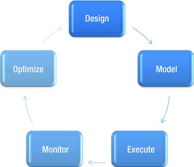
Figure 1-1. BPM phase order
Workflow Activities
At the beginning of this chapter I mentioned that a workflow is a list of predefined steps that are executed in a specific order to perform an outcome and that you can use them to model processes. Each step of a workflow is called an activity and one or more activities makes up a workflow. Just as the atom plays a role as the building block of the universe, activities are considered the basic building blocks that define a workflow. To demonstrate how activities are used and to show how easy it is to model as a workflow using activities, let’s look at an example of a simple process, such as going to the movies. When planning to go to a movie, the first steps are as follows:
- Check the times when the movie is showing.
- Order tickets, either at the theater or online.
- Pick up the tickets in order to enter the theater to see the movie.
Figure 1-2 models each of these steps as activities within a workflow. These are the basic steps that need to be taken for seeing a movie. By following them, you execute a workflow every time you want to see a movie. All workflows have a starting and ending point, and within this workflow each activity must be processed in sequential order. However, to maintain a level of flexibility for modeling processes, this is not a requirement for all workflows. A major benefit of the workflow is that others can also use it for seeing a movie, too. The concept of reuse does not have any real significance in this example, but the familiar analogy of movie-going helps to illustrate the principle of reusing code, where a workflow can be built once and used by other processes.

Figure 1-2. Workflow for going to a movie
Defining Requirements
Another benefit gained by modeling a process as a workflow is transparency, which grants the ability to see a process as a two dimensional model, illustrating the logic within the process. Have you ever heard that a picture is worth a thousand words? It’s the easiest way to communicate a process to others. Let’s look at modeling a workflow for a business process that transfers money from one bank account to another. In this case, there are no other requirements available for how this business process should work other than past experiences of transferring money. Figure 1-3 represents a workflow for transferring funds from a saving account to a checking account.
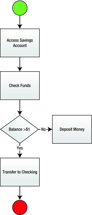
Figure 1-3. Workflow for transferring money
Figure 1-3 demonstrates that funds will be transferred from a savings account (once it is determined that more than one dollar is available within the account) into a checking account. If there is less than one dollar in the savings account, the transfer of funds activity will not execute within the workflow.
Workflows can also be used to flush out additional requirements by gaining transparency into a business process. For example, the bank might have additional rules around a mandatory minimal account balance that must be met before a certain amount of money can be transferred. Also, what credentials must be authenticated against before gaining access to the savings account?
I learned the importance of using workflows as a way to communicate requirements the first time I lead a team of developers on a project. We decided as a team that we would use workflows as way to communicate requirements not only to each other but with the client, too. This way we could make sure that the team had a clear understanding of what the client needed.
This became a real world exercise one day when I hit a brick wall while trying to understand the requirements being communicated to me from the client. For whatever reason, communicating verbally with the client was not working, so I finally drew what I thought were the requirements. By drawing the steps and decisions around the logic that the client and I were struggling to communicate verbally, we were able to finally understand each other.
The most important part of creating software is not actually writing the code, as most developers tend to think. Sometimes requirement gathering takes a back seat in software projects, but this is a recipe for disaster. Decisions for architecting a solution and designing how it will function can only be made after understanding what needs to be built. There is nothing more frustrating than trying to write software without knowing the full extent of the requirements. It’s no better than setting out to build a house when you don’t have the blueprints.
Sometimes a software project’s sponsors (those who drive the initiative and the direction of the software project) fail to recognize the importance of writing requirements. Sometimes they overlook the time that should be allocated for gathering requirements in their enthusiasm to reduce cost or save money within the project. Other times the omission is because of bad experiences in the past, where the process became unproductive and drawn out, putting a squeeze on project deadlines. However, if gathering requirements was not important, it would not be included within the software development life cycle (SDLC), the software industry standard of phases that should be followed when developing software.
The best practice for developing software enlists the SDLC to guide the process of development. Table 1-2 represents the phases that are most commonly used within a SDLC. Each phase of the cycle is equally important and depends on the previous phase. Therefore, the success for a software project primarily relies on how well each phase is executed.
Table 1-2. System Development Life Cycle
| Phase | Description |
|---|---|
| Planning | Building a case for initiating a software project to exceed the goals for project sponsors. |
| Discovery | Understanding the stakeholder’s business requirements so the project can be successful. |
| Analysis | Gathering and documenting user requirements around how the software should work and perform. |
| Design | Defining and documenting both physical and logical architecture based on gathered user requirements. |
| Testing | Testing the software to make sure it functions the way it should from the client’s perspective. |
| Deployment | Implementing the developed solutions within a production platform. |
The first two phases, Planning and Discovery, focus on understanding stakeholder goals and how goals will be met or even exceeded for the overall project.
The next phase, Analysis, focuses on gathering the requirements based on the stakeholder’s goals and how the software will function and perform. Many development teams struggle with the Analysis phase. Projects fail because development teams cannot communicate effectively or understand the process for defining requirements. A development team can have the best engineers on it, but a failure to explain to them what needs to be built can be catastrophic.
It is important to understand the types of requirements needed for architecting and developing a solution. Software requirements can be broken up into four areas.
- Business requirements: Goals defined by project sponsors against which the success of the project can be measured.
- User requirements: Functionality that must be implemented, allowing users to accomplish their objectives.
- Functional requirements: Detailed representation usually provided by the technical leadership to provide guidance through models and serve as the blueprints for how the software should be developed collectively by the team.
- Quality of service: Standards agreed upon for how developed software should scale and perform based on predefined metrics. These requirements are important when determining the overall architecture for the solution.
The key objective gained through modeling a process is to understand and learn more about the process while building a visual representation. Workflows are a natural tool for defining the different types of requirements previously mentioned.
Model Driven Development
If you are consistently building models for the requirements gathered before writing any code for the software projects you develop, you are applying model-driven engineering (MDE) or model-driven development (MDD)1. The models created are then used to drive the business logic that is written as code.
If you prefer a more agile approach, there is also agile model-driven development (AMDD). It builds models but applies an iterative approach for driving features of prioritized requirements to a deeper level, with iteration until all functionality is flushed out. Critics of MDD feel that the models generated become stale or obsolete as processes change; however, this is where BPM comes to the rescue by always adapting to changes within processes.
There are many tools available to model processes as workflows, and these give developers and architects the comfort of easily building diagrams without having to leave Visual Studio. Before the rich diagramming features released with Visual Studio 2010 (VS2010) Ultimate, developers had to look outside of Visual Studio for other tools for modeling workflows. Most used Microsoft Visio (and rightfully so as Visio’s templates cover just about every possible workflow). However, VS2010 Ultimate supports many diagrams, and these are covered in the next sections.
Component Diagrams
Component diagrams illustrate the tiers included within the physical architecture for a solution. Figure 1-4 illustrates a rental service and the components that make up the rental service’s architecture. It also illustrates how the components interact with each other. For instance, the ClientBrowser component’s HTTP interface requires services from the rental site to be able to use the rental service.
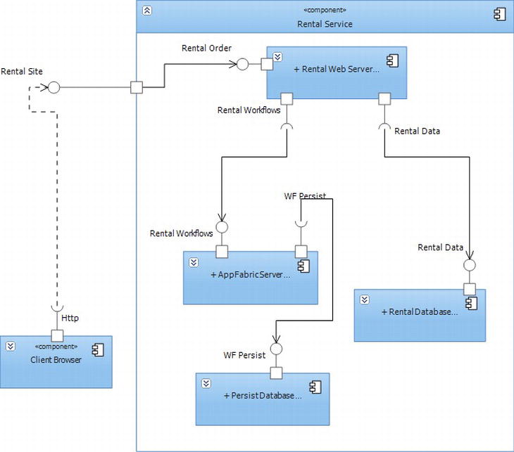
Figure 1-4. Component diagram for a rental service
Use Case Diagrams
Use cases model interaction between users (referred to as actors) and a logical grouping of functionality, sometimes referred to as asubsystem. Figure 1-5 illustrates a Jeep parts web site where customers can order parts for their car. First a customer must either create a profile or log in; then the customer gets extended functionality for creating an order. Creating the order includes processing the order, which also includes processing payment and later even refunding money if a customer wants to return part or all of an order.
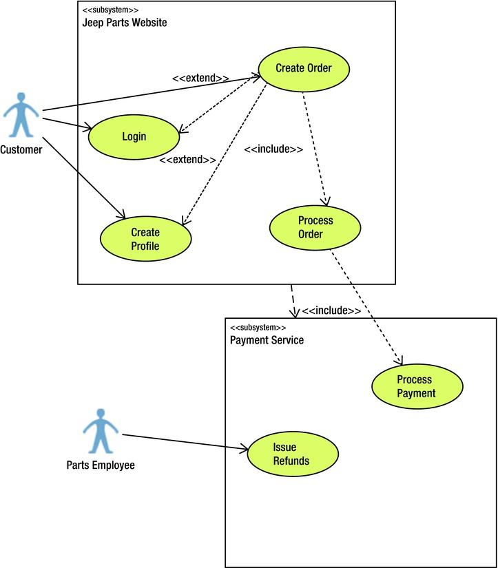
Figure 1-5. Component diagram for a rental service
Class Diagrams
Class diagrams model relationships for objects defined with code. Entities defined within a business domain are usually modeled in code to closely relate their role within the business. Figure 1-6 illustrates three classes that make up a part order. There is a composite relationship between the order and the order line item because an order contains an order line item. An order line item shows it has a relationship with an auto part based on the part’s ID and indicates that there can only be one part ordered per line item; however, many order line items can have the same part ordered.
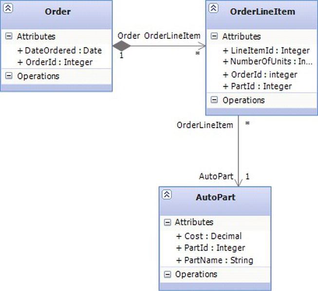
Figure 1-6. Component diagram for a rental service
Sequence Diagrams
Sequence diagrams show how processes interact within a system. Sequence diagrams can illustrate a deeper representation than a use case because they represent a full sequence for a process from beginning to end and provide clarity regarding the interaction of the participants involved. Figure 1-7 illustrates four participants and how they interact with each other when creating and processing a parts order.
- Customer
- Parts Order
- Inventory
- Credit Card Processing
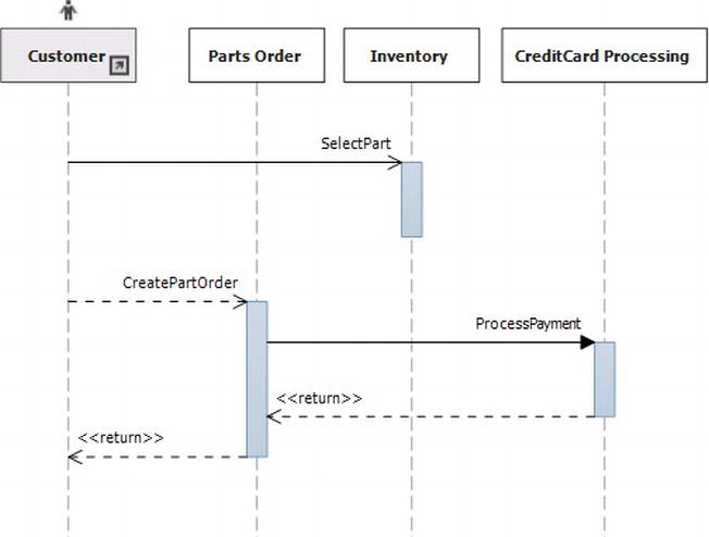
Figure 1-7. Processing a parts order
Activity Diagrams
Activity diagrams model business logic and work well for discovering additional user requirements that might not have been considered or thought through completely. Since activity diagrams can be used for modeling, they are a great tool for building workflows. Table 1-3 explains the symbols that are available within Visual Studio for diagraming activity diagrams.
Table 1-3. Activity Diagram Symbols
| Diagraming Symbols | Description |
|---|---|
| Initial Node | Indicates the beginning of the workflow. |
| Activity Final Node | Indicates the end of the workflow. |
| Action | A step within a workflow that is primarily used to model activity. |
| Object Node | Used to demonstrate transmission, buffering, filtering, and transformation of objects. |
| Comment | Used for commenting on the flow of the workflow. |
| Decision Node | Indicates more than one flow driven by a decision within the workflow. |
| Merge Node | Merges more than one flow into one outgoing flow. |
| Fork Node | Divides one thread into more than one concurrent thread. |
| Join Node | Joins concurrent threads into one outgoing thread. |
| Send Signal Action | Sends a signal to another system or activity. |
| Accept Event Action | Waits for a signal or event. |
| Call Behavior Action | Action that calls another activity. |
| Call Operation Action | Action that calls an operation. |
| Input Pin | Allows data to flow into an action. |
| Output Pin | Allows data to flow out of an action. |
| Activity Parameter Node | Parameters used to push data in and out of an activity. |
| Connector | Connects the flow between activities. |
Building an Activity Diagram
To build diagrams in Visual Studio you will need Visual Studio 11 Ultimate. Here are the steps for building diagrams in Visual Studio 11 Ultimate.
1. Open a new instance of VS11 and create a new project by clicking File ![]() New
New ![]() Project. Name the project “Apress.Example” and the solution “Apress.” It is common practice for the solution and project names to be different so the hierarchy from solution to project is easily recognized. By default the “Create directory for solution” checkbox is checked, which means that the file directory for the solution will automatically be created. Within the Installed Templates directory is a template called Modeling Projects. This is the type of project you will use to building diagrams (see Figure 1-8).
Project. Name the project “Apress.Example” and the solution “Apress.” It is common practice for the solution and project names to be different so the hierarchy from solution to project is easily recognized. By default the “Create directory for solution” checkbox is checked, which means that the file directory for the solution will automatically be created. Within the Installed Templates directory is a template called Modeling Projects. This is the type of project you will use to building diagrams (see Figure 1-8).
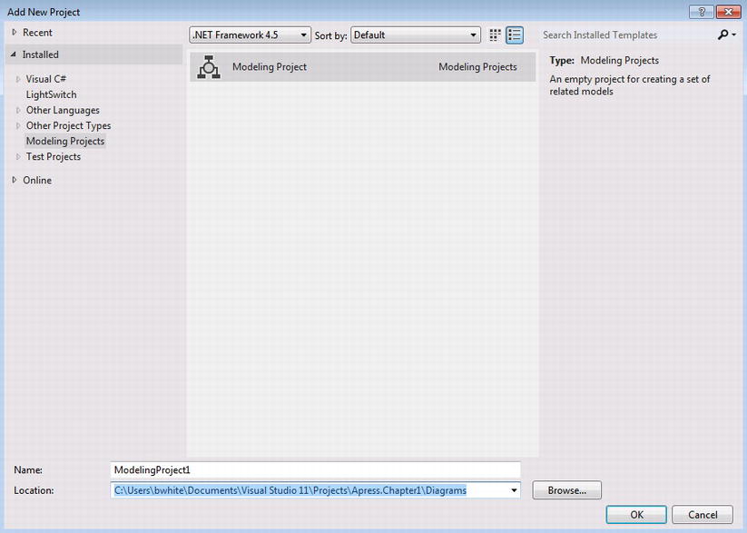
Figure 1-8. Creating a new modeling project
2. Add a new diagram to the project by right-clicking Apress.Example.Diagramming within the Solution Explorer. Add a new diagram by clicking Add ![]() New Item. Figure 1-9 shows all of the diagrams that can be added to the project. Since activity diagrams are closely related to the type of workflows you will be building using WF, select UML Activity Diagram as the type of diagram to build. Change the name for the new activity diagram to “CustomerOrder” and leave the extension as .activitydiagram.
New Item. Figure 1-9 shows all of the diagrams that can be added to the project. Since activity diagrams are closely related to the type of workflows you will be building using WF, select UML Activity Diagram as the type of diagram to build. Change the name for the new activity diagram to “CustomerOrder” and leave the extension as .activitydiagram.
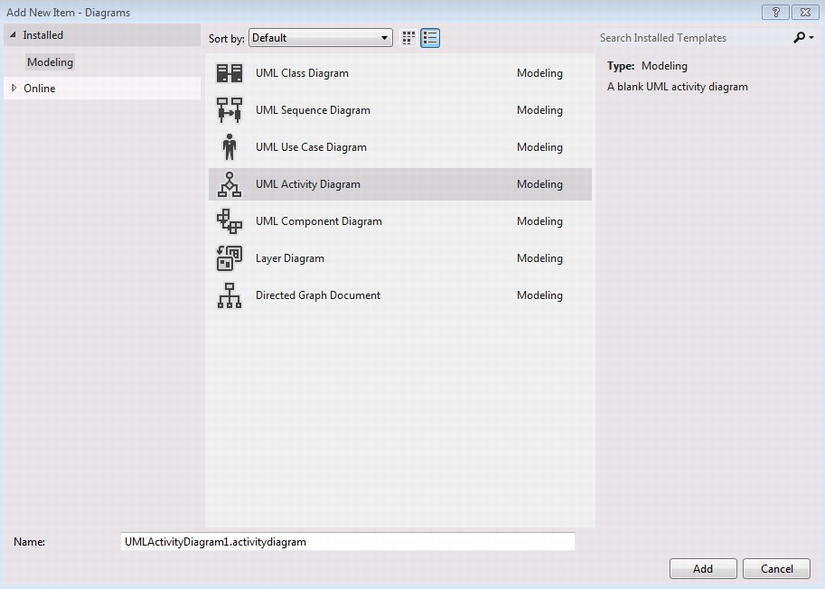
Figure 1-9. Adding a UML Activity Diagram
Before you start building the workflow for processing a customer order, let’s walk through the logic of processing a customer’s order. First, make sure the product ordered is in stock by checking the inventory.
- When a customer orders a product, there are two inventories that need to be checked.
- Local store
- Warehouse
- If the product is not in either of the inventories, get the product from the supplier’s inventory.
- Once the inventory is found, process payment.
![]() Tip When adding new items to a project, it is good practice to give the item a representative name. For instance, if you add a new activity diagram for a customer order, you could name it “actCustomerOrder." (However, there’s no need to do so in this case because its extension is descriptive enough.)
Tip When adding new items to a project, it is good practice to give the item a representative name. For instance, if you add a new activity diagram for a customer order, you could name it “actCustomerOrder." (However, there’s no need to do so in this case because its extension is descriptive enough.)
3. Click the Initial Node symbol within the toolbox (see Figure 1-10), and then click the canvas for the activity diagram to add it as part of the diagram.
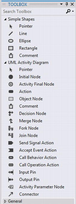
Figure 1-10. Activity diagraming activities
4. Click the Action symbol and then click the canvas of the activity diagram to add an action. Double-click within the Action symbol so the name can be changed to “Check Store Inventory.”
5. To connect the two symbols placed on the canvas, click the Connector symbol and then hover the mouse over the Initial Node that was already added to the canvas. While the mouse is hovering over the Initial Node, the mouse icon will change so the connection can be anchored. Click once to anchor the connection arrow and then click the Check Store Inventory action to add the connection.
6. Follow step 4 and add two more steps to the workflow. Name them “Check Warehouse Inventory” and “Check External Supplier.” At this point the diagram should look like Figure 1-11.
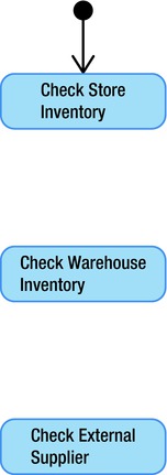
Figure 1-11. Activity diagram with steps
7. Next, add the logic that models the decisions for the workflow. Click the Decision Node symbol and then click the canvas between the Check Store Inventory and Check Warehouse Inventory steps. Follow the same steps to add a Decision Node between the Check Store Inventory and Check External Supplier steps.
8. Logic and decisions can now be added between the existing steps by using the Connector symbols. The connectors can be added quickly by clicking a Connector symbol and then clicking the step and decision that should be connected (see Figure 1-12).

Figure 1-12. Connecting steps and decision symbols
9. Descriptions for a Connector symbol can be added by clicking a connector arrow within the workflow. Add the description, “Not In Inventory” for the Connector arrow between the Decision symbol and the Action symbol Check Warehouse Inventory. This indicates that if inventory can’t be found for a customer order, the next available inventory should be checked.
10. If there is inventory from one of the locations in the workflow, based on the order for checking inventory, the order gets processed. This type of logic can be modeled using the Merge Node symbol. Add a Merge symbol to the workflow and place it on the right side of the workflow.
11. Add connections between the existing Decision symbols and the Merge Node. Add one more Connector symbol between the Check External Supplier step and the Merge Node symbol.
12. Add the description “Inventory Exists” for each connection to the Merge Node symbol.
13. Now that you have a flow for processing a customer’s order when inventory exists, add another Action symbol to the workflow and change its name to “Process Order.” Add another Connector symbol between the Merge Node symbol and Process Order step. This logic indicates that it is ok to process the order when the inventory exists. The finished workflow should now resemble the complete business logic represented in Figure 1-13.
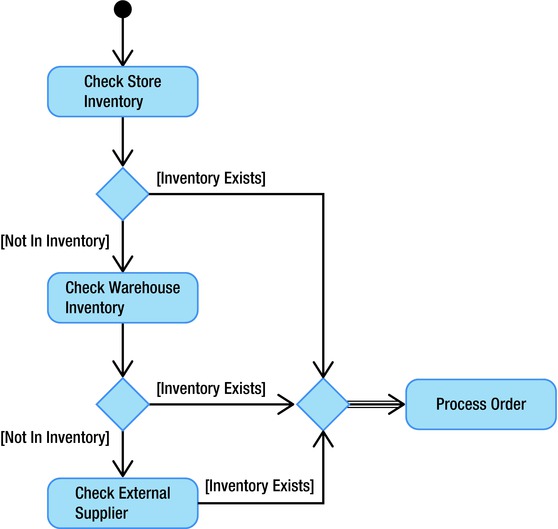
Figure 1-13. Complete process for customer order
![]() Tip Symbols can also be added to the workflow by right-clicking in the canvas of the workflow and selecting Add. A list of symbols will appear. Clicking any of them will automatically add them to the canvas.
Tip Symbols can also be added to the workflow by right-clicking in the canvas of the workflow and selecting Add. A list of symbols will appear. Clicking any of them will automatically add them to the canvas.
Workflow Technology
There is much to gain when applying workflows with a software development methodology, but the real power of workflows is building software from workflows. Technically workflow logic can still be done just by writing code, and sometimes simply using code is the best solution, but there are obstacles that a workflow technology like WF can help developers address.
Once a software project has completed the Analysis phase and has entered the Design phase, important decisions have to be made about the technologies and architecture of the solution. This is why understanding the requirements of a project are so important. Once developers understand the requirements, educated decisions can be made about the technologies that will help the project be successful and the architecture the team will use together to implement the solution.
WF was built to address certain requirements that were painstakingly complicated to implement.
- Long-running processes can be extremely complicated and may require to be executed continuously or within a certain schedule. An example of a long-running process is ordering something over the Internet and having the item shipped to a home address. Another example is the service maintenance required for hardware that can span over years.
- Declarative workflows allow developers to build workflows visually that perform complicated conditional logic and actions to reduce the amount of code and the complications for how code is implemented.
- Business domain activities are custom activities that are built to focus on an organization’s proprietary business.
- Rules-driven logic can also be added within the workflow or even modeled in a workflow. It can be modified during runtime or while the workflow is being processed by an application
- Human automation can integrate within the workflow so humans can make decisions for how the logic of the workflow should flow.
- Service-oriented architecture can be applied by building services from workflow rather than complex code.
- Workflow persistence provides the mechanism for releasing processing memory from workflows that are idle from either waiting for events or by logic that dictates that the workflow should go idle.
- Business processes monitoring provides automation for how information is gathered and stored, about the logic being processed, and for pertinent data being monitored.
Summary
Workflows are great for modeling business processes. However, to really gain value from using them, they should be applied with a methodology like business process management that helps guide the steps for modeling workflows and focuses on continuously making improvement to processes so they do not become stagnant.
As developers model business processes with workflows, they come to understand requirements quicker and can thus plan architecture and write code that is efficiently designed to meet or exceed the goals of stakeholders. Workflows also provide the transparency for the complicated business logic needed within software. Tools like Visio and Visual Studio ease the experience of designing and documenting workflows. By using a workflow technology like WF, code can be represented as business logic that is abstracted through declaratively building workflows that can be executed as code. Workflows running within an application can also be consistently changed at runtime and throughout the lifespan of the business processes they model.
Now that you understand why it is important to use workflows during software development, the rest of the book digs deeper into WF to show you how to gain the aforementioned benefits. Using WF within applications is truly a more effective way of architecting and developing software. The next chapter will focus on the components that make up the WF.
1 Model-driven architecture (MDA) is an industry standard maintained by the Object Management Group (OMG).