
A model of a system is the body of information gathered for the purpose of studying the system so that it can be better understood by the developers and maintainers of the system. When a system is modeled, the boundaries and identification of the entities, attributes, and activities performed by the system can be determined. Modeling is an important tool in the design process of any system. It is essential that developers fully understand the system they are developing. Modeling can reveal the hidden concurrency and opportunities where parallelism can be exploited.
In this chapter, we show you how to visualize and model your concurrent system using the UML. We will discuss diagraming techniques used to visualize and model concurrent systems from three perspectives:
The structural perspective
The behavioral perspective
The architectural perspective
The classes, objects, processes, threads, and systems used as examples in this chapter are used for exposition purposes and may or may not necessarily reflect actual classes, objects, or structures used in an actual system. This chapter should not be considered a primer for UML but rather an introduction to the diagrams used in this book focused on the UML notation used to design and document systems that utilize concurrency.
Unified Modeling Language (UML) is a graphical language used for modeling, visualizing, designing and documenting the artifacts of a system. It is the standardized specification language used to communicate and model different system paradigms such as Object-Oriented, agent-oriented, and event-driven systems. It uses symbols and notations to represent the components from different views and perspectives of the system.
The UML is called "unified" because it brought three of the most prominent modeling languages (Grady Booch's Approach, Ivar Jacobson's Object-Oriented Software Engineering (OOSE), and James Rumbaugh's Object Modeling Technique(OMT)). Although each was a complete systems, each had a particular focus. Each also had a weakness — they were not able to be a general-purpose modeling language for complex systems. Table 9-1 gives a brief definition of each of these modeling approaches and what their main contribution was to the UML standard. The purpose of the UML was to unify these methods into a definition that would provide to users a modeling system that was capable of capturing:
Conceptual to executable components of a software system utilizing object-oriented techniques
Simple to complicated mission-critical systems
This was true whether those users were people or machines. The first draft of the UML was released in early 1995, and a new version was released later that year. In 1997, the Object Management Group (OMG), an international consortium of companies active in the development of the Object-Oriented paradigm, made a request for proposal for a standard modeling language, and UML 1.0 was offered. Since then UML has become the de facto international standard modeling language revised and extended by OMG. Many interests over the years have contributed to the standard, and it has now been adopted for modeling not only Object-Oriented (OO) software systems but concurrent and distributed systems, engineering problems, and business structures and processes. OMG released version 2.0 in 2007.
Table 9.1. Table 9-1
Types | Description | |
|---|---|---|
Things | Structural
| Nouns of the model The static parts of the model representing elements that are conceptual or physical. |
Behavioral
| Verbs of the model Dynamic parts of the model representing behavior over time. | |
| Organizations parts of the model These are highest level of the model where decomposition can occur. | |
Annotational | Explanatory parts of the model Used for comments that describe element in the model. | |
Relationships | Dependency | Change to one element may affect the other. |
Association | A structural connection between elements (whole-part). | |
Generalization | The child element is a specialization of the parent element. | |
One element fulfills the contract of another element. | ||
Diagrams |
|
The UML grammar is based on three language primitives:
Things: The most basic components in a model
Relationships: Relate things with other things
Diagrams: Define a collection of things and their relationships
Table 9-1 shows how each of the three language primitives is broken down into its various components and types. As you can see, UML is a comprehensive language with many ways for representing a system. What we focus on in this chapter are the notations and diagrams of the language that you utilize when modeling a system with concurrent behavior.
When you are modeling the structure of a system, the focus will be on the static parts of a system such as objects, classes, and their attributes, services, organization, and composition, along with relationships those parts of the system will have with other entities in the system.
The class is the basic software component of an Object-Oriented system. A class is a model of a construct that includes its attributes and behaviors. It serves as a definition of a group or set of things that all share the same attributes and behaviors. A class can model something conceptual, a real-world physical entity, or a software construct.
A class modeling something conceptual is a scaled representation of a process, concept, or an idea for the purpose of analysis or experimentation. It is a scaled representation because a full model would be too difficult to create or not desirable. The nature of the analysis may be focused in a specific area, and therefore, a full-scale model is not necessary. An example of a class is a model of a molecule. The structure of a molecule and the distances and angles of chemical bonds are attributes of the class, and the chemical reactions and processes are the behaviors of the model. This molecule class simulates the characteristics of the real-world counterpart for the purpose of predicting and analyzing its behavior.
A class can model a real-world physical entity, process, task, or idea for the purpose of replacing it. In this, the model is not a scaled representation but duplicates all the functionality of the existing entity. This type of class models the real-world counterpart because the software model may be more efficient, accessible, or effective. For example, a class can model an accounting system or a calculator. A calcular class would have a display, a calculation, and an input mechanism for attributes. The calculator class would have to be able to parse the input, validate the input, perform the desired arithmetic operations, and then display the results.
A class can model software constructs. In this case, the model only has meaning within a software system. An example of modeling a software construct is a bitmapped image class. A bitmapped image class would have a header, number of bit planes, size, and vector of bits that represents each pixel of the image. The class would have to be able to display, read, and resize the image. Other software constructs that are modeled are datatypes. Datatypes such as floats, integers, and booleans have both attributes and a set of operations. These software constructs are used as utility and support classes for modeling a larger system such as an accounting system or a simple calculator. They can be used in any system regardless of the domain.
So, as you can see, classes can be used to model various types of entities in a software system. When you are modeling, it is important to be able to identify the constructs based on the structural, behavioral, or architectural view of the system. It is even necessary to model types of classes based on how they are used in the system. Some classes are useful when used as a blueprint that provides an interface policy for other classes, whereas other classes are useful as a base or ancestor class or a class just for a particular domain. Table 9-2 lists commonly found class types.
Table 9.2. Table 9-2
Description | |
|---|---|
Abstract | A base class that defines the blueprint for all its descendants; an object cannot be declared of this type. |
A standalone class that represents the end of an ancestor-descendant lineage. | |
Interface | A class that modifies or enhances the interface of another class or set of classes. |
A class that supplies the foundation for inheritance and polymorphism and contains no pure virtual functions. | |
A class created to simulate reality or some entity within a domain. | |
Useful programs for applications regardless of domain. | |
Generic holder of a set of objects with a defined set of operations to access them. | |
A class in which the type is parameterized with a defined set of operations to access and manipulate the objects. | |
A type and its operations. |
For instance, say that you are modeling a subsystem that identifies unrecognized words in a text file. The subsystem extracts words from a text file, determines if a word cannot be recognized, and then stores that word in a global container. Some classes in this subsystem are:
Word expert: Determines if a word is recognized, if not writes the word to a container
Unrecognized words list: Removes a given set of characters from a file
Dictionary lexicon: Contains all the recognized words
Text file: Contains the words to be recognized
Main agent: Creates word experts
Unrecognized word container: Contains all the unrecognized words
Misspelled and morphology agents: Agents that filter misspelled or word forms from the unrecognized words list
Each of these classes can be identified as a type of class:
The UML provides a graphical representation of a class. The representation of the class, or class icon, can show the attributes, services, and semantics of the class. The UML also provides a representation of types of classes such as datatypes, interface, template, and node classes. The simplest representation of a class is a rectangular box containing the name of the class. The simple name is the name of the class alone; a pathname is the name of the class with the name of the package where the class is contained prefixed to the name. The class name is text containing any number of letters and numbers. Punctuation can be used except for a colon that is used to separate the package from the class name. Class names are usually nouns or noun phrases taken from the vocabulary of the system that is being modeled. Class name should have the first letter of every word capitalized:
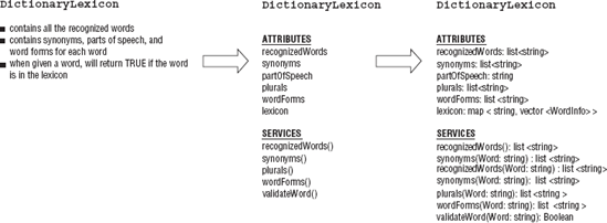
The class icon can be divided into three horizontal compartments. The top compartment contains the class name. The next two contain the attributes and services provided to the user of the class. An additional compartment at the bottom can describe the responsibility of the class. The responsibilities of the class are the obligations of the class stated in a few short sentences. For example, here are the basic responsibilities of the WordExpertAgent, UnrecognizedWords, and DictionaryLexicon classes:
WordExpertAgentDetermines if a word is recognized
Writes the unrecognized words to a global container
UnrecognizedWordsDetermines if unrecognized words are word forms or misspellings of recognized words by using
MorphologyAgentandMisspelledAgent
DictionaryLexiconContains all the recognized words
Contains the part of speech, synonyms, and word forms for each word
When given a word, returns
TRUEif the word is in the lexicon
These responsibilities can be transformed into the attributes and services of the class. The attributes are the named properties of the class, and the services or operations describe the behaviors of the class. Figure 9-1 shows how the responsibilities of the DictionaryLexicon were used to create some of the attributes and services of the class. The attributes are then transformed into datatypes and data structures, and services are transformed into methods. Attributes and service names use a lowercase for the first letter of the first word and uppercase for the first letter of any additional words.
The attributes, services, and responsibilities compartments can be labeled attributes, services, and responsibilities, respectively, to identify each compartment. If the attributes or services are not shown, then the compartment is displayed as empty. Figure 9-2 shows the various ways that a class can be represented, using the DictionaryLexicon class as an example.
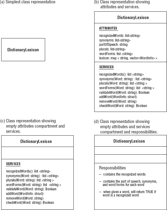
In Figure 9-2:
(a) shows the class in its simplest representation.
(b) shows the class name and its attributes and services.
(c) shows the class name and its services; the attributes compartment is empty to show that there are attributes but not shown.
(d) lists the responsibilities of the class.
The attributes compartment can specify the datatype and/or default value (if there is one) of the attributes for objects:
word: string
Word: string = "Car"
The datatypes and data structures for the attributes of the WordExpertAgent and DictionaryLexicon classes can be displayed:
synonyms: map <string,vector<string> >
synonymIterator:  map <string,vector<string> >::iterator
Methods can be shown with parameters and return type:
synonym(&X: map <string,vector<string> >): void
partOfSpeech(string &X): string
The synonym() method returns the synonyms of the word. DictionaryLexicon is a class that models a dictionary for a single domain. The synonyms for each word are stored in a vector. The map container maps a string (recognized word) with the vector of synonyms. The synonym() method returns void, whereas the partOfSpeech() method returns the part of speech of a word as a string.
You can use properties to describe attributes and methods. These properties help describe how an attribute or method can be used. Properties for attributes can be constant or modifiable:
changeableaddOnlyfrozen
There are four properties used to defined methods:
isQuerysequentialguardedconcurrent
These properties are listed in Table 9-3, along with a brief description of each.
Table 9.3. Table 9-3
Description | |
|---|---|
| No restrictions on modifying the values of this type of attribute. |
| For attributes with multiplicity > 1, additional values can be added; once created a value cannot be removed or changed. |
| Attribute's value cannot be changed once the object has been initialized. |
Properties for Services | Description |
| Execution leaves the state of the object unchanged; returns a value. |
| Uses synchronization to ensure sequential access to this method; multiple concurrent access to this method jeopardizes the integrity of the object. |
| Synchronized sequential access to this method is built into the object; integrity of the object is guaranteed. |
| Multiple concurrent access is permitted; integrity of the object is guaranteed. |
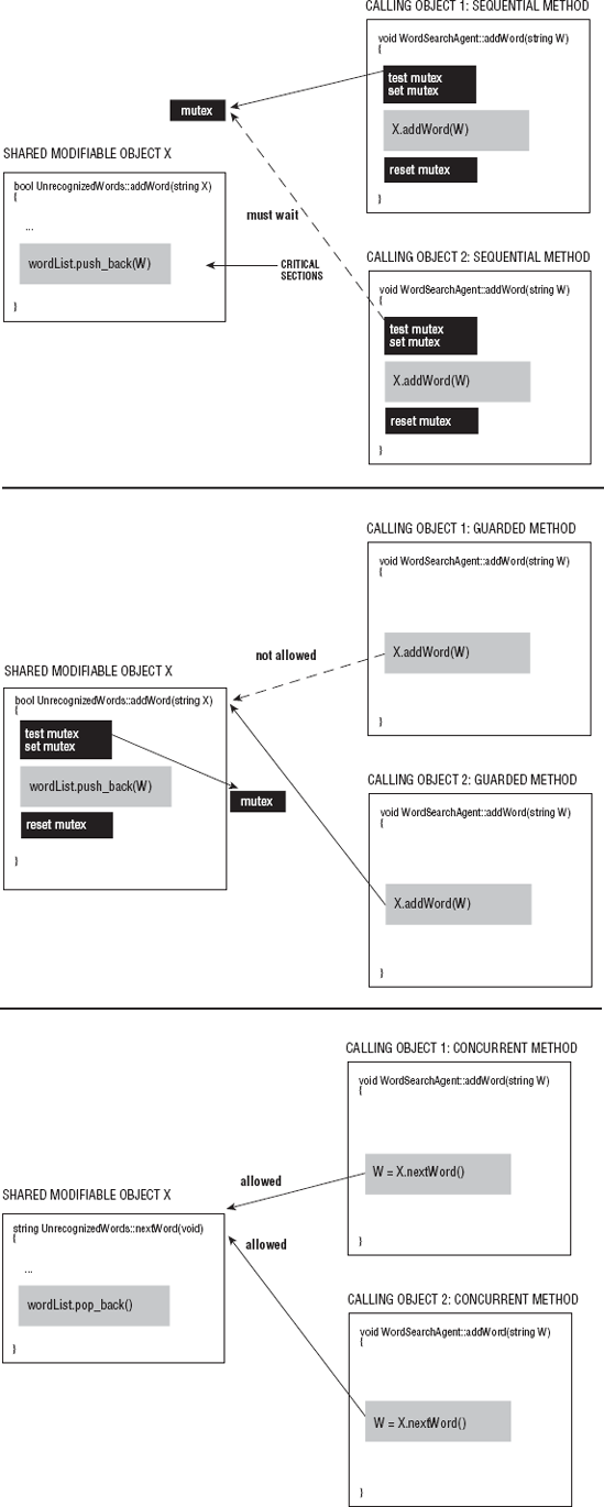
The sequential, guarded, and concurrent properties are concerned with methods involved with concurrency. For example, multiple WordExpertAgent objects can be created then passed individually to threads. Each WordExpertAgent object's method writes the unrecognized words to a shared container. The method that writes to the shared container has a critical section. Critical sections are regions of code where the code is accessing a shared modifiable object. When one method is in its critical section, other methods accessing that same object should not be in theirs. These properties (sequential, guarded, and concurrent) mark and manage methods that have or are critical sections by delineating whose responsible for synchronization.
The
sequentialproperty describes concurrent access where synchronization is the responsibility of the callers of the method. To synchronize access to the shared object, the mutex is tested by the calling objects. If the mutex is in use, then the calling object must wait until it is available. Once it is available, the mutex is set, and the operation that modifies the object can be performed. Once the operation is completed, the mutex is reset. The sequential operations do not guarantee the integrity of the object.The
guardedproperty describes a concurrent access where synchronization is built into the shared object; access is sequential.The
concurrentproperty describes a method that permits simultaneous use.
Methods that are guarded and concurrent guarantee the integrity of the shared modifiable object or data. Figure 9-3 shows where the synchronization occurs for sequential, guarded, and concurrent methods.
Here are examples of attributes and methods labeled with properties:
attributes
wordList: vector<string> {changeable}operations
addWord(word: string): boolean {guarded}
nextWord(void): string {isQuery, concurrent}
The attributes and operations in this example are defined by the UnrecognizedWords class that contains all the unrecognizable words. WordSearchAgent objects pass a word to addWord(), which adds the word to the list and returns TRUE. addWord() changes the state of the object. UnrecognizedWords objects are shared between all the WordSearchAgent objects. So, the addWord() is guarded. Synchronization is built into the object by using mutexes. nextWord(), on the other hand, returns the next word in the list. Calling this method does not change the state of the object; thus, it can use the isQuery, concurrent properties because this operation does not change the state of the object.
Another important property you can show is the visibility of attributes and operations. The visibility property describes who can access the attribute or invoke the operation. A character or symbol is used to represent the level of visibility. Visibility maps to the access specifiers of C++ and other languages. Access specifiers and visibility symbols are listed in Table 9-4.
Table 9.4. Table 9-4
Access Specifiers | Visibility Symbols |
|---|---|
| (+) Anyone has access. |
| (#) The class itself and its descendants have access. |
| (-) Only the class itself has access. |
The symbol is prepended to the service, method, or attribute name.
Some classes have many attributes and operations, so it may be best to organize them within their compartments. Ordering helps identify and navigate through the attributes and operations. The organization can be:
Ordering by access can be very useful to users. It communicates which attributes and operations are publicly accessible. Knowing which members are protected assists users who need to extend or specialize the class through inheritance. Visibility symbols or access specifiers can be used to organize attributes and services/methods by access.
Ordering attributes and operations based on the category helps in the modeling of the class. Organizing by category helps you determine what the basic operations of the class will be. Are you modeling a nice class? A nice class provides regular functionality to the class. This is the functionality that should be defined for a nice class:
The copy constructor, assignment operator, and destructor can be generated by the compiler for classes that need them, but do not define them. Some software designers believe that classes that are not nice classes have severely restricted behavior. Reusuable classes should have a nice interface when possible. The minimal standard interface defines categories that not only have the nice interface but also have these additional operations:
Input and output
Hash function
Query
Shallow and deep copy operations
Still, an argument can be made against a "minimal standard interface" or even a nice class. For example, a class may model an object that does not require any input or output operations.
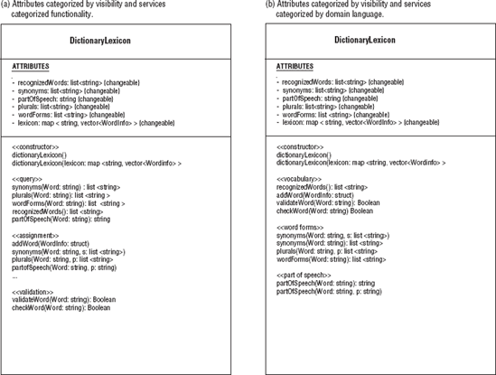
Attributes and services can be categorized according to the language of the domain. If you are modeling a class, the attributes and services are dictated by what is being modeled. For example, the DictionaryLexicon class might have categories based on services concerned with vocabulary, word forms, synonyms, and so on. Using these categories is very useful when you are starting to determine what attributes and operations a class requires. Other categories may be based on other properties of the methods or attributes such as:
attributes
static
const
operations
virtual
pure virtual
friend
query
concurrent
guarded
To show category names, you place them within left and right double angle brackets, (<<...>>).
Figure 9-4 shows examples of the different ways operations can be organized for the DictionaryLexicon class using the visibility symbols for the attributes and minimal standard interface, or domain categories for operations/services. In 9-4 (a) services are categorized by the function they fulfill for the class. In 9-4(b) services are categorized by the domain language of the class. All attributes have private visibility.
An object is an instantiation of a class. The object has an identity and gives values to attributes; this can be depicted using UML notation. The simplest representation of an object, an instance of a class, is a rectangle containing the name of the object underlined. This is called a named instance of a class. A named instance of a class can be shown with or without its class name:
| Named instance |
| Named instance with class name |
Since the actual name of the object may be known only to the program that declares it, you may want to represent anonymous instances of classes in your system documentation, with or without the pathnames. An orphan instance does not show the class name:
| Anonymous instance |
| Orphan instance |
Instances of a class may also show their current state, the static properties, and the dynamic ones in their own compartments. When the object changes dynamically, the object displays the new value of its properties. For example, Figure 9-5 shows the myWordSearch:WordSearchAgent object's attributes changing. To show the active or current object, a heavier line is used. More specifically, Figure 9-5 shows several versions of the myWordSearch object:
(a) shows the various notations for an instance.
(b) shows the instance's attributes changing but only one is the active object.
(c) denotes a collection of unintialized instances of the class called multiobjects.
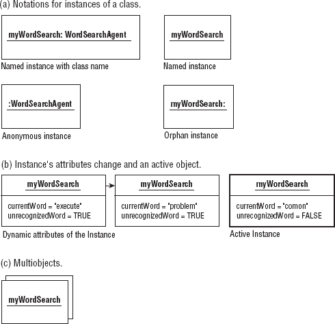
Multiobjects are a way to show multiple instances of a class exist. Depending upon the nature of the class or the relationship between two classes, you may want to restrict the number of instances of a class. Multiplicity is a specification that shows the allowable range of possible instances of a class. The multiplicity of a class can be noted on the class icon or an object. The multiplicity is placed in the upper-right corner of the icon. A class may have zero to an infinite number of instances. For example, a class with 0 instances is a pure abstract class. It cannot have any objects explicitly declared of its type. The number of instances may have an upper or lower bound. This may also be expressed in the diagram of a class. Figure 9-6 shows how multiplicity of a class can be represented (and how it can be represented between associated classes as well).
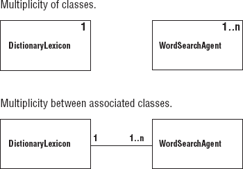
In Figure 9-6, the multiplicity of the WordSearchAgent class is 1. .n, meaning that the least number of WordSearchAgent objects in a system is 1 and the most that can exist is n (depending on the amount of space available), each containing a different set of words. The DictionaryLexicon has a multiplicity of one. It is a singleton class meaning only one exists in the system. Here are more examples of multiplicity notation and their meanings:
| |
| |
| One to an infinite number |
| |
| 0 to an infinite number |
| An infinite number |
Multiplicity can be shown between classes with association relationships. In Figure 9-6, there is one DictionaryLexicon to 1 to many instances of WordSearchAgents. This means there can be many WordSearchAgents performing searches on a DictionaryLexicon.
A template class is a mechanism that allows a type to be a parameter in the definition of the class. The template defines services that manipulate the datatype passed to it. The parameterized class is created in C++ by using the template keyword:
template <class Type > classname {...};The Type parameter represents any type passed to the template. Type can be a built-in datatype or a user-defined class. When Type is declared, the template is bound by the element passed to it as the parameterized type. For example, the Synonym is a map container that contains vectors of string objects. The map and the vector are template classes:
map <string,vector<string> > Synonym;
The map container has string as a key and vector of strings as the value. The vector container contains string objects. The map container can map any datatype to any other datatype, and vector containers can contain any datatype:
map <int, vector <string> > // maps a number to a vector of strings
map <int, string> > // maps a number to a string
vector <DictionaryLexicon> // a vector of dictionary objects
vector <map <int,string> > // a vector of maps that maps a number to
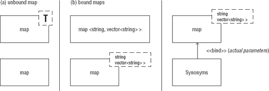
// stringTemplate classes are represented as rectangular boxes like any other class. There is an added notation of a parameterized type. It is represented as a dashed box displayed in the upper-right corner of the class icon. The template class can be unbound or bound to a type. The notation for representing an unbound template class is a dashed box displaying a capital T to represent the unbound parameterized type. A bound template class can be represented with implicit binding, the C++ syntax for declaring and binding a template class. For example, the template vector is implicitly bound with a string object:
vector <string>
This can be displayed in the class icon or <string> can be placed in the dashed box as the type for the template. Another approach is to use the dependency stereotype bind and a template object. The stereotype specifies the source that instantiates the template class by using the actual named parameterized type. This is called explicit binding. The stereotype indicator <<bind>> refines the template class by instantiating the parameterized type. Refinement is a general term to indicate a greater level of detail of something that already exists. Next to the stereotype indicator are the actual named parameters supplied by the template object. The template object has a dependency relationship with the template class. The template object can also be considered as a refinement of the template class. Figure 9-7 depicts the ways a template class can be represented, unbound and bound, for a map container.
The UML provides three classifications of relationships between classes:
Dependencies: A dependency relationship between two classes means that a change to the independent class may affect the dependent class.
Generalizations: A generalization relationship between two classes means that one is a general construct of a more specific type. The general construct is considered the parent or superclass, and the more specific construct is the child or subclass. The child inherits the properties, attributes, and operations of the parent but may define other attributes and operations of its own. The child is derived from the parent and can be used as a substitute for the parent class. A root or base class is a class with no parent.
Associations: An association is a structural relationship that specifies that objects are connected to other objects. Associations between objects can unidirectional or bidirectional. When objects have bidrectional associations, this means that object 1 is associated with object 2 and object 2 is associated with object 1. When objects have unidirectional associations, this means that object 1 is associated with object 2 but object 2 is not associated with object 1. An association between two elements (classes and so on) is called a binary association where an association between n elements is called an n-ary association.
Table 9-5 shows the various stereotypes that can be used for the dependency relationships.
Table 9.5. Table 9-5
Dependency Stereotypes | Description |
|---|---|
| The source instantiates the template target using the actual parameters. |
| The source has visibility into the target. |
| The source is an instance of the target. The dependency is used to define relationships between classes and objects. |
| The source creates instances of the target. This dependency is used to define relationships between classes and objects. |
| The source has a greater level of detail than the target. This dependency is used to define relationships between base class and the derived class. |
| The source depends on the public interface of the target. |
| The target is the same object as the source but at a later time in the lifetime of the source object. The target may be in a different state than the source. |
| The source invokes method of the target. |
| The source is an exact but independent copy of the target. |
| The source package is given the right to reference the elements of the target package. |
| The target use case extends the behavior of the source use case. |
| The source use case can include the behavior of the target use case at a location named by the source use case. |
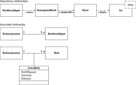
Many types of dependencies, generalizations, and associations exist. Each relationship classification has its own notation. The relationship notation is a solid or dashed line segment between the elements and may be accompanied with some type of arrowhead. To further define the relationship, stereotypes or adornments are used.
These stereotypes are labels that further describe the nature of the relationship. They are rendered as a named enclosed by guillemets and placed above or next to the element. For example, in Figure 9-8, which appears shortly:
<<bind>>
is placed next to the arrow depicting a dependency of the template object to the bound template class list. The <<bind>> dependency means the StrList is a list type supplying the parameter to the template string. UnrecognizedWords has a dependency with StrList in which it is an <<instanceOf>> of this type. WordSearchAgent <<use>> the UnrecognizedWords as a container of the words that it cannot recognize.
Adornments are textual or graphical items added to an element's basic representation. They are used to document details about that element's specifications. For example:
An association is depicted as a solid line connecting the same or different constructs. Use an association relationship when one construct is structurally related to another.
Navigation is a type of association. To depict navigation, the line between the elements becomes a dashed line with an arrow pointing to one of the elements in the association.
Dependency is represented as dashed directed line (with an arrow) between two elements, from the source pointing to the element it depends on, the target. Use a dependency relationship when one construct uses another.
A generalization relationship is rendered as a solid directed line with a large open arrowhead pointing to the parent or superclass. Use a generalization relationship when one construct inherits the behaviors and attributes from another construct. The child may change or modify the behaviors and attributes.
Table 9-6 and Table 9-7 list the stereotypes, constraints, and properties that can be applied to generalizations and associations, respectively.
Table 9.6. Table 9-6
Generalization | Description |
|---|---|
stereotype | |
| Child inherits the implementation of the parent but does not make public nor support the interface of the parent. |
constraints | |
| All children of the parent have been named and no more additional children can be derived. |
| All children of the parent have not been named; additional children can be derived. |
| The parent's objects may have no more than one of its children as a type. |
| The parent's objects may have more than one of its children as a type. |
Table 9.7. Table 9-7
Associations have another level of detail that can be applied to a general association or stereotype listed in Table 9-7:
Name: An association can have a name that is used to describe the nature of the relationship. A directional triangle can be added to the name to assure its meaning. The triangle points in the direction the name is intended to be read.
Role: A role is the face the class at the near end of the association presents to the class at the other end the association.
Multiplicity: Multiplicity notation can be used to state how many objects may be connected across an association. Multiplicity can be shown at both ends of the association.
Figure 9-8 also shows examples of association relationships between classes. DictionaryLexicon and WordSeacrchAgent have a multiplcity association of 1 to 1 ... n. This means there is only one DictionaryLexicon to 1 or many WordSearchAgents. The DictionaryLexicon can be searched by many WordSearchAgents. The LexicalEntry is the name of the association between DictionaryLexicon and Word. In this case, the named association LexicalEntry is also a class with attributes.
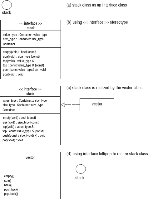
The interface of a class defines the outside world's interaction with an object through the methods and attributes that are exposed. Once a class has been designed, implemeted, and is in use, it may be necessary to change the interface of the class to accomodate a user. It may not be practical to actually change the existing interface of the class because it is already in use and will break existing code. An interface class is used to modify the interface of another existing class or set of classes. The modification makes the class easier to use, more functional, safer, or more semantically correct for a set of users. An example of an interface class are the container adaptors that are part of the Standard Template Library. The adaptors provide a new public interface for the deque, vector, and list containers. Example 9-1 shows the stack class. It is used as an interface class to modify a vector class.
Example 9.1. Example 9-1
//Example 9-1  Using the stack class as an interface class.

template < class Container >
class stack{
//...
public:
   typedef Container::value_type value_type;
   typedef Container::size_type size_type;
protected:
Container c;
public:
bool empty(void) const {return c.empty();}
size_type size(void) const {return c.size(); }
value_type& top(void) {return c.back(); }
const value_type& top const {return c.back(); }
void push(const value_type& x) {c.push.back(x); }
void pop(void) {c.pop.back(); }
};The stack is declared by specifying the Container type:
stack <vector< T> > Stack;
In this case, the Container is a vector, but any container, such as a deque and list, that defines these operations:
empty()
size()
back()
push.back()
pop.back()
can be used as the implementation class for the stack interface class:
stack < list< T> > Stack;
stack < deque< T> > Stack;
The stack class supplies the semantically correct interface traditionally accepted for stacks:
push()
pop()
top()
Multiple notations can be used to represent an interface class, each showing various levels of detail. Figure 9-9 shows the multiple notations for interface classes:
(a) shows the
stackas an interface class.(b) shows the stereotype indicator
<<interface>>displayed in the class symbol above the name of the class to denote that this is an interface class. This example shows the attributes and methods of the class. The letterIcan be prepended to the name of the interface class and all of its operations to further distinguish it from other classes.(c) shows the realization of a template class. It is read as "the stack class is realized by the vector class." Realization can be used to show the relationship between the
stackand the class with which it interfaces. Realization is a semantic relationship between classes in which one specifies a contract (interface class) and the other class carries it out (implementation class). Here, thestackclass specifies the contract, and thevectorclass carries it out. A realization relationship is depicted as a dashed line between the two classes with a large open arrowhead pointing to the interface class or the class that specifies the contract.(d) showsthe relationship between the interface class and its implementer depicted with the interface lollipop notation.
As you can see, classes and interfaces can be used as building blocks to create more complex classes and interfaces. In a parallel system, you may have many large and complex structures collaborating with other structures thus creating a society of classes and interfaces working together to accomplish the goals of the system. The collection of elements together with their interactions form a collaboration. These building blocks can include the structural and behavioral elements of the system. A request from a user to perform a particular task may involve many objects working together. Other tasks can be accomplished by those same objects working with other elements. Understanding that certainly makes apparent the benefits of well-defined resuable classes that can be used in different ways in the same system or in completely different systems. The collaboration has two parts:
A structural part that focuses on the way the collaborating elements are organized and constructed
A behavioral part that focuses on the interaction between the elements
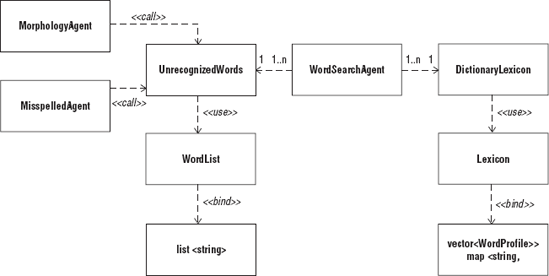
Figure 9-10 shows an example of the structural part of the agent-based Lexicon system. In this colloboration, all of the classes used have some type of dependency relationship. For example, MorphologyAgent and MisspelledAgent call methods in UnrecognizedWords, Lexicon binds the template map, and UnrecognizedWords contains a word list that binds the list template. The WordSearchAgent has a 1. .n relationship with UnrecognizedWords. The structural part of a collaboration consists of any combination of classes and interfaces, components and nodes. As you can see in Figure 9-10, a system may contain many collaborations. A single collaboration is unique in the system, but the elements of a collaboration are not. The elements of one collaboration may be used in another collaboration using a different organization and performing a different functions. In this particular collaboration, WordSearchAgent is used to find unrecognized words in a list. It could also be used to find words of a particular domain if it were to use a different Lexicon.
The behavioral view of a system focuses on the dynamic aspects of that system. This view examines how the elements in the system behave as it interacts with other elements of the system. Here is where concurrency emerges as elements interact with other elements. The diagramming techniques discussed in this section are the ones used to model:
The lifetime of the behavior of an object
Behavior of objects that work together for a particular purpose
Flows of control focusing on an action or a sequence of actions
Synchronization and communication between elements
Collaborating objects are objects involved with each other to perform some specific task. They do not form a permanent relationship. The same objects can be involved with other objects working together to perform other tasks. Collaborating objects can be represented in a collaboration diagram. Collaboration diagrams have a structural part and an interactive part. The structural part has already been discussed. The interaction part is a graph where all of the participating objects are vertices. The connections between the objects are the arcs. The arcs can be adorned with messages passed between the objects, method invocations, and stereotype indicators that express more details about the nature of the connection.
The connection between two objects is a link. A link is a type of association. When two objects are linked, actions can be performed between them. The action may result in a change of the state of one or both objects. The following table shows examples of the types of actions that can take place.
An object can be created. | |
An object can be destroyed. | |
An operation of an object can be invoked by another object or itself. | |
A value is returned to an object. | |
A signal may be sent to an object. |
When any method is invoked, the parameters and the return value can be expressed. Other actions can take place if specified.
The following actions can take place if the receiving object is visible to the calling object. Stereotypes can be used to specify why the object is visible.
The object is visible because an association exists (very general). | |
| The object is visible because it is a parameter to the calling object. |
| The object is visible because it is has local scope to the calling object. |
| The object is visible because it has global scope to the calling object. |
| The object calls its own method. |
Other stereotypes and adornments appropriate for associations can be expressed.
When a method is invoked, this may cause a number of other methods to be invoked by other objects. The sequence in which the operations are performed can be shown by using a sequence number combination and a colon separator prepended to the method. The sequence number combination expresses what sequence the method is associated with and the time order number in which the operation takes place. For example, Figure 9-11 shows a collaboration diagram that uses the sequence numbers.
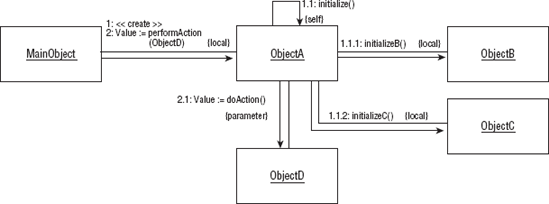
In Figure 9-11, MainObject performs two operations in sequence:
1: <<create>>
2: Value:= performAction(ObjectF)
In operation 1, MainObject creates ObjectA. ObjectA is local to the MainObject by containment. This initiates the first sequence of operations in a nested flow of control. All operations that are a part of this sequence use the number 1 followed by the time order number in which the operation takes place. The first operation of sequence 1 is:
1.1: initialize()
ObjectA invokes its own operation. This is expressed by linking the object to itself and by using the {self} stereotype indicator. The ObjectA::initialize() operation also causes the beginning of another sequence of actions:
1.1.1: initializeB()
1.1.2: initializeC()
in which two other objects local to ObjectA initialize methods are called. The operation:
2: performAction(ObjectD)
is the beginning of another nested sequence. ObjectA invokes ObjectD's operation:
2.1: doAction()
ObjectA can invoke this operation because ObjectD is a parameter (passed by MainObject) as the stereotype {parameter} indicates. A value is returned to ObjectA, and a value is returned to MainObject. Besides sequence number combinations, these nested flows of controls are further enhanced by using a line with a solid arrowhead pointing in the direction of the flow of the sequence.
Concurrency within an application can be implemented by using multitasking or multithreading. Multitasking allows more than one process to execute at the same time, whereas multithreading allows a single process to perform more than one task at the same time using multiple threads. When a process is divided into multiple tasks and each task is executed by a thread, the process is said to be multithreaded. The thread is a flow of control executing within the process's address space. Each process has at least one thread, the main thread.
When using the UML, each independent flow of control is considered an active object. An active object is an object that owns a process or thread. Each active object can initiate control activity. An active class is a class whose objects are active. Active classes can be used to model a group of processes or threads that share the same data members and methods. The objects of your system may not have a one-to-one correlation with active objects. When dividing your program up into processes and threads along object lines, an object's methods may execute in a separate process or execute on separate threads. Therefore, when modeling such an object, it may be represented by several active objects. This relationship between static and active objects can be represented by using an interaction diagram. Threads and processes can be represented directly as active objects.
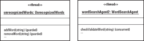
The UML represents an active object or class the same way a static object is represented except it has a heavier line tracing the perimeter of the rectangle. Two stereotypes can also be used:
process
thread
These stereotype indicators can be displayed to show the distinction between the two types of active objects. Figure 9-12 shows two active objects, both are threads. Each thread executes methods of unrecognizedWords and wordSearchAgent2.
In a concurrent system, you have multiple flows of control. Each flow of control is based on a process or a thread controlling the activity. These processes and threads may be executing on a single computer system with multiple processors. An active object or class is used to represent each flow of control. When the active object is created, an independent flow of control is initiated. When the active object is destroyed, the flow of control is terminated. Modeling the multiple flows of control in your system helps you with the management, synchronization, and communication among them.
In a collaboration diagram, sequence numbers and solid arrows are used to identify flows of controls. In a collaboration diagram that consists of active objects in a concurrent system, the name of the active object is preprended to the sequence numbers of the operations peformed by the active object. Active objects can invoke methods in other objects and suspend execution until the function returns or can continue to execute. Arrows are used not to show just the direction of the flow of control but also the nature of it. A solid arrowhead is used to represent a synchronous call and a half-stick arrowhead is used to represent an asynchronous call. Since more than one active object can invoke the operation of a single object, the method properties:
sequentialguardedconcurrent
can be used to describe the synchronization property of that method.
Figure 9-13 shows a collaboration of several active objects. In this diagram, these objects are working together to produce a list of unknown words. The mainAgent is used to record and coordinate the preliminary work and resulting list of unknown words produced by the active object problem solvers.
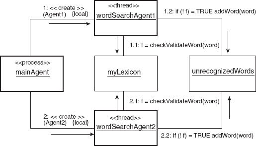
The myLexicon and unrecognizedWords objects are accessed concurrently by two agents. Both objects are visible to all the agents in this collaboration. The wordSearchAgents invoke the methods of the unrecognizedWords object:
wordSearchAgent1:unrecognizedWords.addWord(string word)
WordSearchAgent2:unrecognizedWords.addWord(string word)
The wordSearchAgents also invoke the methods of the myLexicon object:
wordSearchAgent1:myLexicon.validateWord(string &X)
WordSearchAgent2:myLexicon.validateWord(string &X)
The WordSearchAgents are concurrently invoking unrecognizedWords object's operation. unrecognizedWords addWord() has a guarded property and, therefore, is safe to call simultaneously. myLexicon.validateWord() does not modify the object and is also safe to call simultaneously.
Whereas a collaboration diagram focuses on the structural organization and interaction of objects working together to perform a task or operation or to realize a use case, a sequence diagram focuses on the time ordering of method invocation or procedures involved in a particular task, operation, or use case. In a sequence diagram, the name of each object or construct involved is displayed in its own rectangular box. The boxes are placed at the top along the x-axis of the diagram. You should only include the major players involved and the most important function calls because the diagram can quickly become too complicated. The objects are ordered from left to right starting from the object or procedure that initiates the action to the most subordinate objects or procedures. The calls are placed along the y-axis from top to bottom in time order. Vertical lines are placed under each box representing the lifeline of the object. Solid arrowhead lines are drawn from the lifeline of one object to the lifeline of another representing a function call or method invocation from the caller to the receiver. Stick arrowhead lines are drawn from the receiver back to the caller representing a return from a function or method. Each function call is labeled at the minimum with the function or method name. The arguments and control information, like the condition in which the method is invoked can also be displayed. For example:
if(!Unrecognized)
checkTransposes()
The function or method will not be performed unless the condition is true. Methods that are to be invoked several times on an object, like reading values from a structure, are preceded by an iteration marker (*).
Figure 9-14 shows a sequence diagram of some of the objects involved in the Lexicon system. Only some of the objects are shown to avoid a complicated diagram. When you are using the sequence diagram for concurrent objects or procedures, activation symbols are used. An activation symbol is a rectangle that appears on the object's lifeline. This indicates the object or procedure is active. These are used when an object makes a call to another object or procedure and does not block. This shows that the object or procedure is continuing to execute or be active. If an object is not active, a dashed line is used. In Figure 9-14, the misspelledAgent object is always active whereas the mainAgent becomes inactive after it has created the misspelledAgent. Once unrecognizedWords and myLexicon have been created, they do not become active until misspelledAgent invokes nextWord() and removeWord().
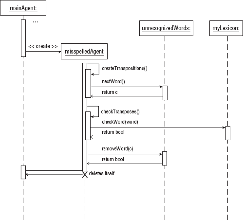
To indicate an object has called one of its own methods, a self-delegation symbol is used. This is a combination of an activation symbol and a call arrow. An activation symbol is overlapped on the existing activation symbol. A line proceeds from the original activation symbol with an arrow pointing to the added activation symbol. In Figure 9-14, self-delegation occurs for the misspelledAgent when it call its methods createTranspositions() and checkTransposes(). The checkTransposes method passes a transposition of the original word to myLexicon, which checks to see if this word is in the list of recognizable words. This method is called iteratively until Unrecognized is FALSE, which means the transposed word has been identified as the correct spelling of the original word. If the transposed word has been recognized, the original word is removed.
The UML can be used to model the activities performed by objects involved in a specific operation or use case. This is called an activity diagram. It is a flowchart showing the sequential and concurrent actions or activities involved a specific task, step by step. The arrows trace the flow of the control for the activities represented in the diagram. Collaboration diagrams emphasize the flow of control from object to object, sequence diagrams emphasize the flow of control in time order, and the activity diagram emphasizes the flow of control from one action or activity to another. The actions or activities change the state of the object or return a value. The containment of the action or activity is called an action or activity state. They represent the state of the object at a particular instant in the flow of control.
Actions and activities differ.
Actions cannot logically be decomposed or interrupted by other actions or events. Examples of actions are creating or destroying an object, invoking an object's method, or calling a function in a procedure.
An activity can be decomposed into other activities or even another activity diagram. An example of an activity is a program, a use case, or a procedure. Activities can be interrupted by an event or other activities or actions.
An activity diagram is a graph in which the nodes are actions or activities and the arcs are triggerless transitions. Triggerless transitions require no event to cause the transition to occur. The transition occurs when the previous action or activity has completed. The diagram comprises decision branches, starts, stops, and synchronization bars that join or fork several actions or activities. Both action and activity states are represented the same way. To represent an action or activity state, the UML uses the standard flowchart symbol used to show the enter and exit point of the flowchart. This symbol is used regardless of the type of action or activity occurring. However, we prefer to use the standard flowchart symbols that distinguish input/output actions (parallelogram) from processing or transformation actions (rectangle). The description of the action or activity as a function call, expression, phrase, use case, or program name is displayed in the action symbol used. An activity state may in addition show the entry and/or exit action. The entry action is the action that takes places when the activity state is entered. The exit action is the action that takes places just before exiting the activity state. They are the first and last actions to be executed in the activity state, respectively.
Once an action has completed, a transition occurs in which the next action takes place immediately. The transition is represented as a directed line from one state with a stick arrow pointing to the next state. A transition pointing to a state is inbound and a transition leading from a state is outbound. Before the outbound transition occurs, the exit action, if it exists, executes. After an inbound transition, the entry action for the state, if it exists, executes. The start of the flow of control is represented as a large solid dot. The first transition leads from the solid dot to the first state in the diagram. The stopping point or stop state of the activity diagram is represented as a large solid dot inside a circle.
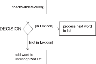
Activity diagrams, like flowcharts, have a decision symbol. The decision symbol is a diamond with one inbound transition and two or more outbound transitions. The outbound transitions are guarded conditions that determine the path of the flow of control. The guarded condition is a simple boolean expression. All of the outbound transitions should cover all of the possible paths from the branch. Figure 9-15 shows the decision symbol used in determining whether a knowledge source should be constructed, in determining whether a word should be added to the unrecognized word list.
You may find that there exists more than one flow of a sequence of actions or activities occurring concurrently after an action or activity has completed. In contrast to a flowchart, the UML defines a symbol that can be used to represent the instant where multiple flows of controls occur concurrently. A synchronization bar is used to show where single path branches off or forks into parallel paths and where parallel paths join. It is a thick horizontal line in which there can be multiple outbound transitions (forking) or multiple inbound transitions (joining). Each transition represents a different path. Outbound transitions from a synchronization bar signify an action or activity state has caused multiple flows of control to occur. Inbound transitions into a synchronization bar signify the multiple flows of control need to be synchronized. A synchronization bar is used to show that the paths are waiting for all paths to meet and join into a single flow or path.
In Figure 9-16, mainAgent creates two concurrent flows of control by creating two WordSearchAgents. After these these agents have completed, they are joined again into a single flow of control, where the mainAgent then creates a MorphologyAgent.
The diagram is divided into separate sections called swimlanes. In each swimlane, the actions or activities of a particular object, component, or use case occur. Swimlanes are vertical lines that partition the diagram into sections. A swimlane for a particular object, component, or use case specifies the focus of activities. An action or activity can occur only in a single swimlane. Transitions and synchronization bars can cross one or more swimlanes. Actions or activities in the same lane or different lanes but at the same level are concurrent. Figure 9-16 shows the activity diagram with swimlanes.
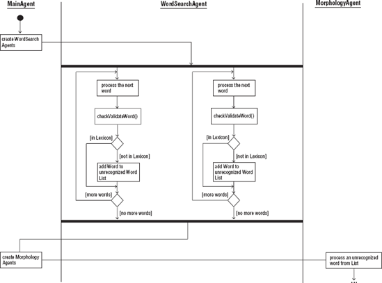
The purpose of this activity diagram is to model the sequence of actions involved in a mainAgent and other objects involved in producing the unknown word list for the agent-based Lexicon system. Concurrency occurs with the WordSearchAgents. The synchronization bar is in WordSearchAgent's swimlane. When there are no more words to process, then the flow of control for these agents is relinquished, and the flow of control returns back to the main thread, mainAgent.
State machines depict the behavior of a single construct, specifying the sequence of transformations during its lifetime as it responds to internal and external events. The single construct can be a system, a use case, or an object. State machines are used to model the behavior of a single entity. An entity can respond to events such as procedures, functions, operations, and signals. An entity can also respond to elapses in time. Whenever an event takes place, the entity responds by performing some activity or taking some action resulting in a change of the state of the entity or the production of some artifact. The action or activity performed depends upon the current state of the entity. A state is a condition the entity is in during its lifetime as a result of performing some action or responding to some event.
A state machine can be represented in a table or directed graph called a state diagram. Figure 9-17 shows a UML state diagram for the state machine of a process.
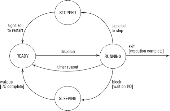
Figure 9-17 shows the states some process progresses through while it is active in the system. The process can have four states: ready, running, sleeping, and stopped. There are eight events that cause the four states of the process. Three of the events occur only if a condition is met.
The block event occurs only if the process requests I/O or it is waiting for an event to occur. If the block event occurs, it triggers the process to transform from a running state to a sleeping state.
The wakeup event occurs only if the event takes place or the I/O has been completed. If the wakeup event occurs, it triggers the process to transform from a sleeping state (source state) to a ready state (target state).
The exit event occurs only if the process has executed all its instructions. If the exit event occurs, it triggers the process to transform from a running state to a sleeping state.
The remaining events are external events and not under the control of the process. They occur for some external reason, triggering the process to transform from a source to a target state.
The state diagrams are used to model the dynamic aspects of an object, use case, or system. The sequence, activity, interactive collaboration diagrams, and now the state diagram are used to model the behavior of the system or object when it is active. Structural collaboration and class diagrams are used to model the structural organization of an object or system. State diagrams are good to use to describe the behavior of an object regardless of the use case. They should not be used to describe the behavior of several interacting or collaborating objects. They should be used to describe the behavior of an object, system, or use case that goes through a number of transformations and that on which more than one event can cause a single transformation to occur. These are constructs that are very reactive to internal and externals events.
In the state diagram, the nodes are states, and the arcs are transitions. The states are represented as rounded-corner rectangles in which the name of the state is displayed. The transitions are lines connecting the source and target states with a stick arrow pointing to the target state. There are initial and final states.
The initial state is the default starting point for the state machine. It is represented as a solid black dot with a transition to the first state of the state machine.
The final state is the ending state of the state machine, indicating it has completed or the system, use case, or object has reached the end of its lifeline. It is represented as a solid dot embedded in a circle.
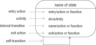
A state has several parts. Table 9-8 lists the parts of a state.
Table 9.8. Table 9-8
A state can be represented simply by displaying the name of the state at the center of the state symbol. If other actions are to be shown inside the state symbol, the name of the state should appear at the top in a separate compartment. The actions and activities are listed below this compartment and are displayed in this format:
label [Guard] / action or activity
For example:
do / validate(data)
The do is the label used for an activity to be performed while the object is in this state. The validate(data) function is called with data as the argument. If an action or activity is a call to a function or method, the arguments can be displayed.
The Guard is an expression that evaluates to true or false. If a condition evaluates to true, the action or activity takes place. For example:
exit [data valid] / send(data)
The exit action send(data) is guarded. The expression data valid is evaluated to be true or false. Upon exiting the state, if the expression is true, then the send(data) function is called. The Guard is always optional.
Transitions occur when an event takes place. This causes the object, system, or use case to transform from one state to another state. Two transitions can occur that do not cause a change in the state of the object, system, or use case. They are:
Self-transition: With a self-transition, when a particular event occurs, this triggers the object to leave the current state. When exiting, it performs the exit action (if any) and then performs whatever action is associated with the self-transition (if any). The object reenters the state, and the entry action (if any) is performed.
Internal transition: With an internal transition, the object does not leave the state and therefore no entry or exit actions are performed.
Figure 9-18 shows the general structure of a state with exit and entry actions and do activity along with internal and self-transitions. A self-transition is represented as a directed line that points back to the same state.
A transition between different states indicates that there is a relationship or path that exists between them. From one state an event can occur or a condition can be met that causes the object to be transformed from one state (source state) to another state (target state). The event triggers the transition of the object. A transition may have several concurrently existing source states. If so they are joined before the transition occurs. A transition may have several concurrently existing target states in which a fork has occurred. Table 9-9 lists the parts of a transition. A transition is rendered as a directed line from the source state pointing to the target state. The name of the event trigger is displayed next to the transition. Like actions and activities, events for transitions can also be guarded. A transition can be triggerless meaning no special event occurs that causes the transition to take place. Exiting the source state, the object immediately makes the transition and enters the target state.
Table 9.9. Table 9-9
Parts of a Transition | Description |
|---|---|
Target state | The state the object enters after a transition occurs. |
Source state | The original state of the object; when a transition occurs, the object leaves the source state. |
Event trigger | The event that causes the transition to occur. A transition may be triggerless, in which the transition occurs as soon as the object has completed all activities in the source state. |
A boolean expression associated with an event trigger. When it evaluates to True, the transitions occurs. | |
Action | An action executed by the object that takes place during a transition; it may be associated with an event trigger and/or guard condition. |
A substate can be used to further simplify the depiction of modeling the behavior of a concurrent system. A substate is a state contained inside another state called a superstate or composite state. This representation means a state can be further broken down into one or more substates. These substates can be sequential or concurrent. With concurrent substates, each state machine represented exists in parallel as different but concurrently existing flows of control. Each substate is separated by a dashed line. This is true for the WordSearchAgent objects in the example used throughout this chapter. Each object is processing all the words in its local list. The states for these objects are in a superstate called "building the unrecognized words list".
Each substate is contained in a separate compartment. The substates are synchronized and joined before exiting the composite state. When one substate has reached its final state, it waits for the other state to reach its final state, then the substates are joined back into one flow. Figure 9-19 shows a state diagram for Lexicon agent-based system.
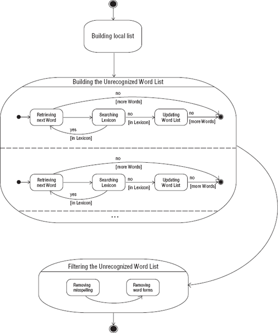
In Figure 9-19, there is another composite state called "Filtering the Unrecognized Word List". The substates in this composite state are sequential; they are not executed concurrently. First, the misspelled words are removed, and then the word forms of recognized words are removed.
A system is composed of many elements, including subsystems organized into a collaboration to accomplish some purpose. It is an aggregation of constructs joined in some regular interaction. The diagraming techniques discussed in this chapter allow the developer to model a single system from different viewpoints, from different levels, and from different flows of control to assist in the design and development of the system. In this section, we discuss modeling and documenting the system as a whole, meaning that the major components or functional elements can be depicted at the highest level. The diagraming techniques discussed in this section are the ones used to model the architecture of the system.
Although this is the last section in this chapter, modeling and documenting the whole system would be the first level of designing and developing a system.
When modeling and documenting the architecture of a system, the view of the system is the highest level. Grady Booch, James Rumbaugh, and Ivar Jacobson define architecture as:
The set of significant decisions about the organization of a software system, the selection of the structural elements and their interfaces by which the system is composed, together with their behavior as specified in the collaboration among those elements, the composition of these structural and behavioral elements into progressively larger subsystems, and the architectural style that guides this organization — these elements and their interfaces, their collaborations, and their composition. [Booch, Rumbaugh, and Jacobson, 1999]
Modeling and documenting the architecture captures the system's logical and physical elements along with the structure and behavior of the system at the highest level.
The architecture of the system is a description of the system from a distinct view that focuses on the structure and organization of the system from that aspect. The views are as follows:
Use case: Describes the behavior of the system presented to end users
Process: Describes the processes and threads used in the system's mechanisms of concurrency and synchronization
Design: Describes the services and functions provided to the end user
Implementation: Describes the components used to create the physical system
Deployment: Describes the software components and the nodes on which they are executing in the delivered system
As you can see these views overlap and interact with each other. Use cases can be used in the design view. Processes can show up as components in the implementation view. Software components are used in both implementation and deployment views. When designing the architecture of the system, diagrams that reflect each of these views should be constructed.
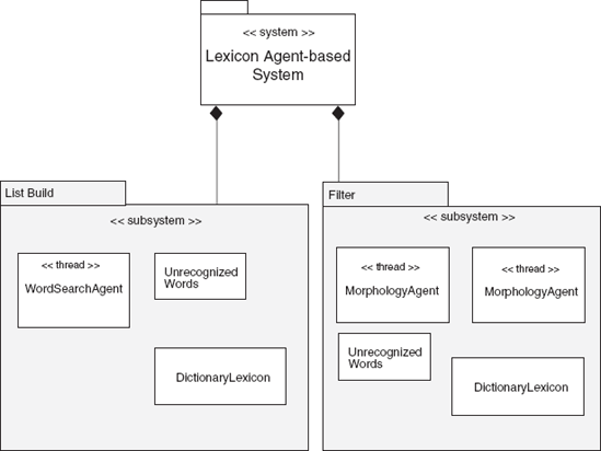
A system can be decomposed into subsystems and modules. The subsystems or modules will be further broken down into components, nodes, classes, objects, and interfaces. In the UML, subsystems or modules used at the architectural level of documentation are called packages. A package can be used to organize elements into a group that describes the general purpose of those elements. A package is represented as a rectangle with a tab on the upper-left corner. The package symbol contains the name of the package. The packages in the system can be connected by means of composition, aggregation, dependency, and association relationships. Stereotype indicators can be used to distinguish one type of package from another. Figure 9-20 shows the packages involved in the Lexicon system. The system package uses a <<system>> indicator to distinguish it from the List Build and Filter subsystems, which use the <<subsystem>> indicator. Because they are subsystems, they are related to the system by an aggregation relationship.
As we noted earlier, this chapter has covered some of the basic UML diagramming and notation techniques used to design and document the concurrent behavior in an application, but it is only an introduction to a very complex topic. We covered the following key points:
A model of a system is the body of information gathered for the purpose of studying the system. Documentation is a tool used in modeling a system. The UML, Unified Modeling Language, is a graphical notation used to design, visualize, model, and document the artifacts of a software system created by Grady Booch, James Rumbaugh, and Ivar Jacobson. It is the de facto standard for communicating and modeling object-oriented systems. The UML can be used to model concurrent from the structural and behavioral perspectives.
UML diagrams can be used to model to most basic units, the object, to the whole system. An object is the basic unit used in many UML diagrams. Dependency, inheritance, aggregation, and composition are some of the relationships that can exist between objects. Interaction diagrams are used to show the behavior of an object and identify concurrency in the system. Objects can interact with other objects by communicating and invoking methods. Collaborations diagrams depict the interactions between objects working together to perform some particular task. Sequence diagrams are used to represent the interactions between object in time sequence. Statecharts are used to depicts the actions of a single object over its lifetime.
When modeling the whole system, the basic unit is a package. A package can be used to represent systems and subsystems. Packages can have relationships with other packages such as composition or some type of association.
For a more comprehensive treatment on these techniques, we recommend the book Designing Concurrent, Distributed, and Real-Time Applications with UML by Hassan Gomaa (Addison-Wesley, 2000).
In the next chapter, we turn our attention to one last area of concern for multicore programming: testing and logical fault tolerance.