Chapter 8. Interrupts
And, as Miss [Florence] Nightingale was so vehemently to complain—“women never have an half hour... that they can call their own”—she was always interrupted.
In this chapter, we’ll take a look at interrupts—a sophisticated way of managing relationships with external devices. Interrupts are an important aspect of embedded software development and one that programmers need to study carefully in order to create efficient applications. The start of this chapter gives an introduction to interrupts and different characteristics associated with them. It is important to understand what happens when an interrupt event occurs and how the interrupt is processed. Although the implementation of interrupts is processor-specific, much of the material in this chapter applies to all processors. Finally, we will expand on the Blinking LED example by using an interrupt found in practically all processors.
Overview
An interrupt can be used to signal the processor for all sorts of events—for example, because data has arrived and can be read, a user flipped a switch, or a specific amount of time has elapsed.
Interrupts allow developers to separate time-critical operations from the main program to ensure they are processed in a prioritized manner. Because interrupts are asynchronous events, they can happen at any time during the main program’s execution.
Figure 8-1 shows two alternative wiring diagrams of peripherals connected to the processor interrupt pins.
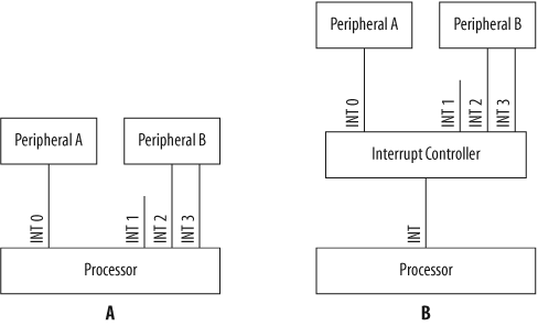
Figure 8-1(a) shows peripherals connected directly to the interrupt pins of the processor. In this case, the processor contains an interrupt controller on-chip to manage and process incoming interrupts. The PXA255 has an internal interrupt controller.
Figure 8-1(b) shows the two peripherals connected to an external interrupt controller device. An interrupt controller multiplexes several input interrupts into a single output interrupt. The controller also allows control over these individual input interrupts for disabling them, prioritizing them, and showing which are active.
Because many embedded processors contain peripherals on-chip, the interrupts from these peripherals are also routed to the interrupt controller within the main processor. Sometimes more interrupts are required in a system than there are interrupt pins in the processor. For these situations, peripherals can share an interrupt. The software must then determine which device caused the interrupt.
Interrupts can be either maskable or nonmaskable. Maskable interrupts can be disabled and enabled by software. Nonmaskable interrupts (NMI) are critical interrupts, such as a power failure or reset, that cannot be disabled by software.
A complete listing of the interrupts in your system can be constructed from information in the reference manuals for your processor and board. For example, the interrupts supported by the PXA255 processor are detailed in the PXA255 Processor Developer’s Manual. A partial list of the supported interrupts for the PXA255 is shown in Table 8-1. We will take a look at what the interrupt number means shortly.
| Interrupt number | Interrupt source |
| 8 | GPIO Pin 0 |
| 9 | GPIO Pin 1 |
| 11 | USB |
| 26 | Timer 0 |
| 27 | Timer 1 |
| 28 | Timer 2 |
Priorities
Because interrupts are asynchronous events, there must be a way for the processor to determine which interrupt to deal with first should multiple interrupts happen simultaneously. The processor defines an interrupt priority for all of the interrupts and exceptions it supports. The interrupt priorities are found in the processor’s documentation.
For example, the ARM processor supports six types of interrupts and exceptions. [1] The priorities of these interrupts and exceptions are shown in Table 8-2. This table is contained in the XScale Microarchitecture User’s Manual.
| Priority | Exception/interrupt source |
| 1 (highest) | Reset |
| 2 | Data abort |
| 3 | Fast Interrupt Request (FIQ) |
| 4 | Interrupt Request (IRQ) |
| 5 | Prefetch abort |
| 6 (lowest) | Undefined instruction or software interrupt |
Typically, when an interrupt occurs, a processor disables all interrupts at the same- or lower-priority levels. If multiple interrupts are waiting to be processed or are pending, the priority associated with the interrupts determines the order in which they are executed.
The method for handling interrupts at different priorities is very processor-specific. The following text describes some scenarios for handling interrupts at different priorities.
When a higher-priority interrupt occurs while a lower-priority interrupt is being processed, the processing of the lower-priority interrupt is suspended and the higher-priority interrupt is handled. Once the higher-priority interrupt completes, the processing of the lower-priority interrupt continues. This is called interrupt nesting.
If a lower-priority interrupt occurs while the processor is handling a higher-priority interrupt, the lower-priority interrupt is left pending until the higher-priority interrupt finishes executing.
When an interrupt occurs at the same priority as the interrupt currently being processed, the interrupt currently being processed is allowed to finish. Then the processing of the next interrupt starts. In this case, interrupt nesting can also occur if the currently executing interrupt reenables interrupts at its own priority level. In other words, an interrupt can allow itself to be interrupted by other interrupts that are at the same priority level.
Warning
Be careful when nesting interrupts. Additional forethought must go into the sizing of the stack, because each ISR that is interrupted must have its register state saved on the stack. This could lead to a stack overflow.
The interrupt priority is set by hardware design, by software, or, in some cases, by a combination of the two. If we look back at the wiring diagram in Figure 8-1(a), we see that the processor has four interrupt pins (INT0 through INT3). For this example, we’ll assume the processor gives INT0 the highest priority, followed by INT1, INT2, and INT3. The hardware designer must wire the interrupt pins so that the correct interrupt priorities are assigned to the various peripheral interrupts. In this case, the interrupt from Peripheral A has the highest priority.
Some interrupt controllers allow the priorities of interrupts to be set in software. In this case, the interrupt controller typically has registers that set the priorities of the various interrupts.
Levels and Edges
Level-sensitive interrupts cause the processor to respond as long as the interrupt signal is at the specified level. These interrupts are either high- or low-level-sensitive. Edge-sensitive interrupts cause the processor to respond when the interrupt signal goes through a transition. These interrupts are specified as rising or falling edge-sensitive. Figure 8-2 shows signals for a level-sensitive and edge-sensitive interrupt.

In Figure 8-2, the level-sensitive interrupt is active high. The time when the interrupt is active is shown in the signal diagram, which is the time when the signal is at the higher voltage. The interrupt signal on the bottom of Figure 8-2 is a rising edge-sensitive interrupt. It is active when the signal transitions from low to high, is held high for a certain minimum time (typically two or three processor clocks), and then it returns to low again.
There are issues related to both types of interrupts. For example, an edge-sensitive interrupt can be missed if a subsequent interrupt occurs before the initial interrupt is serviced. Conversely, a level-sensitive interrupt constantly interrupts the processor as long as the interrupt signal is asserted.
Most peripherals assert their interrupt until it is acknowledged. Some processors, such as the Intel386 EX, contain registers that can be programmed to support either level-sensitive or edge-sensitive interrupts on individual interrupts. Thus the sensitivity selection affects detection of new interrupts on that signal.
Acknowledging an interrupt tells the interrupting device that the processor has received the interrupt and queued it for processing. The method of acknowledging an interrupt can vary from reading an interrupt controller register to clearing an interrupt pending bit. Once the interrupt is acknowledged, the peripheral will deassert the interrupt signal. Some processors have an interrupt acknowledge signal that takes care of this automatically in hardware.
Enabling and Disabling
Maskable interrupts can be disabled and enabled either individually or globally. Nonmaskable interrupts, as the name implies, cannot be disabled. In the PXA255 processor, individual interrupts are masked in the Interrupt Controller Mask Register (ICMR). This register is shown in Figure 8-3.

The ICMR is located at address 0x40D00004. Figure 8-3 shows the Interrupt Mask (IM) for each of the interrupts supported in the PXA255. Setting the corresponding bit to 1 in the ICMR allows that particular source to generate interrupts; setting the corresponding bit to 0 masks that interrupt source.
For example, imagine that the interrupt pin from a peripheral is connected to GPIO pin 0 on the PXA255 processor. Table 8-1 shows that the GPIO pin 0 interrupt source is assigned to interrupt number 8. Therefore, to enable the GPIO pin 0 interrupt, bit 8 of the ICMR is set to 1. If an interrupt occurs when the GPIO pin 0 interrupt is enabled, it is routed to the interrupt controller for processing. To mask the GPIO pin 0 interrupt source, set bit 8 of the ICMR to 0. If an interrupt occurs while the source is disabled, the interrupt is ignored.
Each processor typically has a global interrupt enable/disable bit in one of its registers. The PXA255 has two bits in the Current Program Status Register (CPSR) that globally disable all interrupts.
Warning
It is important to remember to reenable interrupts in your software after you have disabled them. This is a common problem that can lead to unexplained behavior in the system. If interrupts are disabled at the entry to a function, ensure that all software paths that exit the routine reenable interrupts.
You generally cannot access the global interrupt flags directly
using the C language. In this case, you need to write assembly code to enable and disable global interrupts.
Some compiler libraries, such as those for the x86 family of
processors, contain functions to handle global interrupt enabling
(with the enable function) and
global interrupt disabling (with the disable function).
Interrupt Map
Now that we have an understanding of how an interrupt occurs, let’s take a look at how the processor goes about dealing with an interrupt in software. After the processor is reset, either by cycling power or asserting the reset signal, interrupts are disabled. One of the jobs of the startup code is to enable global interrupts once the system is ready for them. Part of the procedure for ensuring that the system is ready for interrupts is installing software to handle them. An interrupt service routine, which carries out the basic action necessary to deal with the interrupt, is associated with each interrupt.
In order for the processor to execute the correct ISR, a mapping must exist between interrupt sources and ISR functions. This mapping usually takes the form of an interrupt vector table. The vector table, located at a memory address known to the hardware, is usually an array of pointers to functions. The processor uses the interrupt number (a unique number associated with each interrupt) as its index into this array. In some processors, the value stored in the vector table array is usually the address of the ISR to be executed. Other processors actually have instructions stored in the array (commonly called a trampoline) to jump to the ISR.
For the ARM processor, the addresses in the interrupt vector table are at fixed locations in memory. These addresses are listed in Table 8-3.
| Exception/interrupt source | Address |
| Reset | 0x00000000 |
| Undefined instruction | 0x00000004 |
| Software interrupt | 0x00000008 |
| Prefetch abort | 0x0000000C |
| Data abort | 0x00000010 |
| IRQ | 0x00000018 |
| FIQ | 0x0000001C |
The addresses in Table 8-3 are locations in memory used by the ARM processor to execute the ISR for a particular interrupt. Information about the interrupt vector table is contained in the documentation about the processor. Because the addresses in the ARM interrupt vector table are 32 bits apart, the code installed in the interrupt vector table is a jump to the real ISR.
It is critical for the programmer to install an ISR for all interrupts, even the interrupts that are not used in the system. If an ISR is not installed for a particular interrupt and the interrupt occurs, the execution of the program can become undefined (commonly called “going off into the weeds”).
A good procedure is to install a default ISR in the interrupt vector table for any interrupt not used. The default ISR ensures that all interrupts are processed and acknowledged, allowing the main program to continue executing. Have your startup code initialize all interrupts in the vector table to the default handler to ensure there are no unhandled interrupts. Then install ISRs for specific interrupts used in the system.
The first part of initializing the interrupt vector table is to create an interrupt map that organizes the relevant information. An interrupt map is a table that contains a list of interrupt numbers and the devices to which they refer. This information should be included in the documentation provided with the board. A partial interrupt map for the Arcom board is shown in Table 8-4.
| Interrupt number | Interrupt source |
| 8 | Ethernet |
| 11 | USB |
| 21 | Serial Port 2 |
| 22 | Serial Port 1 |
| 26 | Timer 0 |
| 27 | Timer 1 |
| 28 | Timer 2 |
This table is similar to the interrupt list for the PXA255 processor shown in Table 8-1. However, this table shows the interrupt sources that are specific to the Arcom board.
Once again, our goal is to translate the information in the table
into a form that is useful for the programmer. The interrupt map table
should go into your project notebook for future reference. After
constructing an interrupt map such as the one in Table 8-4, you should add
a third section to the board-specific header file. Each line of the
interrupt map becomes a single #define within the file, as shown here:
/**********************************************************************
 *  Interrupt Map
 **********************************************************************/

#define ETHERNET_INT                (8)
#define USB_INT                     (11)
#define SERIAL2_INT                 (21)
#define SERIAL1_INT                 (22)
#define TIMER0_INT                  (26)
#define TIMER1_INT                  (27)
#define TIMER2_INT                  (28)
Interrupt Service Routine
Let’s take a closer look at the ISR. The ISR is the function called when a particular interrupt occurs. Its central purpose is to process the interrupt and then return control to the main program. Typically, ISR functions have no arguments passed into them; they can never return a value.
In order to keep the impact of interrupts on the execution of the main program to a minimum, it is important to keep interrupt routines short. If additional processing is necessary for a particular interrupt, it is better to do this outside of the ISR. Keeping ISRs short also aids in ISR debug, which can be difficult. When it is done by a specific function, completion of the interrupt handling outside the ISR is called a deferred service routine (DSR).
Regardless of the specific processing required by the ISR, the ISR is responsible for doing the following things:
- Saving the processor context
Because the ISR and main program use the same processor registers, it is the responsibility of the ISR to save the processor’s registers before beginning any processing of the interrupt. The processor context consists of the instruction pointer, registers, and any flags. Some processors perform this step automatically.
- Acknowledging the interrupt
The ISR must clear the existing interrupt, which is done either in the peripheral that generated the interrupt, in the interrupt controller, or both.
- Restoring the processor context
After interrupt processing, in order to resume the main program, the values that were saved prior to the ISR execution must be restored. Some processors perform this step automatically.
Some compilers include the keyword
interrupt or something similar. This enables the
compiler to automatically generate the code used to save the context
when the ISR is entered, and to restore the context when the ISR is
exited. An example of code that includes the interrupt keyword follows:
interrupt void interruptServiceRoutine(void)
{
    /* Process the interrupt. */
}
The documentation for the compiler shows whether the interrupt keyword is supported. If the
compiler does not support this keyword, a compiler-specific #pragma may be required to declare an ISR. The
GNU compiler gcc uses a third
approach, involving the compiler-specific keyword __attribute__, which takes options as
arguments, as shown here:
void interruptServiceRoutine() __attribute__ ((interrupt ("IRQ")));Some processors, such as certain Microchip PICs, can have only one ISR for all interrupts. This ISR must determine the source of the interrupt by checking each potential interrupt source. In this case, it is a good idea to check the most important interrupt first. The technique used by the ISR to determine that the interrupt source is hardware-specific.
Tip
When designing your software, it is typically best to include the ISR for a particular device in the driver for that peripheral. This keeps all the device-specific code for a particular peripheral isolated in a single module.
Figure 8-4 is a graphical representation of the interrupt process. For this example, we will assume the Ethernet network interface controller generates the interrupt, although this process is relevant for any interrupt.

In Figure 8-4, the processor is executing the main program when an interrupt occurs from the Ethernet network interface controller. The processor finishes the instruction in progress before halting execution of the main program. (Some processors allow interruption of long instructions so that interrupts are not delayed for extended periods of time.)
The processor next looks up the address of the ISR for the
Ethernet network interface controller, interruptEthernetISR, in the interrupt vector
table, and the processor jumps to this function. The interruptEthernetISR function saves the
processor context to the processor’s stack.
The ISR then clears the interrupt. Once complete, the ISR restores the context and returns. The main program continues its execution from the point at which it was interrupted. Most processors have a special “return from interrupt” instruction for exiting the ISR.
One important concept associated with interrupts is latency. Interrupt latency is the amount of time from when an interrupt occurs to when the processor begins executing the associated interrupt service routine. Interrupt latency is a metric used by some engineers to evaluate processors and is very important in real-time systems. Disabling interrupts increases interrupt latency in an embedded system, because the latency includes the time between the occurrence of the interrupt and the moment interrupts are reenabled.
Although there is a single ISR for each interrupt, there might be a number of reasons the interrupt occurs. It is the responsibility of the ISR to determine the specific cause of the interrupt and proceed accordingly. The following code framework shows how an ISR reads the interrupt status register to determine the interrupt, acknowledges the interrupt by writing the value back to the interrupt status register, and then determines the cause of the interrupt. It is quite possible that more than one interrupt source is active during the ISR. Thus, the ISR must check every source; failure to do so may result in missing an interrupt.
interrupt void interruptServiceRoutine(void)
{
    uint8_t intStatus;

    /* Determine which interrupts have occurred. */
    intStatus = *pIntStatusReg;

    /* Acknowledge the interrupt. */
    *pIntStatusReg = intStatus;

    if (intStatus & INTERRUPT_SOURCE_1)
    {
        /* Do interrupt processing. */
    }

    if (intStatus & INTERRUPT_SOURCE_2)
    {
        /* Do interrupt processing. */
    }
}
Shared Data and Race Conditions
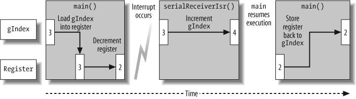
A common issue when designing software that uses interrupts is how to share data between the ISR and the main program. A race condition is a situation where the outcome varies depending on the precise order in which the instructions of the main code and the ISR are executed; this should be strenuously avoided.
It can be extremely difficult to find race condition bugs because interrupts are asynchronous events and, to make matters worse, the race condition doesn’t occur every time the code executes. Your software can run for days and pass all production tests without exhibiting this bug—but then, once the unit is shipped to the customer, it is certain to show up.
The following code example will give you a better understanding
of race conditions. Imagine that the serial port ISR serialReceiveIsr is invoked when an incoming
character arrives. As characters are received, gIndex is incremented to keep track of the
number of characters stored in the memory buffer.
The main function also uses
gIndex, by decrementing it when it
processes the received characters in the memory buffer. Here is the
example code:
int gIndex = 0;

interrupt void serialReceiveIsr(void)
{
    /* Store receive character in memory buffer. */

    gIndex++;
}

int main(void)
{
    while (1)
    {
        if (gIndex)
        {
            /* Process receive character in memory buffer. */

            gIndex--;
        }
    }
}
Can you spot the problem with this code?
Let’s assume the variable gIndex has a value of 3 when the line of
code that decrements this variable executes:
gIndex--;
This line of code results in assembly-language instructions that do something like this:
            LOAD gIndex into a register;
            DECREMENT the register value;
            STORE the register value back into gIndex;
The first step is to read the value of gIndex, 3, from its location in RAM into a
processor register. Next, the register value is decremented, resulting
in a value of 2.
Now suppose a serial port receive interrupt occurs before the
new value of gIndex is stored in
the memory. The processor stops executing main and executes the serial port ISR,
serialReceiveIsr. The ISR
increments gIndex to a value of
4.
The processor resumes execution of main after the ISR exits. At this point,
main executes the line of code that
stores the register value, 2, back into the variable gIndex. Now gIndex has a value of 2, as if the latest
interrupt never occurred to increment gIndex.
This race condition can cause the program to lose incoming characters. Figure 8-5 shows the race condition for this example code.
The decrement code in the main program is called a
critical section. A critical section is a
part of a program that must be executed in order and
atomically, or without interruption. A line
of C code (even as trivial as increment or decrement) is not
necessarily atomic, as we’ve seen in this example.
So, how is this problem corrected? Because an interrupt can occur at any time, the only way to make such a guarantee is to disable interrupts during the critical section. In order to protect the critical section in the previous example code, interrupts are disabled before the critical section executes and then enabled after, as shown here:
int main(void)
{
    while (1)
    {
        interruptDisable();

        if (gIndex)
        {
            /* Process receive character in memory buffer. */

            gIndex--;
        }

        interruptEnable();
    }
}
In embedded systems, and especially real-time systems, it is important to keep interrupts enabled as much as possible to avoid hindering the responsiveness of the system. Try to minimize the number of critical sections and the length of critical section code.
Tip
The safest solution is to save the state of the interrupt enable flag, disable interrupts, execute the critical section, and then restore the state of the interrupt enable flag. Enabling interrupts at the end without ensuring that they were enabled at the outset of the critical section is risky.
Race conditions can also occur when the resource shared between an ISR and the main program is a peripheral or one of the peripheral’s registers. For example, suppose a main program and an ISR use the same peripheral register. The main program reads a register and stores the value. At this point, an ISR executes and modifies the value in that same register. When the main program resumes and updates the peripheral register, the ISR’s value is overwritten and lost.
Critical sections are also an issue when using a real-time operating system (RTOS), because the tasks may then also share resources such as global variables or peripheral registers. We will look at this in Chapter 10.
The Improved Blinking LED Program
Now we will look at an interrupt example using a timer. For this example, we will use the Blinking LED code from Chapter 3. However, instead of using a loop to handle the timing of the LED blink, we will use a hardware timer. Most microcontrollers include up to several timers.
There are several advantages to using a timer rather than a loop
for the timing: the processor is free to handle other tasks instead of
sitting in a while loop doing
nothing, a timer is more accurate for measuring a loop than a stopwatch,
and you can calculate the exact time you want the timer interrupt to
fire instead of using a trial-and-error approach based on the
processor’s clock.
In this improved Blinking LED program, the delay routine is eliminated and a timer device driver is used to handle the delay between LED toggles. The timer is used to interrupt the processor once a specific interval has elapsed.
How Timers Work
A timer is a peripheral that measures elapsed time, typically by counting down processor cycles or clocks. A counter, by contrast, measures elapsed time using external events. A timer is set up by programming an interval register in the timer peripheral, with a specific value calculated by the software engineer to determine the timer interrupt interval. The timer peripheral then uses a clock to keep count of the number of ticks that have elapsed since the timer has been started. The number of clock ticks is compared to the value in the timer interval register. Once they are equal, a timer interrupt is generated (if enabled).
The timer counts cycles either from the processor’s main clock signal or from a separate clock fed into the timer peripheral from an external processor pin. In some processors, the clock used for the timer can be selected by programming the timer’s configuration registers. Many processors today also include multiple internal clock sources that can be used to drive the timers.
On some processors, the calculated time interval is programmed into a timer register that is itself decremented at each clock tick. Once the value in that register hits zero, a timer interrupt is generated. The timer peripheral then reloads the timer register with the calculated interval value (stored in a separate register) and once again begins decrementing this value at each clock tick. Other processors, such as the PXA255, have timers that count up. Be sure to check your processor’s documentation to understand how your timer functions.
The PXA255 processor has four timers. For this example, timer 0 is used; the 32-bit PXA255 timer registers for timer 0 are shown in Figure 8-6.
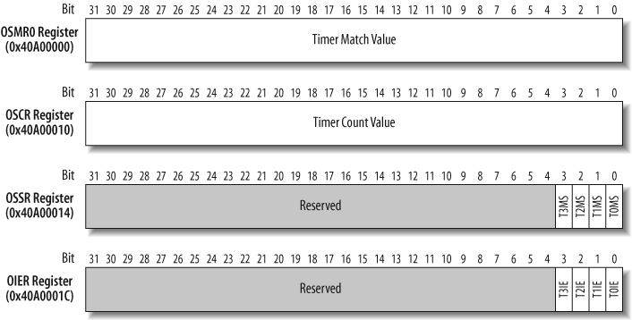
On the PXA255, the timer count register (OSCR) contains a count that is incremented on rising edges of the timer clock, which operates at 3.6864 MHz. In other words, each time the clock signal goes from low to high, the OSCR is incremented by one.
The timer match register (OSMRn, where n is the timer number) contains the timer values for the four different timers. After every rising edge of the timer clock, the processor compares the value in the OSMRn to the OSCR. If there is a match, an interrupt is generated and the corresponding bit is set in the timer status register (OSSR). The timer interrupt enable register (OIER) determines which interrupts are enabled for the four different timers.
The main routine for the Blinking LED
implementation that uses a timer instead of a delay loop is very
similar to the main routine
discussed in Chapter
3. This part of the code is hardware-independent. The main function starts with initialization of
the LED control port with the ledInit function. An initialization routine
for the timer device driver, timerInit, is called to initialize and start
the timer hardware.
The infinite loop in main is
empty in this case because there is no other processing needed for
this version of the Blinking LED program. All of the processing
happens in the background with the timer interrupt, but the infinite
loop is still needed in order to keep the program running. Notice here
that the delay_ms function has been
removed:
#include "led.h"
#include "timer.h"

/**********************************************************************
 *
 * Function:    main
 *
 * Description: Blink the green LED once a second.
 *
 * Notes:
 *
 * Returns:     This routine contains an infinite loop.
 *
 **********************************************************************/
int main(void)
{
    /* Configure the green LED control pin. */
    ledInit();

    /* Configure and start the timer. */
    timerInit();

    while (1)
        ;

    return 0;
}
The timerInit routine
initializes the registers needed for the timer device driver and then
enables the timer interrupt. The global state variable bInitialized is used to ensure the timer
registers are only configured once.
The first step to configure the timer is to clear any pending interrupts. This is done
by writing bit 0 (defined by the bitmask TIMER_0_MATCH) to the timer status (OSSR)
register (defined by the macro TIMER_STATUS_REG).
For the next step, we need to calculate the interrupt interval. The PXA255 Processor Developer’s Manual states that the timers are incremented by a 3.6864 MHz clock. To toggle the LED every 500 ms, the following equation is used to determine the value for the timer match register:
| Timer Match Register Value = Timer clock × Timer interval |
For our example, the calculation is:
| Timer Match Register Value = 3,686,400 Hz × 0.5 seconds |
| = 1,843,200 |
| = 0x001C2000 |
The macro TIMER_INTERVAL_500MS is set to the interval
value 0x001C2000. The PXA255 Processor Developer’s
Manual describes the algorithm for setting up a timer as
follows:
Read the current count value in the timer count register (OSCR).
Add the interval offset to the current count value. This value corresponds to the amount of time before the next time-out.
Program the new interval value into the timer match register (OSMR0).
To set the timer interval, the OSMR0 register (defined by the
macro TIMER_0_MATCH_REG) is
programmed with the current value of the timer count plus the TIMER_INTERVAL_500MS timer interval.
Next, the timer interrupt is enabled in two places: the timer
peripheral and the interrupt controller. In the timer peripheral, the timer
interrupt enable is controlled by bit 0 (defined by the bitmask
TIMER_O_INTEN) in the 32-bit OIER
(defined by the macro TIMER_INT_ENABLE_REG).
Then the interrupt controller is configured to allow interrupts
from the timer peripheral. As shown in Table 8-4, the timer 0
interrupt is mapped to interrupt number 26. Therefore, the program
sets bit number 26 (defined by the macro TIMER_0_ENABLE) in the Interrupt Controller Mask Register (ICMR) (defined by
the macro INTERRUPT_ENABLE_REG).
Warning
Because the timerInit
function enables the timer 0 interrupt in the interrupt controller,
an ISR for the timer 0 interrupt must be installed prior to calling
this routine.
For the final step, initializing the timer, set the
initialization state variable to TRUE, as shown here:
#define TIMER_INTERVAL_500MS        (0x001C2000)

/**********************************************************************
 *
 * Function:    timerInit
 *
 * Description: Initialize and start the timer.
 *
 * Notes:       This function is specific to the Arcom board.
 *              Ensure an ISR has been installed for the timer prior
 *              to calling this routine.
 *
 * Returns:     None.
 *
 **********************************************************************/
void timerInit(void)
{
    static int bInitialized = FALSE;

    /* Initialize the timer only once. */
    if (bInitialized == FALSE)
    {
        /* Acknowledge any outstanding timer interrupts. */
        TIMER_STATUS_REG = TIMER_0_MATCH;

        /* Initialize the timer interval. */
        TIMER_0_MATCH_REG = (TIMER_COUNT_REG + TIMER_INTERVAL_500MS);

        /* Enable the timer interrupt in the timer peripheral. */
        TIMER_INT_ENABLE_REG |= TIMER_0_INTEN;

        /* Enable the timer interrupt in the interrupt controller. */
        INTERRUPT_ENABLE_REG |= TIMER_0_ENABLE;

        bInitialized = TRUE;
    }
}
Prior to entering the ISR, the processor context is saved. Use the following function declaration so that the GNU compiler includes the code for the context save (and restore at the end of the ISR):
void timerInterrupt() __attribute__ ((interrupt ("IRQ")));Next, the ISR acknowledges the timer 0 interrupt. The processor
documentation states that acknowledging a timer interrupt is
accomplished by writing a 1 to the timer 0 bit (defined by the bitmask
TIMER_0_MATCH) of the 32-bit OSSR
(defined by the macro TIMER_STATUS). See Figure 8-6 for
details of the OSSR and timer 0 match status bit 0 (T0MS).
Next, the LED state changes with a call to the function ledToggle. Then the timer match value is
updated for the next timer interrupt interval. To update the timer 0
match register, first read the current timer count, add the timer
interval, and then write this result into the timer match register
(TIMER_0_MATCH_REG).
Finally, the processor context is restored and the ISR returns:
#include "led.h"

/**********************************************************************
 *
 * Function:    timerInterrupt
 *
 * Description: Timer 0 interrupt service routine.
 *
 * Notes:       This function is specific to the Arcom board.
 *
 * Returns:     None.
 *
 **********************************************************************/
void timerInterrupt(void)
{
    /* Acknowledge the timer 0 interrupt. */
    TIMER_STATUS = TIMER_0_MATCH;

    /* Change the state of the green LED. */
    ledToggle();

    /* Set the new timer interval. */
    TIMER_0_MATCH_REG = (TIMER_COUNT_REG + TIMER_INTERVAL_500MS);
}
You can now build this code and run it on the target Arcom board. If successfully built, this version of the Blinking LED program should operate the same way as the one shown in Chapter 3.
Summary of Interrupt Issues
Interrupts are an important part of most embedded systems. Here are some key points to keep in mind when dealing with interrupts:
- Get the first interrupt
Focus on getting the specific interrupt you are working on to occur first. Then move on to getting that interrupt to fire subsequent times.
- Interrupt blocked
Interrupts can be blocked at several points. Ensure that the specific interrupt is enabled both in the interrupt controller and at the source peripheral device. Make sure that global interrupts are enabled in the processor.
- ISR installation
Verify that the ISR is installed in the interrupt vector table properly and for the correct interrupt vector. Understand the mapping of interrupts for the processor. Using the LED debug technique mentioned in Chapter 5 can be a valuable tool for tracing the execution path when an interrupt occurs.
- Protect against unhandled interrupts
Ensure that there is an ISR for every interrupt in the system. It is best to install a default ISR for all interrupts at initialization time to ensure every interrupt is handled.
- Processor context
Make sure the processor context is saved and restored properly in the ISR. Registers can be trampled by an ISR that will eventually wreak havoc on your main program.
- Acknowledge the interrupt
The interrupt must be acknowledged so that the signal is deasserted. If this is done incorrectly or not done at all, ISRs for the same or lower-priority interrupts won’t run again. Or, if it is a level-sensitive interrupt, the ISR will run repeatedly because the interrupt signal will remain asserted.
- Avoid race conditions
A lot of forethought must go into designing your software if the embedded system you are working on uses interrupts. The communication mechanisms between the main program and the interrupt service routines must be carefully thought out. Race conditions are dangerous errors that can be extremely difficult to find.
- Enabling and disabling
Keep disabling of interrupts to a minimum to reduce interrupt latency; this is very important in real-time systems. Be careful in the implementation of the disable and enable code around critical sections. Always use a variable to keep track of the enable state of interrupts so that interrupts are properly restored, and to avoid potential interrupt problems.