
Chapter 8
3D Graphics Fundamentals
This chapter provides a quick introduction to 3D graphics, which you will use to develop 3D apps in Windows Mixed Reality. It omits mathematical details and instead focuses on providing general definitions of terms that will be used throughout Chapters 9 through 15. The chapter starts by defining coordinate systems used to represent pixels and voxels. It then describes vertices, primitives, and polygons, followed by transformations, quaternions and rotations, shaders and lighting, textures and materials, and particle systems. The chapter ends with a brief glossary of terms.
Pixels, Voxels, and Coordinate Systems
A pixel is an individual point in an image displayed on a screen. The position of the pixel is identified by coordinates in a two-dimensional (2D) Cartesian coordinate system. (See the left image in Figure 8-1.) A Cartesian coordinate system has two perpendicular axes (x and y), along which a pixel can be positioned. In such a system (which is employed by Unity), x values increase from right to left, and y values increase from bottom to top, with the origin of the coordinate system in the bottom-left corner of the screen. However, most 2D graphics computer software sets the origin in the top-right corner of the bitmap or screen, with x values increasing from left to right and y values increasing from top to bottom. This type of coordinate system is typically referred to as a computer coordinate system.
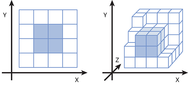
In 3D graphics, pixels are generalized to voxels, which represent individual points in the 3D space. Think of a voxel as a small cube within a larger one, as in the right image in Figure 8-1. Consequently, each voxel is represented using three coordinates (x, y, z) in a 3D Cartesian coordinate system. Again, the x and y values increase from left to right and from bottom to top, respectively. The z axis, however, can be oriented in two possible ways: pointing into the screen or out of it. In the first case, which is defined as a right-handed coordinate system, z values increase as they move toward you (assuming you are sitting in front of the screen). In the second case, called a left-handed coordinate system, z values increase as they move away from you.
3D graphics use several types of coordinate systems, among which the following five are most important:
- World coordinate system This is a reference coordinate system along which all other systems, and consequently all objects (or models), are positioned within the scene. This system is sometimes called a model or universe coordinate system, or, as in Windows Mixed Reality, a spatial coordinate system, as it is used to determine positions of both virtual and real objects.
- Object coordinate system This type of coordinate system is typically associated with individual objects. Its origin is anchored to a specific voxel of a 3D object.
- Viewpoint or camera coordinate system The origin of this type of coordinate system is tied to the observer’s or camera’s position. This coordinate system translates as the user moves around the scene.
- Screen coordinate system This 2D coordinate system represents pixels on the screen. The extent of this system is determined by the display’s resolution.
- Viewport coordinate system This is a 2D subset of the screen coordinate system used to represent images displayed within a single window or part of the screen.
Pixels and voxels are represented in computer memory as arrays of integers or floating numbers. Specifically, a pixel in a 2D screen coordinate system is represented by two numbers, while a voxel is represented by three numbers. In general, the location of an individual pixel or voxel can be described with integral vertices due to finite resolutions. However, points of a line connecting two pixels or voxels require floating-point numbers.
Vertices, Primitives, and Polygons
A vertex is a common endpoint of rays or lines, while a primitive is a figure composed of connected vertices. These vertices can be connected in various ways. The simplest primitive is a line segment, which connects two vertices with a straight line. To represent curves, line segments are divided into smaller segments that are connected at different angles to smoothly approximate the curve. The more of these smaller segments, the better curve approximation.
When line segments are connected in such a way as to form a closed loop, the resulting figure is a polygon. Polygons serve as the building blocks for polygonal meshes that represent the shape of a complex object. Polygons approximate shapes in much the same way line segments approximate curves; the smaller the polygon, the better approximation of a specific surface. In Chapter 12, you will see that the HoloLens uses this type of polygon approximation to represent real objects in the user’s environment.
Viewing
Viewing is the process of preparing a 3D scene to be displayed or rendered on a 2D screen such that all objects will appear naturally, much as photography converts a 3D scene to a 2D picture. Even though the images are 2D, we can still determine that some objects are closer than others, and even recognize that they were originally 3D.
The quality of a photo (and hence the viewing process) depends on multiple factors, including your position and lighting conditions. To capture a good image, you first position your camera—in other words, you establish the viewing position within the world coordinate system. Then, you configure your flash, or lighting, adapt the zoom, and focus (optically or digitally, depending on the camera’s capabilities). In this way you set the size and sharpness of the objects in the final image. The lens acts as a projector, projecting the 3D scene to a 2D image, which is represented in the screen coordinate system. You then capture the image and eventually crop it to contain only the portion of the image you want to see. This is your viewport transformation.
A similar approach is used in 3D graphics, but here, everything (including light) is computer-generated. Specific algorithms (like ray tracing) use a model of a light source to analyze the propagation of light rays reflected from scene objects. This is used to determine which rays can be seen by the observer and thus which objects should be displayed within the viewport. There are several transformations involved during the viewing process:
- The vertices are transformed by a viewing transformation, which depends on the observer’s position and field of view, and on light conditions.
- The vertices are projected by a perspective transformation onto a 2D screen and eventually cropped if only a portion of the screen displays the scene.
After all the transformations are applied, the models are rendered such that the polygons approximating the surface are drawn using textures and shaders. The following sections discuss these transformations and renderings in more detail.
Transformations
Examples of transformations include changes to a model’s position, rotation, and scale. These are represented by the transformation matrix (T). Because vertices can be arranged into vectors (v), the process of transforming models can be performed with the matrix multiplication (Tv). This multiplication can be easily implemented in the 3D modeling and rendering software, including various engines for 3D game and app programming.
Generally, you do not need to manually modify each entry of the transformation matrix. Instead you specify the translation, rotation, and scale along each direction. The engine uses these values to construct the T matrix and perform all calculations accordingly. In practice, this means that when you change the x value of the translation by, say, 20 pixels, the model will move accordingly in the scene preview.
Matrices are used not only to represent model transformations, but also to represent projection transformations. These transformations are responsible for projecting the 3D model onto the 2D screen. There are two common projection transformations:
- Perspective projection This causes objects that are farther from the observer to appear smaller on the screen.
- Orthographic projection This does not change the relative size of objects.
![]() Note
Note
In next chapter, you will see that you can use Unity Editor to quickly switch between perspective and orthographic projections to preview the scene under different conditions.
Quaternions and Rotations
Quaternions are commonly used in 3D graphics to represent rotations. They are represented as a 4x4 matrices used to derive the rotation matrix (R). This can be merged with other transformations (like translation or scale) by matrix multiplication, leading to the affine transform. This transformation is a composition of translation, rotation, scale, and shear.
In Unity and UrhoSharp you need not directly set particular entries for quaternions or rotation matrices. Instead, you use the editor to manipulate rotation angles along each direction or use appropriate methods from the programming interface that will instantiate the rotation matrix for you. Later chapters contain specific instructions for rotating models using Unity Editor, C# Unity scripts, and the C# API of UrhoSharp.
Shaders and Lighting
Picture quality depends strongly on lighting conditions. Objects look different when they are backlit than they do in direct light. Indeed, many photographers use light to alter the final appearance of an object and to control the shade in an image. Typically, light affects not only the object’s brightness in the image but also the viewer’s 3D perception.
To emulate various lighting conditions, computer graphics software uses shaders. Shaders control the brightness and color of individual pixels composing the surface of the model. For example, to render a 3D cube, the computer software applies different shades of a specific color to each side of the cube.
![]() Note
Note
One of the first realistic shading models was developed in 1973 by Bui Toung Phong. His model, known as Phong interpolation, is used in 3D graphics to realistically approximate the shading of smooth surfaces.
In practice, a shader is a piece of code that dynamically calculates the color that should be applied to a pixel during rendering. As in classical photography, shading 3D graphics depends strongly on the lighting conditions. Such effects are emulated in 3D graphics using various lighting models. Shaders use these models along with material configurations (see the next section) to determine what color should be used to display a pixel on the screen.
There are several types of light. These include the following:
- Point light This type of light originates from a point-like source and emerges in all directions.
- Spot light This is like a point light in that it originates from a point, but it emerges in a cone shape rather than in all directions.
- Directional light This type of light illuminates all objects equally from a specific direction, much like the sun. Directional light is automatically added to all scenes in Unity.
- Ambient light This type of light is emitted in all directions and affects all objects in the scene in the same way. In other words, when the intensity of the ambient light changes, the brightness of all objects will change accordingly.
![]() Note
Note
For more on these various types of light, all of which are used by Unity, see http://bit.ly/light_types.
Unity and UrhoSharp contain several built-in shaders that are usually sufficient for app development, meaning you need not have a detailed knowledge of the mathematics behind them. You will apply shaders to models and eventually control their parameters in upcoming chapters. However, this book does not cover creating custom shaders manually or programmatically.
Textures and Materials
A texture is a 2D image applied to a surface before shading. Typically, textures are used to render relatively large surfaces. For example, without textures, rendering a tree would mean drawing thousands of small surfaces on a tree-shaped object, each containing a specific number of pixels of a uniform color. Textures enable you to approximate the tree by creating a larger and simpler two-dimensional surface and applying it to a tree-shaped object.
In practice, textures are made of bitmap images, so they can be easily ported between various apps. The process of applying a texture to a surface is called texture mapping. In this process, a two-dimensional texture is wrapped around an object to precisely match its shape and orientation in the 3D space.
In Unity and UrhoSharp, you do not explicitly control texture mapping. Rather, you apply textures through a material. You then associate the material with the model to perform the rendering. This means the model cannot be rendered without a material. Hence, in Unity, primitive 3D models are automatically associated with a default material when you add them to the scene. The material includes not only a reference to the texture but also all the information required to render the surface, including shader configuration. In this part of the book, you will use materials to format 3D objects, which will act as holograms in your Windows Mixed Reality apps.
Particle Systems
So far, the 3D graphics concepts discussed in this chapter have pertained to static objects that do not move during runtime. This is in contrast to dynamic objects, whose motion depends on size, external forces, and possible interactions, such as collisions, with other objects.
Mathematically modeling the movements of large individual objects can be done relatively easily. However, modeling the movement of many small particles composing an atmosphere or fluid is a real challenge. To approximate the dynamics of such objects, 3D graphics software uses particle systems. A particle system is a group of small simple images or meshes (particles) that move collectively to create the impression that they constitute a complete system.
Particle systems are typically defined by two parameters:
- Emission This refers to when a given particle was generated.
- Lifetime This refers to how long the particle will be present in the system and thus visible in the scene.
Each emitted particle has an associated velocity vector that specifies where and how quickly the particle is moving. This vector may be affected by gravity, obstacles, or wind. Gravity attracts a particle to the ground, while obstacles and wind change the direction of the particle’s motion. In Chapter 10 you will learn how to use particle systems to create reliable explosion effects.
Glossary of Terms
For your reference, here is a glossary of the most important terms to remember from this chapter:
Line segment A straight line that connects two vertices.
Material A full rendering definition including shader and textures information.
Mesh A collection of vertices that define the shape of a 3D object.
Model A representation of a 3D object based on the mesh. The model extends the mesh by a material and, eventually, animations.
Pixel A single point in a 2D image or on a screen.
Polygon A figure made of line segments.
Primitive A figure formed by connected vertices.
Shader An algorithm that defines how to render the pixels of a surfaces.
Texture A two-dimensional array of data that can be applied to surfaces before shading.
Vertex A common endpoint of lines. Vertices are fundamental elements that compose primitives in 3D graphics.
Voxel A single point in a 3D scene.
Summary
This chapter provided a brief and concise introduction to 3D computer graphics concepts that will be used in Chapters 9 through 15 to develop 3D apps for Windows Mixed Reality. The chapter omits full mathematical descriptions because this book does not cover the creation of models or shaders from scratch. Rather, to control the scene, you will use predefined objects, shaders, materials, and various Unity or UrhoSharp components.