Chapter 15
UrhoSharp
UrhoSharp is the cross-platform .NET binding to the C++ Urho3D game engine. It provides a powerful 3D rendering engine that is useful for Mixed Reality development, including physics simulations, scene handling, navigation, networking, and more. Importantly, you can access all this directly through the C# code. Unlike with Unity, which you used in Chapters 9 through 14, you will now build your app directly from the code. This allows you to implement the whole scene and related logic in a separate .NET library, which you can later reuse on other projects. These projects can target not only the Windows Mixed Reality platform but also iOS, Android, and Mac.
You can add UrhoSharp to your project as a NuGet package. There is one main package, UrhoSharp, and a number of platform-specific extensions. In this chapter you will learn how to use the UrhoSharp.SharpReality extension, which targets HoloLens. After you set up a project and create a hologram, you’ll explore several features of this package in this chapter, including physics simulations and spatial mapping. You’ll also explore HoloLens-specific features (called SharpReality).
![]() Note
Note
Everything in this chapter will be built using Visual Studio 2017 without Unity.
Setting Up the Project
You can build your Mixed Reality app that uses UrhoSharp on top of the Universal Windows Platform Visual C# project. You have already used this kind of project template in this book. By default, the Blank App UWP project comes with elements that handle app activation (App.xaml) and implement the default view (MainPage.xaml). Additionally, when you build the app, the entry point (the static Main method of the Program class) is automatically generated. (You can check this by inspecting the App.g.i.cs file located in the Obj subfolder of the Output directory.) For MR applications, the UrhoSharp engine can run in its own view source, which does not require any of the default elements included in the Blank UWP project template (App.xaml and MainPage.xaml). Also, UrhoSharp should be instantiated within the entry point.
To create the UrhoSharp MR app, start by creating the UWP project template you used previously to create 2D apps. Proceed as follows:
- In Visual Studio, open the File menu and choose New Project to open the Add New Project dialog box.
- In the Add New Project dialog box, type Blank App Visual C# in the search box.
- Select the Blank App (Universal Windows) Visual C# template in the search results.
- Type ExploringUrhoSharp in the Name field and click OK. (See Figure 15-1.)

FIGURE 15-1 Creating the blank UWP app. - In the New Universal Windows Platform Project dialog box (see Figure 15-2), open the Target Version drop-down list and choose Windows 10 Creators Update (10.0; Build 15063). Then open the Minimum Version drop-down list and choose Windows 10 November Update (10.0; Build 10586), and click OK.

FIGURE 15-2 Configuring target and minimum versions. - In Solution Explorer, right-click App.xaml and choose Delete from the menu that appears. Then click OK in any dialog box that appears.
- Repeat step 6 for MainPage.xaml.
- To install and set up UrhoSharp, open the Tools menu, choose NuGet Packet Manager, and select Package Manager Console to open the NuGet Package Manager Console. Then type the following command:
Install-Package UrhoSharp.SharpReality -ProjectName ExploringUrhoSharp
The last argument of this command (
ProjectName) is optional. It specifies the project in which UrhoSharp should be installed. This is especially useful when you install NuGet packages in solutions composed of many projects.After the package is installed, the Package Manager Console should display the following confirmation:
Successfully installed 'UrhoSharp.SharpReality 1.8.93' to ExploringUrhoSharp
Executing nuget actions took 1.24 sec
Time Elapsed: 00:00:03.3766804Subsequently, you can proceed to the actual implementation, which proceeds as follows:
- In Solution Explorer, right-click the ExploringUrhoSharp project, select Add, and choose Class. The Add New Item – ExploringUrhoSharp dialog box opens.
- Ensure the Class Visual C# item is selected. Then type Program.cs in the Name box and click OK to add the Program.cs file to the project.
- Modify the contents of the Program.cs file as shown in Listing 15-1.
LISTING 15-1 A custom app entry point that launches the UrhoSharp view source
using System;using Urho;
using Windows.ApplicationModel.Core;
namespace ExploringUrhoSharp
{
public static class Program
{
[MTAThread]
static void Main() => CoreApplication.Run(
new UrhoAppViewSource<MixedRealityApplication>());
}
} - Visual Studio displays a message indicating that it cannot resolve the MixedRealityApplication class. To create the class in a separate file, click the yellow light bulb icon next to the message, select Generate Type ‘MixedRealityApplication’, and choose Generate Class ‘MixedRealityApplication’ in New File. (See Figure 15-3.) The ExploringUrhoSharp project will now include a new MixedRealityApplication.cs file.
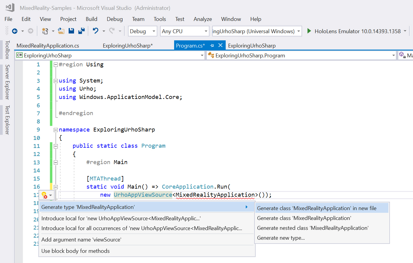
FIGURE 15-3 Creating a definition of the missing class.
Before we proceed, let’s discuss the code from Listing 15-1. This code implements the app entry point—the static Program.Main method from which the app will start its execution. The Main method invokes a single statement, which runs the application. Thus, the Main method is defined using an expression body in which the method definition starts after the => operator. As shown in Listing 15-1, to start the 3D engine from UrhoSharp you use the Run method of the CoreApplication class. This method, defined under the Windows.ApplicationModel.Core namespace, provides the basic functionality for each UWP app for handling state changes and managing windows. An instance of the CoreApplication class is created by the operating system when it runs the app. There is only one instance of CoreApplication per application. Moreover, the CoreApplication requires threads created from it to be decorated with the MTAThread attribute. Hence, the declaration of the Main method is supplemented by this attribute.
The Run method of the CoreApplication class accepts one argument, which implements the IFrameworkViewSource interface. This interface represents the provider for the app view. UrhoSharp implements this provider within the UrhoAppViewSource class. This is a generic class whose concrete type defines the entry point of the UrhoSharp application. For Windows Mixed Reality applications, the entry point should derive from UrhoSharp.SharpReality.StereoApplication. This base class initializes the underlying Urho3D engine, creates a basic scene, provides an interface to handle gesture and voice input, and provides access to speech-synthesis and spatial-mapping features.
Implementing the Entry Point
After you create and configure the project, it’s time to implement the MixedRealityApplication class that will serve as the entry point for UrhoSharp. You will now implement MixedRealityApplication so that it derives from StereoApplication. To do so, open the MixedRealityApplication.cs file and modify its contents as shown in Listing 15-2.
LISTING 15-2 A minimum entry point for the UrhoSharp app
using Urho;
using Urho.Gui;
using Urho.SharpReality;
namespace ExploringUrhoSharp
{
public class MixedRealityApplication : StereoApplication
{
public MixedRealityApplication(ApplicationOptions options) : base(options) { }
}
}
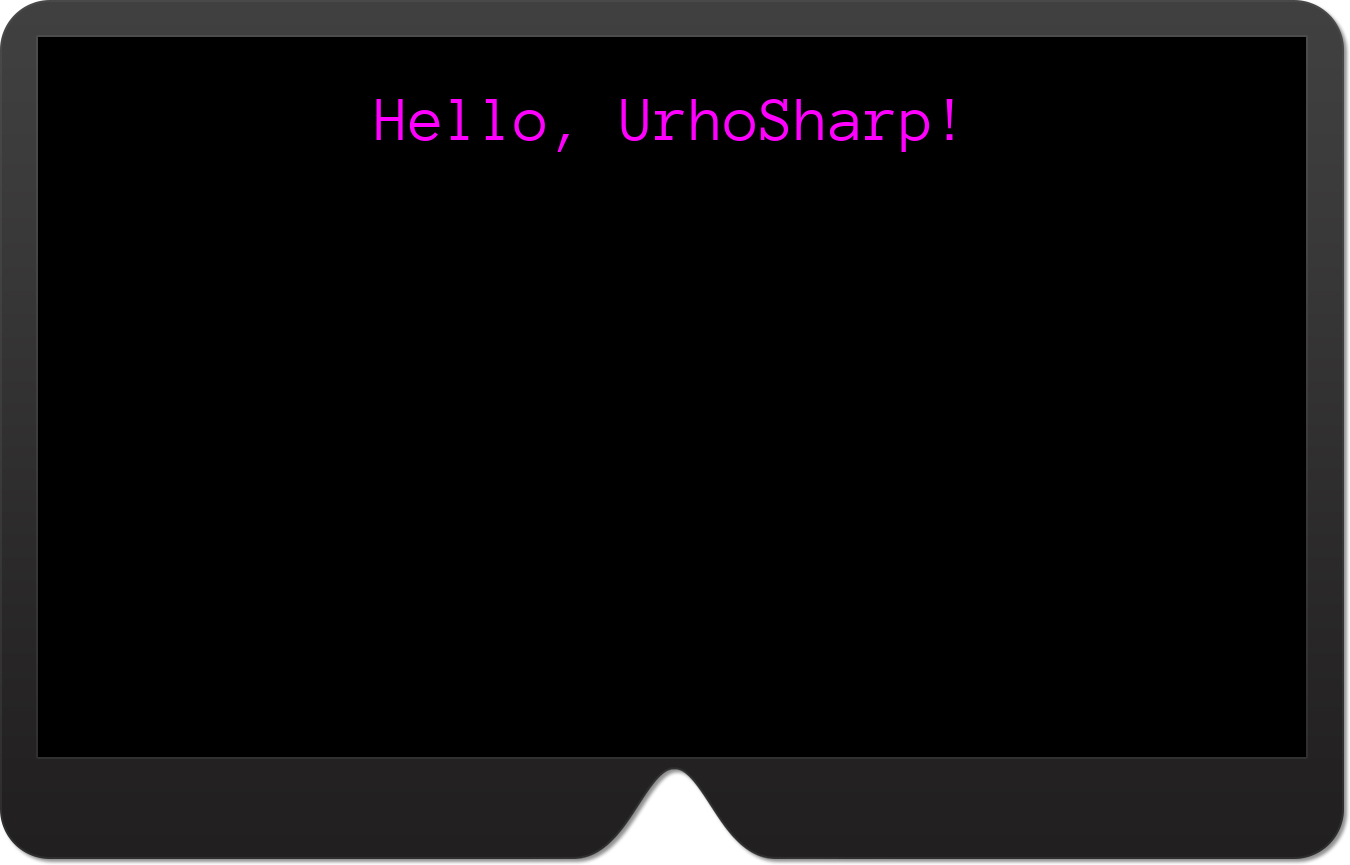
The code from Listing 15-2 implements the minimal entry point for the UrhoSharp app. The class presented there derives from StereoApplication and implements an empty constructor. The constructor is the only required element to be implemented manually. The app, however, does not do anything. To rectify that, let’s create the Text class in UrhoSharp to display static text that reads “Hello, UrhoSharp!” (See Figure 15-4.) To implement this functionality, add the field and method in Listing 15-3 to the MixedRealityApplication class.
LISTING 15-3 Creating static text
private Text text;
private void CreateText(string caption, Color color, float fontSize = 48.0f)
{
text = new Text()
{
Value = caption,
HorizontalAlignment = HorizontalAlignment.Center,
Position = new IntVector2(0, 50)
};
text.SetColor(color);
text.SetFont(CoreAssets.Fonts.AnonymousPro, fontSize);
UI.Root.AddChild(text);
}
The CreateText method from Listing 15-3 accepts two arguments:
- caption This argument specifies the text to be displayed.
- fontSize This argument specifies the font size. It is optional and has a default value of
48.
Given these arguments, CreateText proceeds as follows:
- It instantiates the
Urho.Gui.Textclass and stores the resulting object in the privatetextfield. - During initialization, the following public members of the
Textobject are configured:- Value This indicates the text to be displayed. Here, this value is set according to the
captionargument passed to theCreateTextmethod. - HorizontalAlignment This specifies the horizontal text alignment. Here, the text is centered.
- Position This allows you to indicate the absolute text position, represented as a two-dimensional vector of integers. These vectors are represented in UrhoSharp as instances of the
Urho.IntVector2struct. Here, this struct is used to add a vertical shift by 50 pixels with respect to the top edge of the view.
- Value This indicates the text to be displayed. Here, this value is set according to the
- The
SetColorinstance method is used to change the foreground color of the text. - The font and font size are set for rendering using the
SetFontmethod. This method has two versions. Both accept two arguments:- font or fontName This specifies the font to be used. In the first case, the argument is an instance of the
Urho.Gui.Fontclass, being an abstract representation of the font. In the second case, you need to provide the string representing the font. - fontSize This indicates the font size.
You can access all fonts available by default through the
Fontsproperty of theUrho.CoreAssetsstatic class. By default, there is only one font,AnonymousPro. This font is used in Listing 15-3.
- font or fontName This specifies the font to be used. In the first case, the argument is an instance of the
- The text is added to UI of the UrhoSharp application using the following statement:
UI.Root.AddChild(text);
Let’s use the CreateText method. To do so, you override the Start method, as shown in Listing 15-4. You can now run the app in the HoloLens emulator to see results from Figure 15-4.
LISTING 15-4 Creating the text object
protected override void Start()
{
base.Start();
CreateText("Hello, UrhoSharp!", Color.Magenta);
}
To wrap up this section, let’s discuss the Start method. This method is similar to the Unity script Start method. In UrhoSharp, the Start method is invoked to start the application. So, you typically use Start method to set up your scene. Hence, the CreateTest method is invoked there. As with Unity, the Start method is supplemented by the OnUpdate method, which is invoked whenever the application is updated during runtime, including scene rendering.
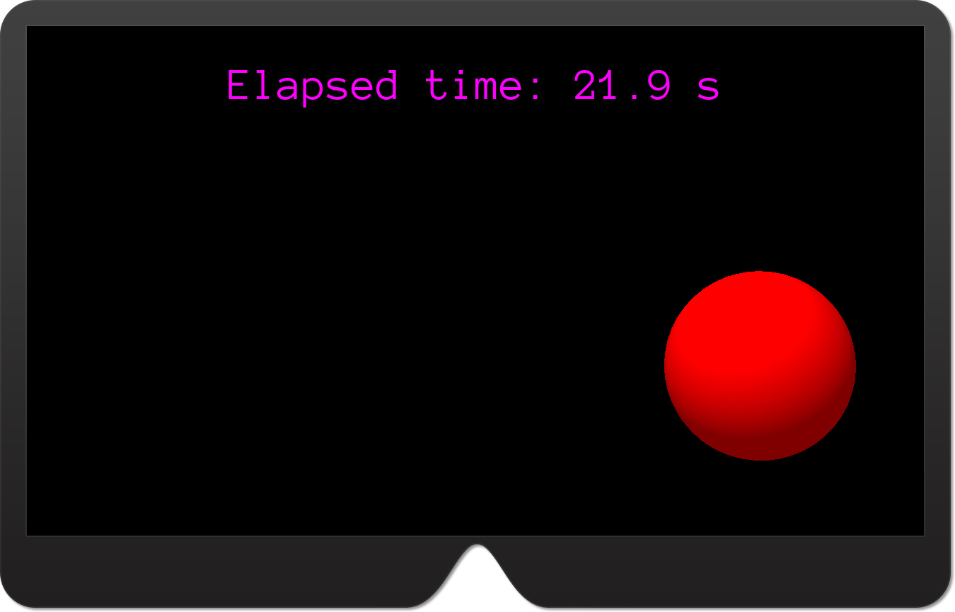
Let’s implement the OnUpdate method in the ExploringUrhoSharp app, as shown in Listing 15-5. The app will now display the time elapsed since it was started instead of a static string. (See Figure 15-5.)
LISTING 15-5 Updating text
protected override void OnUpdate(float timeStep)
{
base.OnUpdate(timeStep);
// Update text
text.Value = $"Elapsed time: {Time.ElapsedTime:F1} s";
}
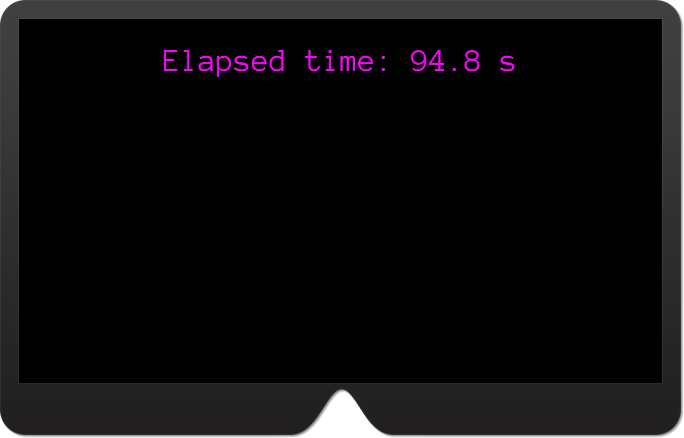
OnUpdate method.The OnUpdate method takes one argument, timeStep. This is a floating number that represents the time since the last application update. In principle, this argument can be used to manually calculate the time since the app was started. However, this time is already determined by UrhoSharp, and as Listing 15-6 shows, can be obtained by reading the ElapsedTime property of the Urho.Application class.
Adding Primitive Components and Materials
Like Unity, the Urho3D engine arranges all scene objects into a hierarchy of nodes, with the scene node on top. These nodes are represented as instances of the Urho.Node class. As with Unity, you can create new nodes as descendants of the scene node. These descendants can become ascendants for other nodes. Multiple descendants can have the same parent. So, objects in the scene can be easily grouped to manipulate them quickly.
Nodes are like Unity’s game objects. They have a specified scale, rotation, and position in the scene, but are not very useful until you supplement them with components. These components define a node’s appearance and behavior. To define a node’s appearance, you can use external models or start with primitive 3D components. In UrhoSharp, primitive 3D shapes are represented as classes, declared under the Urho.Shapes namespace:
BoxConeCylinderPlanePyramidSphereTorus
All these classes derive from a base Shape class. This class provides basic functionality used by the Urho engine to render the component. In particular, the Shape class has a Model property that returns the path used to render an object. The Shape class also has a Color property, which you can use to quickly change the shape material.
When the UrhoSharp app starts, the root node is created automatically. You can access this node by reading the Scene property of the StereoApplication class. Then, to create a new node, you can use either the constructor of the Node class or the Scene.CreateChild method. After the node is created, you add it to the scene using the Scene.AddChild method.
To see how this approach works in practice, implement the CreateNode method in the MixedRealityApplication class. (See Listing 15-6.) This method takes two arguments: position and scale. Then, the method creates a new instance of the Node class and sets the node position and scale according to input arguments. Finally, the node is added to the scene using the Scene.AddChild method.
LISTING 15-6 Creating the scene node
private Node CreateNode(Vector3 position, float scale)
{
var node = new Node()
{
Position = position,
Scale = scale * Vector3.One
};
Scene.AddChild(node);
return node;
}
Listing 15-6 uses the Node class constructor. An alternative approach would be to use the Scene.CreateChild method as shown in Listing 15-7. The difference is that with the Scene.CreateChild method, you need not invoke the Scene.AddChild method (because the node is automatically added as the scene’s descendant), but you cannot use the C# object initializer syntax to set the node’s property.
LISTING 15-7 Creating the child node
private Node CreateSceneChildNode(Vector3 position, float scale)
{
var node = Scene.CreateChild();
node.Position = position;
node.Scale = scale * Vector3.One;
return node;
}
You will now use the CreateNode method to add three primitive objects to the scene: a sphere, pyramid, and box. Each of these will be created using a dedicated helper method. Start by implementing the CreateSphere method from Listing 15-8.
LISTING 15-8 Creating the sphere node
private Node sphereNode;
private void CreateSphere(Color color)
{
sphereNode = CreateNode(new Vector3(0.15f, 0, 1f), 0.1f);
// Add sphere component
sphereNode.CreateComponent<Sphere>().Color = color;
}
Listing 15-8 shows how to add a sphere component to the node. To add a component, you use the Node.CreateComponent generic method, whose parameter defines the component type. This type must derive from the Urho.Component class that serves as the base for all components in UrhoSharp. The Component class is also used to define the Shape class through the following level of inheritance:
Shape -> StaticModel -> Drawable -> Component
Accordingly, you can use any of the previously listed classes representing a shape as a parameter of the Node.CreateComponent method. Listing 15-8 uses this functionality to add a sphere. Once this is done, the sphere color is adjusted according to the input argument of the CreateSphere method. (See the method declaration in Listing 15-8.)
After implementing the CreateSphere method, you place it in the Start method, as shown in Listing 15-9. You can then run the app in the HoloLens emulator to see the results depicted in Figure 15-6. Note that the sphere is located in the right part of the view. This is controlled by the node position (refer to Listing 15-7 and Listing 15-8). It is instructive to experiment with this position to see how it affects the appearance of the sphere in the scene.
LISTING 15-9 Displaying the sphere
protected override void Start()
{
base.Start();
CreateText("Hello, UrhoSharp!", Color.Magenta);
CreateSphere(Color.Red);
}
Let’s continue this example and implement another helper method: CreatePyramid. (See Listing 15-10.) CreatePyramid works a lot like CreateSphere. However, CreatePyramid uses a Material property to change the primitive’s color. To programmatically create the material, you use static methods of the Urho.Material class. For example, to make a uniform material of a specified color, you use the Material.FromColor method. (See Listing 15-10.) You can also create a material from an image using Material.FromImage. In this latter case you will need to specify the image path.
LISTING 15-10 Creating a pyramid
private Node pyramidNode;
private void CreatePyramid(Color color)
{
pyramidNode = CreateNode(new Vector3(-0.2f, 0, 1.25f), 0.1f);
// Add pyramid component
pyramidNode.CreateComponent<Pyramid>().Material = Material.FromColor(color);
}
Implement a third helper method, CreateBox. Listing 15-11 shows how to do so, and how to rotate the box component 30 degrees along the x-axis. The rotation occurs in the last statement in Listing 15-11, which uses the Rotate method of the Node class instance. This method accepts two arguments:
- delta This is an instance of the
Quaternionclass that represents the rotation. In Listing 15-11 an instance of theQuaternionclass is created with theFromAxisAnglestatic method. This method requires you to provide information about the axis along which the rotation will occur and an angle of rotation expressed in degrees. (The axis is represented as aVector3class instance because you can rotate an object along three axes at once.) - space This represents the space in which the rotation should be performed. It can be a local, parent, or world space. These spaces are represented by corresponding values from the
Urho.TransformSpaceenumeration.
LISTING 15-11 Creating a box
private Node boxNode;
private void CreateBox(Color color)
{
boxNode = CreateNode(new Vector3(0, -0.025f, 1f), 0.1f);
// Add box component
boxNode.CreateComponent<Box>().Color = color;
// Rotate the node
boxNode.Rotate(Quaternion.FromAxisAngle(Vector3.Right, 30));
}
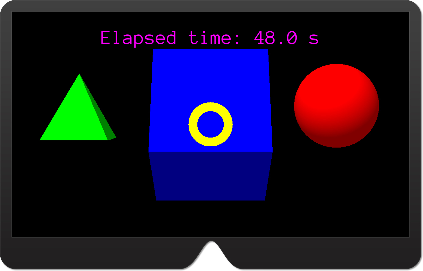
Finally, use the CreatePyramid and CreateBox methods to display the pyramid and the box within the scene. (See Listing 15-12.)
LISTING 15-12 A modified Start method of the MixedRealityApplication class
protected override void Start()
{
base.Start();
CreateText("Hello, UrhoSharp!", Color.Magenta);
CreateSphere(Color.Red);
CreatePyramid(Color.Green);
CreateBox(Color.Blue);
}
Run the modified app. You should get the result depicted in Figure 15-7.

Handling the Gaze
You will now extend the ExploringUrhoSharp app by another node, which will serve as the gaze indicator. The SharpReality extension to UrhoSharp provides a dedicated component for just this purpose: Urho.SharpReality.SpatialCursor. This component acts as a virtual pointer, showing which direction the user is looking. SpatialCursor also implements raycasting logic, which can be used to interact with holograms.
By default, SpatialCursor displays a cyan torus. (See Figure 15-8.) Whenever the user gazes at the hologram, SpatialCursor plays an animation that enlarges the cursor by a factor of six. (See Figure 15-9.) In this section, you will learn how to use this cursor in the ExploringUrhoSharp app to indicate gaze direction. Then you will alter the cursor color and use raycasting to store a reference to the node (representing a hologram) the user is gazing at. You will use this reference later in this chapter to manipulate the holograms with gestures.
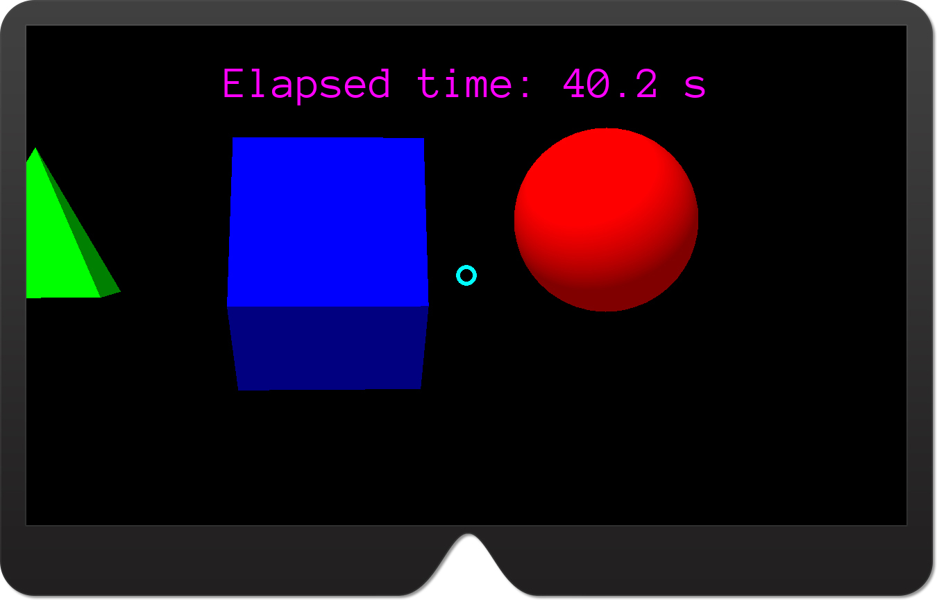
SpatialCursor component.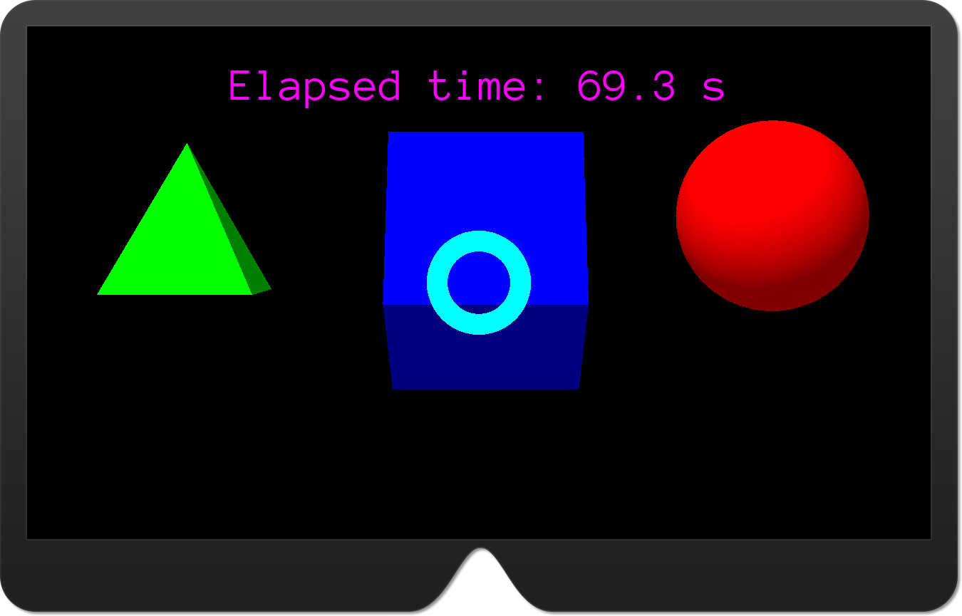
Indicating Gaze Direction
To indicate the gaze direction, extend the MixedRealityApplication class by adding the CreateSpatialCursor helper method from Listing 15-13. This method adds a new child node to the scene, and then supplements that node with the SpatialCursor component and the Node.CreateComponent generic method.
LISTING 15-13 Creating a spatial cursor
private Node spatialCursorNode;
private void CreateSpatialCursor()
{
// Create cursor node
spatialCursorNode = Scene.CreateChild();
// Add SpatialCursor component
var spatialCursorComponent = spatialCursorNode.CreateComponent<SpatialCursor>();
}
Next, invoke the CreateSpatialCursor in the Start method, as shown in Listing 15-14.
LISTING 15-14 Adding the gaze indicator to the scene when the app is started
protected override void Start()
{
base.Start();
// Text
CreateText("Hello, UrhoSharp!", Color.Magenta);
// 3D primitives
CreateSphere(Color.Red);
CreatePyramid(Color.Green);
CreateBox(Color.Blue);
// Spatial cursor (gaze indicator)
CreateSpatialCursor();
}
Run the app to see the results shown in Figures 15-8 and 15-9. While gazing around the scene, you will see that the cyan torus is not very visible on the green pyramid. To fix this, change the cursor color to yellow to increase the contrast between the cursor and all holograms in the scene. To do so, you must modify the cursor’s shader by setting the MatDiffColor parameter by extending the CreateSpatialCursor method as shown in Listing 15-15.
LISTING 15-15 Modifying the cursor color
private void CreateSpatialCursor()
{
// Create cursor node
spatialCursorNode = Scene.CreateChild();
// Add SpatialCursor component
var spatialCursorComponent = spatialCursorNode.CreateComponent<SpatialCursor>();
// Get the static model of the cursor
var staticModel = spatialCursorComponent.CursorModelNode.GetComponent<StaticModel>();
// ... and change its color from cyan to yellow
staticModel.Material.SetShaderParameter("MatDiffColor", Color.Yellow);
}
The CreateSpatialCursor method in Listing 15-15 obtains a reference to the StaticModel component associated with SpatialCursor. StaticModel represents the torus. After the reference to this model is obtained, you can use its Material property to set the shader parameter using the SetShaderParameter method. As shown in the last statement in Listing 15-15, SetShaderParameter accepts two arguments:
- name This is the name (represented as a string) of the shader parameter. You can obtain a list of available shader parameter names by reading static properties of the
CoreAssets.ShaderParametersclass. For instance, to obtainMatDiffColor(a parameter name used in Listing 15-14), you could useCoreAssets.ShaderParameters.MatDiffColor. - value This is the value for the parameter. This value can be one of 14 types, including simple types like
bool,int, andfloat, or complex types likeVector3, Color, orQuaternion.
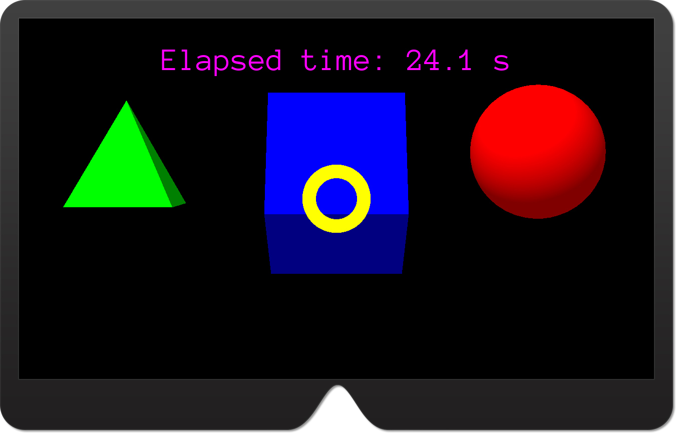
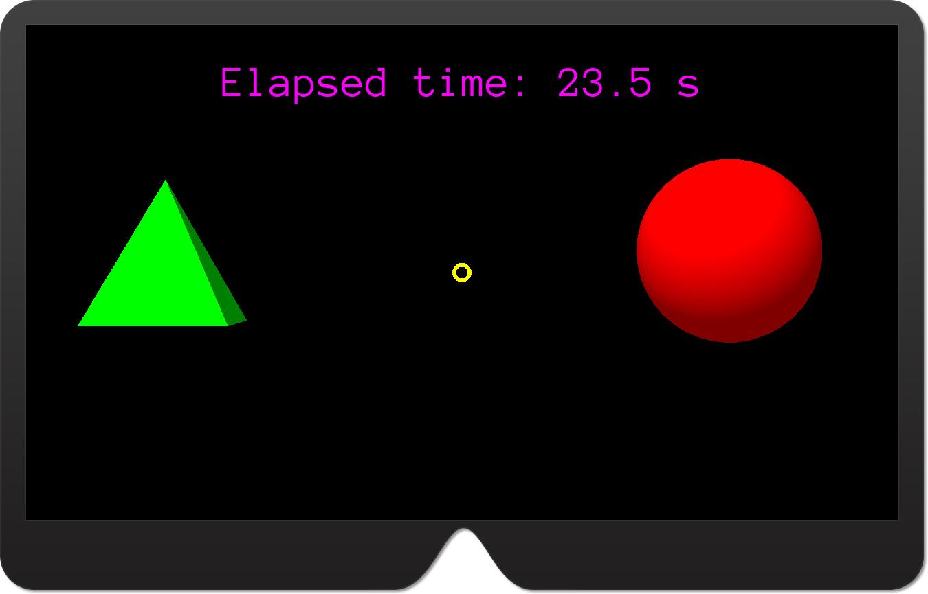
Run the app. You will see that the cursor color has changed from cyan to yellow. (See Figure 15-10.)
Raycasting
To detect whether the gaze indicator intersects a hologram, the SpatialCursor component uses raycasting. Raycasting in UrhoSharp works like it does in Unity. A 3D engine sends a ray toward the scene and checks whether it has intersected an object. To create a ray, you use the Urho.Ray structure with a default constructor that accepts two arguments: origin and direction. Alternatively, you can use one of the following from the Camera component:
- GetScreenRay This accepts two arguments,
xandy(representing normalized coordinates), to create an instance of theRaystruct that originates from the camera position and moves toward a given point. - GetScreenRayForMouse This works like
GetScreenRay, but the ray origin is set according to the pointer position within the scene view.
After the ray is created, you send it toward the scene using the Raycast or RaycastSingle method of the Octree class. Octree is the component that implements spatial partitioning. An instance of this component is automatically added to StereoApplication. Raycast and RaycastSingle return either a collection (Raycast) or a single instance (RaycastSingle) of the RayQueryResult struct. This struct contains information about the node hit by the ray (Node) and the point of the intersection (Position).
Listing 15-16 shows code that casts a ray toward the middle of the screen and then prints an identifier of the detected scene’s node in the debugger console. If the ray does not intersect any node, the code outputs a Nothing detected string instead. To create a ray, I used the GetScreenRay method of the LeftCamera property. This is the Camera component that corresponds to the left eye of the user and was automatically created by the StereoApplication class.
LISTING 15-16 A sample usage of raycasting
private void RaycastTest()
{
// Create ray
var ray = LeftCamera.GetScreenRay(0.5f, 0.5f);
// Send the ray toward the scene
var raycastResult = Octree.RaycastSingle(ray);
// Debug information about the detected nodes
var debugInfo = "Nothing detected";
if (raycastResult.HasValue)
{
debugInfo = $"ID from the RaycastTest: {raycastResult.Value.Node.ID}";
}
System.Diagnostics.Debug.WriteLine(debugInfo);
}
We will test this method in the next section, when learning about gestures. The reason I’m showing it here is that a similar approach is used internally by the SpatialCursor component. Moreover, SpatialCursor fires a Raycasted event whenever the ray is cast, which is provided with an instance of the RayQueryResult struct. So, you can use this event to quickly detect whether the user is gazing at the hologram without the need to write the raycasting logic yourself. You only need to analyze RayQueryResult.
Listing 15-17 shows how to use the Raycasted event to obtain a reference to the scene’s node, representing a hologram. First, you wire the method with a Raycasted event (see the last statement of the CreateSpatialCursor method in Listing 15-17). Then, you declare a private member, focusedNode, of type Node. Finally, you define the event handler (SpatialCursorComponent_Raycasted) that rewrites the reference of the intersecting node to focusedNode (when the hologram is detected) or sets it to null (when the user is not looking at the hologram). In this way you achieve a logic similar to that discussed in the “Configuring Gaze Input” section of Chapter 12. Note that here we implemented the gaze-related logic more easily than with Unity.
LISTING 15-17 Using the Raycasted event of the SpatialCursor component
private void CreateSpatialCursor()
{
// Create cursor node
spatialCursorNode = Scene.CreateChild();
// Add SpatialCursor component
var spatialCursorComponent = spatialCursorNode.CreateComponent<SpatialCursor>();
// Get the static model of the cursor
var staticModel = spatialCursorComponent.CursorModelNode.GetComponent<StaticModel>();
// ... and change its color from Cyan to Yellow
staticModel.Material.SetShaderParameter("MatDiffColor", Color.Yellow);
// Handle raycasted event
spatialCursorComponent.Raycasted += SpatialCursorComponent_Raycasted;
}
private Node focusedNode;
private void SpatialCursorComponent_Raycasted(RayQueryResult? obj)
{
if (obj.HasValue)
{
focusedNode = obj.Value.Node;
}
else
{
focusedNode = null;
}
}
Adding Gestures and Actions
In this section you will extend the ExploringUrhoSharp app by adding support for gestures. Specifically, you will implement methods to handle tap, double-tap, and manipulation gestures. The tap gesture will be used to verify the RaycastTest method from the previous section. The double-tap gesture will be used to animate focused holograms with actions. Finally, the manipulation gesture will be used to translate a hologram that was selected through the user’s gaze. You will also implement a hold gesture.
To detect gestures, the SharpReality extension of the UrhoSharp uses a SpatialGestureRecognizer class, which comes from the Windows 10 API, declared under the Windows.UI.Input.Spatial namespace. SharpReality implements a thin layer on top of the SpatialGestureRecognizer to further simplify the code that you need to handle gestures.
The general approach is to first enable the recognizer for the particular gesture. To enable or disable a gesture recognizer, you use the following properties of the object, deriving from StereoApplication:
- EnableGestureTapped Use this to enable or disable the tap and double-tap gesture recognizer. (These are detected through the same recognizer.)
- EnableGestureManipulation Use this to enable or disable the manipulation gesture.
- EnableGestureHold Use this to enable or disable the hold gesture. To perform the hold gesture you start with a tap and then keep your fingers together.
You enable gesture recognizers in the Start method. You then override the event handler that is fired whenever a particular gesture is detected. These events handlers must be overridden within the class that derives from StereoApplication. Here is the list of gestures along with their associated event handlers:
- Tap
OnGestureTapped - Double-tap
OnGestureDoubleTapped - Manipulation
OnGestureManipulationStarted,OnGestureManipulationUpdated,OnGestureManipulationCompleted, andOnGestureManipulationCanceled - Hold
OnGestureHoldStarted,OnGestureHoldCompleted, andOnGestureHoldCanceled
This is similar to what you can do with Unity, except that UrhoSharp.SharpReality does not provide a recognizer for the navigation gesture.
Let’s see how to use this approach in practice. Along the way, you will use actions to modify the hologram’s properties. Actions are reusable objects that let you smoothly modify scene node properties over a specified time frame. In this respect, actions are like animations, since both change object’s properties temporarily. There are numerous built-in actions. All of them are defined under the Urho.Actions namespace. Moreover, you can create your own actions by subclassing the Urho.Actions.BaseAction class. Later in this chapter you will learn how to use the ScaleTo and TintBy actions.
Tap
To implement the logic for the tap gesture, begin by adding two statements to the Start method of the MixedRealityApplication class as shown in Listing 15-18.
LISTING 15-18 Enabling recognizers for tap gestures
protected override void Start()
{
base.Start();
// Text
CreateText("Hello, UrhoSharp!", Color.Magenta);
// 3D primitives
CreateSphere(Color.Red);
CreatePyramid(Color.Green);
CreateBox(Color.Blue);
// Spatial cursor (gaze indicator)
CreateSpatialCursor();
// Gestures
EnableGestureTapped = true;
EnableGestureManipulation = true;
}
Then, you implement the event handler for the tap gesture as shown in Listing 15-19.
LISTING 15-19 Handling tap gesture
public override void OnGestureTapped()
{
base.OnGestureTapped();
RaycastTest();
}
To test this example, run the app in the emulator. Then gaze at the hologram and right-click the pointer. An identifier of the scene’s node associated with the hologram will be displayed in the debugger console, as shown in Figure 15-11.
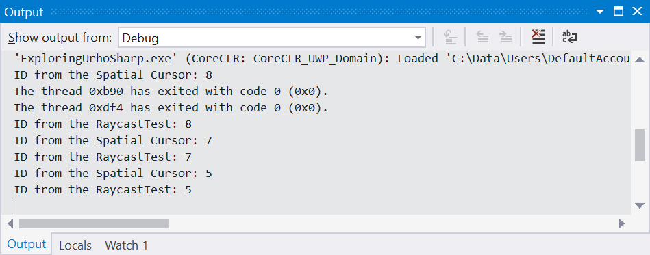
SpatialCursor component.You can confirm that this ID agrees with the raycasting used internally by the SpatialCursor component. To do so, modify the SpatialCursorComponent_Raycasted event handler (refer to Listing 15-17) as shown in Listing 15-20.
LISTING 15-20 Obtaining the ID of the hologram at which the user is gazing
private void SpatialCursorComponent_Raycasted(RayQueryResult? obj)
{
if (obj.HasValue)
{
if (focusedNode != obj.Value.Node)
{
System.Diagnostics.Debug.WriteLine(
$"ID from the Spatial Cursor: {obj.Value.Node.ID}");
}
focusedNode = obj.Value.Node;
}
else
{
focusedNode = null;
}
}
Double-tap
You will now write the logic for the double-tap gesture. To do so, you modify the OnGestureDoubleTapped event handler such that the focused hologram will be rescaled by 50% before reverting to the original value after a short while. To make this scaling smooth, you will use ScaleTo action. To proceed, add the following statement to the MixedRealityApplication.cs file:
using Urho.Actions
Then implement the OnGestureDoubleTapped event as shown in Listing 15-21.
LISTING 15-21 Rescaling the focused hologram with the double-tap gesture
public override void OnGestureDoubleTapped()
{
base.OnGestureDoubleTapped();
if (focusedNode != null)
{
var duration = 0.5f;
var originalScale = focusedNode.Scale.X;
var intermediateScale = originalScale * 1.5f;
focusedNode.RunActions(
new ScaleTo(duration, intermediateScale),
new ScaleTo(duration, originalScale));
}
}
The method from Listing 15-21 works as follows:
- It invokes the base
OnGestureDoubleTappedfunctionality. - It uses an
ifstatement to check whether the user is gazing at a hologram. Theifstatement ensures that a value stored in thefocusedNodeprivate member is notnull. - If the
focusedNodeprivate member is not null, three local variables are declared:- duration This variable specifies how long the rescaling action will apply. Here, this value will be half a second for each action. In this time, the hologram will change from the original scale (obtained by reading the
Scale.Xproperty of thefocusedNodefield; uniform scaling is assumed) to its intermediate scale and back to its original scale. - originalScale This stores the value for the original scale.
- intermediateScale This stores the value for the intermediate scale. In this example the
intermediateScalevalue is 1.5 times larger than theoriginalScalevalue.
- duration This variable specifies how long the rescaling action will apply. Here, this value will be half a second for each action. In this time, the hologram will change from the original scale (obtained by reading the
- The
duration,originalScale, andintermediateScalevariables are used to instantiate two instances of theScaleToclass. This class changes the scale of the selected node from the current value to the specified one. In the preceding code, the first instance of theScaleToclass rescales the hologram to the scale stored in theintermediateScalevariable, while the second instance changes the scale back to the scale stored in theoriginalScalevariable. As the last statement in Listing 15-21 shows, these actions are invoked by aRunActionsmethod of theNodeclass.RunActionsaccepts a list of actions to be invoked. You can add as many actions as you wish.
To test the preceding code, run the app in the HoloLens emulator, gaze at any hologram, and then right-click the pointer twice. The hologram will be rescaled. (See Figure 15-12.)
Manipulation
Typically, the manipulation gesture is used to manipulate the hologram to change its location or size. Here, you will implement logic that translates a scene’s node associated with the hologram that was previously selected by a user’s gaze.
Start by implementing the OnGestureManipulatonStarted event handler, as shown in Listing 15-22. This event, along with supporting private members, is used to configure logic to translate the hologram. The supporting private members are as follows:
- manipulatedHologram This is used to store the reference to the hologram at which the user is gazing when the manipulation gesture begins. (The reference is stored because
focusedNode, which is a reference to the gazed hologram, can change tonullwhen the hologram is translated out of theSpatialCursorcomponent.) - previousHandPosition This is used to implement the
OnGestureManipulationUpdatedevent handler. (See Listing 15-23.) Specifically,previousHandPositioncalculates the relative difference of user’s hand position when he or she performs the manipulation gesture. Hand positions are provided toOnGestureManipulationUpdatedas an instance of theVector3vector.
LISTING 15-22 Handling of the manipulation gesture
private Node manipulatedHologram;
private Vector3 previousHandPosition;
public override void OnGestureManipulationStarted()
{
base.OnGestureManipulationStarted();
manipulatedHologram = focusedNode;
previousHandPosition = Vector3.Zero;
}
LISTING 15-23 Updating a hologram position during a manipulation gesture
public override void OnGestureManipulationUpdated(Vector3 relativeHandPosition)
{
base.OnGestureManipulationUpdated(relativeHandPosition);
if (manipulatedHologram != null)
{
manipulatedHologram.Position += (relativeHandPosition - previousHandPosition);
previousHandPosition = relativeHandPosition;
}
}
As shown in Listing 15-23, OnGestureManipulationUpdated proceeds as follows:
- It invokes the functionality of the base class (
base.OnGestureManipulation). - It checks whether
manipulatedHologramis notnull. - If it is not
null, the object’sPositionproperty is changed according to the tracked user’s hand position. This difference is calculated by subtracting thepreviousHandPositionvalue from therelativeHandPositionvalue. (TherelativeHandPositionvalue is provided to theOnGestureManipulationUpdatedhandler by UrhoSharp.SharpReality.) - The value from
relativeHandPositionis rewritten to thepreviousHandPositionfield.
To complete the implementation, you need to add the OnGestureManipulationCompleted and OnGestureManipulationCanceled event handlers. As shown in Listing 15-24, you use these to reset the manipulatedHologram member to its default null value. This is used to prevent the manipulation of holograms not selected by the user when the manipulation gesture starts.
LISTING 15-24 Restoring the value of the manipulatedHologram field to its default value when the manipulation gesture ends or is canceled
public override void OnGestureManipulationCompleted(Vector3 relativeHandPosition)
{
base.OnGestureManipulationCompleted(relativeHandPosition);
manipulatedHologram = null;
}
public override void OnGestureManipulationCanceled()
{
base.OnGestureManipulationCanceled();
manipulatedHologram = null;
}
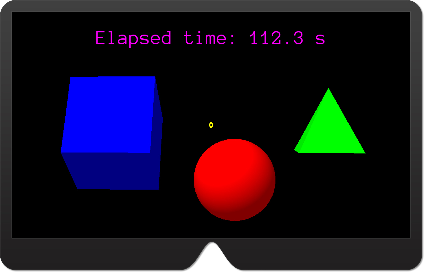
To test this code, run the app in the HoloLens emulator. Then, gaze at any hologram, press Alt on the keyboard, right-click the pointer, and start moving it to emulate a manipulation gesture. A focused object will be translated according to your input. (See Figure 15-13.)
Applying Physics
As discussed in previous chapters, one key element of many mixed reality apps is a physics simulation that makes holograms in the app behave like real objects. With UrhoSharp, you can quickly add components to nodes for these types of simulations. You control these simulations using the Urho.PhysicsWorld component, which interfaces with the Bullet library. An instance of the PhysicsWorld component is added to the root scene node. (This is performed automatically in StereoApplication, however.) You generally do not modify the default configuration of PhysicsWorld unless you need to optimize it. Instead, you add three other components to the child nodes associated with your holograms:
- RigidBody This represents a rigid body (similar to the
Rigidbodycomponent in Unity). - CollisionShape This defines the shape of an object that is used to detect collisions.
- Constraint This is used to define joints used to constrain two rigid bodies such that the movement of one body depends on the other one. (For instance, the distance between objects can be kept constant.) Joints can also define a constraint between a rigid body and an anchor point. Such a function is typically used to create a rope.
In this section, you will learn how to use RigidBody components so that holograms will be affected by gravity. When the user taps a focused hologram, it will fall down, as a real object would when released. Then, you will add a plane to the scene. After that, you will use CollisionShape to make this plane a virtual ground for holograms. Holograms will fall down on the plane. Next, you will use collision detection and actions to change the hologram’s color while it is bouncing off the plane. Finally, you will create a projectile that can be thrown toward other objects in the scene.
RigidBody
Start by adding the following statement to the MixedRealityApplication.cs file:
using Urho.Physics;
Then, extend the MixedRealityApplication class by adding the AddRigidBody helper method. (See Listing 15-25.)
LISTING 15-25 Adding a RigidBody component to the node
private RigidBody AddRigidBody(
Node node,
float mass = 1,
bool useGravity = true,
bool isKinematic = false,
float bounciness = 0.75f)
{
// Check whether RigidBody was already created
var rigidBody = node.GetComponent<RigidBody>();
if (rigidBody == null)
{
// If not, create the new one
rigidBody = node.CreateComponent<RigidBody>();
// Set the mass, gravity, and restitution (bounciness)
rigidBody.Mass = mass;
rigidBody.UseGravity = useGravity;
rigidBody.Kinematic = isKinematic;
rigidBody.Restitution = bounciness;
}
return rigidBody;
}
The method from Listing 15-25 accepts five arguments:
- node This is an instance of the
Nodeclass, representing the hologram to which theRigidBodycomponent should be added. - mass This is a mass of the rigid body. (The default value is 1.)
- useGravity This is a Boolean value indicating whether the rigid body should be affected by gravity. (The default value is
true.) - isKinematic This a Boolean value indicating whether the rigid body is kinematic. Kinematic rigid bodies do not change their position during physics simulations. This is useful for creating walls or blocking planes (as in this section).
- bounciness This value indicates how much the rigid body will bounce off the colliders. The higher the value, the lower the energy loss on collision. A value of
0indicates total loss, while a value of1indicates no loss. The default value is0.75.
These arguments (except node) are used to add a RigidBody component to the given node and configure it. In principle, the node can have the RigidBody component already attached. Hence, the method from Listing 15-24 uses a generic GetComponent method to check whether the node has this component. If the RigidBody component is not available, the AddRigidBody method will create a new instance of the component. Then, AddRigidBody sets the four properties of the RigidBody: Mass, UseGravity, Kinematic, and Restitution. The last of these defines the bounciness of the body as described. (I use the term bounciness to conform to the discussion in Chapter 10.)
You can now extend the OnGestureTapped event handler such that the focused hologram will be supplemented by the RigidBody component. (See Listing 15-26.)
LISTING 15-26 A modified version of the OnGestureTapped method
public override void OnGestureTapped()
{
base.OnGestureTapped();
RaycastTest();
if (focusedNode != null)
{
AddRigidBody(focusedNode);
}
}
To ensure everything is working as expected, run the app in the HoloLens emulator. Then, gaze at any hologram and right-click the pointer. The hologram should fall down. (See Figure 15-14.) Currently, it falls continuously, because there is nothing to stop it. In the next section, you will create the plane and use CollisionShape components so the hologram will fall on the plane.
CollisionShape
To configure the app so the scene nodes can collide with each other, you add a CollisionShape component. Afterward, you need to define the collider shape. This shape is used by the physics engine to calculate collisions between nodes. In general, the displayed shape can differ from the collider shape. This happens for complex objects that would require a lot of calculations to satisfy physical bounds. To optimize performance, it is reasonable to use an approximate geometry for collision detection.
To add colliders to the ExploringUrhoSharp app, start by adding a plane to the scene. This plane will be positioned below other 3D primitives to stop the primitives when they are falling down. To start, implement the CreatePlane method from Listing 15-27.
LISTING 15-27 Creating a plane
private Node planeNode;
private void CreatePlane(Color color)
{
planeNode = CreateNode(new Vector3(0, -0.25f, 1f), 0.75f);
planeNode.CreateComponent<Urho.Shapes.Plane>().Color = color;
AddRigidBody(planeNode, 10, false, true, 1);
AddCollisionShape(planeNode);
}
The method from Listing 15-27 proceeds similarly to the methods used to create a sphere (refer to Listing 15-8), pyramid (refer to Listing 15-10), and box (refer to Listing 15-11). First, it creates the new node (stored in the planeNode member), creates a Plane component, and sets its color. (Note that in this case, the fully qualified type name is used as a parameter of the CreateComponent method to avoid name conflicts.) After the Plane component is added to the node, the CreatePlane method invokes the AddRigidBody method to add the RigidBody component to planeNode. In this case, the mass of the planeNode’s rigid body is set to 10 (in the second argument of the AddRigidBody method), meaning the plane will be 10 times heavier than the other 3D primitives (the pyramid, box, and sphere). This mass difference will ensure that the plane will stop the primitives. Moreover, the plane will not use gravity (see the third argument of AddRigidBody), will be kinematic (see the fourth argument), and will have maximum bounciness (see the last argument). Finally, the CreatePlane method invokes the method to create and configure the collider for a plane. (See Listing 15-28.)
LISTING 15-28 Adding the collision shape
private CollisionShape AddCollisionShape(Node node)
{
var shape = node.GetComponent<Shape>();
if (shape == null)
{
return null;
}
else
{
return SetCollisionShape(node, shape);
}
}
The method from Listing 15-29 accepts one argument of type Node. This is an instance of the scene’s node, which should be supplemented by the CollisionShape component. Then, the method checks whether the provided node has an assigned Shape component. If not, the method returns null. Otherwise, the helper SetCollisionShape method is invoked. (See Listing 15-29.)
LISTING 15-29 Setting a shape for the collider
private CollisionShape SetCollisionShape(Node node, Shape shape)
{
var collisionShape = node.CreateComponent<CollisionShape>();
var one = Vector3.One;
var position = Vector3.Zero;
var rotation = Quaternion.Identity;
if (shape.GetType() == typeof(Sphere))
{
collisionShape.SetSphere(1, position, rotation);
}
else if (shape.GetType() == typeof(Box))
{
collisionShape.SetBox(one, position, rotation);
}
else if (shape.GetType() == typeof(Urho.Shapes.Plane))
{
var size = new Vector3(planeNode.Scale.X,
0.01f, planeNode.Scale.Z);
collisionShape.SetBox(size, position, rotation);
}
else if (shape.GetType() == typeof(Pyramid))
{
collisionShape.SetConvexHull(CoreAssets.Models.Cone,
0, one, position, rotation);
}
return collisionShape;
}
The SetCollisionShape method creates and adds the CollisionShape component to the given node. Then it declares three local variables: one, position, and rotation. These are reusable components used to configure the CollisionShape component. To that end, you use one of the methods that set the actual collider shape (or form). In Listing 15-29, the form of the collider is set depending on the Shape component previously associated with the node. Note that the Shape component defines what the node will look like, while CollisionShape determines how the node will act under collisions with other nodes.
To set the actual form of the collider, the SetCollisionShape uses four if statements. Each of these compares the node’s shape (obtained through the GetType method of the shape argument) to one of four types: Sphere, Box, Plane, and Pyramid. Then, the SetCollisionShape method invokes the corresponding method of the CollisionShape class instance:
- SetSphere This sets the form of the collider to a sphere. This method accepts three arguments, which define the collider diameter, position, and rotation,
- SetBox This sets the form of the collider to a box. Again, this method accepts three arguments, which define the collider size, position, and rotation. This method is used for the box and for the plane. In the second case, the size of the collider along the y-axis is set to
0.01. - SetConvexHull This sets the form of the collider to a convex hull depending on the model. In the preceding example, the
Conemodel is used to approximate the pyramid shape. (See the first argument of theSetConvexHullmethod.) The model is obtained from theConeproperty of theCoreAssets.Modelobject. The second argument of theSetConvexHullmethod lets you specify the level of detail, and the next three arguments define the scale, position, and rotation, respectively.
You use the CreatePlane and AddCollisionShape methods in the Start method of the MixedRealityApplication class as shown in Listing 15-30.
LISTING 15-30 A modified Start method of the MixedRealityApplication class
protected override void Start()
{
base.Start();
// Text
CreateText("Hello, UrhoSharp!", Color.Magenta);
// 3D primitives
CreateSphere(Color.Red);
CreatePyramid(Color.Green);
CreateBox(Color.Blue);
// Spatial cursor (gaze indicator)
CreateSpatialCursor();
// Gestures
EnableGestureTapped = true;
EnableGestureManipulation = true;
// Physics
CreatePlane(Color.Gray);
AddCollisionShape(sphereNode);
AddCollisionShape(pyramidNode);
AddCollisionShape(boxNode);
}
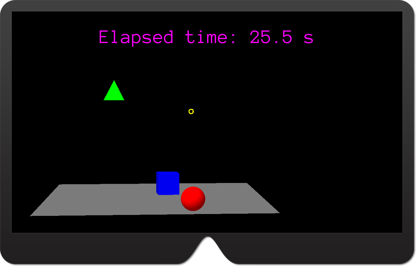
Test the solution by deploying the app to the HoloLens emulator. Then, press and hold the S key on the keyboard to virtually move backward within the scene. Keep the key pressed until you see the plane. Next, tap either the pyramid, box, or sphere. It will fall down and bounce off the plane. (See Figure 15-15.)
Detecting and Handling Collisions
The physics engine uses the following three events of the Node class to notify you when a collision happens and what the collision’s status is:
- NodeCollisionStart This event is fired when the collision starts.
- NodeCollision This event is raised when two colliders come in contact.
- NodeCollisionEnd This event is fired when the collision ends.
These events are accompanied by corresponding structs that describes them: NodeCollisionStartEventArgs, NodeCollisionEventArgs, and NodeCollisionEndEventArgs. Each of these structs has an OtherNode property, which identifies the node with which your node collided.
Listing 15-31 shows how to use the NodeCollision event of planeNode to change the tint of the node that hits the plane. First, you subscribe to the NodeCollision event. (See the first bolded statement in Listing 15-31.) Then, in the event handler (PlaneNode_NodeCollision), you obtain a reference to the node that collided with the plane (OtherNode). Finally, you run the TintBy action against OtherNode.
LISTING 15-31 Handling the plane’s NodeCollision event
private void CreatePlane(Color color)
{
planeNode = CreateNode(new Vector3(0, -0.5f, 1f), 1f);
planeNode.CreateComponent<Urho.Shapes.Plane>().Color = color;
AddRigidBody(planeNode, 10, false, true, 1);
AddCollisionShape(planeNode);
planeNode.NodeCollision += PlaneNode_NodeCollision;
}
private void PlaneNode_NodeCollision(NodeCollisionEventArgs obj)
{
var otherNode = obj.OtherNode;
otherNode.RunActions(new TintBy(0.5f, Color.White));
}
Run the app in the HoloLens emulator and move backward to see the whole scene. Then, tap the pyramid, box, or sphere. As it falls down and collides with the plane, the color gradually changes to white. (See Figure 15-16.)

Projectiles
In this section you will create a projectile similar to the yellow ball you created in Chapter 10. This ball will be thrown toward the scene on the double-tap gesture.
To begin, add a ThrowTheBall method to the MixedRealityApplication class. (See Listing 15-32.) Then, invoke it in OnGestureDoubleTapped, as shown in Listing 15-33.
LISTING 15-32 Creating and firing a projectile
private void ThrowTheBall(float speed)
{
// Create the new node
var ballNode = CreateNode(HeadPosition, 0.1f);
// Create the sphere component
ballNode.CreateComponent<Sphere>().Color = Color.Yellow;
// Configure physics
var ballRigidBody = AddRigidBody(ballNode, 0.5f);
AddCollisionShape(ballNode);
// Throw the ball toward the gaze direction
var ray = LeftCamera.GetScreenRay(0.5f, 0.5f);
ballRigidBody.SetLinearVelocity(ray.Direction * speed);
}
LISTING 15-33 Throwing the ball
public override void OnGestureDoubleTapped()
{
base.OnGestureDoubleTapped();
if (focusedNode != null)
{
var duration = 0.5f;
var originalScale = focusedNode.Scale.X;
var intermediateScale = originalScale * 1.5f;
focusedNode.RunActions(
new ScaleTo(duration, intermediateScale),
new ScaleTo(duration, originalScale));
}
ThrowTheBall(10);
}
The ThrowTheBall method (refer to Listing 15-32) creates a new node that will host the ball. The initial position of this node is the same as the user’s head position, which you obtain by reading the HeadPosition property of the StereoApplication class. The scale of the ball node is set to 0.1f. (See the second argument of the CreateNode method in Listing 15-32.) After the node is created, the ThrowTheBall method adds a Sphere component to the node whose color is Color.Yellow. Then, the ThrowTheBall method adds RigidBody and CollisionShape components to the sphere. The mass of the sphere is half the unit. This is controlled through the second argument of the AddRigidBody method. All other arguments of that method are left at their default values. So, RigidBody will use gravity, will not be kinematic, and will have a bounciness of 0.75. Afterward, ThrowTheBall defines the ball’s velocity vector using SetLinearVelocity of the RigidBody class instance. The velocity vector defines where and how fast the ball will go. Here, the ball will move toward the gaze direction. To determine this direction, ThrowTheBall creates a ray originating from the screen toward the middle of the view. Lastly, the velocity vector is multiplied by a speed scaling factor (obtained as a method argument). The larger the value, the faster the ball will move.
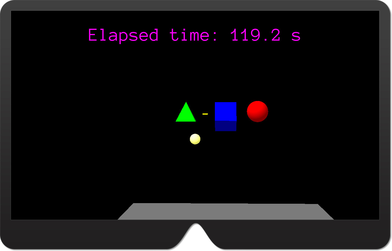
Run the app and perform a double-tap gesture. The yellow ball will be thrown toward the scene. The yellow ball will also change color after colliding with the plane due to the collision handler from Listing 15-31. (See Figure 15-17.)
Spatial Mapping
In this section you will learn how to use the spatial mapping by extending ExploringUrhoSharp to display surfaces detected by the HoloLens spatial-perception system. UrhoSharp.SharpReality provides a straightforward API to obtain spatial information. To begin, use the StartSpatialMapping method to start the observer. This method accepts an instance of the Vector3 class that defines the bounding box, which tells the spatial perception system which area should be observed to generate spatial mesh info. You can stop spatial perception by invoking the StopSpatialMapping method. When spatial perception is running, any updates to the recognized spatial mesh will be reported using the OnSurfaceAddedOrUpdated method. This method has two arguments:
- surface This an instance of the
SpatialMeshInfostruct, which contains details about the detected spatial mesh. This includes the unique identifier (SurfaceId), the timestamp (Date), a collection of spatial vertices that define the surface (VertexData), a collection of indices (IndexData), the location of the surface (BoundsCenter), its rotation (Rotation), and its size (Extents). - generatedModel This an instance of the
Modelclass that represents the shape of the surface.
In the following example, I will show you how to use the spatial mapping API from UrhoSharp.SharpReality to draw detected surfaces and then configure them as colliders. As a result, the yellow ball will bounce off the spatial meshes (similar to Chapter 12). Follow these steps:
- To declare the Spatial Perception capability, double-click the Package.appxmanifest file in the Solution Explorer.
- In the window that opens, click the Capabilities tab, and select the Spatial Perception checkbox. (See Figure 15-18.)

FIGURE 15-18 Declaring the Spatial Perception capability. - To enable spatial perception, modify the
Startmethod ofMixedRealityApplicationas shown in Listing 15-34. In this listing, the spatial observer is configured to monitor the spatial area within the volume of dimensions 5x5x5 m3. Note
NoteStartSpatialMappingis an asynchronous method. Hence, you need to add anasynckeyword to theStartmethod declaration.LISTING 15-34 Starting the spatial mapping
protected override async void Start()
{
base.Start();
// Text
CreateText("Hello, UrhoSharp!", Color.Magenta);
// 3D primitives
CreateSphere(Color.Red);
CreatePyramid(Color.Green);
CreateBox(Color.Blue);
// Spatial cursor (gaze indicator)
CreateSpatialCursor();
// Gestures
EnableGestureTapped = true;
EnableGestureManipulation = true;
// Physics
CreatePlane(Color.Gray);
AddCollisionShape(sphereNode);
AddCollisionShape(pyramidNode);
AddCollisionShape(boxNode);
// Spatial mapping
await StartSpatialMapping(new Vector3(5, 5, 5));
} - Implement
OnSurfaceAddedOrUpdatedas shown in Listing 15-35. This method is invoked whenever the spatial info changes. To ensure this, you change the room definition as in Chapter 12. You will see that the spatial meshes are redrawn.LISTING 15-35 Displaying the spatial mesh that will act as colliders
public override void OnSurfaceAddedOrUpdated(
SpatialMeshInfo surface, Model generatedModel)
{
base.OnSurfaceAddedOrUpdated(surface, generatedModel);
// Create the node for the spatial surface
var surfaceNode = CreateNode(surface.BoundsCenter, 1.0f);
surfaceNode.Rotation = surface.BoundsRotation;
// Create and configure the static model component
var staticModelComponent = surfaceNode.CreateComponent<StaticModel>();
staticModelComponent.Model = generatedModel;
staticModelComponent.ViewMask = 0x80000000;
// Set the wireframe material for the model
var material = Material.FromColor(Color.Gray);
material.FillMode = FillMode.Wireframe;
staticModelComponent.SetMaterial(material);
// Add the rigid body
AddRigidBody(surfaceNode, 10, false, true, 1);
// Create and configure the collider
var collisionShape = surfaceNode.CreateComponent<CollisionShape>();
collisionShape.SetTriangleMesh(generatedModel, 0, Vector3.One,
Vector3.Zero, Quaternion.Identity);
}
To display spatial meshes and configure them as colliders, the method from Listing 15-35 proceeds as follows:
- After invoking the base functionality (
base.OnSurfaceAddedOrUpdated), the method creates a new node for the spatial surface, stored in thesurfaceNodelocal variable. - The position and rotation of the node are set according to the
BoundsCenterandRotationproperties obtained from the instance of theSpatialMeshInfostruct. - You create the
StaticModelcomponent, which defines the visual appearance of the node. - The rendering model shape is set to an instance of the
Modelclass obtained from the second argument of theOnSurfaceAddedOrUdpatedmethod. This ensures that the surface will resemble the shape of the recognized real object. - The
ViewMaskproperty ofStaticModelis configured to prevent raycasting of spatial meshes. As a consequence,SpatialCursorwill not be upscaled when the user gazes at the spatial mesh. - The default material of the
StaticModelis changed to the gray wireframe. To set the wireframe rendering, you use theFillModeproperty of theMaterialclass instance. RigidBodyis added tosurfaceNode.CollisionShapeis created and configured. In this example, the collider shape is configured using theSetTriangleMeshof theCollisionShapeclass. This lets you precisely match the collider to the model.
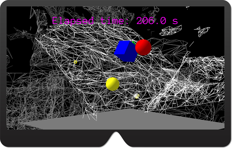
Deploy the app in the HoloLens emulator. You will see various lines representing the detected spatial meshes. To see that they indeed act as colliders, throw the ball toward them. The ball will bounce off them and can eventually stay put on flat surfaces. (See Figure 15-19.)
Summary
This chapter explored the most important features of UrhoSharp in terms of HoloLens development. You learned how to set up a project, implement the entry point, and create holograms with primitive components and materials. Then, you used SpatialCursor to indicate the gaze direction and employed raycasting to interact with holograms. After that you learned how to handle spatial gestures and use actions to quickly manipulate objects in the scene. In the last two sections you learned about components used for physics simulations and used spatial mapping to render spatial meshes.
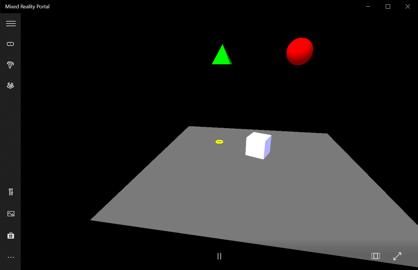
Although all examples were shown in the HoloLens emulator, you can also execute ExploringUrho
Sharp in the immersive headset without making any code changes. Just change the debug target from HoloLens emulator (see the top-right corner of Figure 15-3) to Local Machine. The app will be executed in the Mixed Reality Portal as shown in Figure 15-20. You can then test all the features except spatial mapping, which is unavailable with immersive headsets. Note that everything works the same as in HoloLens. The only difference is the larger field-of-view.