
Chapter 9
Unity Basics
This is the chapter where you start developing 3D apps for Windows Mixed Reality. To that end you will first explore the Unity Editor. After reviewing the main elements of this editor, you will learn how to create scenes with primitive and advanced 3D objects. Specifically, you will create simple objects such as planes, spheres, cubes, and cylinders, and more advanced elements like trees and characters.
To create an animated character, you will use the Unity Editor Ragdoll Creator. You will also explore using the Ragdoll Creator to control that character in a realistic way. Namely, this chapter will show you how to make your ragdoll fall down onto other objects in the scene. You will see that Unity provides mechanisms to make this vertical drop truthful. You will also learn how to use materials and prefabs to adjust the visual appearance of objects in the scene.
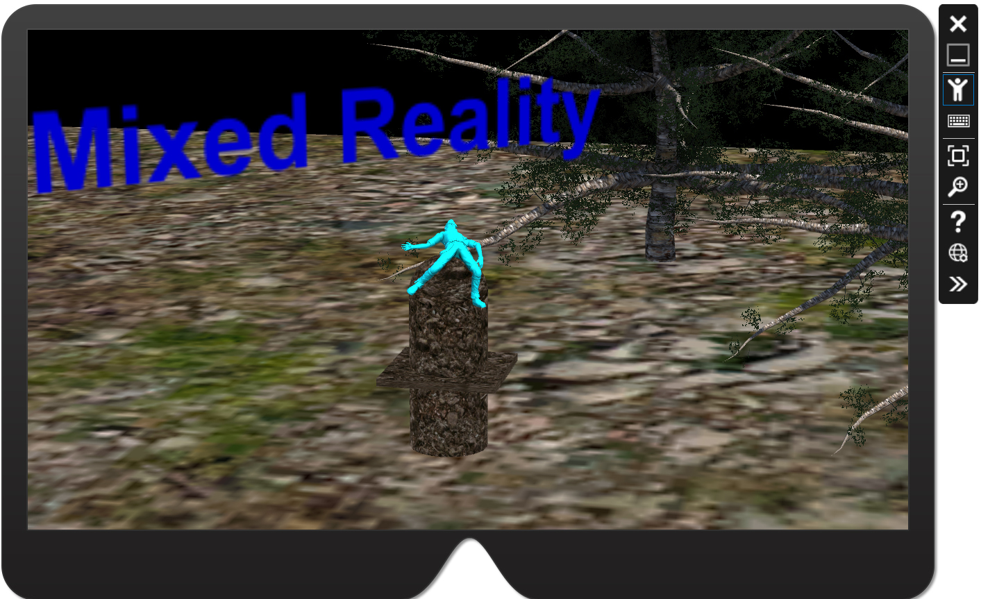
Finally, you will investigate how to build and deploy the app to achieve the result shown in Figure 9-1. This app comprises several objects. These include a plane, which represents the ground; 3D text; and a character (cyan humanoid model) that falls down and lands on a custom 3D object made from a cylinder, a cube, and a sphere. There are also trees, which sway like real trees in the wind.
The Unity Editor
This chapter starts by covering some important Unity concepts. After you grasp these, you will learn how to set up and use the Unity Editor to create your first scene.
Understanding Game Objects and Components
In Unity, every element in a scene, including lighting, terrain, and characters, is defined as a game object. A game object does not have any particular properties or perform any specific function until you supplement it with a component. Components define visual and functional properties for game objects. Every game object has a default transform component, which determines the position and dimensions of the game object in the scene.
![]() Note
Note
Because you will use Unity to create apps for Windows Mixed Reality, the objects you use will not be limited to typical game objects. Therefore, this chapter uses the terms scene object (or simply object) and game object interchangeably.
Configuring Your Unity ID and Signing In
When you run the Unity Editor, the Sign Into Your Unity ID dialog box opens. (See Figure 9-2.) Before you can use the Unity Editor, you must create a Unity ID. To do so, click the Create One link at the top of the Sign Into Your Unity ID dialog box. (Alternatively, use this link: http://bit.ly/unity_id.) Then, in the dialog box that appears, provide the information requested to create a Unity ID. This includes your name, a valid email address, and the user name and password you want to use. You must also agree to the terms of use. (For step-by-step instructions, including screenshots, see http://bit.ly/unity_activation.)

After you create your Unity ID, you choose a license. Unity offers three license tiers:
- Personal Unity offers this license free of charge, provided “your company currently does not make more than $100k in annual gross revenues or has not raised funds in excess of $100k.” This version contains all core modules. However, you cannot modify the splash screen the user sees when your app launches. (This license was used in the writing of this book.)
- Plus This license costs $35 per month. You can use this license if your company earns “up to $200k in annual gross revenues.” In addition to giving you access to all the core modules, this version also provides several packs, which enhance core Unity functionality, and lets you modify the splash screen.
- Pro This license costs $120 per month but allows for an “unlimited revenue or fundraising capacity.” This version extends the capabilities of the Plus version by including additional services, such as analytics and visualizations, and premium support.
After you create your Unity ID and choose a license, you use your Unity ID to sign into Unity. You’ll see a welcome screen like the one in Figure 9-3. This screen has two tabs:
- Projects Click this tab to create a new project (by clicking the New link in the upper-right corner of the screen) or to open an existing one (by clicking the Open link next to the New link and selecting the project you want to open).
- Learn Click this tab to access links to tutorials, tutorial projects, and resources that can help you jump-start developing apps with Unity.
Creating a New Project
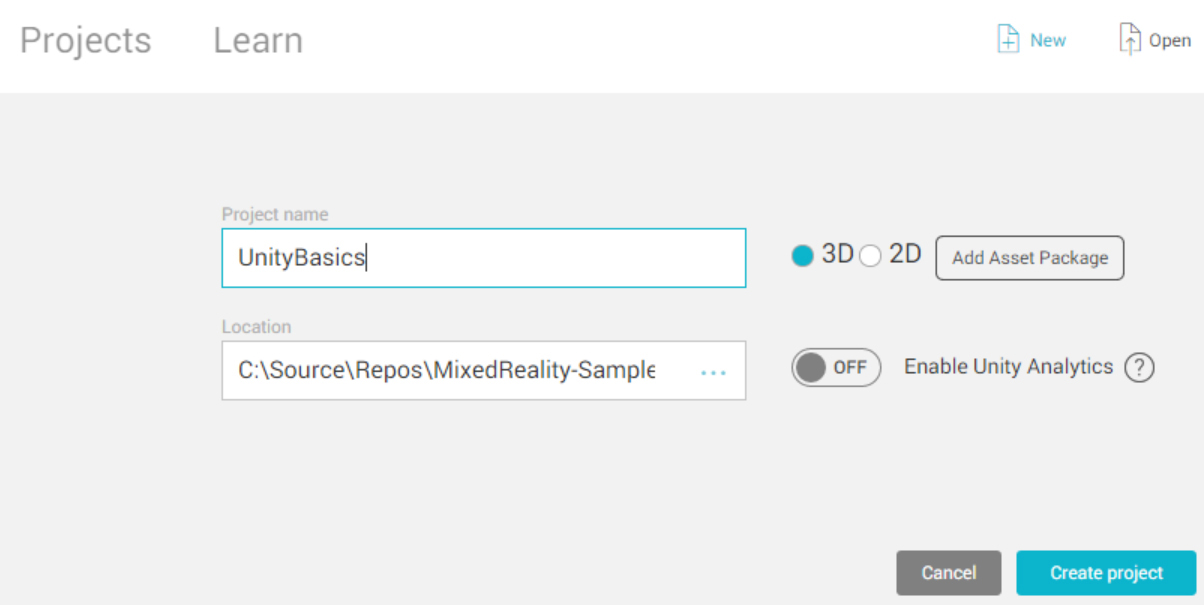
To create a new project, follow these steps:
- Click the New link in the Projects tab.
- Type a name for the project in the Project Name box. In this case, type UnityBasics.
- Select the 3D option button.
- Enter a location for the project’s source code in the Location box.
- Click the Create Project button.
After a moment, the Unity Editor will be open. (See Figure 9-4.) The main components of the Unity Editor are as follows:
- Toolbar
- Hierarchy window
- Scene view
- Inspector window
- Project window
The following sections cover each of these components.
![]() Note
Note
The window also features a menu bar, located above the toolbar. This component is self-explanatory and is not covered in more detail in the sections that follow.

![]() Note
Note
You can change the layout of the Unity Editor screen to suit your needs by dragging the Hierarchy, Inspector, and Project windows. This chapter assumes these windows are arranged in the default layout.
The Toolbar
The toolbar contains buttons that give you quick access to the Unity Editor’s most important features. Let’s briefly review them, starting with the controls located on the left:
- Drag, Move, Rotate, Scale, and RectTransform You use these buttons to position objects in the scene. (For more information, see http://bit.ly/positioning_objects.)
- Gizmo toggles These buttons, labeled Center and Local in Figure 9-4, enable you to toggle the gizmo handle position. You use these to define the center of a transform. (See http://bit.ly/positioning_objects for more information.)
- Play, Pause, and Step You use these buttons to control the execution of your app in the editor’s play mode. You use this mode to preview your app in Unity editor.
- Collab When you click this button, a pop-up window opens, which you use to manage Unity Collaboration. Unity Collaboration is a cloud-based service that enables you to store your project in the cloud so other members of your team can quickly see your changes and synchronize their work with yours.
- Cloud When you click this button, a pop-up window opens, where you can configure Unity services like Unity Ads, Unity Analytics, Unity Cloud Build, and others. (See http://bit.ly/unity_services for more details.)
- Account Clicking this button opens a menu that gives you access to tools to manage your account and license.
- Layers Clicking this button opens a menu containing layers to be displayed in the Scene view
- Layout Clicking this button—labeled Default in Figure 9-4—opens a menu with predefined layout options. Use this list to quickly rearrange windows of the Unity Editor. To restore the default arrangement, select the Default option.
The Hierarchy Window
The Hierarchy window (sometimes simply called the Hierarchy) presents a list of all objects in the current project. The Hierarchy is like Solution Explorer in Visual Studio but shows a list of objects composing the scenes instead of source code files composing projects. So, you use the Hierarchy window in much the same way you use the Solution Explorer.
By default, the Hierarchy window contains only two objects: a main camera object and a directional light object. To add new objects, you use the Hierarchy window’s context menu. As shown in Figure 9-5, this menu contains a list of built-in objects, which you can use to extend the default scene. You will learn about these objects later in this chapter.

Scene View
The Scene view is an interactive component in which you place and position all objects to compose your app. Typically you proceed as follows:
- You add objects using the Hierarchy window.
- You select the object using the Hierarchy window or through the Scene view.
- You position and transform the object using toolbar buttons or with the Inspector window. (See the next section.)
If you compare the Unity Editor workflow with the Visual Studio workflow, Scene view is like a Visual Designer that enables you to use a drag-and-drop approach to define the visual layer of your app.
By default, the Scene view contains three tabs. (Actually, they are separate windows, which you can move freely, but I will refer to them as tabs here.)
- Scene This tab displays the scene preview mode, which contains a Scene gizmo (in the top-right corner) and a control bar (along the top) to help you preview the scene. You’ll learn more about each of these tools in the following sections.
- Game View You use this tab to preview and test your final app—for example, whether your scripts work and if controlled objects behave as expected. (You can also click the Play button in the control bar to access this view.)
- Asset Store This tab opens the Assets Store. Here, you can download various assets (free or for purchase) to jump-start building comprehensive environments for Windows Mixed Reality apps. (You’ll learn how to use the Asset Store in Chapter 10.)
The Scene Gizmo
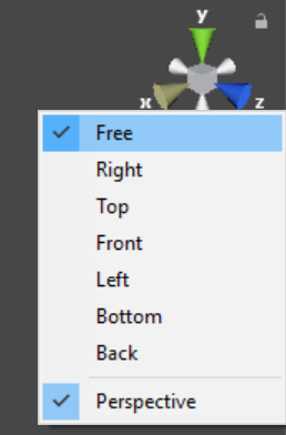
As shown in Figure 9-6, the Scene gizmo looks like a gray cube with six conical arms that extend from the middle of each side of the cube. You use the Scene gizmo to modify the viewing angle and projection mode. To change the viewing angle, click one of the conical arms. Alternatively, right-click the Scene gizmo and choose the desired viewing angle from the context menu that appears. (See Figure 9-7.) (To restore the default viewing angle, right-click the Scene gizmo and choose Free.) To switch perspective modes, right-click the Scene gizmo and uncheck the Perspective option to enable Orthographic mode (also known as Isometric) in the context menu. You can also switch perspective modes by clicking the Persp or Iso option under the Scene gizmo. (Again, see Figure 9-6.)

![]() Tip
Tip
In addition to using the Scene gizmo to change your viewing angle, you can use your mouse (or touchpad). To do so, press and hold down the Alt key as you click and drag the cursor. You can also use your mouse (or touchpad) to change the zoom, by using the scroll function. To move around the scene, you can use the keyboard arrows. Alternatively, click the Drag button in the toolbar (it features a hand icon) or press the Q key on your keyboard to use the Drag tool.
The Control Bar
The control bar, shown in Figure 9-8, includes several settings for controlling the scene preview.
The control bar includes access to the following settings:
- Draw Mode
- View, lighting, and audio
- Effects
- Gizmos
Draw Mode settings The Draw Mode settings are divided into several groups. The most important ones for our purposes are the Shading Mode, Miscellaneous, and Global Illumination groups.
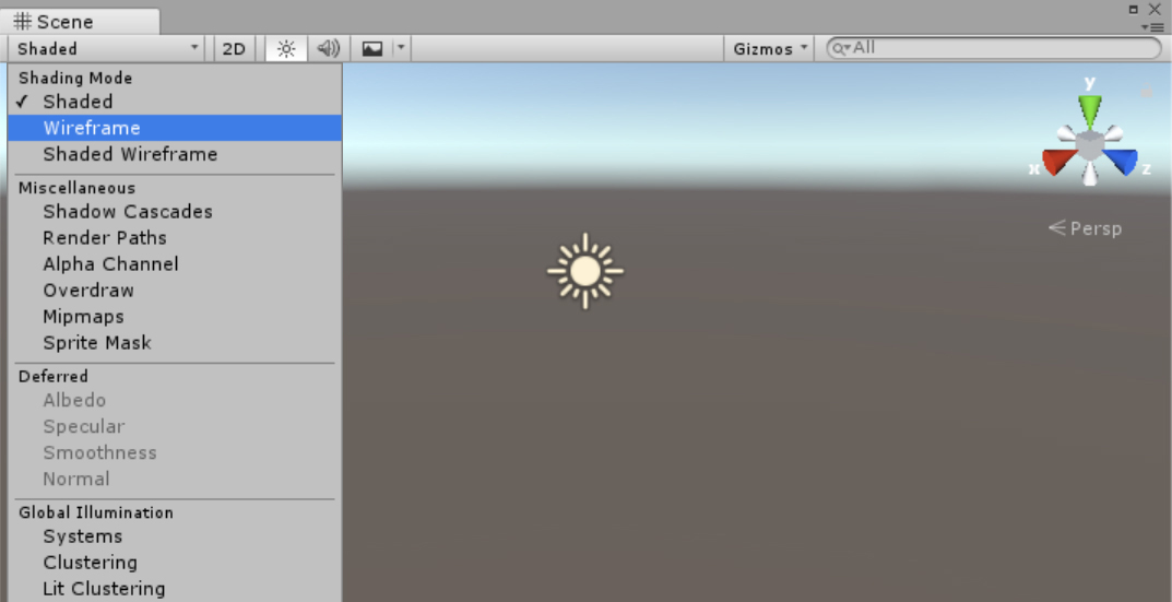
The Shading Mode group has the following options (see Figure 9-9):
- Shaded Click this option to view the surfaces and textures of the selected object.
- Wireframe Click this option to view a wireframe rendering of the selected object.
- Shaded Wireframe Click this option to view the surfaces and textures and a wireframe rendering of the selected object.

The Miscellaneous group has the following options (see Figure 9-10):
- Shadow Cascades Choose this option to display directional light shadow cascades.
- Render Paths Choose this option to show the color-encoded rendering path. Blue denotes deferred shading, green denotes deferred light, and yellow denotes forward rendering.
- Alpha Channel Choose this option to render opacity (alpha). Brighter objects have less opacity.
- Overdraw Choose this option to render transparent envelopes of scene objects. The intensity of each point in the rendered scene increases with the number of overlapping objects.
- Mipmaps Choose this option to denote color-encoded texture sizes. Blue indicates that the texture size could be larger, while red denotes that the texture size is too large.
- Sprite Mask Choose this option to display sprite masks.

The Global Illumination group provides several options to help you visualize global scene illumination, including UV Systems, Albedo, Irradiance, and Directionality. Visit http://bit.ly/GI_visualization to learn more about global illumination.
View, lighting, and audio options Next to the Draw Mode option in the control, you’ll see three buttons:
- 2D/3D This button toggles between 2D and 3D views of the scene.
- Lighting Use this button to disable or enable scene lighting.
- Audio Use this button turn on or off any audio effects.
Effects settings Click the Effects button to enable or disable the following rendering options:
- Skybox Clicking this option enables or disables rendering of the skybox texture.
- Fog Use this option to enable or disable the fog effect.
- Flares This option enables or disables the display of lens flares of light.
- Animated Materials Choose this option to enable or disable the animation of materials.
- Image Effects This option lets you enable or disable all effects at once.
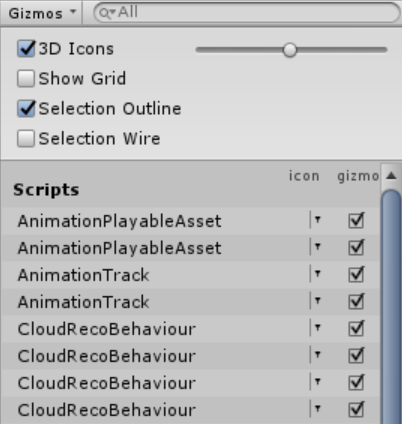
The Gizmos menu The Gizmos menu, shown in Figure 9-11, contains many additional options for controlling the rendering of objects in the scene. These options are documented here: http://bit.ly/gizmos_menu.
![]() Note
Note
Options in the Gizmos menu alter the scene preview. They do not affect the final app.
The Inspector Window
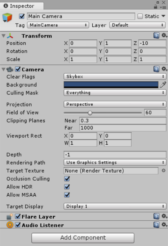
The Inspector window (sometimes simply called the Inspector) shows a list of configurable properties of the object selected in the Hierarchy window or Scene view. As an example, Figure 9-12 shows the Inspector window displaying properties of the main camera object.
The Inspector window divides properties into several groups. Different object types have different groups of properties. However, some groups apply to many objects, such as the following:
- Identity This group, located at the top of the Inspector window, includes an Object Name box; an Object Tag drop-down list; a Layer drop-down list, which you can use to associate the object with a particular scene layer; and a Static checkbox, which you can use to inform the Unity engine that the object will not move during app execution (and thereby enable Unity to optimize physics simulation to improve app performance).
- Transform This group is located right below the Identity group. You use the boxes in this group to define the object’s position in the scene as well as its rotation angle and scale along each direction. Modifying Transform properties in the Inspector is a convenient way to position and resize objects in the scene.
- Component You use this group, located on the bottom of the Inspector window, to associate components with the game object.
The Project Window
By default, the Project window contains two tabs:
- Console This tab displays warnings, errors, and other messages generated by Unity. You typically use this tab for debugging and building (to investigate eventual build errors). The Unity Console tab is like the Debug window in Visual Studio.
- Project You use this tab to display and manage assets in the current project. This tab has a pane on the left that shows a hierarchical list of all the assets and asset folders. When you choose a folder in the pane, its contents are displayed on the right. (See Figure 9-13.) You typically use the Project tab to search for assets and add them to the scene.

FIGURE 9-13 The Project tab displays a project’s assets.
![]() Note
Note
The Console and Project tabs can also be displayed as separate windows and placed wherever you like. I describe them together here because they are combined into one window in the default layout of the Unity Editor.
Creating Scenes
Now that you’ve explored the interface of the Unity Editor, you’re ready to learn how to modify a default scene created by the Unity Editor. In this section, you’ll start by reviewing primitive 3D objects with default materials. Then you’ll learn how to use more advanced objects like terrain, trees, and ragdolls. After that you’ll find out how to create and edit materials, use prefabs, and how to create a wind zone. This will give you a comprehensive overview of how to extend a default scene.
Working with 3D Objects
There are multiple ways to add a 3D object to a scene:
- By right-clicking in the Hierarchy window, choosing 3D Object in the menu that appears, and selecting the type of object you want to create from the list that appears (refer to Figure 9-5)
- By clicking the Create button in the upper-left corner of the Hierarchy window, choosing 3D Object from the menu that appears, and selecting the type of object you want to create in the menu that appears
- By opening the GameObject menu in the menu bar, choosing 3D Object, and selecting the type of object you want to create
You can create six types of primitive 3D objects—cube, sphere, capsule, cylinder, plane, and quad—as well as several complex 3D objects, including terrain, tree, ragdoll, wind zone, and 3D text.
Exploring Primitive 3D Objects
Figures 9-14 and 9-15 show examples of primitive 3D objects added to a scene.

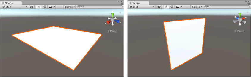
Let’s start by learning how to work with primitive 3D objects using a cube. Go ahead and add one to the scene. Afterward, your scene should look like the one in Figure 9-16—just a single solid object.

Positioning a primitive 3D object By default, this new object will be positioned at the origin of the coordinate system associated with the scene (When you change the scene preview area, new objects will be placed approximately in the center of the currently displayed region of the scene.) The coordinate system uses three component vectors (X, Y, Z) to uniquely represent object position in the scene. To check the current position of the object in the scene, you select the object (in this case, the cube) and switch to the Inspector. The Position settings in the Transform group will indicate the position: 0, 0, 0. If you change these values, the cube will be repositioned accordingly.
You can also move the object using its Move gizmo handle. A gizmo handle is a visual tool that helps you transform an object. You can see the cube’s Move gizmo handle in Figure 9-16. It features three color-coded coordinate arrows: red for the X axis, green for the Y axis, and blue for the Z axis. To use the Move gizmo handle, you drag and drop the arrow that corresponds to the desired axis. This is useful when you want to adjust an object’s position along only a single axis. During this process, the Unity Editor ensures that object translation does not reflect involuntary mouse or touchpad movements.
Rotating a primitive 3D object There are two ways to rotate a primitive 3D object:
- By modifying the Rotation properties in the Transform group in the Inspector
- By clicking the Rotate button in the toolbar (highlighted in Figure 9-17)

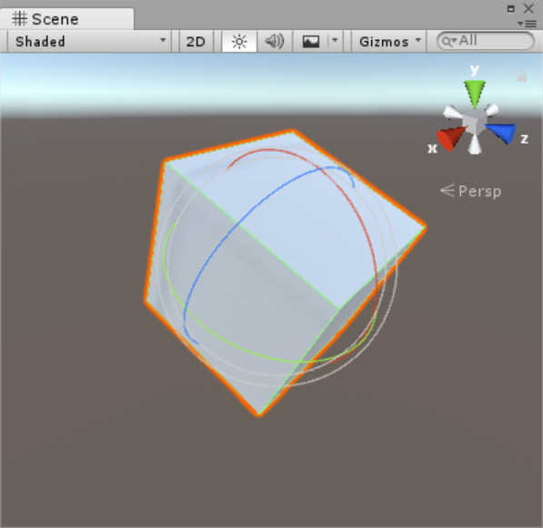
When you click the Rotate button, a Rotate gizmo handle with several spheres surrounds the selected object. (See Figure 9-18.) Like the arrows in the Move gizmo handle, the active spheres in this gizmo handle are color-coded: the red sphere corresponds to the X axis, the green sphere to the Y axis, and the blue sphere to the Z axis. Simply click the sphere representing the axis along which you want to rotate the object and drag the cursor.
![]() Note
Note
When you rotate an object, the Rotation properties in the Inspector’s Transform group display the rotation angles.
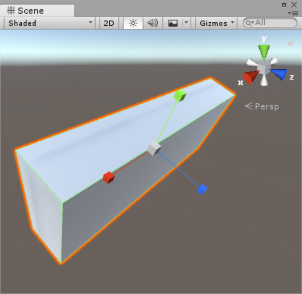
Scaling a primitive 3D object Scaling an object is very similar. You can either use the Scale properties in the Transform group of the Inspector or you can click the Scale button in the toolbar (located to the right of the Rotate button; refer to Figure 9-15). This activates the Scale gizmo handle. (See Figure 9-19.) Each scaling axis is represented by a line with a color-coded cube on one end. You click and drag a cube to scale the object along the corresponding direction. (Again, red corresponds to the X axis, green to the Y axis, and blue to the Z axis.) Again, all changes will be automatically reflected in the Scale properties of the Transform group in the Inspector.
Using the RectTransform tool The RectTransform tool combines the Move, Rotate, and Scale tools into a single gizmo. To access it, click the RectTransform button in the toolbar (the rightmost button shown in Figure 9-17). As shown in Figure 9-20, a rectangle with small blue dots in each corner and a small doughnut-shaped icon in the center will surround the selected object. Do one of the following:
- To move the object, click anywhere inside the rectangle and drag in the desired direction.
- To rotate the object, click just beyond the corner. Then, when the cursor icon changes, click and drag the icon in the desired direction.
- To scale the object, position the cursor on one corner of the rectangle (to scale along two directions simultaneously) or on an edge (to scale along a single direction). Then, when the cursor icon changes, click and drag inward or outward.

Again, all changes done with the tool will be reflected in the Transform group in the Inspector.
![]() Tip
Tip
You can also select the various transform tools using keyboard hot keys. Press W to select the Move tool, press E to select the Rotate tool, press R to select the Scale tool, and press T to select the RectTransform tool. At first, you will probably prefer to use the toolbar, but in the long run you will likely want switch to using these hot keys.
Object Parenting
You can combine primitive 3D objects to create complex 3D models. When working with such items, you often use parenting. An object’s parenting describes its location in the scene’s hierarchy. The top item is the parent, and all items below it are defined as child objects or descendants. In general, this hierarchy contains multiple levels. In the default scene you created earlier, the untitled scene was the parent of two objects: main camera and directional light. (Refer to Figure 9-5.)
Object parenting is also very helpful when you want to manipulate multiple objects at once. For instance, you can move, rotate, or scale a group of objects simultaneously rather than adjusting the properties of each individual object independently.
To make one object (let’s call it object A) the descendant of another object (object B), you use the Hierarchy window. Simply click object A and drag it to object B. When you release the mouse button, object B will become the parent of object A. From now on, any transformations you make to the parent will also apply to its descendants.
Let’s see how this works in practice. Follow these steps:
- Remove the cube object from the scene by right-clicking it in the Hierarchy and choosing Delete from the menu that appears.
- Add a new cube, a cylinder, and a sphere. Make sure all of them are positioned at the origin (0, 0, 0).
- Click the cube to select it. Then, in the Scale properties in the Transform group of the Inspector, change the X setting to 1.5, the Y setting to 0.1, and the Z setting to 1.5.
- Click the sphere to select it. Then, in the Position properties in the Transform group of the Inspector, change the Y setting to 1.
- Leave the cylinder transform unchanged. Then, in the Hierarchy, drag the cylinder and sphere objects to the cube.
- Right-click in the Hierarchy, choose Save Scene As, and set the scene name to MyScene. Your saved scene should look like the one shown in Figure 9-21.
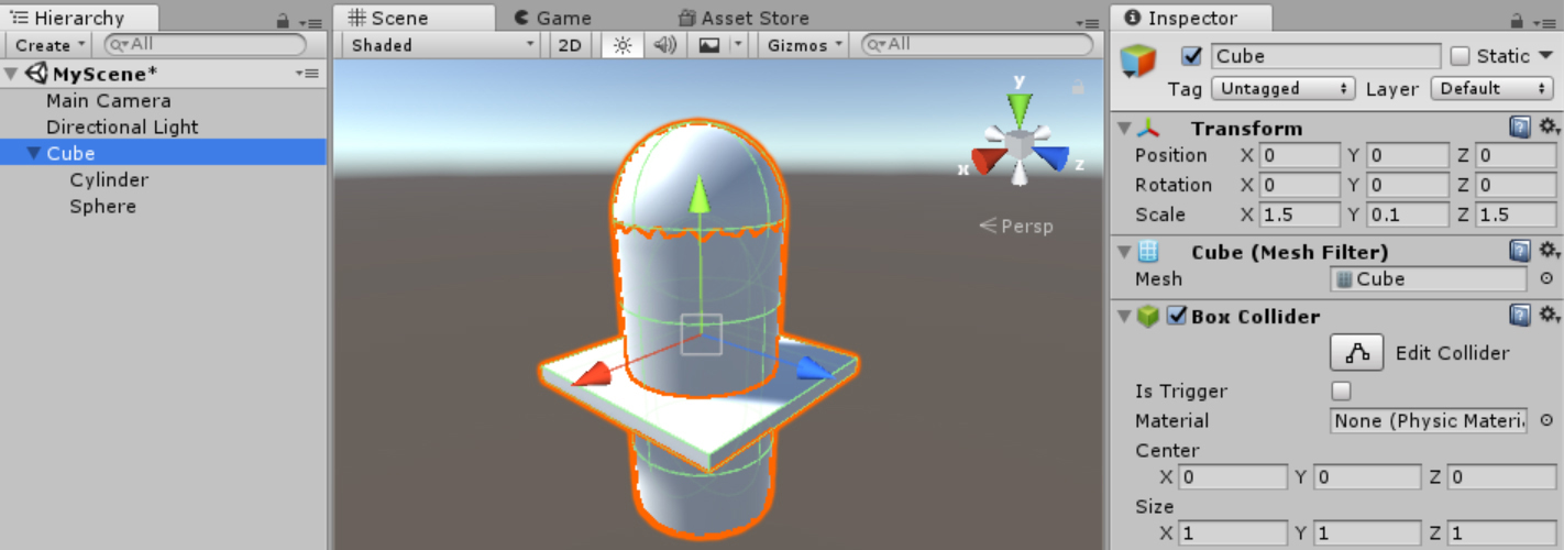
FIGURE 9-21 An object created from a cube, a cylinder, and a sphere.
With this scene, whenever you select the cube, all its descendants will be also become active. So, you can transform them together using the Scene view and the toolbar or by manually changing the Transform group properties in the Inspector. To transform a descendant object independently, select it in the Hierarchy. Any changes you make to it will not apply to the parent or to any other objects on the same hierarchy level.
Applying Terrain
You can use terrain—or more precisely, the terrain engine—to develop landscapes in a scene. You add terrain in the same way as you add primitive 3D objects: via the Hierarchy window context menu or the 3D Object submenu of the GameObject menu.
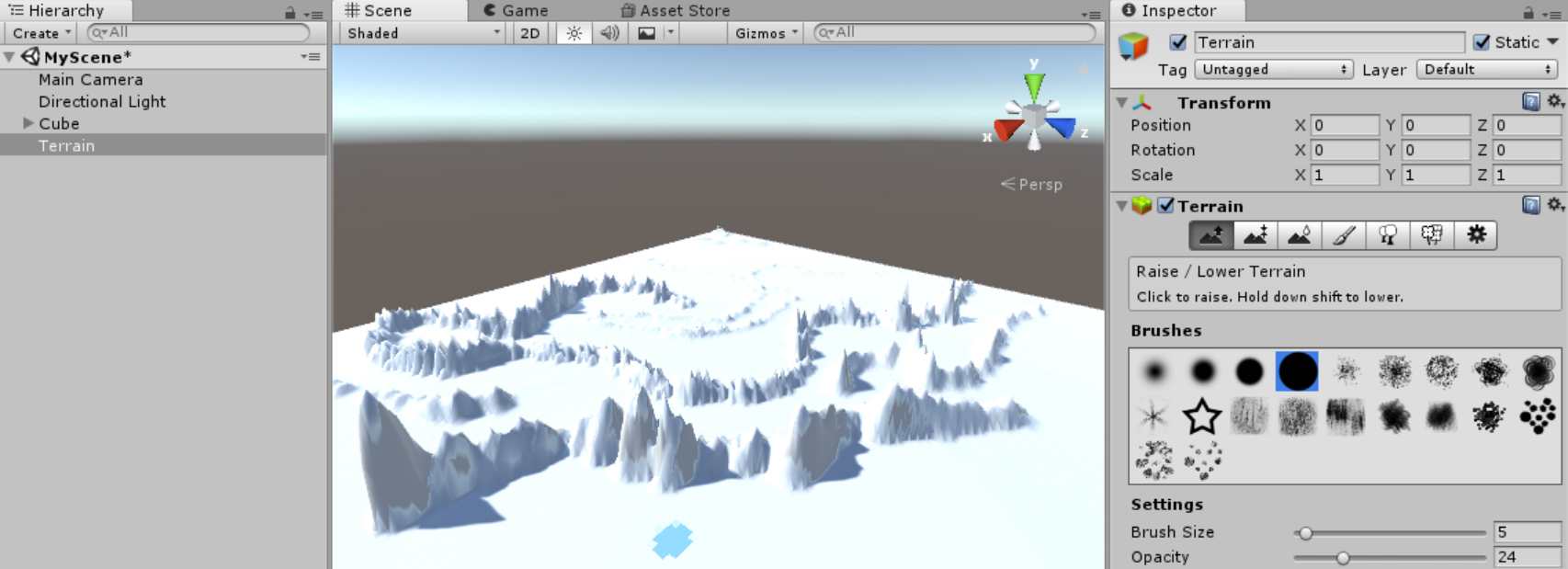
After you add terrain to a scene, you can use brushes that appear in the Inspector to draw landscape elements. (See Figure 9-22.) Here’s how:
- Terrain occupies a lot of space in a scene, so start by reducing the zoom.
- In the Inspector, choose the brush you want to use and adjust its settings as desired.
- In Scene view, drag the cursor along three dimensions to create or more precisely draw the landscape.
You can quickly define the entire landscape for your app. Note, however, that you use terrains only to build virtual reality (VR) experiences. In augmented reality (AR) applications, the terrain, or landscape, is composed of real objects (trees, mountains, lakes, and so on), so it is not necessary to make virtual terrain. (For more info on creating terrains, see http://bit.ly/terrain_engine.)
Adding Trees
You add a tree to a scene the same way you add any other 3D object. When you do, the tree will open in the Tree Editor. At first, the tree will have a single branch. (See Figure 9-23.)

To create new branches and leaves, you edit the tree hierarchy using the Tree group in the Inspector. (Refer to Figure 9-23.) As shown in Figure 9-24, the tree hierarchy in the Tree group contains two elements by default: a Tree Root node (bottom icon) and a Branch Group (top icon). The Tree group also contains four buttons in the bottom-right corner. From left to right these are the Add Leaf Group button, the Add Branch Group button, the Copy button, and the Delete button.

![]() Tip
Tip
Your tree will be added to your project’s assets—meaning you can reuse it. You’ll learn how to do this later in this chapter.
To add a new branch to the tree, follow these steps:
- Click the Branch Group node.
- Click the Add Branch Group button. The new branch is created.
- To modify the branch to make it look more realistic, experiment with the Distribution, Geometry, and Shape parameters in the Inspector. (See Figure 9-25).
- Add more branches as you see fit.

FIGURE 9-25 Modifying the tree branch.
To add leaves to the tree, follow these steps:
- Click the branch to which you want to add leaves. (In this example, I selected the top branch.)
- Click the Add Leaf Group button. (Refer to Figure 9-24.)
- At first, the leaves will appear as rectangular planes. (See Figure 9-26.) For them to look like actual leaves, you’ll need to apply a material to them. (You’ll learn how to add materials to leaves later in this chapter.) For now, in the Inspector, increase the value for the Frequency parameter in the Distribution group to add more leaves.
- Experiment with the other leaf properties. (For more on these properties, see http://bit.ly/tree_editor.)
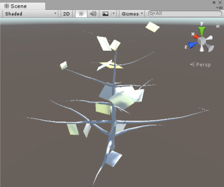
FIGURE 9-26 A tree generated in the Tree Editor.
Adding 3D Text
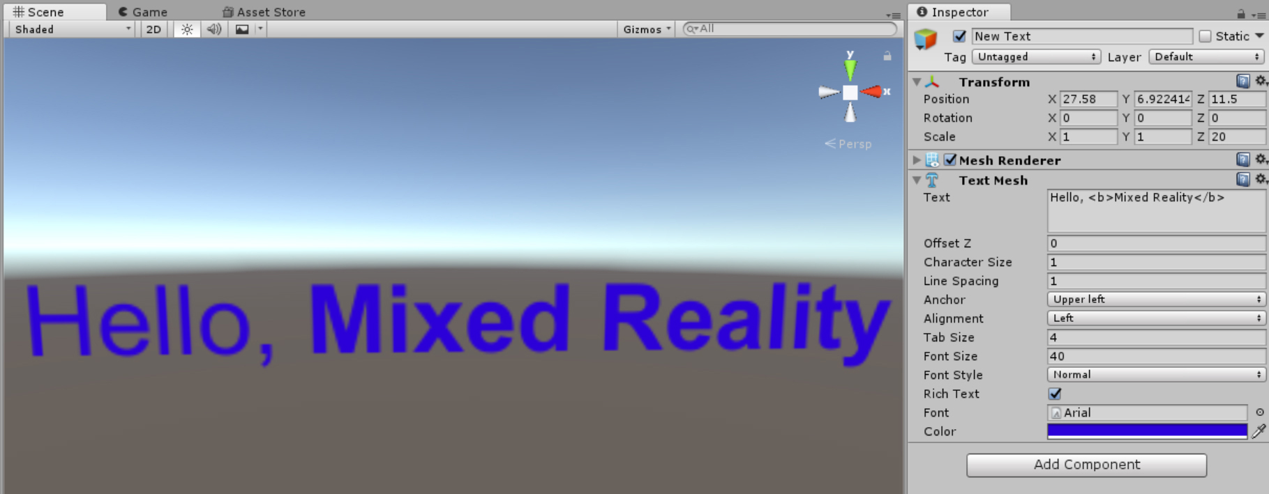
The 3D text object displays strings of letters, numbers, or symbols. This string can appear on a single line or can be multi-line. After you add a 3D text object to the scene—which you do in the same way you add any other type of object—you can change its appearance by modifying its parameters in the Inspector. Options include the following:
- Text This is where you enter the text to be displayed in the 3D text object. Provided the Rich Text checkbox is selected, the rendering engine will format your string based on the following tags:
- <b>...</b> These tags format the 3D text object with a bold font. For example, the string
<b>Mixed Reality</b>results in a 3D text object with the text Mixed Reality in bold font. - <i>...</i> These tags format the 3D text object with an italic font. For example, the string
<i>Hello, World!</i>results in a 3D text object with the text Hello, World! in italic font. - <size=x>...</size> These tags set the font size to x pixels. For example, the string
<size=45>Big Text</size>results in a 3D text object with the text Big Text set to 45 pixels. - <color=#rrggbbaa>...</color> or <color=color_name>...</color> These tags set the font color to the given hexadecimal code or color name. For example, the strings
<color=#ff0000ff>Red</color>and<color=red>Red</color>both produce the same result: a 3D object containing the word Red in red text.
- <b>...</b> These tags format the 3D text object with a bold font. For example, the string
- OffsetZ This parameter indicates the distance from the origin of the Z axis that the text should be rendered.
- Character Size This parameter sets the size of each character.
- Line Spacing This parameter sets the spacing between each line.
- Anchor This parameter marks the beginning point of the transform. If you change the value for this parameter, the transform properties (position, rotation, and scale) will start from the new point.
- Alignment This parameter sets the text alignment.
- Tab Size This parameter sets the size of the text indent in the 3D text object. (To create an indent, type .)
- Font, Font Size, Font Style, and Color These parameters specify the font, font size, font style, and font color. You can use these instead of tags to change the appearance of your text.
Figure 9-27 shows the result of a 3D text object with the text Hello, Mixed Reality, in which the bold font was set using tags (as described in the Text bullet in the preceding list) and the text color and size were defined using the corresponding properties in the Inspector.
Adding a Ragdoll
A ragdoll is a tool that automatically implements the physics needed to make a character move and interact with objects in a scene in a realistic manner. Before you can create a ragdoll, you need to assemble the various elements that will constitute its body, including its feet, legs, hips, pelvis, arms, elbows, hands, head, and spine. You can model these objects in 3D software to include skinned meshes. This is time-consuming, however. To speed things up, this chapter uses the Ethan character included in the character package of standard Unity assets.
To import the character package and extract the Ethan character, follow these steps:
- Open the Assets menu, choose Import Package, and select Characters. The Import Unity Package window opens, showing a list of included assets.
- Click the All button to select all the assets.
- Click the Import button.
- When the import operation is finished, the Project window appears. Open the Assets/Standard Assets/Characters/ThirdPersonCharacter/Models folder, as shown in Figure 9-28. (Alternatively, type Ethan in the search box.) Then click the Ethan item and drag it to the Scene view. (Click OK in any dialog boxes that appear.)
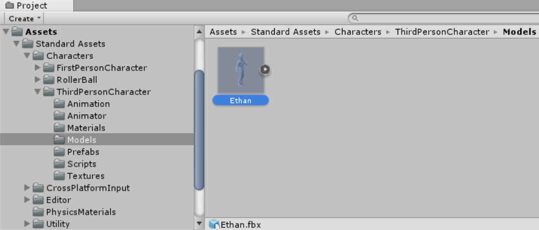
FIGURE 9-28 The Project window showing the Ethan model.
Next, you’ll add a plane and several objects to the scene, including the Ethan character, a tree, and some 3D text. First, make sure your tool handles are in Global mode—that is, with the gizmo toggles set to Center and Local. After you add the objects, set the Position and Rotation parameters in the Inspector’s Transform group as described in Table 9-1.
Table 9-1 Position and Rotation Parameter Settings
Object |
Position parameter setting |
Rotation parameter setting |
|---|---|---|
Plane |
X: 0 Y: −1 Z: 1 |
X: 0.6 Y: −1 Z: 1 |
Ethan |
X: 0 Y: 3 Z: −0.1 |
X: 0 Y: 180 Z: 0 |
Tree |
X: 10 Y: −2 Z: 10 |
X: 0 Y: 0 Z: 0 |
3D text |
X: −20 Y: −1 Z: 25 |
X: 0 Y: −45 Z: 0 |
Main camera |
X: 0 Y: 3 Z: −7 |
X: 15 Y: 0 Z: 0 |
Directional light |
X: 0 Y: 3 Z: 0 |
X: 50 Y: −30 Z: 1 |
To gain a better understanding of the ragdoll, click the Play button in the toolbar. You’ll see the Ethan character positioned above some 3D text, a tree, a cube and its descendants (which compose the object you created earlier; refer to Figure 9-21), and the plane, as shown in Figure 9-29.

Notice that even in Play mode, the Ethan character does not move. This is because you have not yet applied a ragdoll object to the Ethan character. You’ll do that next.
- Click the Start button to exit Play mode.
- Expand the Ethan object in Hierarchy window to display its child items. (See the left screen in Figure 9-30.) Make sure all other objects in the window are deselected.
- Right-click in the Hierarchy, choose 3D Object from the menu that appears, and select Ragdoll to open the Ragdoll Creator. (See the right screen in Figure 9-30.)
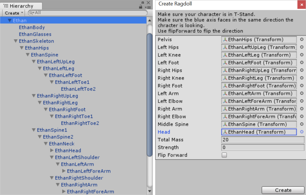
FIGURE 9-30 Ethan’s hierarchy (left) and ragdoll configuration (right). - You’ll use the Ragdoll Creator to associate Ethan’s child items with the corresponding ragdoll items as follows. (Leave any other settings at their default values.) To associate a child item with a ragdoll item, you drag it from the Hierarchy to the corresponding box in the Ragdoll Creator.
- Pelvis EthanHips
- Left Hips EthanLeftUpLeg
- Left Knee EthanLeftLeg
- Left Foot EthanLeftFoot
- Right Hips EthanRightUpLeg
- Right Knee EthanRightLeg
- Left Arm EthanLeftArm
- Left Elbow EthanLeftForeArm
- Right Arm EthanRightArm
- Right Elbow EthanRightForeArm
- Middle Spine EthanSpine
- Head EthanHead
- Click the Create button.
- Click the Start button in the toolbar to run the app again. This time, when the app starts, Ethan will begin to fall (see Figure 9-31) until he finally lands on the plane (see Figure 9-32). Note that his movement appears very realistic because he bounces off of all obstacles.
- Change Ethan’s initial position. Notice that his movement changes accordingly.
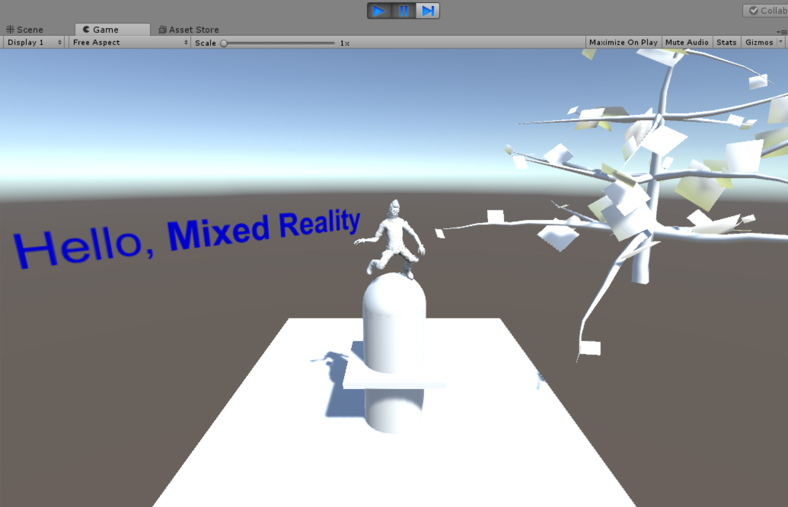
FIGURE 9-31 The Ethan ragdoll hits the custom 3D object. 
FIGURE 9-32 The Ethan ragdoll falls on the plane.
Using Materials
So far, you’ve created several 3D objects. However, all these objects—except the 3D text object—are the same color. This is because they all use their default material. You can apply a different material to an object to change how its surfaces are rendered.
Let’s explore materials by creating some to apply to the leaves on the tree object you assembled earlier in this chapter. To start, you need to import the appropriate textures for these materials into Unity. In this example you’ll use textures from the environment package in the standard Unity assets. To import this package, open the Assets menu, choose Import Package, and select Environment. Then import all elements from that package.
Your next step is to create the materials. Here’s how:
- Create a new folder for the materials you are about to create. To do so, open the Project window and right-click the Assets folder. Then, in the menu that appears, choose the Create option and select Folder.
- Name the new folder Custom Materials.
- Click the Custom Materials folder to select it.
- Open the Assets menu, choose Create, and select Material. This adds a new material to the Custom Materials folder.
- Name the new material LeavesMaterial.
- In the Inspector for the LeavesMaterial material, open the Shader drop-down list, and choose Nature/Tree Creator Leaves Fast.
- In the Inspector, click the Select button on the texture slot (highlighted in blue) to open a Select Texture window. (See Figure 9-33.)

FIGURE 9-33 Creating a material for leaves using the Inspector for the material (left) and the Select Texture options (right). - In the Select Texture window, select the leaf texture you want to use. (I chose Broadleaf_Mobile_Atlas.)
- Drag and drop the LeavesMaterial material onto your tree in the Scene view.
- Optionally, adjust the number of leaves according to your preferences.
To make your tree look even more realistic, you can create a material for the bark. Follow these steps:
- Select the Assets/Custom Materials folder in the Project window.
- Open the Assets menu, choose Create, and select Material to create new material.
- Name the new material BarkMaterial.
- In the material’s Inspector, change the Shader setting to Nature/Tree Creator Bark.
- Select a base texture for the material. (I chose ConiferBark.)
- Drag and drop the BarkMaterial material on the tree branches in the Scene view. Figure 9-34 shows the final version of my tree.
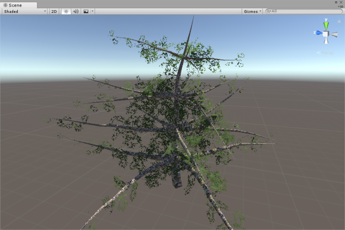
FIGURE 9-34 A tree with materials applied.
Your scene is starting to look pretty good. Let’s make it even prettier by applying materials to other objects as follows:
- Change the plane object to look like the ground. To do so, create a new material named GroundMaterial, change its Shader setting to Unlit/Texture, set its texture to GrassRockyAlbedo, and apply it to the plane.
- Add a new material for your custom object (made from a cylinder, cube, and sphere) and name it ObstacleMaterial. Change its Shader setting to Unlit/Texture, set its texture to MudRockyAlbedoSpecular, and apply it to all elements composing the custom object.
- Modify the material already applied to Ethan to change its color. To do so, open the Project window and type EthanWhite in the search box. Unity filters the list of assets to display only one. Click this item, switch to its Inspector, click the color box next to the Albedo setting, and choose any color you like from the color picker that appears. I’ve made Ethan cyan. (See Figure 9-35.)
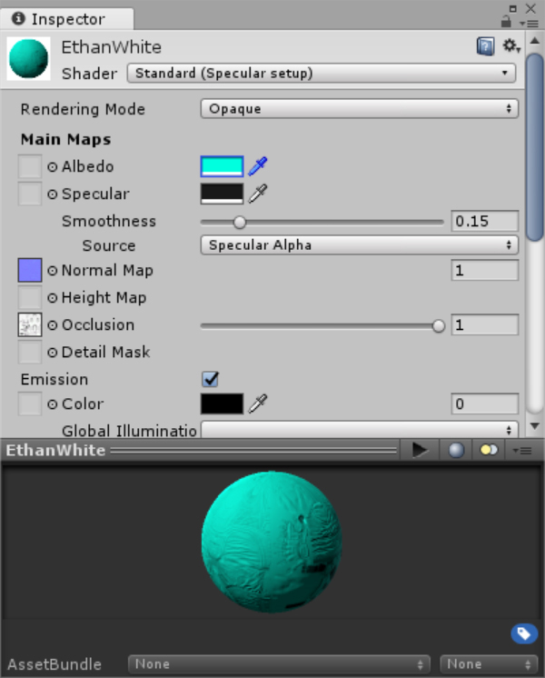
FIGURE 9-35 Properties of the modified Ethan material.
Applying Prefabs
Now that you’ve learned how to create and edit materials, let’s investigate how to quickly reuse custom objects using prefabs. Unity defines prefab as a game object with associated components and properties. A tree, like the one you created earlier, is a good example of an object that can be converted into a prefab that you can use to quickly create a little forest. Here’s how to do it:
- In the Project window, open the Assets folder and create a new folder inside it called Custom Prefabs.
- Open the Custom Prefabs folder.
- Open the Assets menu, choose Create, and select Prefab to create a new prefab. It will appear under the Assets in the Project window.
- Name the new prefab Tree Prefab.
- Drag the tree object from the Hierarchy onto the Tree Prefab in the Project window. The prefab icon will change to show a miniature of the tree.
- Drag the two instances of the new prefab from the Project window into the scene. The scene should now contain three trees.
- Change the Position setting for the two new trees as follows:
- X: 8, Y: 0, Z: 1
- X: 2, Y: 0, Z: 7
- Extend the plane so it will look like a larger area of ground. To do so, set the plane’s Scale setting to X: 5, Y: 5, Z: 5.
Adding a Wind Zone
To make the scene even more exciting, try adding a wind zone. A wind zone is an object that makes trees sway in a realistic manner in the wind. (For more information, see http://bit.ly/wind_zone.) To see how the wind zone works, add one to your scene, just as you would any other object.
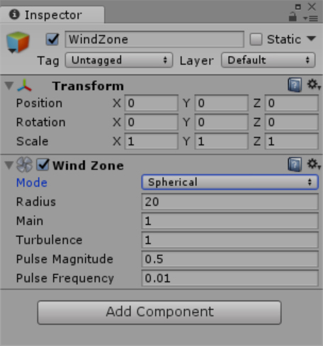
After you add the wind zone object to your scene, you can use the Inspector to set various parameters. (See Figure 9-36.) One such parameter is Mode, which enables you to set the wind mode. Options include the following:
- Directional Choose this if you want the wind to appear to blow in a single direction.
- Spherical Select this if you want the wind to appear to blow inside the sphere of a given radius (set via the Radius parameter).
You can also set the wind strength using the following parameters:
- Main This setting refers to the primary wind force, which changes slowly over time.
- Turbulence This setting creates a wind force that changes rapidly.
- Pulse Magnitude You use this setting to specify the amplitude of wind changes over time. The larger the value here, the more the trees sway.
- Pulse Frequency This setting determines the frequency of wind changes over time. The smaller the frequency, the faster the trees will sway.
![]() Tip
Tip
Try experimenting with these parameters and adjusting them to your needs. To see real-time updates of the wind parameters, click the Start button to enter preview mode. Then use the Inspector to modify parameters and see how they affect the way your trees sway.
Building and Deploying the Project
With your scene ready, you can now build your project, UnityBasics, and deploy it to a Windows Mixed Reality device—either the HoloLens emulator or a Windows Mixed Reality headset. In general, the build process involves two steps. First, you build the project in the Unity. This creates a Visual Studio solution. Then, you compile this solution and deploy to the selected target device. With the use of some additional tools, discussed later in this chapter, you can simplify this general build process.
Building the Project
To build a project in Unity, open the File menu and choose Build Settings or press the Ctrl+Shift+B keyboard shortcut to open the Build Settings window. (See Figure 9-37.) Then, in the Build Settings window, follow these steps:
- Click the Add Open Scenes button. This ensures your scene will be included in the build.
- In the Platform list, click Universal Windows Platform. Then click the Switch Platform button to change the current platform to UWP.
- Ensure that the Build Type drop-down list is set to D3D.
- Ensure that the SDK drop-down list is set to Latest Installed.
- Click the Player Settings button to open the PlayerSettings Inspector window. (See Figure 9-38.)
- Click the Other Settings option to expand it and, in the Configuration group, click the Scripting Backend drop-down list. The scripting backend is a framework you use to implement logic. When developing for UWP, you can choose from two scripting backends:
- .NET This uses the Microsoft .NET Framework and produces the Visual C# UWP project.
- IL2CPP This extends the capabilities of the .NET scripting backend. IL2CPP converts the IL code into C++ code. So, it produces the Visual C++ UWP project.
In this case, choose the .NET option. (See the left screen in Figure 9-38.)
- Click the XR Settings option to expand it and select the Virtual Reality Supported checkbox.
 Note
NoteXR stands for X Reality. This is a slightly more general term than Mixed Reality (MR). XR includes all technologies, both hardware and software, that enable the creation of VR, AR, and MR experiences. Sometimes XR is defined as an umbrella term for VR, AR, and MR.
- Make sure the Virtual Reality SDKs list contains a Windows Mixed Reality entry. If not, click the plus button and choose Windows Mixed Reality to add it. (See the right screen in Figure 9-38.) The Windows Mixed Reality SDK enables a stereoscopic preview and head tracking. In other words, you do not need to implement stereoscopy or head tracking separately.
- Click the Build button in the Build Settings window.
- Select a folder to contain the build—for example, the UnityBasicsBuild folder—and click Select Folder. The build process starts. The app may take a while to build.


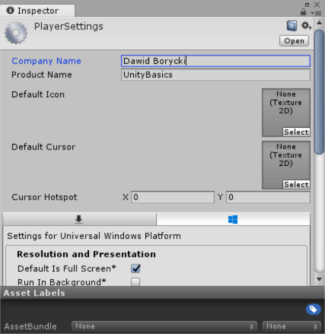
The PlayerSettings Inspector window enables you to configure many more app details. Specifically, you can set the company and product name, default icon, splash screen, app capabilities, and so on. (See Figure 9-39.)
Deploying to Immersive Headsets
After the project is built, you can deploy it to the target device. When deploying to immersive headsets, you have two options for executing the app:
- Click the Play button in the Unity Editor. This will open the Windows Mixed Reality portal where, after a short while, your app will be executed.
- Open the Visual Studio solution generated by Unity, change the target platform to either x86 or x64, and set the target device to the local machine. Then proceed in the same way as when you deployed 2D apps—by opening the app through the Windows Mixed Reality portal.
Regardless of which method you choose, the result will be the same. (See Figure 9-40.)

Deploying to a HoloLens
You use Visual Studio to deploy to a HoloLens emulator. First, change the platform to x86 and then choose HoloLens Emulator from the drop-down list. Then build and run the app. The app will be executed in the emulator. (See Figure 9-41.)

Unity generates a Visual C# UWP project, so you can easily deploy the app to any other UWP device. Figure 9-42 shows the UnityBasics app running in the Mobile emulator.

When you run the app in the HoloLens emulator, you will notice two issues related to the default camera settings:
- The default skybox is visible and will hide real objects if the app is executed in a real device with see-through display (HoloLens).
- The field of view is much smaller than with the immersive headset simulator, so you can only see a small part of the scene. To see more elements of the scene, press the D key on the keyboard to move the viewer back.
To address the first issue, you change the following camera settings in the Inspector. (See Figure 9-43.)
- Change the Clear Flags setting to Solid Color.
- Click the Background color option to open a color picker and set all the color components (R, G, B, and A) to 0.

![]() Note
Note
You’ll learn how solve the second issue, related to FoV, later in this chapter.
Using Holographic Emulation
You can adjust the camera position iteratively, but this is time-consuming and inefficient. Instead, use holographic simulation, part of the Unity Editor’s holographic emulation feature. Holographic emulation reduces the iterative build process for HoloLens because it enables you to preview your app directly in the Unity Editor or to automatically deploy it to real a device. (For more information, see http://bit.ly/holographic_emulation.) When you click the Play button, the app is executed in the Game view (holographic simulation) or in the real device (holographic remoting).
To enable and employ holographic emulation, follow these steps:
- Open the Window menu in the Unity menu bar and choose Holographic Emulation to open the Holographic window.
- The Holographic window contains an Emulation Mode setting. (See Figure 9-44.) The options for this setting are as follows. (Note that when you choose an option for the Emulation Mode setting other than None, the Holographic window changes to include additional parameters.)
- None Select this option to disable holographic emulation.
- Remote to Device When you choose this option, the app will be executed in the HoloLens device. To enable this mode, you must install and run Remoting Player on the headset. (For more information, see http://bit.ly/remoting_player.) Then, in the Holographic Emulation window, enter the IP for your device and click the Connect button.
- Simulate in Editor When you choose this option, the app will be executed in the Unity Editor in the same way as in the HoloLens emulator. To configure this mode, choose one of the available rooms from the Room list and select the Right Hand option for the Gesture Hand setting. The Room list enables you to choose one of the available spatial mapping meshes (see Chapter 12 for more details), while the Gesture Hand setting lets you define which hand is used to simulate air gestures.
- Choose Simulate in Editor.
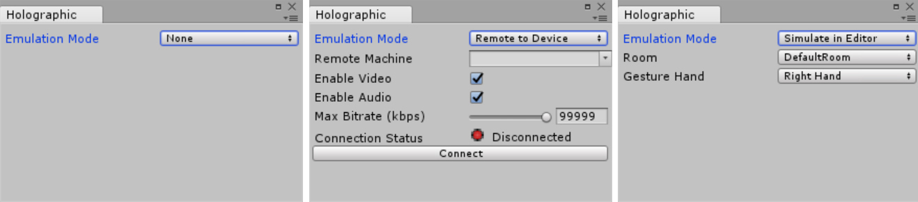
FIGURE 9-44 Configuring holographic emulation in Unity. - To use holographic simulation to view the app, click the Play button. The Game view will show a preview of the app. Notice that the time it takes to display the app is much less than when deploying an app through Visual Studio.
You can now use this mode to investigate what happens to the camera settings when the app is executed in holographic simulation mode. Follow these steps:
- Stop the preview mode.
- Click the Main Camera entry in the Hierarchy.
- After ensuring that the Inspector shows the properties of the main camera object, click the Play button. Notice that several camera properties, including Transform and Field of View, change during the runtime. Specifically, the Field of View value is reduced from 60 to 17.
- Stop the preview mode and change the value for the Field of View setting to 17.
- Adjust the Transform value. After a bit of trial and error, I settled on the following parameters:
- Position X: 4.5, Y: 6, Z: –20
- Rotation X: 15, Y: –12, Z: 0
- Rebuild the app in Unity and rerun it in the HoloLens simulator through Visual Studio. (You will need to reload the solution.) Notice that the initial view now shows more elements of the scene. (Refer to Figure 9-1.)
Mixed Reality Toolkit for Unity
Chapter 2 introduced the Mixed Reality Toolkit. This chapter shows you how to install it in Unity. You’ll use this toolkit in the chapters that follow.
To install the Mixed Reality Toolkit for Unity, follow these steps:
- Download the toolkit package from http://bit.ly/mrtk_release. At the time of this writing, the current version of this package was HoloToolkit-Unity-2017.2.1.4. (It is attached to the companion code in the Chapter_09/MixedRealityToolkit folder.)
- In Unity, open the Assets menu, choose Import Package, and select Custom Package.
- Select the package you just downloaded for import.
- The Import Unity Package window opens. Unity parses the package and displays a list of its components in the window. (See Figure 9-45.) Make sure all the components are selected and then click the Import button. When the package is imported, the Mixed Reality Toolkit for Unity will be ready for use in your projects.

FIGURE 9-45 Installing the Mixed Reality Toolkit for Unity.
3D Models
Unity lets you import 3D models created with various modeling software, including the following:
- 3D Builder
- 3D Studio Max
- Blender
- Maya
- Cinema 4D
- 3ds Max
- Cheetah3D
- Modo
- Lightwave
- SketchUp
You can also import models from various online repositories. This section shows you how to import 3D models from a 3D Builder library of models provided by Microsoft and from CGtrader.com.
To import models from the 3D Builder library, follow these steps:
- Create a new Unity project named ExternalModels.
- Open the 3D Builder library of models, available at http://bit.ly/3DBuilder_models.
- Select and download any model you like. (I chose the Shuttle model, from the featured group.)
- You cannot import the downloaded file, which has a .3mf file extension, directly to Unity. Before you can import it, you use 3D Builder to save the file with an .obj extension. To do so, open the file in 3D Builder. Then click the File menu (it looks like a hamburger) and choose Save As.
- The Save As dialog box opens; choose a folder in which to store your file and change the Save as Type setting to OBJ Format. Then click Save.
- Now you can import the model into Unity. In the Unity Editor, open the Assets menu, choose Import New Asset, locate and select the model (with the .obj extension), and click Import. Unity adds the model to the assets of whatever project you have open.
- Drag the model into the Scene view. (See Figure 9-46.)

FIGURE 9-46 A 3D Builder model imported to the Unity scene.
To import models from CGtrader.com, you must first sign up for an account with the site. You can do so here: http://bit.ly/cgtrader_registration. CGtrader.com provides models in several different formats, including 3D Studio Max, Autodesk FBX, and OBJ. If you select the OBJ format, you can import the model directly into Unity and add it to the scene as you did in steps 6 and 7 in the preceding numbered list. To import and work with one of these models, follow these steps:
- Decide which model you want to import. I chose the SciFiFighter model (http://bit.ly/SciFiFighter_model).
- Click the Free Download button.
- If prompted, sign in to your account. After you do, the download process will begin.
- The downloaded file will be an RAR archive, containing a model (OBJ file) and textures (three JPEG files). Import all these files to Unity as assets.
- Add the model to the scene as you would any other object.
- Use the Unlit/Texture shader to create the materials. Your model should be similar to that shown in Figure 9-47.

FIGURE 9-47 A SciFiFighter model imported from CGTrader.com.
Summary
This chapter discussed using Unity to create 3D scenes for Windows Mixed Reality apps. You learned about fundamental Unity concepts and elements, including game objects, components, transforms, and primitive and complex 3D objects. Then you investigated how to control the visual appearance of the objects in a scene by using materials and how to apply ragdoll physical effects to a character so it can move. This chapter also covered the deployment of 3D apps to a HoloLens emulator and an immersive headset simulator. Finally, it presented approaches for importing complex models created in 3D modeling software. In the next chapter, you will learn how to write scripts and manually implement physics to make your scenes dynamic.