
Chapter 16
Taking Control of Your Pi’s Circuitry
IN THIS CHAPTER
![]() Learning what GPIO pins you can use
Learning what GPIO pins you can use
![]() Seeing how you can control GPIO pins in Scratch and Python
Seeing how you can control GPIO pins in Scratch and Python
![]() Making a GPIO pin flash an LED and read a push button
Making a GPIO pin flash an LED and read a push button
![]() Building a working electronic dice display
Building a working electronic dice display
![]() Building a working model of a pedestrian crossing
Building a working model of a pedestrian crossing
Chapter 15 tells you all about what GPIO pins are, but in this chapter we want to describe how to access them physically and how to control them with software. We use both Scratch and Python to do this, but ultimately Python is the much more capable language for input/output control.
Accessing Raspberry Pi’s GPIO Pins
The GPIO pins are the key to enabling the Raspberry Pi to take control of any external circuit. They can be used as an output to switch on an LED or as an input to sense the state of an external push button. These connections into the computer, along with the fixed voltage power pins, are on a dual-row, 40-pin header plug. There are many ways to physically access these pins, and often the least expensive way isn’t always the easiest or the most convenient way. But what you need to know first is which signals are on which pins. A top-down view of the pins and their signals is shown in Figure 16-1.

FIGURE 16-1: GPIO header pins and their function.
There are two ways to label the pins. Figure 16-1 shows what is known as BCM mode, which corresponds to the numbers used in the Broadcom data sheet that defines the hardware. Another system was used in the early days — the BOARD system — but it is falling out of favor now. BOARD referred to pins mainly by a mixture of special function names and arbitrarily assigned “free” GPIO pin names. The idea was that, as the pinout (what connections are on what pins) on the header changed, the names could remain constant.
As it was, only the first issue of the Pi had a different pinout to all the rest, and those were only for three pins. These are shown in Figure 16-1, on the left side. Model 1 before the B+ had only 26 pins, whereas all subsequent models have 40 pins. You cannot buy the earlier models nowadays, so you have no need to worry; the extra information is only given in case you have an older Pi.
Now, it can be quite daunting to have to identify a single pin on a 40-pin header to connect to it, so you can get or make a template to place over the pins that labels them with their names. Figure 16-2 shows one of these templates in action.

FIGURE 16-2: GPIO template identifying the pins.
This particular template is made of a thin, printed circuit board material that can sit over the pins as you connect to them. We highly recommend this type if you’re going for the option of individual wires to the GPIO pins. You can also find full-scale drawings online, so you can print one out on paper and just push the pins through. Or stick the paper on thick cardboard, and drill holes through for the pins.
 When making your own template, do not use any conducting material, like aluminum.
Soldering the GPIO pins onto Pi Zero
The Pi Zero has exactly the same GPIO pins as all the other models of the Raspberry Pi, but the challenge is that the 40-way pin header doesn’t come prefitted. To use the GPIO pins, therefore, you need to buy and fit the header pins. This presents an opportunity for you because it allows you to have a header socket here instead of pins, if you want — or, in fact, any other style of connector. You could even solder wires directly into these pins, if you want to build the Pi zero permanently into a system.
 What you should not do is attempt to use these holes by simply pushing wires into them. This is an unreliable way of getting a connection that inevitably leads to damaging your Pi.
Normally, this process would involve soldering, which some people might find off-putting, so the people at Pimoroni have come up with a solution involving a compression eyelet header and a hammer. See https://shop.pimoroni.com/products/gpio-hammer-header.
However, a header isn’t too difficult to solder up yourself with a fine-tipped hot iron. Though we cover soldering in general in Chapter 15, here are some extra tips about soldering on a header strip. Push the header sockets into the holes and turn the board upside down so that it rests on the pins. Use a large lump of blue tack to make everything level and stable. Place an iron so that its tip touches both the pin and the printed circuit board hole, and then apply a little solder. You should see the solder flow round the hole. Keep the iron in place and after a half a second or so, you’ll see the solder sucked into the hole by the capillary action of the hole and molten solder. When you see that happen, remove the iron. Don't move the joint until it cools. If the solder isn’t pulled in, you either have too much solder, your soldering iron isn’t hot enough.
Now, before you solder another pin, ensure that the whole header strip is lying flat on the board. If it isn’t, melt the joint again, and push the header strip flat. (Remember: You can't correct a crooked connector after more than one pin has been soldered.) Then proceed and solder the other joints.
 If you have trouble with later joints, it’s probably because your soldering iron has cooled a bit after making a joint. If so, allow a few seconds between joints for it to warm up again. Wipe the iron on a damp sponge after each joint, to remove any flux.
Though this all sounds complex when written down this way, in practice it’s much easier and quicker. Figure 16-3 shows a close-up of a header in the process of being soldered.
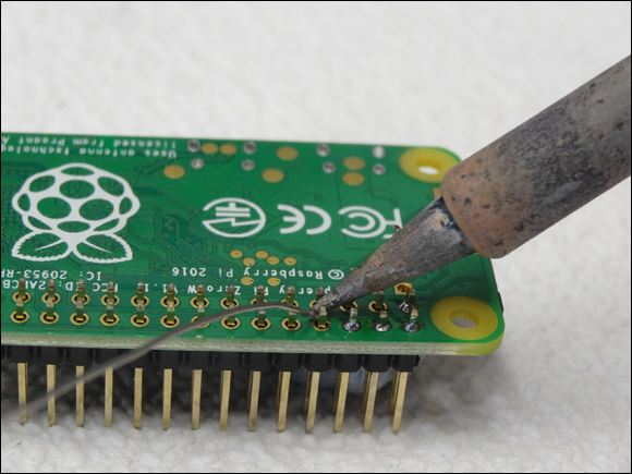
FIGURE 16-3: Soldering a header pin to a Pi Zero.
Getting at all the pins with one connector
Though a template is useful for identifying individual pins, you might want to transfer all the pins to a solderless breadboard, which consists of rows of sockets you can plug wires and other components into. This is a popular way of making a temporary circuit that is quick to change. One way of doing this is with a device called a cobbler, which consists of a ribbon cable and a printed circuit board. Figure 16-4 shows one of the various types you can buy — a T-Cobbler Plus, from Adafruit (www.adafruit.com). Many others are available, too.
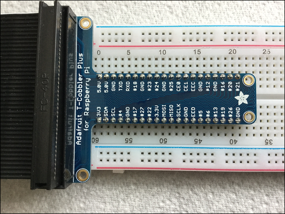
FIGURE 16-4: A typical cobbler connector, for bringing out all the pins to a breadboard.
One favorite of ours is the combined shield-and-bread-board from Dtronixs. (Check out www.dtronixs.com.) It has a small piece of breadboard that mounts directly over the Pi's GPIO pins and, as a bonus, has three LEDs and two push switches ready to be used, mounted on the side. This is shown in Figure 16-5.

FIGURE 16-5: The Dtronixs combined bread-board-and-shield.
Connecting things together
Once you know which pins are what, you have to connect them to other components to make a circuit. The best way to do this is to use jumper wires with pre-crimped connectors. Flexible wires often have their connectors crimped on, so the joint between them is made by squashing together the wire and connector. This method is more reliable than a soldered joint because no point of stress is created at the point in the wire where the solder ends. This is where the flexing wire breaks from metal fatigue. To be able to crimp successfully, the connector has a specially designed end to allow the wire and connector to join securely when squashed together with a special tool.
The proper name for the pin header on a Raspberry Pi is a Dupont connector; the part that slips on the pins is known as a female connector, and the part that plugs into a breadboard is a male connector. So, for connecting the header on the Pi into a breadboard, you need a female-to-male jumper wire. These often come as rainbow ribbon wires, which separate easily by simply pulling them apart. You can crimp the connectors yourself with the help of a crimping tool, but we recommend that you get them already crimped. For interconnections between points on a breadboard, you can use some male-to-male jumper wires, but most people use solid-strand wire with the insulation cut back a little. Do not put too fat a wire into a breadboard — you don’t want to stretch the connectors and make it too loose to fit components later. To this end, we recommend using wire with a 0.5mm diameter — otherwise known as 24 SWG (Standard Wire Gauge, used in the U.K.) or 24 AWG (American Wire Gauge, used in the U.S. and Canada ). It just so happens that, at this size, the two standards use the same numbers. Or, in the international IEC 60228 standard, which specifies a wire's cross-sectional area, it’s 1.5mm2.
Though electricity doesn't care about the color of the wire it’s flowing through, by convention red or orange is used for a positive wire, and black, green, or blue is used for a negative or ground wire.
Your First Circuit
The first thing anyone should do with a Pi system is to make an LED flash — because it’s the hardware equivalent of the “hello world” program. To light an LED, you need two components: the LED itself and a resistor to keep the current down to a safe level for the Pi's GPIO pins. The circuit diagram is shown in Figure 16-6, along with a diagram of the physical layout.
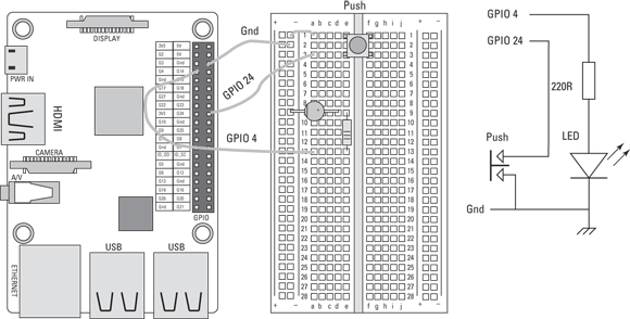
FIGURE 16-6: An LED and switch, wired to the GPIO pins.
Note: We have also added a push button input switch to this diagram, which we will use later for controlling the behavior of the LED.
Notice two points here: the orientation of the LED and the orientation of the switch.
LEDs are sensitive to the polarity of the current you put through them. The positive connects to the anode (the top flat bit of the triangle in the symbol), and the cathode (the bar in the symbol) goes to the negative. That way, the LED lights up; wire it the other way round, and it won’t. So, faced with an LED, how do you know which wire is which? Well, on a new LED, the anode normally has the longest lead, but what happens if the leads have been snipped? Well, examine closely the rim of the LED and you will see a portion of the round housing that is not curved but flat next to one lead. That lead is the cathode, or the negative end of the component. You can see the flat on the layout diagram.
With the push button input switch, you must get it the right way round, but for a different reason. Basically, there are only two contacts on a switch, and it doesn't matter which way the current flows through it. However, many popular, small push buttons, known as tack switches, (short for tactile) have four leads for mechanical stability, and each pair is connected together. In the layout and on the switch, you can see that the leads are on opposite sides of the rectangular base, with the other two sides not having a lead protracting from them. It’s the two leads on the protracting side that make contact when the button is pressed. So you need to orient the switch correctly — otherwise, it will act as if it were permanently pressed. If you ever get confused, resort to wiring the switch up to opposite corners, and that will ensure you wire it correctly.
As a general rule, you should never wire any circuit to the Pi when it’s powered-up. Also, you should never plug something into the Pi when it’s powered-up. This is because a circuit with incomplete wiring can present conditions that could damage the Pi or its components. Plugging something into an already-powered connector is known as hot-plugging, and special precautions must be taken to ensure the order in which connections are made. A device designed for hot-plugging, like a USB connector, will have the power and ground connectors longer than the signal connectors, to ensure these are connected first.
Bringing your LED to life
Once you have your circuit wired and connected, it’s time to bring it to life with software. Go ahead and boot up your Pi. (If you find that your Pi won't boot up, you have probably wired things up incorrectly, so immediately remove the power and check the circuit.) We show you how to use Scratch and Python 3 to make your LED blink.
Using Scratch 1.4
Scratch is a computer language we cover in more detail in Chapter 9, but the basic idea is that it uses graphic function blocks that the user drags and joins together to construct a program. It is very popular with children under 10 as it involves little in the way of typing. Scratch uses the broadcast block to communicate with the GPIO pins by using messages you type into the block. Open up Scratch, drag out the when green flag clicked block from the control panel. Then scroll down to the lower section of control blocks, and drag in a Broadcast. Click the down arrow in this block, and select New/Edit from the menu that appears. In the resulting input window, type gpioserveron and then click OK. This tells Scratch that you want to use the GPIO pins and to prepare itself to broadcast messages to it.
Now drag in another broadcast block from the control panel, and again select the New/Edit option from the drop-down menu and type in config4out. This makes Pin 4 into an output, so you can control the logic level on it. We want you to make this logic-level change between high and low. Because of the way the LED is wired, when the pin is high (in other words, the voltage on that pin is +3V3), the current will flow through the LED and resistor to make the LED light up. When the pin is low (the voltage is 0 volts), the LED is off. So drag out a forever loop block and drag a broadcast block into it. Into this broadcast block, type gpio4high. Then add a wait block after the broadcast block, and change the time from 1 to 0.3 seconds. Duplicate these two blocks, or drag some more in, and then change the broadcast message to read gpio4low. That’s all there is to it. The Scratch program should look like Figure 16-7. To try it out, click on the green flag and watch the LED blink.

FIGURE 16-7: Scratch program to blink the LED.
You can change the numbers in the wait blocks to change the blink speed. Note that the two wait block delays do not have to be the same; you can have a quick 0.3-second flash every second, if you want.
Control the flashing speed with an input
Using a GPIO pin as an input is simple: Just wire a push switch between the input GPIO pin and ground. Then when the switch is pushed, the pin is connected to ground, and when it is not, it isn’t connected to anything. As we demonstrate in Chapter 15, when a pin isn’t connected to anything and the computer reads it, then it can return any value because it picks up interference from the air. So, in order for it to work correctly — and to not give random values, you need to switch on the internal pull-up resistor. This connects the input to a logic high voltage through a resistor, so with nothing else electrically connected to the input, the pin will read as a Logic One. This will be the case when the button isn’t pushed. When the button is pushed, it connects the input to ground and so reads a Logic Zero.
Most of the time when you have an input, the code contains an if statement, because the main point of having a switch is to determine what section of code is to be run. Next, we show you how to write a program that selects one of two wait times, depending on the state of an input push button.
Start by getting a when green flag clicked block from the control panel, and then add a broadcast gpioserveon broadcast block, and a broadcast config4out block, as you did in the Scratch LED blink program. Then add another broadcast block, this time with a config24in message. This tells the GPIO to make the pin an input and enable the pull-up resistors. (You could also use the messages config24input, config24inpullup, or config24inputpullup — they all do the same thing, though some are more explicit that the pull-up resistors are enabled.)
Now add a forever loop and place an if … else control inside it. Then go to the Sensing controls list in Scratch and drag out a slider sensor value block. Use the drop-down menu arrow to make a gpio24 message. Go to the Operators control list in Scratch, and drag out a green comparison block — the one with two white squares and an equal sign (=) between them. Now drag the sensor value block into the white square on the left side and type 1 in the square on the right. Finally, drag these two combined blocks into the If Condition indent.
If you do not see the gpio24 option in the drop-down list, click on the round red stop button. This allows the option list to be refreshed, so try again.
Place a broadcast gpio4high block after the if block, and the wait 0.3 and wait 1 Second blocks in the if … else control. Finally, duplicate what is in the forever loop so far, and change the last broadcast block to gpio4low. After you have done this, you should see the program shown in Figure 16-8.
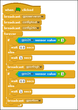
FIGURE 16-8: Scratch program to control the LED blink rate with a push button.
Click the green flag, and you should see the LED blink rapidly. When you press the button, the blinking slows down. Now, here’s a test: Change the bottom if so that it tests for being equal to 0, not 1. Before you try it, see if you can predict what will happen. Then make the change and see if you were right.
There’s a lot more to Scratch than LEDs and push buttons; it has built-in functions for driving things like servo motors, distance sensors, and even a camera. In addition, Scratch has functions for accessing the Internet to see weather reports. Some ready-built devices, like sensor shields, are also supported, or partially supported. For exploring other uses of GPIO pins that are built into Scratch, see the website at www.raspberrypi.org/documentation/usage/scratch/gpio/README.md.
The use of GPIO pins is controlled by different blocks in Scratch 2.0. The main incompatibility, however, is that it sets the GPIO pin's internal resistors to pull low by default. This means in place of connecting a push button switch between a GPIO pin and ground, it should be placed between GPIO pin and 3V3. Care must be taken not to connect it to 5V, or the Pi could be damaged.
Using Python
The Python language was introduced in Chapter 11 and, unlike Scratch's graphic-based program blocks, it uses entirely text-based instructions. Its great power is that the basic Python language can be extended to do more things by the use of libraries. These are functions that can be written in Python or any other language to extend what Python can do.
When using Python to access the GPIO pins, you have a number of different libraries you could choose that can give you access to them. They can provide not only normal input/output access but also access to some of the special functions or capabilities of certain pins. We have deliberately written the next two examples in in a style to match, as closely as possible, the two Scratch examples we have just presented, so that you can see how similar they are.
In the early days of the Raspberry Pi, the only access to the GPIO pins was if you were running in Supervisor, or Root, mode. Fortunately, this has now been changed so that you can run in normal User mode with most libraries.
While the newly introduced Thonny Python IDE (Integrated Development Environment) is popular with beginners, our preferred environment for writing Python is IDLE3 (it has more features), but either can be used. IDLE3 and Thonny can both be accessed from the main Desktop Raspberry menu. So, pick the one of your choice and create a new file, and then type in the program shown in Listing 16-1. Remember that, in Python, the case of a word matters as does the spaces at the start of a line, so be sure to get them right; otherwise, you will get errors when trying to run your code.
LISTING 16-1: LED Blink
#!/usr/bin/python3
import time
import RPi.GPIO as io # using RPi.GPIO

io.setmode(io.BCM)
io.setup(4,io.OUT) # make pin into an output

print("LED blinker - By Mike Cook")
print("Ctrl C to quit")
while True:
  io.output(4,0)
  time.sleep(0.30)
  io.output(4,1)
  time.sleep(0.30)
Save the file and run it. Your LED blinks just like the Scratch example.
Take a look at Listing 16-1 line by line. The program starts by importing the support packages you need. In this case, it’s the time package we use to achieve a Delay, or Wait, function, and the RPi.GPIO package to access the GPIO pins. Note here that a lot of examples use as GPIO in the import statement — but we prefer the simpler and shorter as io because it reduces the amount of typing and we don't have to keep switching to uppercase. Then you have to tell the library what sort of numbering system you want to use. We’re using the now-standard BCM system. The next line tells the GPIO pins that you want to use Pin 4 as an output. The setup method takes two values: the pin number and a number that tells the library to make that pin an output. This is conveniently hidden by the library, by using a predefined constant that’s defined in the library — that’s why it’s prefixed with io. Next, the loop forever of Scratch is carried out in Python with the use of the while True statement, with all statements in this loop indented.
This loop then commands the GPIO Pin 4 to be a 0, turning the LED off. Then there’s a delay (or sleep) for 300mS, followed by turning the LED on by making Pin 4 go high. Finally, there’s another delay, so you can see the LED in the On state. A common mistake is to leave out this last delay; as a result, the LED looks to be off all the time. So, controlling a GPIO output is very simple.
Now, on to the second example of a switch-controlled blink speed. This is shown in Listing 16-2, so open up a new file and type it in.
LISTING 16-2: An LED Blink Rate Controlled by a Push Button
#!/usr/bin/python3

io.setmode(io.BCM)
io.setup(4,io.OUT) # make pin into an output
io.setup(24,io.IN, pull_up_down=io.PUD_UP) # make pin an input

print("LED blinker - By Mike Cook")
print("Ctrl C to quit")
while True:
  io.output(4,0)
  if io.input(24) == 1:
     time.sleep(0.30)
  else :
     time.sleep(1.00)
  io.output(4,1)
  if io.input(24) == 1:
     time.sleep(0.30)
  else :
     time.sleep(1.00)
Listing 16-2 has the same commands for the output pin, but the input pin setup is new. This command has three parameters: the number of the pin to use, a number in the form of a constant defined by the library, specifying that this pin should function as an input, and, finally, some commands telling the computer to activate the internal pull-up resistor (although, to our ears, PUD_UP sounds more like a mother calling children to tell them their pudding is being served). The LED is first turned off as before, and then the input from the push button is read by the input(24) method, which returns a value of 0 or 1, depending on whether the pin is connected to the ground. This returned value is then compared to 1, and if it’s equal, a 300mS delay is made; otherwise, it produces a 1-second delay. The LED is turned on, and the Conditional Delay code is repeated.
Using GPIO ZERO
There’s a new kid on the block when it comes to accessing the GPIO pins in Python: the GPIO Zero library. Don't confuse this with the Pi Zero — the two are not related. The GPIO Zero library takes the class method approach to control, as opposed to the function method approach of RPi.GPIO and other, similar libraries. Pins become Python objects, which must be set up before use. Despite this complication, using this system is easy. For example, for our LED blink example, we can use the code in Listing 16-3.
LISTING 16-3: Python LED Blink
#!/usr/bin/python3
import time, os
import gpiozero as io # using LED zero

led = io.LED(4)  # make pin 4 into an output

print("LED blinker using gpiozero - By Mike Cook")
print("Ctrl C to quit")
while True:
  led.on()
  time.sleep(0.30)
  led.off()
  time.sleep(0.30)
Listing 16-3 at first looks very similar to the code in Listing 16-1 but only because we have written it to be like this. The library uses only the BCM method of pin numbering, so there’s no need to tell the library what system to use. An output pin is known as an LED, irrespective of whether that pin controls an LED, a motor, or a chip. So, the line that makes the pin an output is io.LED(4). This code segment returns a reference to the class object. Classes and objects are topics we cover in Chapter 17, where we describe how to write one, but basically, it’s a way to get the same piece of code to handle different specific objects — in this particular case, different GPIO pins. In order to know what it has to do, each thing/pin must be declared separately, and when it is, the program gets a code number to use to identify which specific thing it has to handle. That code number is placed into a variable called led in the Listing 16-3 example, but could be called anything. (This variable is known as the instance reference.) The class has methods associated with it — things it can do, in other words — and these are called up by writing the instance reference variable name, followed by a period or dot, followed by the method name. So, turning an LED on or off is a simple process — you just write led.on() or led.off(). However, in a way, this is a bit limiting. For example, you cannot send a number in a variable that’s used to turn the LED on or off — it has to be specifically spelt out as a method name. This is a limitation of how GPIO Zero is written, not a limitation of using classes. There are ways round this, but at this point, the simple system gets rather complex.
In fact, Listing 16-3 is written in a way that it looks a lot like the earlier listings. The same thing could simply be written as shown in Listing 16-4.
LISTING 16-4: A Simple LED Blink
import gpiozeroled = LED(4)
led.blink()
And that’s all you need. We aren’t sure what you can learn from this, apart from the wiring skills needed to attach the hardware, but it’s helpful for beginners. That last statement can have some parameters in it to control the blink rate — so, for example, to exactly match our other examples that last line could be:
led.blink(on_time = 0.3, off_time = 0.3)
This library has even more tricks up its sleeve. If you want to fade that LED up and down instead of just blinking, that last line could say
led.blink(on_time = 2.0, off_time = 2.0, fade_in_time = 1.0, fade_out_time = 1.0 )
This is great if you only want to do that, and for a very young beginner, that’s exactly what you want to do.
The blinking speed controlled by a push button can be written as shown in Listing 16-5.
LISTING 16-5: A GPIO zero example of an LED Blink Controlled by Push Button
#!/usr/bin/python3
import time, os
import gpiozero as io # using GPIO Zero

led = io.LED(4)          # make pin 4 into an output
push = io.Button(24)        # make pin 24 into an input

print("LED blinker switch using gpiozero - By Mike Cook")
print("Ctrl C to quit")
while True:
  led.on()
  if push.is_pressed:
     time.sleep(0.30)
  else :
     time.sleep(1.00)
  led.off()
  if push.is_pressed:
     time.sleep(0.30)
  else :
     time.sleep(1.00)
The input works in a similar way to the output. In this case, you make an instance of the Button class and put its reference in the variable push. Then you use the is_pressed method of this class to determine the time delay in the blinking. By default, the input pull-up resistor is enabled when you create the class reference.
There are other options contained in this input class. It can specify whether a press is to be auto-repeated or specify a debounce time — the time after a change to ignore further changes. (We take another look at debouncing later in this chapter.) As well as the is.pressed method, other class methods include is_held, wait_for_press, wait_for_release, is_held, when_held, when_pressed, and when_released. Rather than return any information about the input, these last two cause a function to run when the button is pressed or released. This other function runs in a separate thread — in effect, another separate program — with this thread and the main code being swapped in and out alternately until the function is complete. This gives a beginner access to complex concepts that they need to understand only when something goes wrong. So, our controlled blink-rate program could be written as shown in Listing 16.6.
LISTING 16-6: GPIO Zero-Specific LED Blink Controlled by Push Button
#!/usr/bin/python3
import gpiozero as io # using LED zero
from signal import pause
led = io.LED(4)          # make pin 4 into an output
push = io.Button(24)     # make pin 24 into an input

def blinkFast():
    led.blink(on_time = 0.3, off_time = 0.3)

def blinkSlow():
    led.blink(on_time = 1.0, off_time = 1.0)

push.when_pressed = blinkFast
push.when_released = blinkSlow

pause()
The pause function, in effect, ends the program, and the only thing that happens is when the callback functions, as they are called, are invoked or triggered on the push or release of the button.
A lot of the programming work involved in using GIPO Zero involves leafing through the documentation to see what simple functions the authors have implemented for you. GPIO Zero enables you to get results quickly, and without needing to understand much of what is going on — which is helpful if a function does what you need. However, we can't help but feel that although some things can be done simply, the skills learned are not exactly transferable. As you develop more complex electronic projects, you might find GPIO Zero to be too limited for your needs.
Starting Out with a Dice Display
After you have the basic toolkit of dealing with the GPIO pins under your belt, it’s time for a bit of fun with some projects. First off, let's look at making a computer-controlled dice.
A dice display
Now, before you get pedantic about our closing statement in the previous section and state that there’s only one dice, so it should be called a die, let us point out that in modern standard English, dice is both the singular and the plural. To throw the dice could mean one, or more than one, dice. An online search will verify this definition.
A dice display is a good project to start with because it not only makes a useful and interesting replacement when you want to use one in playing a game but also serves to introduce some important programming concepts. Basically, it’s simply seven LEDs and a push button, so it isn’t much different from the circuit we describe earlier in this chapter. However, the arrangements of the LEDs is vital to the final effect, and it’s important to get the correct LEDs in the correct spatial position. Figure 16-9 shows the basic schematic.

FIGURE 16-9: LED dice schematic.
The actual GPIO pins you use for the LEDs doesn’t matter because the relationship between the LEDs and the pins is defined in software — if you get it wrong, you can correct it in the pattern lookup table. However, for a trouble-free experience, follow our GPIO usage. Note that the schematic is quite clean and straightforward. It follows the rules of positive signals at the top and ground signals at the bottom, with a minimum number of wires (in this case, none) crossing. Also, the signal flow is from left to right. This is a good example of a schematic. When it comes to the physical layout, Figure 16-10 shows one way of wiring this up on a breadboard.
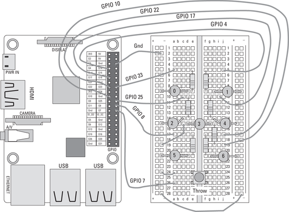
FIGURE 16-10: LED dice physical layout.
You will instantly see that this layout is altogether more cluttered, which makes it difficult to see what is happening, although it does show you where to place all the parts and wires. Note that LED 2 and LED 4 have their legs bent slightly to allow them to physically line up with LED 3 and get a good match to the die pattern. Though it’s easy to go from the schematic to the layout in your head, it’s almost impossible to go in the other direction if the circuit is anything other than trivial. We did cheat a bit here and pick the GPIO pins so that we could draw the physical layout without having any wires cross, which would have made it even more cluttered. You can't always do that.
We strongly recommend that you don't rely on physical layout diagrams, but instead learn the simple process of converting the schematic into a layout. There’s no need to plan it all out beforehand — just take it one wire at a time and build it up. It’s a skill that’s easy to learn and that will pay you back handsomely as you progress through your learning of this subject.
Figure 16-11 shows a photograph of the hardware for our project. We ended up using 3mm diameter LEDs for it. Note how it’s even more messy than the layout diagram. There are two causes for such messiness: First of all, you can't easily bend the wires out of the way so that they don't obscure anything. Second, the whole point of using breadboard is so that you can reuse its components. This means you generally don't snip the component leads to be short and close to the board — you leave them sticking out high above the board.
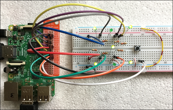
FIGURE 16-11: Photo of the LED dice project.
The project
When doing any project, no matter how small, it always pays to take it one step at a time and test as you go. So, the first thing to do is to test your hardware before you get into anything fancy. You can simply extend the LED blink program to blink all the LEDs or, if you aren’t up to that, simply take the LED blink program and change the GPIO number to one number you’re using here. Run that and see the correct LED flashes, and then stop the program and change to another number. Repeat until all the LEDs (as well as the push button) have been tested.
The project splits up into two main parts: Generate the random number between 1 and 6 and then display it.
The numbers
There are two ways to generate the random numbers: Use the computer's random-number generator or use some random event. The problem with the random-number generator is that it’s not really a random-number generator. It’s a pseudo random-number generator — the sequence of numbers is fixed and will repeat every time you run the program, unless you seed it by picking a random starting point in this sequence. Because the sequence is very long, this approach will appear to be a random number. (The Python random-number generator uses as the seed the length of time the system has been powered on.)
However, a better way is to use something that is by its nature truly random: In this case, we use the length of time the user has pressed the button, indicating a new throw. You might not think this is random, because the user could just make a long press or a short press and that would influence the number that’s produced. However, this doesn’t take into account that the timing of a press can be very accurate and that all six numbers are cycled through many thousands of times a second. Controlling a button press with microsecond accuracy is simply not possible for us slow humans, so it’s a good source of random numbers. Therefore, in our project, the number is generated by counting from 1 to 6 while a push button is held down.
When a push button is first pushed, the contacts come together and then bounce apart and then come together in a rapid sequence of contact make-and-break, rather like a ping-pong ball falling onto a table. This happens on all mechanical switches, but some designs are worse than others. A lot of the time in programming, this isn’t important because other stuff happens after a contact is first made. Other times, it could be a problem, but the solution can be quite simple — just delay for a few milliseconds after the first contact before looking at the input again. This strategy — known as debouncing an input — is what we show you how to do in this project.
The display
Once you have generated a number, it must be displayed in the pattern of a conventional dice. This involves turning on a specially selected pattern of LEDs. This pattern is, of course, different for each number. Now, you could use a series of if statements to test for each possible number, and when you find a match, write a series of statements to turn on and off the appropriate LEDs. An example of this for one number using the GPIO Zero library would look like the code in Listing 16-7.
LISTING 16-7: Fragment of Code to Set a Pattern
# the variable dice_number contains the number to display
if dice_number == 3: # make the three pattern
   led0.off()
   led1.on()
   led2.off()
   led3.on()
   led4.off()
   led5.on()
   led6.off()
 if dice_number == 4:  #if the number is four then
   led0.on()
   ……… and so on
You can see that this listing is easy to read, but it contains the most awful, turgid, repetitive code and is much longer than necessary. (This is typical of what a beginner might produce.)
Turgidness in not confined to the GPIO Zero library — you can write bad code like this with any library.
You might wonder why it matters, as long as the code works. Well, if you can understand the concepts of doing it properly, you can apply them in situations where code like this will not work or is far too long. Even so, before you can begin to write any code, you need to know what LEDs to turn on and off to display each number. Figure 16-12 shows the patterns we have decided to use to represent the dice pattern. Note that the main choice is which diagonal to use for representing 3 and 2. We think it’s best using the opposite diagonal for the two numbers, but we have no preference for which diagonal to use.

FIGURE 16-12: LED dice display patterns.
Given the physical arrangement of LEDs shown, each number needs to be displayed by having certain LEDs on and off. This pattern can be summarised as a sequence of 0s and 1s and is shown in the Binary Pattern column in Figure 16-12. Binary is a way of writing numbers that exactly matches how those numbers are stored in the computer as a sequence of 1s and 0s. A single digit is called a bit. Everywhere the LED is on, there’s a 1 in the binary pattern, and there’s a 0 when it’s off. This pattern can define the LED pattern, functioning as a concise store of the pattern you need. In a program, it’s way easier to express this pattern as a hexadecimal number, because with a little practice, you can convert from a pattern to a number in your head — and it’s then easy to read the code. Hexadecimal is a number system that groups a byte, or 8 bits, into two 4-bit groups. Each of the two groups is then expressed as a single character — from 0 to 9 and then the letters A to F. This gives 16 different characters that represent the 16 different patterns of 1s and 0s you can get with four bits. This is shown in the Hex Pattern column of Figure 16-12, as far as the computer is concerned, if you start a number with 0x, it treats what follows as a hexadecimal number.
In Figure 16-12, we show — for the sake of completeness — the equivalent number in decimal notation, which is the counting system we humans use. No one in their right mind would dream of using it in a program — although it would work because it follows the correct pattern, it’s almost impossible to know what the pattern is by just looking at the number. In other words, it makes for bad code.
Keep in mind that the actual numeric value of this pattern number has no meaning at all — the meaning is in the binary bit pattern. Often, beginners ask how to convert a number into binary, but there’s no need because any number stored in the computer is already in binary format. Only when you need to do a task like printing it out do you need to convert a number from binary into something else, and the print statement does that for you. All you need now is some way to read that “bit pattern number” and turn it into the action of switching the LEDs on and off. In effect, you have to unpack that information and turn it into a pattern — and do it efficiently without turgid code.
So let's break this down and see if you can do this for only one bit of the pattern — let’s say the least significant, or right-hand, bit. If it is 1, turn on the LED, and if it’s 0, turn it off. You can handle that task with this line:
io.output(LEDnumber,pattern & 1)
The variable LEDnumber has, as you might suspect, the LED number you want to control, and the variable called pattern has the bit pattern you’re trying to produce. The & symbol means the arithmetic AND operation. The AND operator takes two numbers and considers the contents of each bit position individually. If both numbers contain a 1 in the same position, the result is a 1. Otherwise, the result for that position is 0. So, when you’re ANDing the number 1 with the pattern number, the result is to zero, or remove, all bits except the least significant one, which is left alone. In other words, it isolates a single bit in the pattern variable. So if the least significant bit in the pattern variable was a 0, that operation returns a 0. If it was a 1, that statement returns a 1 — which is just the number you need to put in the output command to turn that LED on or off. (We say that the number 1 here is a mask because it masks out bits you don't want.)
Now, what about the LEDnumber that changes every time we want to look at a different bit in the pattern? Instead of a single number here, we actually need a list. The list is made up of the GPIO numbers that control each LED. So the first element in the list is the GPIO number that controls LED 0, which, according to the schematic, is GPIO 23. Finally, you need a way to move the bit pattern in the pattern variable one place to the right so that the same instruction will do the same thing for the next bit. You can do this with a shift-to-the-right operator (>>), so you can have a little loop that generates the pattern:
LEDnumber = [23,4,25,10,17,8,22]
for i in range(0,len(LEDnumber));
  io.output(LEDnumber[i],pattern & 1)
  pattern = pattern >> 1
And that’s all there is to it — no turgid code at all. It’s short, concise, and easy to write.
Finally, we have added the small, fun feature of a dice roll display. This shows several random dice patterns in quick succession, to give the impression that the dice is being rolled.
We’re all ready to show you how to write the full code. This is shown in Listing 16-8.
LISTING 16-8: LED Dice
#!/usr/bin/python3
# Electronic dice.  By Mike Cook
import time, random
import RPi.GPIO as io

LEDnumber = [23,4,25,10,17,8,22]
dicePattern = [0,0x08,0x41,0x2A,0x63,0x6B,0x77]
pushButton = 7

def main():
   print("Electronic Dice Ctrl C to quit")
   initGPIO()
   number = 1
   while 1:
      displayRoll()
      displayNumber(number)
      number = generateNumber()

def displayRoll(): # pattern to show when rolling
   for i in range(0,20):
     displayNumber(random.randint(1,6))
     time.sleep(0.1)

def displayNumber(number):
    pattern = dicePattern[number]
    for i in range(0,len(LEDnumber)):
       io.output(LEDnumber[i],pattern & 1)
       pattern = pattern >> 1

def generateNumber(): # wait for a push
    throw = random.randint(1,6)
    while io.input(pushButton) == 1:
        pass
    time.sleep(0.030) # debounce delay
    while io.input(pushButton) == 0:
       throw += 1
       if throw >6: # wrap round the number
          throw = 1
    return throw

def initGPIO():
   io.setmode(io.BCM)
   io.setwarnings(False)
   for pin in range (0,len(LEDnumber)):
      io.setup(LEDnumber[pin],io.OUT) # make pin into an output
   io.setup(pushButton,io.IN,pull_up_down=io.PUD_UP) # make pin ↩into an input

# Main program logic:
if __name__ == '__main__':
    main()
When this code runs, it loads in the libraries, sets the global variables, defines all the functions, and then, finally, starts running the main function. This is where the action is coordinated, and it’s a good idea to make it as short as you can. The main function prints out a message, initializes the GPIO pins and number to display, and then starts an infinite loop, displaying the roll pattern and the dice number and then generating the next number when the button is pressed again.
Beginners often try to cram everything into the main function, but using some well-named functions makes it much easier to see what’s going on. These functions could, of course, be called anything, but for readability, make them as descriptive as you can. This benefits not only others reading your code but also, more importantly, you in six months’ time, when you have forgotten what is going on.
One thing that might puzzle you is that the dice pattern list starts off with a 0. This was not shown in Figure 16-12, so why is it there? Well, all lists are numbered starting at 0, and the first pattern you’re interested in is the pattern for a throw of 1. So, in order to align the position of the pattern information with the position in the list, you must start out with a blank entry — so that, for example, the information for the number 4 is in the fourth position on the list. The rest of the code ensures that 0 will never be required to be displayed.
Looking more closely at Listing 16-8, the displayRoll function is simply a loop that calls the displayNumber function 20 times, giving it a random number between 1 and 6. It shows each number for one-tenth of a second. The displayNumber function should be familiar to you from earlier mentions in this chapter. The one function that may need close examination is generateNumber. It starts out generating a random number called throw, and then it waits in a while loop until the push button is pressed. When this is detected, a 30ms delay ensures that any contact bounce is finished before another while loop looks to see if the button has been released. Though the program is in this loop, it increments the throw variable, and when the maximum value of 6 is exceeded, the throw variable is reset to one. The last line returns this throw value to the calling line. The line in the main function
number = generateNumber()
ensures that this return value is placed in the variable called number.
Taking it further
We encourage you to play around with all the code you find in this book, by making your own changes and extensions. One area that’s fun to play with is the roll animation. Instead of showing random numbers, you can make any sort of display you like in the same way as you defined the patterns for the dice display. As a start, we have written an alternate function for the display roll, as shown in Listing 16-9. You should use this code to replace the function of the same name in Listing 16-8. You should save any changes you make using a different filename if you want to keep them.
LISTING 16-9: An Alternate displayRoll Function
def displayRoll(): # pattern to show when rolling
   rollPattern = [0x01,0x03,0x07,0x0F,0x1F,0x3F,0x7F,0,0]
   for roll in range(0,len(rollPattern)):
      pattern = rollPattern[roll]
      for i in range(0,len(LEDnumber)):
         io.output(LEDnumber[i],pattern & 1)
         pattern = pattern >> 1
      time.sleep(0.2)
This has a new list of patterns to be used in the roll — called, appropriately enough, rollPattern. You can write your own numbers in here and use as many of them as you want. The code ensures that all pattern numbers you write in here are displayed. Can you change the numbers in the rollPattern list so that a single lit LED goes round the dice display? You could also change the speed of the dice roll display, making it longer between display changes as it comes to an end. If you want to use binary numbers to define the pattern, you can use
rollPattern = [0b1,0b11,0b111,0b1111,0b11111,0b111111,0b1111111,0,0]
Note that there’s no need to specify leading 0s, but, personally, we find binary much harder to read in a line of code than hex because it’s easy to lose your place amongst all those 1s. If you like this project, we encourage you to put all the electronics in a box and connect it up to the Pi with a multiway header and ribbon cable.
Pedestrian Crossing
The dice project covered in the preceding section is all about displaying patterns. The Pedestrian Crossing project is about time and sequences. It simulates a U.K. pedestrian crossing — basically, a traffic-light–controlled crossing initiated by the pedestrian’s pressing a button. These crossings are also common in the United States, but a little of the detail may be different from state to state, so let’s first go through the sequence we’re trying to simulate.
The crossing has a three-light traffic control — red, amber, and green — and the pedestrian has a two-light system — Cross (or Walk ), which is green, and Don't Cross (or Don't Walk), which is red. The normal state of the crossing is that the green light is on for the traffic and all the other lights are off. There’s a button at the crossing for the pedestrian to request a stop, and a traffic sensor is buried in the road. This sensor controls how quickly the crossing sequence will start after the pedestrian presses the button. If no traffic has been detected recently, the crossing sequence starts immediately; otherwise, there’s a delay. This ensures that a busy road isn’t stopped too many times by pedestrians or jokers, whereas a quiet road will not make pedestrians wait long before they can cross. Once the Cross Request button is pressed, the Don't Cross light immediately comes on.
When the crossing sequence begins, the green traffic light turns to amber and then to red. Then the green crossing light comes on and, at many crossings, a sounder “bleeps” to help blind people cross. After a period of time, it may be safe to continue crossing but not be safe to start a crossing, so the green cross light and the amber traffic light flashes, and the sounder no longer bleeps. Then the Don't Cross light comes on, with the traffic light remaining amber, and, finally, the traffic light goes to green and all pedestrian lights go out.
This sounds straightforward on the face of it, but the traffic sensor needs to be monitored through this sequence, to ensure that you don't miss any traffic that may drive up and stop during the crossing sequence and allow the next crossing to occur too quickly. This means you can't just use a simple time.sleep delay to control the sequence; you need what is known as a state machine — this is a way of juggling two or more processes while making it look like they’re happening at the same time.
A state machine is an important technique — and one that you’ll need over and over as you take on more projects.
The idea of a state machine is that most things do not need the processor's full attention. The LED blink program, for example, spends virtually all of the time in the sleep function, just waiting for time to pass. Instead of burning that time, the idea of a state machine is to spend it looking after other tasks. In order to do this, you have to have some idea of when your tasks need attention, so you incorporate a variable that specifies the time each task needs to be looked at next. This is made possible by the time.time() method of the time library, which returns a floating-point number (one with decimal places) of the time (in seconds) that the Pi has been switched on. The thing is that you don't actually care what this number is, because you use it as a relative measure to find out when to do the task.
Let's look at a simple example first — blinking two LEDs independently.
First of all, go ahead and wire up two LEDs and resistors, connecting them to GPIO 23 and 24, as shown in Figure 16-13.

FIGURE 16-13: LED wiring for independent blinking.
Now we’ll describe how to blink these two LEDs at totally independent rates. The state of each task is given by a state variable, with the two values 0 or 1. The state variable shows if the light is on or off so that you know what you need to do for the next stage of the blinking task. The time between each change of state of the LEDs is controlled by a variable that gives the time the change must occur. This time is calculated by adding the current time to the length of time you want to elapse before the next LED state change. This can be the same for all states or different for each state. The example in Listing 16-10 has the same time for the on/off times of LED1, but a separate on/off time for LED2.
LISTING 16-10: Blinking Two LEDs at Different Rates
#!/usr/bin/python3
# Two blinks  By Mike Cook
import time
import RPi.GPIO as io

led1pin = 23
led2pin = 24
led1BlinkRate = 0.5 # the speed of blinking
led2onTime = 0.5 ; led2offTime = 0.51
led1State = 0
led2State = 0
blink1Time = time.time()
blink2Time = time.time()

def main():
   print("Two blinks Ctrl C to quit")
   initGPIO()
   while 1:
      if time.time() > blink1Time:
          blink1()
      if time.time() > blink2Time:
          blink2()

def blink1():
   global blink1Time, led1State
   if led1State == 0:
      io.output(led1pin,1)
      led1State = 1
   else:
      io.output(led1pin,0)
      led1State = 0
   blink1Time = time.time() + led1BlinkRate

def blink2():
   global blink2Time, led2State
   if led2State == 0:
      io.output(led2pin,1)
      led2State = 1
      blink2Time = time.time() + led2onTime
   else:
      io.output(led2pin,0)
      led2State = 0
      blink2Time = time.time() + led2offTime

def initGPIO():
   io.setmode(io.BCM)
   io.setwarnings(False)
   io.setup(led1pin,io.OUT) # make pins into outputs
   io.setup(led2pin,io.OUT)

# Main program logic:
if __name__ == '__main__':
    main()
The program spends most of its time in the while loop in the main function, checking to see if it’s time to call any of the two functions blink1 and blink2. (Note: You can, of course, have as many functions here as you want.) When the functions are run, they do what they need to do given that task's current state, which, in our simple case, involves turning the LED on or off. Then you advance the state counter and, finally, set the time when this function/task needs to be done again. If the task is being advanced at a constant rate (like the blinking LED1), then this is done at the end of the function. If each state needs to last a specific length of time, that is set when the state count is advanced.
When you run the program, you see both LEDs blinking in unison; but, as time goes by, the two become increasingly out of sync until they are seen to be blinking alternately, and, in another minute, they will drift back in sync. This is because the full cycle of LED2 is 0.01 seconds longer than LED1.
Play with these times to see how it changes things. Can you change the code to add two more LEDs into the mix?
The Pedestrian Crossing hardware
After you have all the background information you need to make the Pedestrian Crossing project, let’s start, as always, with the hardware. Figure 16-14 shows how it should be wired up.

FIGURE 16-14: Pedestrian Crossing schematic.
The diagram is quite similar to what we have shown you in this chapter, except that it’s arranged differently. First, there are two push buttons for the traffic sensor and cross request. Next are five LEDs connected to resistors and GPIO pins. Note here, though, that you need different colours of LED — two red, two green, and a yellow. Finally, there’s the sounder. We’re using a piezo electric sounder, but a word of warning is in order here: There are two types of piezo electric sounders, and there seems to be no universally accepted word to differentiate between the two. The sort you want is one that generates sound when you apply a voltage to it. These could be called self-drive sounders, but sometimes they are not. Other times, they can be referred to as buzzers, but don't confuse them with electromechanical buzzers, which take a lot of current — too much current for the Pi. A suitable one would work from 3V and take less than 10mA. The type you don't want is the one where you have to supply an electrical pulse train to it before it makes a noise. This type is sometimes called a speaker-type sounder. A simple test is to wire the sounder to the 3V3 output and ground of the Pi and then make and break the contact. If it only clicks, it’s a speaker type. If it makes a sound, it’s the type you want to use. (To be honest, in development, we replaced the sounder with an LED and a resistor, to reduce the annoying bleeps.)
The layout of this circuit on a breadboard is shown in Figure 16-15. We have arranged the traffic-control LEDs like traffic lights, and the cross indicators above each other like you would find on a real-life crossing.

FIGURE 16-15: Layout of the Traffic Crossing circuit.
The Pedestrian Crossing software
Now let's apply the multi task/state machine principle to our crossing project. We need one task to look at the traffic sensor — if we see traffic activity, we want to note the time it took place. Then we need one task to look at the cross request button — if that button is pressed and the crossing sequence isn’t under way, we need to start that sequence. Finally, if the crossing sequence has reached the “cross phase,” we need a task to turn the sounder on and off, to make the bleeping noise. (Note that we have reduced the times in the crossing sequence to be easy to look at and see what is going on. In real life, some of the times would be much longer.) The software for this project is shown in Listing 16-11.
LISTING 16-11: Pedestrian Crossing Project
#!/usr/bin/python3
#!/usr/bin/python3
# Pedestrian crossing  By Mike Cook
import time, random
import RPi.GPIO as io

LEDcontrol = [23,24,25,4,17,9]
# GPIO for Traffic Red, amber, Green & noCross cross sounder
crossRequest = 7
trafficSensor = 18
nextSequenceTime = time.time()

def main():
   global lastTraffic, state, bleep
   print("Pedestrian crossing simulator Ctrl C to quit")
   initGPIO()
   io.output(green,1) # Green light on to start
   state = 0
   bleepTime = time.time()
   bleep = False
   lastTraffic = time.time()
   while 1:
      checkTraffic()
      if checkRequest() and state == 0 :
         io.output(noCross,1) # turn on the no cross light
         if time.time() - lastTraffic > 10.0: #cross immediately
             state = 1
         else:
             time.sleep(10.0) # let traffic flow for a bit
             state = 1
      crossSequenceFunction()
      if bleep and time.time() > bleepTime:
         bleepTime = time.time() +0.3
         io.output(sounder,not(io.input(sounder)))

def checkTraffic():
   global lastTraffic
   if io.input(trafficSensor) == 0:
      lastTraffic = time.time()

def checkRequest():
   request = False
   if io.input(crossRequest) == 0:
      request = True
   return request

def crossSequenceFunction():
   global nextSequenceTime,countFlash,state,bleep
   if state == 0:
      nextSequenceTime = time.time() + 2.0
      return
   if time.time() > nextSequenceTime :
       if state == 1: # show amber
          #print("doing state",state)
          io.output(green,0)
          io.output(amber,1)
          state = 2
          nextSequenceTime = time.time() + 2.0 #show amber time
       elif state == 2: # show red
          #print("doing state",state)
          io.output(amber,0)
          io.output(red,1)
          state = 3
          nextSequenceTime = time.time() + 2.0 # show red time
       elif state == 3: # show cross light
          #print("doing state",state)
          io.output(noCross,0)
          io.output(cross,1)
          bleep = True
          state = 4
          nextSequenceTime = time.time() + 5.0 #crossing time
       elif state == 4: # change to amber clear crossing
          #print("doing state",state)
          io.output(amber,1)
          io.output(red,0)
          bleep = False
          io.output(sounder,0) # turn off sounder
          state = 5
          nextSequenceTime = time.time() + 1.0
       elif state == 5: # flash amber and cross
          #print("doing state",state)
          io.output(amber,not(io.input(amber)))
          io.output(cross,not(io.input(cross)))
          nextSequenceTime = time.time() + 0.2 #flashing speed
          countFlash +=1
          if countFlash > 20 : #clear crossing time 20 * flash speed
             countFlash = 0
             state = 6
       elif state == 6: # hold amber
          io.output(cross,0)
          io.output(noCross,1)
          io.output(amber,1)
          state = 7
          nextSequenceTime = time.time() + 2.0 # hold amber time
       elif state == 7: # put on red light
          #print("doing state",state)
          io.output(amber,0)
          io.output(green,1)
          io.output(noCross,0)
          state = 0
          nextSequenceTime = time.time() + 1.0


def initGPIO():
   global red, amber, green, noCross, cross, countFlash, sounder
   io.setmode(io.BCM)
   io.setwarnings(False)
   for pin in range (0,len(LEDcontrol)):
      io.setup(LEDcontrol[pin],io.OUT) # make pin into an output
      io.output(LEDcontrol[pin],0) # set to zero
   io.setup(crossRequest,io.IN,pull_up_down=io.PUD_UP) # make pin into an input
   io.setup(trafficSensor,io.IN,pull_up_down=io.PUD_UP)
   red = LEDcontrol[0]
   amber = LEDcontrol[1]
   green = LEDcontrol[2]
   noCross = LEDcontrol[3]
   cross = LEDcontrol[4]
   sounder = LEDcontrol[5]
   countFlash = 0

# Main program logic:
if __name__ == '__main__':
    main()
Stepping through this program , first note that the GPIO pins are initialized and that each pin in the list is given its own name. This makes the program easy to read, although we could have used a “magic number” — a number that appears for no immediately apparent reason — as an index in the GPIO list. In the infinite while loop in the main function, traffic activity is first measured and then the Cross Request button is looked at. The function checkRequest returns a value of True if the button is being pressed. That means the function can be called directly inside an if statement — there’s no need for any intermediate variables. Also, the if statement looks to see if a cross sequence is in operation by looking at the state variable. (It’s 0 if nothing is running.) If a cross request has been made, a delay occurs if there has been some traffic activity in the last ten seconds, and then the state variable is changed to a value of 1.
Next in the main loop, the crossSequenceFunction is called, which only returns if the state variable is 0; otherwise, the function looks to see if it’s time to change the state, and returns if it isn’t. Finally, in the main loop, the bleep variable is looked at because it controls when the sounder should make a noise. This variable is set at State 3 of the crossSequenceFunction and cleared at State 4. The crossSequenceFunction, for most steps, simply turns on or off the various lights according to the required sequence. The exception to this is in State 5, where both the cross light and the amber light need to flash. We do this by toggling the two lights. (Toggling means turning off a light that is on, and turning on a light that is off.) Rather than use a variable to tell you if you set the light on or off last, you can use a little trick: Read the state of a GPIO output pin. This then gives you the value you last set it to, and you know you want to use the inverse of this state. Therefore, the line
io.output(amber,not(io.input(amber)))
sets the amber light to the opposite state to its current state. Before you can get out of State 5 and advance it to State 6, you must have ten flashes of the lights. Finally, in State 7, you set the traffic lights to green for go and return the state machine variable back to State 0, which indicates that the cross sequence is no longer in progress.
Taking it further
There are a number of print statements we have commented out, to show the state of the Cross sequence; you might like to uncomment them to see what is going on, although the LEDs should tell you. You can go and measure the times on an actual crossing and replace the times used in the program with realistic times. You can extend the program so that there’s a more intelligent traffic-control system, by counting the cars over a set interval — say, the last 20 seconds — and graduating the Wait Before Crossing sequence delay is lengthened accordingly.