
Chapter 17
Lots of Multicolored LEDs
IN THIS CHAPTER
![]() Finding out how to use an RGB LED
Finding out how to use an RGB LED
![]() Discovering the APA102C integrated LED and driver
Discovering the APA102C integrated LED and driver
![]() Writing a class driver for the APA102C
Writing a class driver for the APA102C
![]() Making a Rainbow Invaders game
Making a Rainbow Invaders game
![]() Designing a Keepy Uppy football game
Designing a Keepy Uppy football game
![]() Discovering more LED strip shapes
Discovering more LED strip shapes
![]() Creating a wearable colorful broach
Creating a wearable colorful broach
Chapter 16 shows you how to control LEDs in terms of both patterns and sequences. Now we’re going to get colorful and look at multicolored LEDs. We use different colors of LED in Chapter 16’s Pedestrian Crossing project, where each LED has its own color. Another type of LED contains three different colored LEDs in the same package. This type is known as an RGB LED because the three colors are red, green, and blue.
RGB LEDs come in three basic forms: common anode, common cathode, and separate connections. This last type, the least common, only comes in a small, 6-pin, surface-mount package. (This type is used in the Pimoroni Sense HAT, mentioned in Chapter 15.) The internal configuration of the three types is shown in Figure 17-1.

FIGURE 17-1: Three types of basic RGB LEDs.
The dotted box around each LED is the way a schematic shows that they’re all in one package. Note that the common anode and common cathode types have four wires going into them instead of the normal two wires for a single-color LED. Each LED can be treated by the software as a separate LED. To use common anode LEDs, you have to wire them up so that the GPIO pins act as current sinks, that is making the connection to ground. The wiring for the two common “something” LED types is shown in Figure 17-2.

FIGURE 17-2: Wiring common anode and common cathode LEDs.
With a common cathode, the GPIO pins should be set to a logic high to turn the LED on, and to a 0 to turn it off. (For more on logic highs and zeros, see Chapter 16.) However, with a common anode LED, this situation is reversed, with a logic low turning on the LED by sinking current and making a complete circuit that way. When confronted by Figure 17-2, a beginner typically has this question: “Why do I need to have three resistors? Why can’t I just have one in the common line?” — to which the answer is, “Yes, you need all three resistors.”
Here’s why. If you only have one resistor, then the voltage level that the resistor will drop depends on the current running through it. That means the brightness will change depending on which LEDs are turned on. Even worse, if the red LED is on, there’s not enough voltage across the other two LEDs to turn them on. This is because each color of LED drops a different voltage when it is on, and red drops the lowest voltage. It will appear that the other colors are not working — not good.
Making Colors
With the wiring schematics out of the way, it’s time to turn to the fun stuff: mixing colors. Yes, you can turn on just one LED at a time, and that will give you one of the three colors — red, blue, or green. However, turn two on and the colors will mix in a way known as additive mixing. The primary colors are red, green, and blue. Mixing them together gives you other colors, the so-called secondary colors. So a red-and-green light together make a yellow one. A green-and-blue light make a cyan color, and a red-and-blue light make magenta. Turn on all three LEDs together and you make white — or, more precisely, they make a white tint.
 In theory, all three LEDs on together will make white, but in practice this depends on the exact brightness of the three separate lights. They have to be identical to make a pure white; otherwise, the white looks tinted, which is not altogether a bad thing. It's not an easy task to do this, because each color has a different forward voltage drop — you need different resistors to ensure the same current through each LED. Not only that, each color of LED converts current to brightness with a different efficiency, which complicates things tremendously.
You might be used to mixing colored paint, but keep in mind you get different results doing this than mixing light. Paint mixing is known as subtractive mixing because each paint color you put into the mix takes out (or subtracts) some other color. This is how your color printer works. For subtractive mixing, the primary colors are cyan, magenta, and yellow; red, green, and blue being the secondary colors.
Using diffusers
The light from three LEDs in the same package will still be seen as three separate points of light, unless there is some sort of diffuser, which allows the light to mix evenly. For individual RGB LEDs, this is sometimes provided by the package or body of the LED itself. Viewing distance alone can provide enough diffusion to mix the colors, but often a diffuser of some sort will help. Diffusers also reduce the brightness per unit area of the LED, making it much easer to take a good color picture.
You can use anything that is translucent as a diffuser. Our favorite is a very thin styrene sheet — about 0.5mm thickness is fine and is easy to work with, because it can be cut with scissors. (A good alternative is a simple sheet of paper.) If you have several LEDs and want to see the light from each distinctly, then you have to have each one surrounded by a light baffle — sometimes known loosely as an egg box, or waffle box. Without the baffle, the light from each LED mixes with those adjacent to it and gives a soft focus effect that is not at all unpleasant. The degree of diffusion you get is proportional to not only the diffusing material but also the distance of that material from the LED. In most cases, a few millimeters is fine.
 You can turn the clear-plastic housing LED into a diffuser by rubbing it gently with very fine sandpaper or wire wool. Even better is to use a foam-backed sanding block, because it gets round the curves much better than paper. These LED housings are made of resin, so solvents like acetone do not affect the surface.
Making more colors
The trick to making more colors than the simple primary and secondary colors is to have different brightness of each of the three colors. In that way, many more subtle colors can be made. So how can you control the brightness of an LED? Well, the answer might not be immediately apparent, but what you need to do is to turn the LED on and off very rapidly. If you do this fast enough — that is, faster than about 30 times a second — then the eye/brain sees this as a light that is constantly on and not flickering. Furthermore, you perceive the brightness of the LED according to the relative length of the On and Off times. That is, if the LED is on and off for equal times, the LED appears to be only half as bright. This rapid switching technique is known as PWM — short for Pulse-Width Modulation — and is the way you control the LED's brightness. The waveforms are shown in Figure 17-3.

FIGURE 17-3: A PWM signal controlling the LED's brightness.
You can see that the three PWM signals go on an off at the same speed; however, the one that spends more time being on is brighter than the one that spends only half the time being on. Finally, the last waveform has a little time on but a long time off and produces a dim LED. The ratio of the On time to the Off time is known as the duty cycle of the waveform. Note that the frequency of this PWM signal does not matter once it is above the rate where you see it flicker.
The RPi.GPIO library has the ability to make the GPIO pins output a PWM signal, and the library can set both the frequency and duty cycle. If you wire up an RGB LED according to Figure 17-3, you can test out the colors an RGB LED can produce with the code in Listing 17-1.
LISTING 17-1: RGB Color Test
#!/usr/bin/python3
import time
import RPi.GPIO as io

io.setmode(io.BCM)
io.setup(17,io.OUT) # make pins into an output
io.setup(27,io.OUT)
io.setup(22,io.OUT)

ledR = io.PWM(17,60) # Set up outputs as PWM @ 60Hz
ledG = io.PWM(27,60)
ledB = io.PWM(22,60)

ledR.start(0) # start off the PWM
ledG.start(0)
ledB.start(0)

print("RGB color cycle an LED using RPi.GPIO - By Mike Cook")
print("Ctrl C to quit")
try:
   while(1):
       print("Start cycle")
       time.sleep(2.0)
       for stepR in range(0,100,5):
          for stepG in range(0,100,5):
             for stepB in range(0,100,5):
                ledR.ChangeDutyCycle(stepR)
                ledG.ChangeDutyCycle(stepG)
                ledB.ChangeDutyCycle(stepB)
                time.sleep(0.1) # Whole cycle 8000 times this
       ledR.ChangeDutyCycle(0)
       ledG.ChangeDutyCycle(0)
       ledB.ChangeDutyCycle(0)

except KeyboardInterrupt:
    pass

ledR.stop(0) #stop the PWM
ledG.stop(0)
ledB.stop(0)
io.cleanup() # Restore default GPIO state
When you walk through this listing, you see that the first thing the code does is set three GPIO pins to be outputs and then set them up to produce a PWM signal. The value 60 in these opening lines of code is the frequency 60 Hz, which is the frequency the PWM signal will go at. The duty cycle goes from 0, which is off all the time, to 100, which is on all the time. The main part of the program consists of three nested for loops, which ensure that all combinations of red, green, and blue are produced in duty cycle steps of five. It takes 800 seconds — just over 13 minutes — to do a complete cycle where 8,000 colors are produced. It might not look like that many colors when you test your LED output running this code, but they are all there. It’s just that many of them from this demonstration might look the same. This has to do with the way people perceive colors — they’re much more sensitive to the difference between two colors than to the colors themselves.
The Way Forward
The problem with individual LEDs used to be that they took up a lot of the Raspberry Pi's resources, both in terms of GPIO pins — three per LED — and the software needed to generate the PWM cycles. This problem has been solved in the last few years with the advent of LEDs that contain their own PWM generators that you can control from the computer. You only need to tell these sorts of LEDs once what color to produce and they will carry on producing it until you tell them to stop. Even better, these LEDs can be chained: Once the LED has its instructions from the computer, it passes any further instructions to the next LED down the line.
The two major types of LED with these capabilities are the WS2812b and the APA102C. The Adafruit company brands these as NeoPixels and DotStar, respectively. (They are known generically as addressable LEDs.) Note that the SK9822 LED is identical to the APA102C.
Admittedly, these LEDs aren’t much to look at. They’re most commonly packaged in 5mm-square surface-mount packages, as shown in Figure 17-4. The tiny black squares are the actual chips containing the PWM generator and the memory to hold the RGB values. The blank-looking areas are the parts where the light is generated.
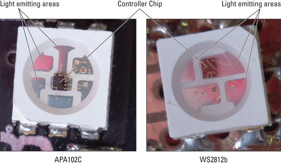
FIGURE 17-4: DotStar (APA102C) and NeoPixel (WS2812b) LEDs.
You can get NeoPixels in conventional leaded LED packages — not the surface mount type, in other words — as well as the DotStar's 5mm-square packages. Both are available as individual parts as well as long strips of LEDs. But the major difference between the two lies in how they take their commands from the computer. The NeoPixel requires one signal wire, and the DotStar requires two. Given that fact, you might be forgiven for thinking that the NeoPixels are easier to use. The problem is twofold:
- This one signal wire needs to be controlled to give a precisely timed pulse.
- The Raspberry Pi, with its Linux operating system, is not good at precise timing.
There are ways around this with the help of various libraries, but each workaround comes at a price. The library from Adafruit only works with the original Model 1 Raspberry Pi as well as the Pi Zero, and the one from Pimoroni, while working on all models of Pi, uses the hardware resources that normally generate the audio for the jack socket. (You can still get sound from the HDMI connector, but not from the audio jack because it can cause the LEDs to flash randomly.)
The DotStar requires two signals and uses the sequence of transitions that these signals make to drive the data transfer process. This is ideal for a system like the Raspberry Pi, where, because of Linux, there might be a longer-than-expected delay before the next line of your code is executed. The APA102C LEDs are wired together in a chain, as shown in Figure 17-5, with the signals regenerated by each LED. Therefore, the signals never “get tired," or, as we say in electronics, degrade.

FIGURE 17-5: Wiring of an APA102C LED chain.
Each LED has a Data In and a Data Out line as well as a Clock In and Clock Out. So the inputs of the first chip are all that is connected to the GPIO pins of the Raspberry Pi. Both types of LED work on the principle that once an LED has received and stored its own data, any further data it receives is passed on to the next LED. So, after the first set of data is sent to the first LED, there has to be some sort of reset condition in place in order to recognize situations where new data is meant for the first LED and is not just data for LEDs further down the chain. This reset is done by pausing the data stream for greater than 50uS (micro seconds) on the WS2812b LEDs and by sending a stream of start and end pulses in the case of the APA102C LEDs. (The wiring of the WS2812b is very similar to the wiring of the APA102C except that there’s only one data wire in and out.)
Figure 17-6 shows the timing diagram for each type of LED — a picture of how a logic signal will change in order to indicate logic one, logic zero or the end of a data set.

FIGURE 17-6: Timing diagrams for the WS2812b and APA102C LEDs.
For the WS2812b, in order for the single wire to write a Logic One to the LED, the signal wire makes a jump to a Logic One and stops there for 3.5uS before jumping down to a Logic Zero for 0.9uS. For a Logic Zero, the signal jumps to a one for 0.9uS and then drops to low for 3.5uS. This repeats until all the data has been transferred to the LEDs. The end of the data transmission is signaled by a zero being held for at least 50uS. These times have to be +/– 0.15uS to ensure correct operation.
The APA102C, on the other hand, has two signals, called clock and data, which can go at any speed. But the important point is that when the clock signal rises — transitions from a zero to a one, in other words — whatever logic level on the data input at that moment is treated as the logic input. Doing this requires nothing special about the timing; you just have to put the GPIO pins at the correct logic levels in the right order.
Programmers have a special name they use to describe implementing a protocol like this — it’s known as bit-banging. (The technical term for this protocol is SPI, or Serial Peripheral Interface.) There’s some hardware on the processor chip to do this, but it requires a specific set of pins running in one of the alternative modes. The great thing about bit-banging is that you can use any pins. Let's see how we can bit-bang this protocol on the GPIO bus.
Bit-banging the APA102C protocol
The LEDs used in our example are connected together in a string, where one LED takes its input from the output of the previous one. The first LED in the string takes its data from the Pi. Each LED along the string can be thought of as having a number or an address. When we send out data, we have to send it to all the LEDs, but we need to change the data only for those LEDs that we want to change. If the data for an individual LED is the same as last time, it will not change. That way, we can change individual LEDs by only changing data for those LEDs we want to change and leaving the data for the others, the same as last time.
The APA102C — in addition to the normal red, green, and blue PWM values, which control the brightness — has another brightness-controlling number, which controls the current down the LED. This is the equivalent of changing the resistor value. Valid brightness-control numbers here range from 0 to 31. Each LED needs data consisting of four numbers: brightness plus red, green, and blue values. This data needs to be stored in the computer in what is known as a buffer. In Python, we can implement this buffer as a list. We can then manipulate this list — change the numbers in it, in other words — to reflect what we want to see on each LED. When we’re good and ready, we fire out the whole buffer to the string of LEDs.
Let’s look at what to put in this buffer, A complete data message has a header, used to warn the LEDs that data is coming. That header consists of 32 bits of zero, which means the data GPIO pin needs to be set at zero and the clock GPIO pin needs to be pulsed up and down 32 times. Then the message data is pulled out of the list, one number at a time. This is a 32-bit number — each bit in turn is placed on the data output pin and the clock signal is set to High. When all the LEDs have been fed, another series of zeros, known as the footer, are sent. This needs to consist of a number of pulses — at least 32 plus half the number of LEDs, to be precise. The code in listing 17-2 is a fragment of code that would do this.
LISTING 17-2: Bit-Banging the Data to the LED
       io.output(da,io.LOW) # set data pin low
       for i in range(0,32): # send header
         io.output(ck, io.LOW) # pulse the clock pin
         io.output(ck, io.HIGH)
       for i in range(0,numLeds): # send data
          d = ledArray[i]     # get a single LED's worth of data
          for j in range(0,32):
            io.output(ck, io.LOW)
            if d & 0x80000000 :
              io.output(da, io.HIGH)
            else:
              io.output(da, io.LOW)
            d = d << 1
            io.output(ck, io.HIGH)
       io.output(da, io.LOW)
       for i in range(0,33+(numLeds/2)): # send footer
         io.output(ck, io.LOW)
         io.output(ck, io.HIGH)
Note that this is a fragment only and not a complete program. Note also that this code uses the shift operator (<<), which moves the data word, or pattern, one place to the right so that the next byte to send is in the most significant bit of the word. This is the same technique we show you how to use in forming the dice pattern in Chapter 16.
Creating a class
The bit-banging code is so useful that it could be included in all programs where you want to use these LEDs. However, in order to make it convenient to use, we can make this code into a class so that you don't have to keep including these lines in your own programs. This is just like the RPi.GPIO library, which is written as a class and installed in Python. You can write your own classes and have them included in the language or, as we do here, just have the class file in the same folder as the program that uses it and then call it up at the start of the program. As well as outputting the data to the GPIO pins, we can bundle other useful stuff in the class, like ways to set the brightness, set an LED's color, and set up the data buffer. These functions of a class are known as methods and can be simply invoked. Listing 17-3 shows the implementation of a bit-banging class for the APA102 LED. Save it in a file called apa102bang.py along with the other code from the rest of this chapter.
LISTING 17-3: Bit-Banging the APA102 Class
#!/usr/bin/env python3
# Class for driving APA102 LEDs
#By Mike Cook

import RPi.GPIO as io
io.setwarnings(False)

class Apa102bang(): # Define our class

    def __init__(self,numberLeds,data,clock,bright):
       self.setBrightness(bright)
       self.da = data
       self.ck = clock
       self.numLeds = numberLeds
       io.setmode(io.BCM)
       io.setup(self.ck,io.OUT)
       io.setup(self.da,io.OUT)
       io.output(self.ck, io.HIGH)
       io.output(self.da, io.HIGH)
       self.ledArray = [self.br<<24 for i in range(0,self.numLeds)]

    def setBrightness(self,brightness):
        if brightness > 31:
           brightness = 31
        if brightness < 0:
           brightness = 0
        self.br = brightness | 0xE0

    def setLed(self,pos,col):
        if pos < self.numLeds and pos >= 0:
           self.ledArray[pos] = (self.br<<24)|(col[2]<<16)|(col[1] ↩
              8)|col[0]

    def setAll(self,col):
        for i in range(0,self.numLeds):
          self.ledArray[i] = (self.br<<24)|(col[2]<<16)|(col[1] ↩
              8)|col[0]

    def show(self):
       io.output(self.da,io.LOW)
       for i in range(0,32): # send header
         io.output(self.ck, io.LOW)
         io.output(self.ck, io.HIGH)
       for i in range(0,self.numLeds):
          d = self.ledArray[i]     # send data
          for j in range(0,32):
            io.output(self.ck, io.LOW)
            if d & 0x80000000 :
              io.output(self.da, io.HIGH)
            else:
              io.output(self.da, io.LOW)
            d = d << 1
            io.output(self.ck, io.HIGH)
       io.output(self.da, io.LOW)
       for i in range(0,33+(self.numLeds>>1)): # send footer
         io.output(self.ck, io.LOW)
         io.output(self.ck, io.HIGH)
Notice how the class name is nearly the same as the filename? The only difference is that the filename is in all lowercase letters. Keeping this distinction is important because it allows classes to be recognized correctly. Each method is defined just like a function with a def statement, and the whole class is initialized with a def __init__ function. The other thing you will notice is that a lot of the variables start with self. This is to tell the compiler that this variable is one that belongs to the class itself and that these can actually have different values, if the class has more than one instance.
You can usually tell what each method will do just by looking at the function names. For example, when you use the setBrightness method, all that happens is a variable is set that you can then use to set the brightness for future LED settings. (Note that it will not affect the current brightness of all the LEDs.) You could write a method that does set the current brightness, if you want — that would involve adding the new brightness level to all LEDs in the list and calling the show method.
To see this in action, we use the Pimoroni Blinkt! LED strip, a low-cost strip of eight APA102C LEDs that fits over all 40 GPIO header pins (even though it only uses two GPIO pins in addition to power [5V] and ground). Listing 17-4 shows a program designed to use the class. (Be sure to save this to the same folder as the class file.)
LISTING 17-4: Using the APA102 Class
#!/usr/bin/env python3
#demo1 using Apa102bang class driver

import time
from apa102bang import Apa102bang

length = 8 ; brightness = 4
dataPin = 23 ; clockPin = 24 # Blinkt! wiring
leds = Apa102bang(length,dataPin,clockPin,brightness)

def main():
   print("APA102 demo - Cnt C to stop")
   while True:
       for i in range(0,8):
          leds.setLed(i,(120,0,0)) # red
          leds.show()
          time.sleep(0.06)
       time.sleep(0.6)
       for i in range(0,4):
          leds.setLed(i,(0,120,0)) # green
          leds.show()
          time.sleep(0.06)
       time.sleep(0.6)
       for i in range(4,8):
          leds.setLed(i,(0,0,120)) # blue
          leds.show()
          time.sleep(0.06)
       time.sleep(0.6)
       for i in range(0,8):
          leds.setLed(i,(0,0,0)) # black
          leds.show()
          time.sleep(0.06)
       time.sleep(0.6)

# Main program logic:
if __name__ == '__main__':
    main()
The code starts off by defining the number of LEDs you have, the brightness you want to run them at, and the pins used for the data and clock lines. These lines are determined by the way the Blinkt! is made, but these could be any two GPIO pins, if you want to experiment with more LED strips connected to the Pi. The leds variable is set to be the class reference — use this reference followed by a dot and the method's name to call up any method. The program simply sets each LED in turn to the three primary colors and back again to black. Note how in the setLED method the colors are given as three values in a tuple. It is the show method that actually displays the contents of the data buffer on the LEDs. If you don’t call this method, the LEDs do not change.
Though this is all very interesting, the results of running this program are not very spectacular — so let’s make a game with this small LED strip.
Rainbow Invaders
Rainbow Invaders plays a bit like the old Space Invaders game, only in one dimension. The alien invaders drop bombs of various colors onto your base in an attempt to destroy you, but you can neutralize these bombs by sending up a beam of the same color. You have three buttons to choose from — red, green, and blue — and pushing a button launches a beam of that color. Sounds easy, right? Not so fast. The invaders can also drop bombs of the secondary colors as well as white, so you have to press the right combination of your three buttons to generate the right color beam. If three bombs get through, then your base is destroyed. As your base gets more hits, its color changes. The higher up a bomb is when your beam hits it, the higher you score. Add a few sound effects and this is the game.
To get this game off the ground, the first thing you have to do is to build the hardware. In this case, this means adding three push buttons to the Blinkt! LED strip. Unfortunately, this is a bit trickier that it could be. This is because the LED strip takes up all the GPIO pins — even the ones it doesn't use. There are two ways round this problem: You could solder wires on the back of the Blinkt! and bring these out to your push buttons, or you could use an extender board, like the Black HAT Hack 3R or the Mini Black HAT Hack 3R. Figure 17-7 shows where to solder the wires to the back of the Blinkt!, and Figure 17-8 shows the Black HAT Hack 3R extender board.

FIGURE 17-7: Soldering wires to the back of the Blinkt! strip.
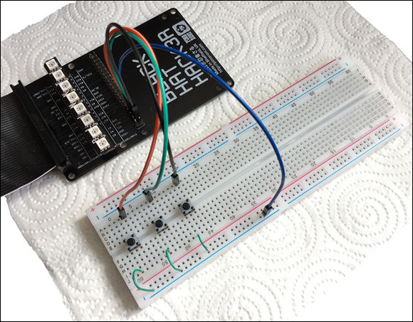
FIGURE 17-8: Black HAT Hack3R, giving two sets of GPIO pins.
Your base in the game is the righthand LED, but with the Black HAT board, you can position this LED so that your base is at the bottom of a vertical line.
We wrote the software using the Pygame framework that comes preloaded with the Pi's operating system, because it’s a great framework for handling sound effects. You should store your sound samples in a directory you create and then label sounds in the same directory as this game file. You can steal these sounds from the Scratch language: Just go to the directory /usr/share/scratch/Media/Sounds; copy the sounds ComputerBeeps2, Laser1, and Screech one at a time; and then, from the Electronic folder, put them in the sounds directory you created. Do the same for the Pop sound from the Effects folder. The code for the game is in Listing 17-5.
LISTING 17-5: Rainbow Invaders Game
#!/usr/bin/env python3
# Rainbow Invaders by Mike Cook

import RPi.GPIO as io
import pygame
import time, random
from apa102bang import Apa102bang

def main():
  global beam,gameOn,bombHeight,bombCol
  print("Rainbow Invaders")
  init()
  gameOn = True ; yourScore = 0
  bombHit = False ; bombHeight = 8
  hits = 3 ; sky.setLed(0,base[hits])
  sky.show() ; time.sleep(gameSpeed)
  nextBombMove = time.time()+gameSpeed
  bombCol = (0,0,0) ; setBombCol()
  while 1:
    while gameOn:
      if time.time()>nextBombMove:
         bombHeight -=1
         showBomb(bombHeight)
         nextBombMove = time.time()+gameSpeed
      yourScore = fireBeam(bombHeight,yourScore)
      if bombHeight == 0 :
          sky.setAll((0,0,0))
          sky.setLed(0,(255,0,0))
          sky.show() # explosion
          gameSound[3].play() # base hit
          time.sleep(2.5) # time to play
          hits -= 1
          if hits == 0:
            gameOn = False
          else:
            print("Base hit:-",hits,"from destruction")
            sky.setLed(0,base[hits])
            setBombCol()
            bombHeight = 8
      sky.show()
    print("Base destroyed:- your score",yourScore)
    time.sleep(gameSpeed * 10)
    print("Push any button for a new game")
    while io.input(fireR) and io.input(fireG) and io.input(fireB):
        pass
    print("New game starting")
    hits = 3
    gameOn = True
    bombHeight = 8
    sky.setLed(0,base[hits])
    sky.show()
    setBombCol()
    while (not io.input(fireR)) | (not io.input(fireG)) | (not ↩
      io.input(fireB)):
        pass

def getBeam():
    m = 128
    b = ((not io.input(fireR))*m,(not io.input(fireG))*m,(not io. ↩
      input(fireB))*m)
    return b

def showBeam(col,limit):
   for i in range(1,limit):
      sky.setLed(i,col)
      sky.show()
      time.sleep(0.05)

def showBomb(pos):
   global bombCol
   showBeam((0,0,0),8)
   sky.setLed(pos,bombCol)
   sky.show()

def fireBeam(far,score):
   global beam,bombCol,bombHeight
   if getBeam() != beam: # laser fire
     beam = getBeam()
     if beam != (0,0,0):
          gameSound[1].play()
     showBeam(beam,far)
     if beam == bombCol : #hit OK
       time.sleep(0.2)
       gameSound[2].play() #hit sound
       score += far
       time.sleep(1.5) # allow hit to finish
       bombHeight = 8
       setBombCol()
   return score

def setBombCol():
   global bombCol
   gameSound[0].play() # bomb incoming
   while 1 :
     r = random.randint(0,1) * 128
     g = random.randint(0,1) * 128
     b = random.randint(0,1) * 128
     if not(r==0 and g==0 and b==0) and bombCol != (r,g,b) : ↩
        break
   bombCol = (r,g,b)

def init():
   global fireR,fireG,fireB,beam,sky,gameSpeed,base,gameSound
   random.seed()
   io.setmode(io.BCM)
   fireR = 4 ; fireG = 3 ; fireB = 2
   io.setup([fireR,fireG,fireB],io.IN, pull_up_down=io.PUD_UP)
   beam = getBeam()
   length = 8 ; brightness = 4
   sky = Apa102bang(length,23,24,brightness)
   gameSpeed = 0.3 # the step speed of game in seconds
   pygame.mixer.quit()
   pygame.mixer.init(frequency=22050, size=-16, channels=2, ↩
     buffer=512)
   base = [(0,0,0),(32,0,32),(0,64,0),(0,128,128)] # base colors
   soundEffects = ["ComputerBeeps2","Laser1","Pop","Screech"]
   gameSound = [pygame.mixer.Sound("sounds/"+ ↩
   soundEffects[sound] + ".wav") ↩
                  for sound in range(0,4)]

# Main program logic:
if __name__ == '__main__':
  try:
    main()
  except KeyboardInterrupt:
    pass
# turn off all LEDs
sky.setAll((0,0,0))
sky.show()
The main function, consisting of two large loops, is where most of the action happens. The inner loop while gameOn runs a round of the game, where bombs are sent down until there have been three hits to the base — when a bomb reaches a bomb high of zero, in other words. The first if statement checks to see whether enough time has passed to move the bomb another step closer to the base. The call to the fireBeam function checks to see whether buttons are being pressed to generate a beam, and if they are, the beam is fired off and a laser sound is triggered. If the beam color matches the bomb color, then the hit sound is triggered and the current bomb height is added to your score. The round is then restarted by setting the bomb height back to 8 and a new bomb color is generated. Then the program returns to the main loop.
If a bomb is found to have reached the base, then the base is turned red and the explosion sound is triggered. The hits variable is decremented, and if it has reached zero, the round is over and the gameOn variable is set to false, thus ending the current loop. Then the final lines of the while 1 loop displays the score and waits until you have pressed a button before starting the game over again.
The array of LEDs here is called sky, which is descriptive enough, and the overall speed of the game is controlled by the gameSpeed variable in the init function. When you quit the game by pressing Ctrl and c (a Keyboard Interrupt), all LEDs are turned off to clean up the display.
You can tinker with the game speed and the number of hits your base can stand, but you can also make the game a lot harder. If you add a fourth push button, you can make this a half-brightness button. That means to match the bomb color, you have to press the right combination of red, green, and blue and also the brightness. You also need to feed this variation in brightness into the generation of the bomb color. It isn’t hard, but it does require a bit of thinking.
Keepy Uppy
Another game you can play on exactly the same hardware is Keepy Uppy, the well-known football pastime and skill demonstration where you have to keep a football in the air all the time, just by kicking it up. The ball is a moving LED, but unlike the game in the previous section, it’s a fixed color and you have to press a single button during the time when the ball is on your “foot” — the bottom LED, in other words. If you time it right, the ball moves up again until it reaches the top and then descends. A further challenge in playing is that if the player's actual button press is in the second half of the time allotted (that is, just in time), then the game speed increases, making it harder to kick the ball as soon as it can be kicked. Kick it in the first half of the allotted time and the game speed reverts to the original speed. This makes it more interesting and difficult to play. The code for the game is in Listing 17-6.
LISTING 17-6: Keepy Uppy Game
#!/usr/bin/env python3
# KeepyUppy by Mike Cook

import RPi.GPIO as io
import time, random
from apa102bang import Apa102bang
stripLength = 8

def main():
  global beam,gameOn,ballHeight,ballCol
  print("Keepy Uppy")
  init()
  gameOn = True
  ballDirection = -1; ballHeight = stripLength
  foot = 0 ; kicks = 0
  currentGameSpeed = gameSpeed
  leds.setLed(0,footCol[foot]) # foot color
  leds.show()
  time.sleep(gameSpeed)
  nextBallMove = time.time()+gameSpeed
  lastKickMade = not(io.input(kick))
  while 1:
    while gameOn:
      kickMade = not(io.input(kick))
      if kickMade and not(lastKickMade) :
        if ballHeight == 0: #   kick
           ballDirection = ballDirection * -1
           #speed up if you are late pressing
           if nextBallMove - time.time() < currentGameSpeed/2 :
             currentGameSpeed = currentGameSpeed / 2
           else:
             currentGameSpeed = gameSpeed
           nextBallMove = time.time()-1.0
           foot = 1
           kicks += 1 # add to your score
        else:
          foot = 2
      if time.time()>nextBallMove:
         leds.setLed(ballHeight,(0,0,0))
         ballHeight +=ballDirection
         leds.setLed(0,footCol[foot])
         leds.setLed(ballHeight,ballCol)
         foot = 0
         nextBallMove = time.time()+currentGameSpeed
      if ballHeight >= stripLength-1 :
         ballDirection = -1
      if ballHeight < 0: #missed the ball
         gameOn = False
      lastKickMade = kickMade
      leds.show()
    print("Ball missed your score",kicks)
    while not(io.input(kick)):
        pass
    time.sleep(gameSpeed* 5)
    print("Press kick for a new game")
    while not(io.input(kick)):
        pass
    kicks = 0
    gameOn = True
    ballHeight = stripLength
    ballDirection = -1
    leds.show()
    currentGameSpeed = gameSpeed
    while io.input(kick):
        pass

def init():
   global kick,ball,leds,gameSpeed,footCol,ballCol
   random.seed()
   io.setmode(io.BCM)
   kick = 4
   io.setup(kick,io.IN, pull_up_down=io.PUD_UP)
   brightness = 4
   dataPin = 23 ; clockPin = 24 # Blinkt! wiring
   leds = Apa102bang(stripLength,dataPin,clockPin,brightness)
   gameSpeed = 0.3 # step speed of game
   ballCol = (128,128,0)
   footCol = [(32,32,32),(128,0,0),(0,0,128)] # foot colors

# Main program logic:
if __name__ == '__main__':
  try:
    main()
  except KeyboardInterrupt:
    pass
# turn off all LEDs
leds.setAll((0,0,0))
leds.show()
Here, again like the previous program, the main structure of the code can be found in the two while loops in the main function. One issue that needs to be addressed is that the push button could just be held down so that it would register as being pressed all the time — and so always kick the ball at the right time. To prevent this from happening, you have to implement a state-change detector on the button. This involves looking at the current state of the push button and comparing it with the previously read value. Only if the previous value indicated Unpushed and the current value equals Pushed does the program recognize that the button has just become pushed. We say this is an edge detection because, rather than look at the simple state of the push button, we can detect when the state changes. (If this is drawn on a diagram, this transition looks like an edge.)
For each successful kick, you get one point added to your score, just like in the real game. The nextBallMove variable is the time the ball moves next. By subtracting the current time from this, you can tell how quickly the kick has been detected in the time period allotted to make a successful kick. This is used to speed up or restore the original speed of the ball movement.
If you want to take things further, one thing you can do is make the strip longer. The game was designed for an 8-LED strip, but simply by changing the stripLength variable at the start of the code and adding a longer strip, you can make the ball go higher. You can get much longer strips than the simple Blinkt! 8-LED strips, as you shall soon see.
LEDs Galore
The great thing about LEDs like the APA102C is that you can control lots of LEDs with just the two connections, “almost” without limit. So, before you consider projects that involve hundreds of LEDs, let’s look at some of those limits, and some ways round them.
Current limits
Current is the first and biggest limitation when trying to drive lots of LEDs. Sure, one LED only draws a small amount of current, but any small number when multiplied by a big number starts to be important. Suppose that you’re running your Raspberry Pi off a 2A power supply —roughly twice the peak current that the Pi needs. You should never take the maximum rated current out of a power supply. Instead, always keep the maximum current at about 80 percent of rated current. With a 2A power supply, that ends up being 1.6A. It is therefore reasonable to say that you have 0.6A, or 600mA (milliamps), of current capacity in a typical setup. If each LED takes 60mA, that is 20mA for each color. With that setup, you can drive a maximum of 10 LEDs with a white color at full power.
Now, APA102C LEDs are very bright and would be overpowering at close range. Luckily, there are two ways to control the brightness, and if it’s controlled, you use less current and so can drive more LEDs. The first way is to scale down the PWM values, so instead of using a value of 255 for a red, you’d simply use 128 and that will use half the current.
 Easy enough to say, but programming mistakes can easily happen and put unintended values into the PWM control. It’s also the case that using PWM doesn’t limit the peak current the LED takes — only the average current. Nevertheless, the PWM control is capable of splitting the 20mA current per LED into 78uA (microamp) steps.
A better way of controlling the brightness of the APA102C is by using the brightness control. This applies to each LED individually along with the PWM values. So far, we have just showed you how to set the brightness at a fixed level and then ignored it — this is a good strategy because it means you have a great deal of protection from programming errors. The brightness control actually limits the current through the LEDs and is controllable in 31 steps. Full current is given by a brightness value of 31, and other values of brightness give the number of 31ths of full current. So, if a single LED takes a maximum of 60mA, then with a brightness of 8, it will only take a maximum 15.48mA. So, the spare 600mA can drive 38 LEDs. Even so, a brightness of 8 is very bright when looking directly at an LED. A brightness of 2 pushes up that number to 155 LEDs and still looks good.
Anything over 155 LEDs and you will have to resort to an external power supply. It’s quite easy to use: You just supply the 5V and ground to the LEDs and make sure the ground of the power supply is connected to the ground of the Raspberry Pi.
Signals and memory
The two other limitations you have to deal with concern signals and memory. Fortunately for you, there’s no shortage of memory on the Raspberry Pi, unlike other embedded controller boards, like the Arduino. There is cause for concern, however, when it comes to signals. The Blinkt! board used earlier in this chapter connected the GPIO signals directly into the chain of LEDs. The problem is that the LEDs, because they’re powered with 5V, need a 5V logic-level signal to drive them. It just so happens that the LED's specifications state that the minimum level sufficient to be seen as a Logic One is 0.7 times the supply voltage. For a 5V supply voltage, this means a logic high of 3.5V, which is just over the 3.3 volts you get from a GPIO pin. It turns out that it does seem to work despite this, but the problem is that it isn’t guaranteed to work in all conditions and temperatures. That means a driver circuit is often included to boost the clock and data signals to 5V. This becomes more important the further away the first LED is from the Pi — and the more interference there is in the local environment from things like motors or fluorescent light fittings. Figure 17-9 shows a signal driver you can make yourself with a 74LS14 or a 74AHCT14 chip.

FIGURE 17-9: APA102C driver circuit.
Basically, this chip acts as an inverting buffer, but we don't need to invert the signals, so we just pass each signal through two buffers to keep it the right way up. As we now have a 5V signal, there’s a chance that, if the supply voltage on the LEDs drops, then a series resistor will keep the signals from damaging the first LED. There are ready-built drivers around, with most based on the 74HTC125 chip. Note the large capacitor across the external power supply. The value is not too critical, and you can make it much bigger than shown here.
Display update
Finally, you have to deal with the update question, or how fast the patterns shown by the LEDs can be changed. Using the bit-banging technique we described earlier in this chapter, it can take between 0.45 and 0.23mS to send out the data to a single LED. This time difference occurs because Linux steals time from any running program, and so the time for a refresh depends on what the operating system is doing at the moment. If this interruption occurs in that crucial time when the program is bit-banging the data out to the LEDs, then the bit banging data refresh takes longer. This means that for 144 LEDs, you can update the pattern they show about 15 times per second, at the slowest. Once updated, they require no further intervention from the Raspberry Pi until you need to update them again.
Getting more LEDs
There are various ways you can get more LEDs to play with, and perhaps the most exciting is the series of shapes you can get from the RasPiO Inspiring programmable LED boards. Shapes range from straight strips, circles, semicircles to triangles and squares. There’s also a driver board for producing the correct voltage signals and, as a bonus, a socket on this driver board allows you to plug in an analogue-to-digital converter chip. That means you can measure analogue voltages for items like control knobs and sensors. Figure 17-10 shows the triangle and straight strip.
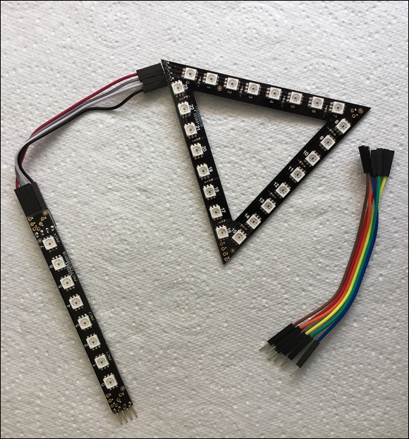
FIGURE 17-10: Some shapes from the RasPio Inspiring LED strip range.
The great thing about these shapes is that they’re easy to set up. Each strip has a plug and socket on it, for input and output, thus enabling you to easily chain together as many strips as you want. The triangle is our favorite — use two or three to make a 3D LED pyramid. In addition to working great with your Raspberry Pi, they can be used on a number of other controllers.
LED strips
Another popular way of getting lots of these LEDs already wired together is to get them on a flexible, printed circuit strip. These come in various lengths, from half a meter to 4 meters. Be sure to get the APA102 type and not the cheaper WS2812b type, to ensure that they work with all the code in this book. You can get 30, 60, or 144 LEDs per meter — as you’d expect, the cost is related to the number of LEDs. These circuit strips also come in a variety of options — black or white backing PCB, bare, coated in silicon, or in a waterproof silicon tube. You can easily cut these strips into lengths, if need be, with a sharp blade.
In addition to the RGB LED format, the APA102 comes in a white-only LED variant. These are good for domestic lighting and can be dimmed very easily.
LED matrix
One more form you can get these LEDs in is an LED matrix. Adafruit sells a number of different configurations — the biggest (and most expensive) model is a 240mm ridged disk. If that’s not what you need, you can get an 8 x 32 grid, 16 x 16 grid, or 8 x 8 grid, all on a flexible backing board. However, our favorite is a high-density 8 x 8 grid, on a ridged board. Its main feature is that, instead of using the 5 x 5mm standard LED, it uses a tiny 1.8 x 1.8mm package. That means the whole grid can be fitted into a display an inch square. These tiny LEDs only take 40mA when fully on, so they take less current than the normal-size LEDs. However, this does add up to a maximum of 2.5A. At that amount of current, the board will get quite warm as well. Nevertheless, they can be very bright, so keep the brightness down. You need to do a bit of soldering to connect the wires and the supplied capacitor to the back of the board, but these are all marked. We also wired the 5V and ground output to the 5V and ground input, to get a better power distribution on the board. This is shown in Figure 17-11.

FIGURE 17-11: Adafruit’s high-density matrix display.
Such a small matrix has many applications, one of which is to make a smart decorative broach. We thought we would like to have a go at this, and so we came up with some colorful moving-display patterns.
We’re all spoiled these days when it comes to graphics, because all their primitive functions — things like drawing lines and squares — are built into most languages. However, when faced with a display like this matrix, it is necessary to write your own.
When we address the LEDs in a strip, they’re numbered from zero to the length of the strip, and basically a matrix is just the same. However, when thinking about a matrix, it’s much more convenient to consider the x and y address of an LED; so one of the fundamental routines when driving a matrix is to convert an x / y coordinate pair into an LED number. The actual conversion involved depends on how the LED chain is bent into a matrix. The Adafruit matrix uses what is called a row bottom-up raster arrangement. The LEDs start off at zero in the lower-left of the matrix (known as the origin) and increase along the x-axis as the LED number increases. When the end of the x LEDs is reached, the next LED number is directly above the original origin. This repeats along the second row, and the third, and so on until the end of the strip. (The other fundamental way of wiring a matrix is known as a serpentine raster, where the strip zigzags up the display. You can see these two different schemes in Figure 17-12.)

FIGURE 17-12: Making a matrix with raster wiring and serpentine raster wiring.
Converting to LED numbers for the simple raster is quite easy and is given by
LedNumber = X + (Xmax * Y)
given that X and Y are the coordinates you want to get the LED number for and that Xmax is the number of LEDs in a row. Of course, this assumes that both coordinates are within the confines of the matrix. In practice, it is necessary to check the coordinates before calculating the LED number.
The serpentine raster is physically easier to wire up, but a little more complicated to work out an LED number for. This is because the preceding conversion only works on odd-numbered rows. For even-numbered rows, you need to use this:
LEDNumber = (Xmax - X - 1) + (Y * Xmax)
That means any conversion routine must first test to see if the y-coordinate is indicating an odd or even row before choosing the formula to use. This is simply done by looking at the least significant bit — the right hand most bit in the number — of the y-coordinate.
Other graphics primitives can help you draw things on a matrix. Perhaps the most fundamental is line drawing, where, given a start and an end coordinate pair, you can draw a line of lit LEDs between them. Of course, on such a small matrix, only horizontal, vertical, and 45-degree diagonal lines will look good; all other lines will be stepped, or jagged. The trick here is to work out the difference between the start and end points; the axis with the biggest difference is given an increment value of 1, with the smaller axis change given an increment value of the smaller length over the larger length. Then the x-y coordinate to plot starts off at the initial point of the line, and subsequent points are found by repeatedly adding the increments to the respective coordinates. One of the increments will be 1, and the other a fractional value. It is only when the size of this fractional coordinate exceeds a whole number that the coordinate is changed.
We implemented two other graphics primitives: the square and the filled square. In fact, the code for only an outline of a square is longer than a filled square. We could have used the line primitive to implement these two functions, but drawing horizontal and vertical lines is much quicker with a simple loop because no division operation is needed.
We made three different pattern displays that change automatically after a fixed amount of time. The program is shown in Listing 17-7.
LISTING 17-7: Matrix Broach
#!/usr/bin/env python3
# Adafruit 8X8 matrix broach

import time, random
from apa102bang import Apa102bang

dataPin = 23 ; clockPin = 24
lenX = 8 ; lenY = 8
length = lenX * lenY ; brightness = 1
half = int(length / 2)
patternDuration = 8.0
leds = Apa102bang(length, dataPin, clockPin, brightness)

def main():
   print("APA102 8 by 8 matrix broach - Cnt C to stop")
   nextChange = time.time() + patternDuration
   pattern = 1
   while True:
      if pattern == 1:
         pattern1()
      if pattern == 2:
         pattern2()
      if pattern == 3:
         pattern3()
      if time.time() > nextChange:
         nextChange = time.time() + patternDuration
         pattern +=1
         if pattern > 3:
            pattern = 1

def pattern1():
     for side in range(1,lenX):
       for i in range(0,lenX):
          square(i,i,side,randCol())
          leds.show()
          time.sleep(0.1)
       time.sleep(0.6)
       leds.setAll((0,0,0))
     leds.setAll((0,0,0))
     time.sleep(0.6)

def pattern2():
   start = 0
   for side in range(lenX-1,0,-2):
      square(start,start,side,randCol())
      leds.show()
      time.sleep(0.08)
      start += 1
   #time.sleep(0.6)
   #leds.setAll((0,0,0))

def pattern3():
   col = randCol()
   for t in range(1,8):
      line(0,0,t,0,col)
      hold()
   for t in range (1,8):
      line(0,0,8,t,col)
      hold()
   for t in range (8,0,-1):
      line(0,0,t,8,col)
      hold()
   for t in range(7,0,-1):
      line(0,0,0,t,col)
      hold()

def hold():
   leds.show()
   time.sleep(0.08)
   leds.setAll((0,0,0))

def matrix(x,y,col):
   pixel = x + y*8
   if pixel < length and x < lenX:
      leds.setLed(pixel,col)

def squareFill(x,y,side,col):
   for xp in range(x,x+side):
      for yp in range(y,y+side):
         matrix(xp,yp,col)

def square(x,y,side,col):
   for xp in range(x,x+side):
      matrix(xp,y,col)
   for xp in range(x,x+side+1):
      matrix(xp,y+side,col)
   for yp in range(y,y+side):
      matrix(x,yp,col)
   for yp in range(y,y+side):
      matrix(x+side,yp,col)

def line(xs,ys,xe,ye,col):
   xl = xe - xs
   yl = ye - ys
   if xl > yl:
      xinc = 1.0
      yinc = yl/xl
   else:
      yinc = 1.0
      xinc = xl/yl
   x= float(xs) ; y = float(ys)
   while x != xe or y != ye:
      matrix(int(x),int(y),col)
      x += xinc
      y += yinc

def randCol():
   r = 0; g =0; b=0
   while r+g+b == 0:
      r = random.randint(0,2) * 64
      g = random.randint(0,2) * 64
      b = random.randint(0,2) * 64
   return (r,g,b)

# Main program logic:
if __name__ == '__main__':
  try:
    main()
  except KeyboardInterrupt:
    pass
# turn off all LEDs
leds.setAll((0,0,0))
leds.show()
The program uses a variable called pattern to determine what to display. When it has been displayed for the time given by the patternDuration variable, the pattern value is changed. This patternDuration variable is only looked at when the pattern function returns, so long patterns like pattern1 will always complete at least one cycle of the pattern.
The three patterns use the different pattern primitives to display a sequence of patterns in random colors given by the randCol function. This function generates a mix of two levels of color for each of the three components but excludes black. The first pattern generates a sequence of squares whose lower corners are on the diagonal of the display. These squares start off small and then increase each time the diagonal is filled, until it uses an 8 x 8 square.
The next pattern displays a series of nested squares in changing colors. And the final display shows a “straight” line sweep, from the bottom corner round the display counterclockwise.
Given the fact that you’ve created a broach, it can be made into a wearable device by running it off a battery-powered Pi Zero. Or you can just have it as a desktop display. You can customize the timing of the display by adjusting the sleep times. Note that the solid square function is not used; you can add that to one of the patterns to make them more complex. However, our main hope is that you will write your own patterns and have even more of them added to the sequence.