Home Network Architecture
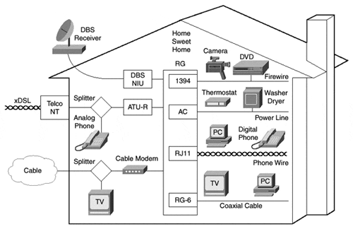
The general case of the Home Network is shown in Figure 7-2. It consists of one or more Access Networks that attach to the home at the NT.
The Home Network can be viewed as a federation of subnetworks that must be connected to each other, each of which must be connected to one or more Access Networks. These subnetworks are linked together throughout the home to form an integrated Home Network. Such subnetworks can be classified by application. There may be a Powerline subnet, a Phoneline subnet, a TV subnet, and so on. Accordingly, if a device in any particular segment wants to communicate with a device on another segment, a local packet-forwarding function is indicated.
Figure 7-2. Home Network Schematic Network Termination (NT)

The network termination (NT) is the legal and commercial demarcation point between the carrier and the consumer. This means that if something goes wrong on the carrier side of the NT, the carrier is obligated to fix it. If something goes wrong on the other side, the consumer fixes it, usually by calling the carrier, but occasionally by doing it herself. The NT is generally a passive device that performs no changes to the bits or analog signals on the line but that can provide some minimal physical-layer functions. In some cases, the NT might not exist as a discrete piece of equipment but is a virtual point at which carrier responsibility ends by agreement.
An example of the NT is the Network Interface Device (NID) used by telephone companies. The telco NID is the box on the side of the house to which the telco technician attaches phone wire from the neighborhood telephone pole.
In addition to providing a demarcation point, the NT can perform one or more of the functions detailed in the following list:
Coupling of home wiring to carrier wiring— Access wiring terminates here, and Home Network wiring begins.
Grounding— This provides an electrical ground for devices attached to the Home Network.
Lightning protection— This prevents devices on the Home Network from being damaged in the event that lightning hits the Access Network.
RF filtering— In the upstream path, low-pass filters can be installed to prevent unwanted signals generated inside the house from polluting the upstream data path.
Splitting— In the forward path, a single signal can be replicated so that multiple devices in the home can receive the same feed.
Interdiction— As an authentication measure, forward-path signals can be intercepted selectively, such as for premium television channels. When a subscriber pays for a new service, interdiction of a particular program can be lifted.
Loopback testing— To test the integrity of the Access Network (including the drop wire), the NT can provide a test mechanism whereby the carrier injects a signal into the network and receives an echo back from the customer NT. If the echo is successfully received by the carrier, the Access Network is assumed to be functioning properly.
Provisioning— For FTTH systems, the NT might be the device whereby services can be remotely provisioned by the carrier.
Splitter
A second piece of passive equipment in some architectures is the splitter. This is a prominent component of ADSL and HFC, and it performs frequency demultiplexing and replication. This device also separates the Home Network into distinct pieces, allowing each to use wiring and signaling optimized for a particular function.
In the ADSL case, the POTS splitter peels off the low-speed voice frequencies from the high-speed ADSL frequencies. Its operation is discussed in Chapter 4, "xDSL Access Networks." The result is two sets of internal wiring: one for voice and one for high-speed data. The HFC splitter creates two identical networks; all frequencies are present on both output links. Splitters introduce some frequency attenuation and distortion and are also the source of ingress noise on the upstream. However, splitters perform a useful function to reduce the cost and complexity of distributing signals throughout the home in an inexpensive manner.
Network Interface Unit
The Network Interface Unit ( NIU) is the home device that encodes and decodes bits to and from the Access Network. For HFC networks, the NIU is the cable modem. For ADSL networks, the NIU is the ATU-R.
The following list details the basic functions of the NIU:
Modulation and demodulation of signals to the Access Network
Forward error correction
Enforcement of the MAC protocol
Regulation of physical-layer-dependent control functions, such as power management in the case of HFC, or rate adaption in the case of ADSL
The NIU pairs with the access node (AN), such as the CMTS (in the case of HFC) or the DSLAM (in the case of ADSL), to enforce the MAC protocol and other control functions. For HFC, for example, the CMTS cooperates with the consumer cable modem to participate in ranging and frequency relocation.
In some cases, it is possible to package the NIU with the NT or with a more intelligent device called the Residential Gateway.
Residential Gateway
When different networks are joined—in this case, the Home Network and the Access Network—a gateway must perform the basic functions of media translation and address translation. One of the architectural options under consideration to perform these functions in the home is called the Residential Gateway (RG). Media and address translation can also be performed by the NIU, but the RG is designed for further software functions. The following list details other potential networking functions of the RG:
Packet forwarding
Media translation
Speed matching
IP address acquisition
Network address translation
MPEG and IP coexistence
Packet filtering
Authentication and encryption
System management
Some application functions of the RG are listed here:
MPEG decoder
Personal video recorder
Web browser/e-mail client
Details of RG functions listed here are discussed later in this chapter.
Set-Top Unit
After data passes through the NIU or RG, it passes to the set-top unit (STU). The STU is a device that interfaces legacy audiovisual (A/V) equipment to the broadband network. A common STU is the digital TV set-top decoder, in which the STU accepts MPEG packets from the Home Network and translates the packets for presentation on an analog TV set. If a digital TV exists, then the STU can perform other functions, such as connecting a digital camera to the Home Network or controlling an infrared remote control.
A key architectural goal is for the interface between the Home Network and the STU to be standardized to achieve cost reductions. DAVIC specifies this as the A0 interface. With a standardized A0, multiple STUs are possible in the home, each of which can service a different piece of terminal equipment.
Terminal Equipment
Terminal equipment (TE) is the generic term used to refer to televisions, personal computers, digital cameras, audio systems, and storage systems. A single Home Network has multiple pieces of TE connected to the Home Network infrastructure, which in turn suggests multiple STUs, one for each TE.
Having multiple TEs and STUs necessitates an addressing scheme within the home, as well as methods to multiplex and demultiplex traffic. TEs might be legacy devices, such as analog TV sets, or new devices specifically designed for digital home use with embedded STUs. The interface between the STU and the TE is dependent on the TE, so there is little standardization work for this interface.
