Chapter 2. Threat Models for IP Networks
In this chapter, you will learn about the following:
• Threats against IP network infrastructures
• Threats against Layer 2 switched Ethernet network infrastructures
• Threats against IP VPN network infrastructures
Knowledge of the threats against IP, Layer 2 switched Ethernet, and IP VPN network infrastructures will allow you to gain a firmer understanding of the vulnerabilities and risks associated with your network. Without a thorough understanding of the many threats, you cannot take the necessary steps to implement an effective security solution. Network design techniques to mitigate the risks are presented in Part II, “Security Techniques for Protecting IP Traffic Planes.”
Threats Against IP Network Infrastructures
IP networks and the Internet deliver a wide variety of services to consumers, businesses, and governments alike. As a result, businesses and governments are realizing unprecedented increases in productivity and effectiveness. Similarly, the Internet is changing the way individuals work, live, play, and learn. With the increased dependence on IP networks and the Internet, the potential exposure to and impact of network-based security attacks also increases. Given this trend, as a network or security operator (or both), you need to ensure that your IP network and services remain available and, in some cases, that the confidentiality and integrity of the information transmitted remains intact.
As IP networks continue to evolve, so do attack methods and threat models. IP networks and the wider Internet have experienced a paradigm shift from one of implicit trust to one of pervasive distrust. As a result, no packet can be trusted, and each packet must earn its trust through the network’s ability to classify and enforce policy. There are many forces that threaten IP infrastructures, including both natural disasters and man-made threats. Both must be considered in terms of capabilities and intent.
Natural disasters, such as earthquakes and hurricanes, are potentially significant threats. They generally strike without warning and can have devastating effects on IP infrastructures and facilities. Although a natural disaster has no intent to threaten an area, it certainly has the capability to damage and destroy.
Man-made threats may include human errors such as router misconfiguration, poor network design, or construction workers accidentally cutting through a fiber-optic cable with a backhoe. Software defects are also a significant threat because they may provide a potential attack vector or may result in the inadvertent loss of network resources such that an intended service can no longer be provided. Although not the result of malice, these threats may significantly impact the operations of an IP network and may often appear at first glance to be a malicious attack.
Conversely, a hacker, on the other hand, might have the intent to attack but not necessarily the capability to accomplish the intended act. Malicious attacks against IP infrastructures are a significant and growing threat. Many service providers (SPs) use Cisco NetFlow in conjunction with traffic anomaly detection systems, and they indicate that security attacks are an increasing part of everyday network operations. Further, the profile of an attacker has changed from mostly script-kiddies and geeks with a craze for notoriety to professional hackers interested in financial profit, espionage, and revenge. The clear distinction between human errors and malicious attacks is intent. Regardless of intent, at the end of the day and from a user’s perspective, an outage is an outage. Thus, protection against both intentional and unintentional threats must be considered. Although the target and purpose of attacks vary widely, they each aim to exploit a weakness or vulnerability within the target system. Hosts are the preferred target for worms and viruses, and compromised hosts are often used as attack launch points. Everything is a potential target, and network infrastructure such as IP routers and Ethernet switches, network services such as DNS, DHCP, and NTP, and network bandwidth (capacity) are now becoming high-value targets.
Attacks may have additional consequences beyond the intended target. This is referred to as collateral damage and demonstrates why IP traffic plane security is so critical. Within an SP network, for example, a denial-of-service (DoS) attack against one customer may trigger collateral damage that adversely affects other customers attached to the same provider edge (PE) router. Collateral damage must also be considered as a threat when evaluating vulnerabilities and mitigation techniques.
In this chapter, you will learn about the potential threats against and vulnerabilities of IP and Layer 2 Ethernet networks, as well as threats against the two most widely deployed IP VPN technologies. Techniques to mitigate these threats are reviewed in Part II. This chapter also assumes that the network is physically secure. Network-based security measures become ineffective if physical security has been breached.
Resource Exhaustion Attacks
Resource exhaustion attacks are a form of DoS attack.
Denial-of-Service Attack
A denial-of-service (DoS) attack aims to make the target unavailable for its intended service. Such attacks are often launched using a set of distributed systems or hosts, hence the term distributed DoS (DDoS). In this book, DoS refers to both distributed and nondistributed DoS attacks.
By targeting IP routers, a miscreant may adversely affect the integrity and availability of the network infrastructure, including end-to-end IP connectivity. This section reviews various DoS techniques used to attack IP routers and the specific router resource(s) commonly targeted. However, as outlined in Chapter 1, “Internet Protocol Operations Fundamentals,” router architectures vary widely from router to router; hence, platform-specific performance and scale limits relating to DoS resistance are not included in this discussion and must be considered independently per individual routing platform.
Direct Attacks
If a miscreant has IP reachability to a router or other network device, they can target it, as illustrated in Figure 2-1.
Direct attacks using packet floods are not very complex and consist only of a large volume of attack traffic addressed directly to the target router.
IP Reachability
IP host A has reachability to IP host B when it can source an IP packet destined to B and B receives and processes the packets. Such packets are neither discarded along the path from A to B nor filtered through a security policy by B once received. IP reachability is also independent of physical connectivity (in other words, local versus remote connectivity).
The characteristics and traffic profile of the packet flood required to successfully leverage a DoS attack against the target router depend upon the router’s configuration, performance, and scale limits, which vary among router platforms, as previously stated. Generally, directed packet flood attacks are intended to exhaust router resources with attack traffic. If the attack is successful, the integrity and availability of the targeted router may be adversely affected and, if repeated, the result might be a sustained DoS condition. Router resources that are commonly affected by packet flood attacks include the following:
• CPU: The CPU implements the control and management plane tasks within an IP router. In some cases, they may also be used for data plane forwarding and services plane functions. Because CPU generally serve as master controllers of the router, packet flood attacks aim to saturate them with attack traffic, causing high CPU utilization. Under these conditions, the CPU may not be able to adequately process legitimate control and management plane traffic, resulting in a DoS condition.
• Packet memory: Packet buffering is necessary during router packet processing and applies to each of the IP traffic planes and to both the receive and transmit directions. Packet buffers may fill up if the packet enqueuing rate exceeds the buffer drain rate. Once a particular memory buffer is full, any new packets may be discarded until a free memory buffer is made available. When a router’s packet buffers are exhausted, legitimate traffic is discarded, which may result in a DoS condition.
Note
Although routers serve as hosts for IP control, management, and services plane traffic, they are not optimized to process this “receive” traffic. For example, they have a limited number of IP reassembly buffers for processing IP fragments. Hence, packet flood attacks using IP fragments may saturate a router’s IP reassembly buffers, causing legitimate IP fragments to be discarded. IP reassembly is also CPU intensive. Therefore, it is considered a network design and security best practice to avoid IP fragmentation and reassembly entirely within IP routers. This topic is further discussed in Chapter 7, “Services Plane Security.” Further information on IP fragmentation and reassembly is specified in RFC 791.
• Network bandwidth: IP network topologies and architectures vary significantly from network to network. While IP routers make path forwarding decisions between sources and destinations, traffic is transported using OSI Layer 2 (L2) and Layer 1 (L1) technologies, including, but not limited to, Ethernet, Frame Relay, ATM, Serial, and POS. Although some of these L2/L1 technologies may support significant traffic capacities—for example, 10-Gbps Ethernet and 40-Gbps (OC-768c) POS—the vast majority of WAN links deployed have much lower capacity. Serial NxDS0, T1/E1, and DS-3/E-3 links are not uncommon. A packet flood attack may be engineered to saturate a network link, affecting legitimate traffic forwarding across that link and resulting in a DoS condition.
• Route memory: The primary purpose of a router is to provide IP reachability and traffic forwarding between known IP prefixes (or routes). The size of IP routing tables vary significantly among networks and routers. The size of the global Internet routing table, which makes use of classless interdomain routing (CIDR) aggregation, consists of greater than 200,000 IP prefixes. A router’s routing table, known as the Routing Information Base (RIB), and its associated forwarding table (FIB or CEF table) have bounded sizes. Advertising nonexistent destination prefixes or, alternatively, many longer (more-specific) prefixes versus a single aggregate prefix can exhaust the available routing table capacity. When this de-aggregation occurs, any new IP prefixes cannot be installed within the RIB, preventing IP reachability to those new prefixes.
• VTY lines: The router virtual terminal (VTY) lines provide remote in-band management access, including Telnet and SSH connectivity. An attack may open all configured vty lines and prevent remote management (CLI) access to the router. Loss of remote in-band access also makes troubleshooting and mitigating attacks very difficult. One typical form of this attack is the basic TCP SYN flood, which is discussed later, in the section “TCP Protocol Attacks.”
Directed packet flood attacks may be devised to target one specific IP traffic plane or network protocol (or both). A specific attack profile may be required due to IP reachability—for example, to bypass access control lists (ACL) or to ensure that the target processes the attack packets. If the target router receives attack traffic for a protocol it does not have enabled, it may simply discard the traffic with no adverse impact. One protocol that is common and integral to the IP protocol and traffic planes is ICMP (RFC 792). ICMP processing is software intensive and is commonly handled by the router CPU(s). ICMP Message Reply Types 3, 4, 5, 11, and 12, for example, require that the original packet’s IP header and 64 bits of its original payload be included within the ICMP reply. Hence, packets that require ICMP handling are generally punted from the CEF fast path to the process-level slow path for processing. For this reason, ICMP is a commonly used attack vector for resource exhaustion attacks. Examples of ICMP-based resource exhaustion attacks include flooding the target with any of the following ICMP request packets:
• ICMP Echo Request (Message Type 8)
• ICMP Timestamp Request (Message Type 13)
• ICMP Information Request (Message Type 15)
• ICMP Address Mask Request (Message Type 17, defined in RFC 950, Appendix I)
For each of the preceding ICMP requests, the router may respond with the corresponding ICMP reply, including:
• ICMP Echo Reply (Message Type 0)
• ICMP Timestamp Reply (Message Type 14)
• ICMP Information Reply (Message Type 16)
• ICMP Address Mask Reply (Message Type 18, defined in RFC 950, Appendix I)
A significant volume of received ICMP requests and sourced ICMP replies may adversely affect the CPU, packet memory, and network bandwidth of the target, potentially resulting in a DoS condition. Some ICMP messages are processed by routers by default, while others are not, and configuration commands may allow you to change the default behavior. Because router configurations vary from network to network, directed packet flood attack profiles also vary significantly, and an attack profile that may successfully cause denial of service on one target may have no impact on another target.
Given the simplicity and potentially significant impact of directed packet flood attacks, mitigation techniques are commonly deployed to prevent IP reachability of untrusted sources to IP routers. These techniques are considered a best common practice (BCP) and are reviewed in detail in Part II. The one common characteristic of a successful directed packet flood attack is IP reachability to the target (and, of course, resource exhaustion by the target). A variety of other resource exhaustion attack techniques are available to target IP routers even without direct IP reachability. These are reviewed in the following section.
Transit Attacks
Directed packet flood attacks use IP packets with a destination address of the target router. Transit packet flood attacks do not specify the target router as the IP destination address, but rather use crafted packets to trigger a DoS condition on an intermediate IP router in the forwarding path of the packet’s specified destination. That is, the intermediate router is the “target” of the attack, as illustrated in Figure 2-2.
Figure 2-2. Transit DoS Attack
Transit DoS techniques do not require IP reachability to the target; only IP reachability to the destination is required, with the target intermediate router being part of the forwarding path to the destination. Further, these attacks may be sourced from and destined to legitimate destination hosts, enabling the attack traffic to masquerade as legitimate transit traffic even though it is crafted to attack intermediate IP routers along the forwarding path between the source(s) and destination(s). Once again, if an attack is successful, the integrity and availability of the targeted routers may be adversely affected and, if repeated, may result in a sustained DoS condition. Several attacks using these techniques are described next: transit ICMP attacks, transit IP options attacks, and transit multicast attacks.
Transit ICMP Attacks
Given that ICMP is an integral part of the IP protocol, as previously described, it is often used to launch DoS attacks against IP infrastructure. In addition to the direct attacks outlined in the previous section, ICMP has been used to attack intermediate routers when direct IP reachability is not available. Transit ICMP attacks use crafted packet floods that result in significant ICMP handling on intermediate routers—the true targets of the attack. Such ICMP attack techniques targeting intermediate IP routers include:
• TTL expiry attack: This attack uses crafted transit IP packets timed to expire on the targeted intermediate router(s). As outlined in Chapter 1, the IP header of each IP packet includes a Time to Live (TTL) field that maintains the maximum lifetime of a packet. Each IP router that receives the packet decrements the IP TTL before processing and forwarding the packet downstream. After being decremented, if the TTL = 0, the router considers the packet expired and discards it. Further, per RFC 792, the router must signal to the packet source using ICMP Message Type 11 that the packet was discarded in transit due to an expired TTL. When flooded with a significant volume of TTL expiring transit packets, an intermediate router may be adversely impacted, potentially resulting in a DoS condition.
• IP unreachable attack: This attack uses a crafted packet flood that consists of IP packets that knowingly do not have IP reachability to the destination. Reachability may be prevented by an ACL filter, for example, or simply may result from the lack of a route to the destination within the FIB/CEF table. (Of course, the sender would be using a “default route” to source the packet in the first place.) If an intermediate router is unable to forward the packet, it will discard the packet and signal back to the source using the appropriate ICMP message. Typical ICMP messages in this case include: Destination Unreachable–Administratively Prohibited (Type 3, Code 13) when ACL filters are employed, or Destination Unreachable–Network Unreachable (Type 3, Code 0) when a destination IP route is not found. Again, because ICMP handling is often done within the CPU of the router, a flood of such packets may trigger a DoS condition. Note that this form of attack can also be used within a direct attack that targets a router directly using a closed protocol or TCP/UDP port, which would result in the ICMP Destination Unreachable–Protocol Unreachable (Type 3, Code 2) reply. Further, ICMP Destination Unreachable replies may provide useful network reconnaissance information, such as whether an IP (destination) host or network is “administratively” prohibited (ACL filtered) or simply unreachable (no route available). Network reconnaissance attacks are discussed further in the “Malicious Network Reconnaissance” section below.
• Other ICMP transit attacks: Both transit ICMP attacks outlined in the preceding bullets exploit ICMP reply message handling on intermediate routers. ICMP TTL Exceeded and ICMP Unreachable are only two specific examples. Similar attacks can be crafted for other ICMP reply messages. For example, ICMP Redirect (Message Type 5) and ICMP Parameter Problem reply messages can be used in similar attacks.
Note
For more information on ICMP and the different message types refer to RFC 792 and RFC 950 and the ICMP parameters documented at http://www.iana.org/assignments/icmp-parameters. Additional information on the ICMP protocol, headers, and potential attack vectors is provided in Appendix B, “IP Protocol Headers.” Attackers may attempt to exploit these ICMP attack vectors to trigger a DoS condition on a router for which they do not have direct IP reachability.
Transit IP Options Attacks
The IP header provides for various IP options as specified in RFC 791. Unlike IPv6 extension headers, IPv4 options are not widely used; most of them are deprecated by other higher-layer protocols and enhancements. IP protocols that do use IP option headers include:
• IGMPv2 (RFC 2236) and IGMPv3 (RFC 3376)
• MPLS Label Switched Path (LSP) Ping and Traceroute (RFC 4379)
• DVMRP (RFC 1075)
• RSVP (RFC 2205)
• MPLS TE (RFC 2702 and RFC 3209)
Given their limited deployment and complex processing requirements resulting from the variable-sized IP header, routers do not support CEF fast path forwarding of IP options packets. As a result, packets with IP options are punted to the Cisco IOS process-level slow path for data plane forwarding. As outlined in Chapter 1, the process-level slow path has much lower forwarding capacity than the CEF fast path, which, in general, can support full interface capacity (or line rate). Further, the process-level slow path (in other words, CPU) is also shared with the IP control, management, and, optionally, services planes. Thus, a flood of IP options packets may saturate the process-level slow path and strain router resources, potentially affecting other IP traffic planes and resulting in a DoS condition. These may be legitimate IP packets with legitimate sources and destinations, so even in the case of legitimate traffic, a DoS condition may result if proper protection mechanisms are not applied.
Slow path and fast path packet processing capacity varies by platform and configuration. In general, however, packets that include IP option headers require process-level slow path forwarding. Packets with IP options are not the only case where process-level slow path forwarding may be required. Specific IP multicast packets must also be forwarded in the process-level slow path. These IP multicast packets are discussed in the next section.
A separate class of attacks using IP options takes advantage of the strict and loose source-routing capability. In general, an attacker cannot influence the forwarding path taken by packets to a given destination. Thus, the ability to target specific intermediate routers is limited. IP options, however, provide for strict and loose source routing (RFC 791) whereby the source IP host is able to specify an explicit route it wishes the packet to traverse through the network. In order for this path to be honored, this feature must be enabled on each router along the path within the IP network. This IP option provides greater control to the attacker by allowing them to specify forwarding paths through the network, which can then be used to attack specific intermediate routers. IP source routing is enabled by default within Cisco IOS. It is common to disable IP source routing because it provides little benefit. Only DVMRP (RFC 1075) tunnels use loose source-route IP options. Alternatively, IP routing attacks are another approach to manipulate packet forwarding and are reviewed in the “Routing Protocol Threats” section below.
Transit Multicast Attacks
IP routing and forwarding operations for IP multicast packets are vastly different than for IP unicast packets. With unicast routing, traffic flows are forwarded through the network along a single path from source to destination. Further, unicast routing considers only the destination address when making its forwarding decision; it does not consider the source address.
With multicast forwarding, the source is sending traffic to an arbitrary group of hosts that is represented by a multicast group (destination) address. Multicast-enabled routers must determine which direction is the upstream direction (toward the source) and which is the downstream direction(s) (toward the receiver(s)). Forwarding paths between senders and receivers are maintained using a multicast distribution tree (MDT) per multicast group and, optionally, per source. These are referred to as (*, G) shared and (S, G) source trees, respectively, which are both represented within the multicast forwarding table illustrated in Example 2-1.
Example 2-1. IOS Sample Output from the show ip mroute Command
Router# show ip mroute
IP Multicast Routing Table
Flags: D - Dense, S - Sparse, B - Bidir Group, s - SSM Group, C - Connected,
L - Local, P - Pruned, R - RP-bit set, F - Register flag,
T - SPT-bit set, J - Join SPT, M - MSDP created entry,
X - Proxy Join Timer Running, A - Candidate for MSDP Advertisement,
U - URD, I - Received Source Specific Host Report, Z - Multicast Tunnel,
Y - Joined MDT-data group, y - Sending to MDT-data group
Timers: Uptime/Expires
Interface state: Interface, Next-Hop, State/Mode
(*, 224.0.255.3), uptime 5:29:15, RP is 192.168.37.2, flags: SC
Incoming interface: Tunnel0, RPF neighbor 10.3.35.1, Dvmrp
Outgoing interface list:
Ethernet0, Forward/Sparse, 5:29:15/0:02:57
(192.168.46.0/24, 224.0.255.3), uptime 5:29:15, expires 0:02:59, flags: C
Incoming interface: Tunnel0, RPF neighbor 10.3.35.1
Outgoing interface list:
Ethernet0, Forward/Sparse, 5:29:15/0:02:57
MDTs are created through IP routing protocols, such as PIM, as well as on-demand via sourced multicast traffic flows. When a router discovers a new multicast source, it creates state within its multicast forwarding table (in other words, mroute) and either builds or joins an MDT for the associated multicast group. Depending upon the multicast routing protocol deployed, state creation may require that the first data plane packet of each multicast traffic flow be punted to the IOS process-level for multicast control plane processing. Once the mroute forwarding entry is created, any subsequent packets within the flow will be CEF (fast path) switched through the router as opposed to slow path processed.
Hence, multicast-based attacks may attempt to exploit this behavior using many different IP sources and multicast groups to purposefully cause each attack packet to punt to the process-level control plane. Excessive multicast state creation processing may adversely affect router resources, triggering a DoS condition. Such attacks not only require multicast to be enabled on the router or network, but also require valid receivers in order to build the required MDT. Without these, any multicast traffic received may be silently discarded at the input router interface. For more multicast information, refer to the Cisco IOS Software IP Multicast Groups home page at ftp://ftpeng.cisco.com/ipmulticast/html/ipmulticast.html.
Reflection Attacks
A reflection attack is another form of DoS attack in that the source IP address of the attack packets is spoofed to match that of the intended target. The attack then transmits a flood of protocol request messages to innocent IP hosts (or broadcast addresses), which become reflectors. These reflectors simply respond to the spoofed request messages, flooding the unsuspecting victim. Using this technique, a large number of reflectors can be harnessed to collectively attack a target, as illustrated in Figure 2-3.
Figure 2-3. Reflection DoS Attack

Spoofed addresses and the use of many reflectors also make attack traceback much more difficult. Further, if the attack is distributed among many reflectors, the reflectors may not notice any adverse impact associated with the attack, whereas an attack launched via a single reflector would be noticed. Because the reflector is only required to reply to the spoofed request, any bidirectional or client/server IP protocol may be used to launch such an attack. The following are examples of reflection attacks, reported by CERT, that have used different protocols. Spoofing attacks are further discussed in the next section.
• Spoofed UDP echo requests (http://www.cert.org/advisories/CA-1996-01.html)
• Spoofed TCP SYN flooding (http://www.cert.org/advisories/CA-1996-21.html)
• Spoofed ICMP echo requests (http://www.cert.org/advisories/CA-1998-01.html)
• Spoofed DNS (Domain Name Service) queries (http://www.cert.org/incident_notes/IN-2000-04.html)
Spoofing Attacks
A spoofing attack uses packets that masquerade themselves with false data, typically the source IP address, to exploit a trusted relationship. In this way, these packets appear as if they were generated by a trusted source and, thereby, gain unauthorized privileges to a destination host or network. This enables them to target otherwise unreachable destinations (for example, bypass ACL filtering rules), intercept and manipulate data, and launch further attacks against the IP infrastructure. Given the potential impact, and the operational challenges of detecting, tracing, and mitigating these types of attacks, spoofed source attacks remain a significant threat. All of the attacks outlined in this chapter may employ spoofing techniques. Source IP address spoofing is often used to hide an attacker’s identity, to bypass authentication or poorly written ACL filters, or to prevent effective attack mitigation. Conversely, other forms of attack require advanced spoofing of both IP and upper-layer protocol parameters to successfully attack a target.
The man-in-the-middle (MiTM) attack is a well-known spoofing attack whereby the attacker intercepts a legitimate communication between two trusted hosts. The attacker then attempts to control the flow of communication, as illustrated in Figure 2-4, either to read the information being exchanged or to manipulate the information exchanged, without either participating host’s knowledge. This can be achieved if the attacker is able to spoof itself as one of the trusted hosts. Alternatively, routing protocol attacks (see “Routing Protocol Threats” later in the chapter) may be used to redirect traffic flows.
Figure 2-4. Man-in-the-Middle Attack

IP addresses that are commonly used within spoofing attacks include:
• Bogon address: A source address within the reserved IP address space that has not yet been allocated or delegated by the Internet Assigned Numbers Authority (IANA) or a delegated Regional Internet Registry (RIR).
• Martian address (“packets from Mars”): A source address that does not correspond to a destination prefix within the local IP routing table.
• Private network address: A source address that uses address space reserved by RFC 1918, RFC 3330, and RFC 3927. Private addresses are not routed within the public Internet.
The next section discusses specific TCP attacks that require advanced spoofing techniques. Techniques to mitigate spoofing attacks are reviewed in Part II.
Transport Protocol Attacks
The Internet Protocol (OSI Layer 3) provides connectionless, best-effort delivery of packets to the destination as well as fragmentation and reassembly of packets in support of network links with different maximum transmission unit (MTU) sizes. The transport layer (OSI Layer 4) provides transmission handling between host applications and the IP infrastructure, which may include connection establishment, buffering, flow control, and retransmissions. The two primary IP transport protocols in use today are User Data Protocol (UDP) and Transmission Control Protocol (TCP), defined in RFC 768 and RFC 793, respectively.
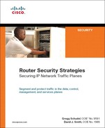
UDP is a connectionless transport layer protocol that provides no reliability, flow control, or error-recovery functions between host applications. Conversely, TCP is a connection-oriented transport layer protocol that does provide end-to-end reliable transmission, flow control, and error-recovery functions. Both are widely used by protocols within each of the IP traffic planes, as illustrated in Figure 2-5.
Figure 2-5. Example TCP- and UDP–Based IP Traffic Plane Protocols
UDP and TCP also provide for multiplexing numerous simultaneous application layer conversations over a single connection between hosts. As highlighted in Chapter 1, depending on which router is processing the packets, IP control, management, and services plane packets may appear as “transit” packets rather than “receive” packets. On intermediate routers along the downstream path, for example, these packets are treated as transit packets. Only the source and destination IP routers view ingress control, management, or services plane traffic as receive packets. This is an important distinction and is illustrated in Figure 2-6, which shows the different receive and transit treatment between IP edge and MPLS core routers, respectively. Because the core router is configured for MPLS, it is not required to run BGP. Internal BGP traffic between IP edge routers is handled as transit traffic by the core router.
Figure 2-6. Example Receive Versus Transit Control Plane Treatment

As transport layer protocols that provide transmission handling for upper-layer applications, UDP and TCP are both subject to threats such as the following:
• Attacks that hijack established sessions in order to capitalize on any previous authentication measures, enabling eavesdropping and false data injection
• DoS attacks that aim to prevent upper-layer communications between hosts
Given the fundamental differences between UDP and TCP, however, attack techniques vary significantly. Several of the more important threats against both the UDP and TCP protocols are reviewed in the following two sections. One challenge with transport protocol attacks is that they are often more difficult to detect than general DoS resource saturation attacks.
UDP Protocol Attacks
Attacking a UDP session is not highly complex because UDP itself has no authentication and is connectionless (in other words, no connection state is maintained between UDP peers). Injecting false data requires application awareness because application protocols generally apply their own authentication and integrity checks before accepting data. The potential threats against IP routing and control plane services protocols that rely on UDP for IP transport are reviewed in the “Routing Protocol Threats” and “Other IP Control Plane Threats” sections, respectively.
Launching a DoS attack against a UDP session can be achieved without application awareness. However, knowledge of the source and destination UDP port numbers, and the source and destination IP addresses, is generally required and more effective. This information is often necessary to successfully pass UDP integrity checks on the target host or target specific open UDP services. One well-known attack targets the Internet Key Exchange (IKE) protocol. IKEv1 uses UDP for transport when it performs mutual authentication and establishes security associations (SA) for IPsec. By flooding the IKE receiver with numerous bogus IKE initiation requests, the IKE resource may become depleted (in a similar way, the TCP SYN flood depletes server resources, as described in the next section). When this occurs, VPN termination devices may not allow legitimate VPN connection requests or may drop already established connections during rekeying. (IPsec VPNs are discussed further in the “IPsec VPN Threat Models” section below. Additional information on UDP, its header format, and potential security issues is provided in Appendix B.)
TCP Protocol Attacks
TCP is vastly different from UDP in that it provides connection-oriented reliable delivery of a traffic flow (RFC 793). TCP uses a number of control flags to manage the connection state, and 32-bit sequence and acknowledgment numbers to make certain that no packets are lost in transit and that the payload data is delivered to higher layers in the protocol stack at the receiving end in the correct order. TCP hosts process packets only if their sequence numbers fall within a range of unacknowledged sequence numbers defined by a “sliding window.” A TCP “reset” attack, for example, attempts to insert a TCP connection reset (RST) packet within an active TCP session by guessing a sequence number within this sliding window range in hopes of bringing down the connection.
TCP is widely used by upper-layer protocols within each of the IP traffic planes when reliable delivery is required. With or without application awareness, an attack must first successfully pass the integrity checks of TCP in order to target an established connection. Passing these checks requires spoofing source and destination IP addresses, source and destination port numbers, and the TCP sequence number. Successfully spoofing these 5-tuples enables an attacker to target an established TCP connection.
Whereas source and destination IP addresses may be relatively easy to determine and spoof, spoofing the source TCP port is often a matter of guessing. The destination TCP port is usually well known for all standard services (for example, port 23 for Telnet, port 80 for HTTP). Recent research has shown that spoofing the sequence number is easier than previously believed, as the spoofed sequence number does not have to be an exact match, but rather must simply fall within the advertised window. This significantly decreases the effort required by an attacker: the larger the window, the easier it is to manipulate the connection. If the sequence number is outside of the advertised window, or if any of the other 4-tuples are invalid, the target (receiver) should simply discard the attack packet.
Two broad families of TCP attacks generally take advantage of spoofing a TCP packet. The first is the MiTM attack (outlined earlier in the section “Spoofing Attacks”), whereby an attacker intercepts packets exchanged between the targeted hosts to learn the 5-tuples required for spoofing. With this information, the attacker might forge spoofed packets that will pass the TCP integrity checks and, thereby, allow the attacker to insert itself as a proxy between the two target hosts. This is done by resetting the original connection and then re-establishing two new connections using new sequence and acknowledgement numbers with both sides of the original connection. The second technique involves blind attacks where the attacker is not able to intercept packets between the targeted hosts. As a result, the attacker must guess the 5-tuples in order to spoof the TCP connection. If the sequence number can be compromised, attack traffic can be sent to the target.
Note
In the past, TCP hosts used simple and predictable techniques for generating initial sequence numbers. This made TCP connections more susceptible to blind attacks. Random sequence number generation is more commonly implemented within TCP stacks today, making blind attacks more difficult.
Whereas spoofing the 5-tuples is required for attacking established TCP connections, TCP hosts may also be targeted with DoS attacks that aim to exhaust system resources. Some of the common DoS threats against TCP are as follows:
• SYN flood attacks: TCP SYN floods are a type of resource saturation (DoS) attack in which the attacker sends many spoofed TCP connection requests at the target. The spoofed TCP connection requests consist of TCP packets having random source addresses and the SYN flag set that signals initial sequence number synchronization. In response, the target allocates local system resources for each spoofed request. The TCP three-way handshake is never completed for any of the requests, forcing the target’s TCP stack to maintain system resources for each outstanding connection request indefinitely. TCP stacks generally support a finite number of open connection requests. If the target receives connection requests at a higher rate than the rate at which open connection requests expire, system resources on the target may become exhausted. This prevents any valid new connection requests from being established, effectively creating a DoS condition on the target. Each TCP stack is, of course, implemented differently, and mechanisms have been integrated into many TCP stacks to protect against and minimize the impact of TCP SYN and other resource exhaustion attacks. However, these mechanisms do not make them impervious to such attacks. Note, because an SYN flood attack is not targeting an existing TCP connection, sequence number spoofing is not required. Figure 2-7 illustrates the fundamentals of the TCP SYN flood attack.
Figure 2-7. TCP SYN Flood Attack
• RST attacks: If an attacker is able to spoof the 5-tuples (as outlined earlier in the section), including the TCP sequence number, it is possible to reset an established TCP connection by sending a packet to the target with the RST or synchronize (SYN) flag set. The resulting impact on specific upper-layer protocols may vary. However, if this attack is sustained, it will result in a DoS condition. RST attacks can also be used to hijack TCP sessions, as described next.
• Session hijacking: TCP session hijacks are intended to take control of an existing TCP connection, enabling the attacker to inject false data or eavesdrop on the connection. Figure 2-8 illustrates the fundamentals of a TCP session hijacking.
Figure 2-8. TCP Session Hijacking
• ICMP attacks against TCP: TCP is subject to ICMP attacks that may cause TCP connection resets or reduce the throughput of existing connections. One interesting example involves the use of ICMP Type 3, Code 4 (Fragmentation Needed and Do Not Fragment Bit Set) error messages. TCP maintains state for established connections as outlined in the “TCP Protocol Attacks” section above. One parameter considered is the end-to-end path MTU. Certain upper-layer applications take advantage of TCP’s ability to use ICMP Type 3, Code 4 messages (which include a “suggested” MTU size) to optimize the size of transmitted packets. In this case, if an attacker can spoof an ICMP Type 3, Code 4 message targeting one end of an established TCP connection, the connection can be convinced that it should “decrease” its transmitted packet size, perhaps even down to some absurdly small value. To successfully complete such an attack, the attacker must spoof the 5-tuples of the TCP connection within the ICMP payload, because the target must correlate the spoofed ICMP packet to an existing connection.
Additional information on TCP, its header format, and potential security issues is provided in Appendix B.
This section outlined attacks specific to the UDP and TCP transport protocols. All network protocols, however, are potential attack targets. In the next section, you will see how attacks against IP routing protocols and IP control plane services in general can affect the network.
Routing Protocol Threats
A number of routing protocols are available; BGP, OSPF, IS-IS, RIPv2, and EIGRP are the most widely deployed. Each routing protocol has its own advantages and limitations. Selecting a routing protocol depends on many factors, including convergence speed, scalability, feature support, topology support, operation and maintenance, and a number of other factors that are outside the scope of this book. While several Interior Gateway Protocols (IGP) are available, BGP is the industry standard for interdomain Internet routing. Therefore, a large-scale BGP protocol attack has the potential to affect the wider Internet.
Routing protocols operate within the IP control plane and are often used as a starting point for a leveraged attack on a network. Through a routing protocol attack, an attacker can disrupt traffic or, more broadly, disrupt the routing system forwarding the traffic.
Routing System
A routing system is a collection of (IP) routers that build neighbor relationships and adjacencies to reliably exchange routing data, including destination and topology information. Information is exchanged through routing protocols that have well-defined semantics and state machines. Using these relationships and routing protocols, the routing system identifies loop-free paths through the network.
Routing protocol attacks are designed to do the following:
• Destroy the router’s or network’s ability to perform routing tasks
• Prevent new routing protocol peering and disrupt current peering
• Redirect traffic flows to inject false information, alter existing information, or remove valid information for the purposes of corrupting user data
BGP uses TCP as its transport protocol and, thus, attacks against BGP often involve the same or similar attack vectors previously described for TCP. In general, the most common are the TCP connection reset (RST) attack and the MiTM data-insertion attack. DoS attacks directly against BGP are also plausible; however, although a flood of BGP traffic may adversely impact an IP router, this is not considered a true BGP attack but rather a resource exhaustion DoS attack.
Routing protocols may also be used to attack a target by exhausting the routing table capacity, thus affecting a router’s ability to perform routing tasks, including packet forwarding and routing protocol peering. A more subtle attack is one that exploits a software implementation vulnerability—for example, using a malformed packet, which results in a routing protocol state machine violation and, consequently, a peering session failure.
Malformed Packet
A malformed packet conforms neither to the IETF Internet Protocol specifications nor to applicable vendor-proprietary protocol formats. The error may exist within the TCP/IP header or within the upper-layer protocol header—for example, ICMP, BGP, OSPF, and so on. Malformed packets are illegal and should be discarded upon receipt.
Given IP reachability, an attacker may disrupt a routing protocol peering session using the transport protocol attacks previously outlined. After all, routing protocols are simply seen by UDP and TCP as upper-layer applications.
Other routing protocol peering sessions that do not rely on TCP or UDP may also be attacked. To attack these routing protocol peering sessions, an attacker may transmit a crafted routing protocol packet from a spoofed source, thereby forcing a peering session or adjacency failure. In OSPF, for example, this can be (theoretically) achieved by spoofing an OSPF hello to the all routers address (224.0.0.5) with an empty neighbor list. Similarly with EIGRP, this can be (theoretically) achieved by sending an EIGRP update to the all routers address (224.0.0.10) with the INIT bit set. Similar attacks can be launched against the other routing protocols as well.
Attacks that cause a routing session between two routers to be torn down result in all routes advertised between these two peers to be withdrawn. When this occurs, and before the routing protocol state can be rebuilt, all of the traffic destined to prefixes whose routes have been removed is either rerouted (if an alternate path exists) or discarded (if no alternate path exists). Rerouted traffic may also introduce some congestion along these alternate paths.
Attackers may also attempt to insert bogus route updates into the routing protocol to cause traffic redirection. One purpose of this attack is to cause a routing loop, resulting in a large-scale network outage and effectively “blackholing” traffic and disrupting communications. A second purpose might be to cause traffic redirection onto insecure networks where the attacker may eavesdrop on conversations and manipulate packet content. This involves attacking the information carried within the protocol with false routing, rather than attacking the protocol peering itself. Such attacks are potentially feasible using any one of the following techniques:
• The attacker may compromise a trusted router attached to the target network, using its trusted status to inject false routing information. For more information on unauthorized access attacks, see the upcoming section “Unauthorized Access Attacks.”
• The attacker may compromise a link between two routers, and inject false data or modify data in transit. In certain topologies, this may be achieved using a MiTM attack, as outlined earlier in the “Spoofing Attacks” section.
• The attacker may spoof a valid peer and advertise false data such as invalid prefixes, invalid next hops, and invalid AS PATHs. This may be achieved using a blind spoofing attack. Further, injecting false routes may only require a single spoofed update message.
Routing protocol attacks are not specific to unicast routing protocols. Multicast routing protocols may also be targeted.
Other IP Control Plane Threats
Although routing protocols enable the IP control plane to dynamically build a forwarding path supporting the IP data plane between sources and destinations, hosts may not participate in the network until they are assigned an IP address. Similarly, a host may not communicate with other named hosts without first resolving host names into IP addresses. These essential network parameters may be assigned statically, or handled dynamically via other IP control plane applications, specifically, the Dynamic Host Configuration Protocol (DHCP) and Domain Name Service (DNS) protocols. Due to the high administrative overhead in managing these parameters through static configurations, most IP networks use DHCP and DNS.
The Network Time Protocol (NTP) is also widely deployed within IP networks to provide a clock source and synchronized timekeeping between distributed time servers and network elements. Accurate timekeeping is critically important for correlating network events (including security incidents) during troubleshooting and for quantifying network performance (including packet delay and jitter).
Threats against these IP control plane protocols include:
• DoS attacks: Because all of these protocols are UDP based, they are subject to many of the DoS, spoofing, and UDP attacks previously outlined. DoS attacks against these specific protocols also include:
— DoS attacks against the DHCP server: This attack intends to prevent clients from acquiring an IP address and other DHCP-supplied parameters, such as default gateway, IP subnet, DNS server addresses, and so on. This attack can affect hosts as they initially connect to the network, or hosts renewing DHCP leases as they expire. In this event, affected hosts lose network connectivity. DHCP servers may also be subject to resource-starvation DoS attacks where the target DHCP server is flooded with many bogus DHCP requests, each having a unique MAC address. If successful, this attack may exhaust the DHCP server address pool, preventing valid hosts from acquiring an IP address and network connectivity.
— DoS attacks against the DNS server: This attack attempts to prevent clients from translating destination host names to IP addresses, thereby affecting application connectivity. DNS (and DHCP) servers may also be leveraged for reflection attacks because they reply to any received request—legitimate or spoofed!
— DoS attacks against the NTP server: This attack attempts to prevent synchronized timekeeping among network elements, thereby affecting network event correlation and troubleshooting and network SLA measurements.
• Spoofed attacks: If an attacker is able to masquerade as a DHCP, DNS, or NTP server, the following threats exist:
— Advertisement of spoofed IP gateway information to DHCP clients enables the attacker to intercept traffic flows, facilitating MiTM attacks, eavesdropping, and the injection of false data. Information gathered from intercepted packets (for example, passwords) may also enable further attacks. The advertisement of bogus DHCP information may also prevent clients from communicating to the network, triggering a DoS condition.
— Advertisement of spoofed DNS name records (in other words, “A records”) enables the attacker to redirect traffic flows to the destination of their choice, facilitating MiTM attacks, eavesdropping, the injection of false data, and the distribution of Trojans, malware, and password/keystroke loggers. Consider the following scenario. By default, when you enter an IOS command within user or privileged (enable) EXEC mode and the command is not recognized by the IOS command interpreter, the router considers the invalid command as the host name of another device that you are attempting to connect to, for example, via Telnet or SSH. Therefore, the IOS router tries to resolve the unrecognized command into an IP address by performing an IP domain lookup via DNS. If no specific domain name server (DNS) has been explicitly configured, the router will issue a local DNS broadcast for the unrecognized command to be translated into an IP address. Such broadcasts could be used by a local attacker to gain unauthorized access to the IOS router by spoofing a DNS reply with its own IP address. The attacker will then receive the unintentional connection request and proxy it back to the router as a new inbound connection. If you enter commands or a password through this connection they will be captured by the attacker. This issue was reported to Cisco by Stephen Dugan and Jose Avila. Techniques to mitigate the risk of this threat are described in Chapter 6. Similarly to DHCP, the advertisement of bogus DNS records may also prevent clients from communicating to legitimate network resources, triggering a DoS condition. In recursive resolution environments, cache poisoning (whereby cached entries within a DNS server are deliberately contaminated) is used to cause the spoofed DNS records.
— Advertisement of spoofed NTP server messages may adversely affect timekeeping within a network, affecting network event correlation and troubleshooting, as well as network SLA measurements if applicable.
In addition to the DoS and spoofing attacks discussed, IP control plane services are also subject to unauthorized access attacks. Unauthorized access attacks are reviewed next, followed by software vulnerabilities and network reconnaissance attacks.
Unauthorized Access Attacks
IP management plane attacks that attempt to gain access to unauthorized systems and networks have long existed. These attacks pose a very serious threat. Security policies and tools often protect against external threats but not internal ones. If an attacker gains unauthorized EXEC-level CLI (command-line interface) access to a router, some of the potential threats include:
• Disabling the router (DoS) by disabling interfaces or protocols (or both)
• Changing security policies to permit further attacks, deny legitimate traffic, or disable logging, monitoring, tracing, and accounting capabilities so any other attacks go undetected
• Exposing usernames and passwords, SNMP read/write communities, protocol authentication keys (for example, MD5 passwords), and IPsec/IKE shared secrets
• Accessing network topology and IP addressing information (network reconnaissance), as well as router security and routing policies
Some of the techniques commonly used to gain unauthorized access include:
• Social engineering: A technique that manipulates people to acquire confidential information (for example, passwords).
• Physical security breeches: If physical security is compromised, other higher-layer security mechanisms may become ineffective. For example, publicly known mechanisms are available to recover passwords when physical access is available (refer to http://www.cisco.com/warp/public/474/).
• Password cracking: A variety of techniques, including brute force and dictionary attacks that attempt to guess an authentication password.
• Cyber attacks: Attempts to capture passwords or bypass authentication mechanisms through malware programs, phishing, packet sniffing, cryptanalysis, or software vulnerabilities. Software vulnerabilities are discussed further in the next section.
These techniques may be applied against any one of the available router configuration, protocol authentication, or encryption methods if IP reachability is available. Typical access points include:
• Privileged EXEC-level CLI access via enable secret, enable password, or username password
• Console CLI access via console password
• Telnet or SSH access via vty password
• Routing protocol authentication via MD5 hash
• IPsec/SSL VPN tunnel access via encryption keys
• SNMP MIB object access via SNMP read and write communities
• HTTP access via password
• FTP access via password, if FTP server is enabled
To mitigate the risk of management plane attacks, security policies often implement multiple layers of protection. In Chapter 3, “IP Network Traffic Plane Security Concepts,” you will learn about the principles of defense in depth and breadth, and how the distinction between network “core” and “edge” locations can aid in the development of appropriate security policies. Chapter 6 reviews security techniques available to protect the IP management plane.
Software Vulnerabilities
Software products inevitably have software defects; IP routers are no exception. In some instances, an IP router software defect may represent a security vulnerability that, if exploited, may compromise the confidentiality, integrity and availability of the router and IP data plane traffic. Or, the software vulnerability may affect the IP management plane, allowing an attacker to bypass authentication mechanisms, for example, and gain unauthorized access to the router. The potential threat and impact of a given vulnerability depends not only on the specific defect but also on the methods required to exploit the defect. For example, a vulnerability that can be exploited only locally (for example, a Layer 2 Ethernet attack, as reviewed in the upcoming section “Threats Against Layer 2 Network Infrastructures”) has limited exposure compared to vulnerabilities that can be exploited remotely via the wider Internet. Similarly, some vulnerabilities may be easily exploited via a single malformed packet, whereas others may require complex tools and advanced skills to exploit.
The potential impact of an exploit is also independent of risk factors and must be considered separately. That is, an attack that is “low risk but high impact” may be more critical than an attack that is “high risk but low impact.” The classic ping of death (PoD) attack illustrates an exploit of a known software vulnerability. The PoD attack sends a fragmented ICMP ping (echo) packet that, when reassembled, exceeds the maximum 65,535-byte limitations of IP. (This is possible due to the way fragmentation relies on an offset value in each fragment to determine where the individual fragment goes upon reassembly. Thus, on the last fragment, it is possible to combine a valid offset with a suitable fragment size such that [offset + size] > 65,535.) In older IP stacks, receiving a PoD packet would often crash the target host (due to a buffer overflow) and provided an almost trivial ability to perform a DoS attack. Most TCP/IP stack implementations have been corrected to prevent this type of attack.
Cisco IOS Software has had software vulnerabilities as well. Some of these have been discovered internally during development testing; others have been discovered in the field. However vulnerabilities are discovered, they are always resolved and disclosed by Cisco in a public forum. Published Cisco security advisories and responses are available at http://www.cisco.com/go/psirt. Some of the more well-known IOS vulnerabilities are reported in the following Cisco Security Advisories:
• “Cisco IOS Interface Blocked by IPv4 Packets” http://www.cisco.com/warp/public/707/cisco-sa-20030717-blocked.shtml
• “TCP Vulnerabilities in Multiple IOS-Based Cisco Products” http://www.cisco.com/warp/public/707/cisco-sa-20040420-tcp-ios.shtml
• “IPv6 Crafted Packet Vulnerability” http://www.cisco.com/warp/public/707/cisco-sa-20050729-ipv6.shtml
• “Crafted ICMP Messages Can Cause Denial of Service” http://www.cisco.com/warp/public/707/cisco-sa-20050412-icmp.shtml
Cisco publishes this information so that customers and partners are able to take the necessary actions, if any, to protect their networks. Attackers also have access to this same information and may use it to launch attacks. Deploying up-to-date software versions that include fixes for disclosed security vulnerabilities is highly recommended. Further, Cisco follows a responsible disclosure process for communicating product vulnerabilities with customers and partners. The Cisco Security Vulnerability Policy is available at http://www.cisco.com/en/US/products/products_security_vulnerability_policy.html. For more information on security incident handling, refer to Appendix D, “Security Incident Handling.”
Malicious Network Reconnaissance
Reconnaissance is the process of gathering information about a target. Network reconnaissance is considered malicious when it is conducted in preparation for an attack; malicious reconnaissance is normally considered the first phase of an attack and precedes the actual attack. Collecting intelligence about a target enables the attacker to identify specific security weaknesses that may be exploited as part of a future attack. Information that may be of interest and collected during network reconnaissance often includes:
• IP router platform hardware types and specific software versions deployed
• IP addressing schemes and reachable devices
• Network topology, protocols, forwarding paths, and path MTUs
• Host or router operating system and specific versions deployed via responses and/or banners received for Telnet, FTP, TCP/IP, and ICMP host queries, or scanning (for example, Nmap OS fingerprinting)
• Network services deployed (for example, DNS, DHCP, and NTP) and versions
• Usernames, passwords, and router configurations
• Remote access servers and extranet connectivity
• Network filtering capabilities (for example, ACLs, firewalls, IPS, and so on)
• Unprotected files, hosts, and network infrastructure
• Network and host monitoring systems (for example, IDS/IPS, anomaly detection systems, and so on)
Similar methods as outlined above in the “Unauthorized Access Attacks” section may be used to conduct network reconnaissance, including social engineering, physical security breaches, password cracking, and cyber attacks. Public information and information obtained via network scanning (for example, IP ping sweeps and port scans, IP traceroute, ICMP information requests, Cisco Discovery Protocol (CDP), SNMP MIBs, file retrieval via TFTP/FTP, remote login via Telnet, etc.) is also commonly used to gather intelligence about a potential target. Publicly available information may include:
• Internet DNS and BGP tools that provide IP address resolution, IP prefixes, and ASN information (for example, route servers, dig/nslookup, whois, and so on)
• Vendor product and software documentation
• Security vulnerabilities and software defects (for example, Cisco security advisories and Cisco CCO BugToolkit)
This is by no means a complete list, but does provide some insight into the many different methods used by attackers to conduct network reconnaissance.
Threats Against Layer 2 Network Infrastructures
Ethernet switches are widely deployed within enterprise and SP network infrastructures. Ethernet is also increasingly being deployed within consumer networks as it is commonly integrated in DSL/cable modems. Metro-Ethernet and Ethernet WAN (for example, VPLS, VPWS, and MPLS VPN) services are also increasing in deployment and are expected to replace traditional Frame Relay and ATM aggregation networks. Given this fact, Ethernet switches are increasingly being seen as good launch points for leveraged attacks.
Ethernet switches that incorporate Layer 3 functions are subject to the same IP threats outlined in the “Threats Against IP Network Infrastructures” section above. Ethernet switches are also subject to other, unique network attacks. Although IP and Ethernet operate at different layers of the OSI protocol stack, an attack within the Ethernet link layer (Layer 2) may adversely impact IP traffic planes. Because Ethernet frames are not IP routable, Ethernet attacks, in general, must be launched locally. That is, these attacks must be launched by devices connected directly to the specific Ethernet segment. However, given the increasing deployment of Metro-Ethernet and Layer 2 Ethernet WAN services, remote attacks are feasible. This section reviews specific threats against Layer 2 Ethernet infrastructures, including both native Layer 2 Ethernet switches and multilayer Ethernet switches. Additional information on mitigating the risk of these threats is provided in Part II. Note that physical security is also not considered here because it is considered out of scope.
CAM Table Overflow Attacks
Ethernet switches maintain content-addressable memory (CAM) lookup tables to dynamically track the MAC addresses for hosts connected to the physical switch ports, as well as associated VLAN parameters. CAM tables are populated by a dynamic source MAC address learning process. As the switch receives a frame on a switch port, it creates a CAM table entry that includes the source MAC address, switch port and VLAN parameters associated with the received frame, and a timestamp. If a duplicate entry already exists, the switch resets the timestamp. If the entry already exists but is associated with a different switch port or VLAN, the entry is updated based on the most recently received port or VLAN information and timestamp.
The CAM table is populated based on source MAC address information of received frames; CAM table forwarding lookups use the destination MAC address of received frames to determine the output port. In this way, the switch simply forwards the frame out the known port indicated by the CAM table instead of broadcasting the frame out of every switch port within the associated VLAN. When the destination MAC address is not present within the CAM table, the frame is broadcast out of every switch port within the associated VLAN. Broadcasting frames reduces available network capacity and increases the risk of broadcast storms and bridging loops.
Similar to IP route memories, CAM tables also have a fixed size. Once the CAM table on the switch is full, no new MAC address entries can be added. Only after the timestamps of entries expire will free space become available. Knowing this, an attacker may attempt to flood the network with bogus traffic sourced from many different spoofed MAC addresses in order to overflow the CAM tables of all Ethernet switches within the domain. Periodically repeating the attack prevents the bogus CAM table entries from expiring. This may result in legitimate traffic (with no associated CAM table entries) being broadcast out every switch port within the associated VLAN, greatly increasing the risk of broadcast storms and bridging loops. This attack may also be used to facilitate eavesdropping on traffic flows as frames are broadcast out of every switch port, facilitating packet capture, as illustrated in Figure 2-9.
Figure 2-9. CAM Table Overflow Attacks
MAC Spoofing Attacks
The CAM table overflow attack is predicated on MAC address spoofing as well as the attacker having local connectivity to the same Ethernet infrastructure as the target. While the CAM table overflow attack may facilitate eavesdropping on traffic flows, MAC spoofing may also be used to intercept traffic flows and modify payload information. This is possible using the following techniques:
• With local connectivity to the same Ethernet infrastructure as the target host, an attacker may spoof the target’s MAC address. The Ethernet switch will then reprogram the CAM table entry for the target MAC address with the attacker’s switch port. The attacker may now intercept frames destined to the target. Of course, when the target transmits a new frame, the CAM table will be reprogrammed with the correct switch port. An attacker may use this technique to modify intercepted frames and retransmit them to the target. Intercepting traffic flows in this way is very difficult given the synchronized timing required by the attacker to control the switch’s CAM table entry of the target. Nevertheless, intercepting a limited number of frames may be sufficient to capture a username and password, for example, which may then be used to gain unauthorized access. This technique may also be used to prevent IP connectivity with spoofed destinations and, thereby, trigger a DoS condition.
• With local connectivity to the same Ethernet infrastructure as the target host, an attacker may use ARP spoofing to intercept IP traffic flows. ARP (Address Resolution Protocol) provides a mechanism to resolve a MAC address to an IP address in order to provide IP connectivity within a Layer 2 broadcast domain. Using ARP, an IP host dynamically learns the MAC address for the destination IP address or the corresponding default gateway so that the proper Layer 2 frame can be built for the Layer 2 next-hop destination. Unsolicited ARP replies (known as gratuitous ARPs, or GARPs) are used to proactively advertise MAC and IP address bindings and may be transmitted without an initial ARP request. Using an unsolicited ARP reply (or GARP), an attacker may falsely advertise a spoofed IP address. Unsolicited ARP replies are not authenticated and, by default, will overwrite the MAC and IP address bindings maintained within the target’s ARP cache. Thus, using ARP spoofing, an attacker can intercept traffic flows destined to the spoofed address.
These techniques may also be used by an attacker to launch MiTM attacks, facilitating eavesdropping or the insertion of false application data. Further, these techniques may also be used to launch a DoS attack against the target and prevent IP connectivity with spoofed destinations, as illustrated in Figure 2-10.
Figure 2-10. ARP Spoofing Attacks

VLAN Hopping Attacks
VLAN hopping attacks are malicious schemes that enable an attacker on one VLAN to obtain unauthorized access to hosts on other VLANs within the same switched Ethernet domain. This is possible using the following techniques:
• Switch spoofing: Switch spoofing attacks may be launched from switch ports enabled for dynamic trunking. Switch spoofing requires an attacker to masquerade as a switch, and transmit spoofed trunked packets, which may result in the switch port being reconfigured as a VLAN trunk port. If the port is compromised and becomes a VLAN trunk port, an attacker may gain unauthorized membership to all VLANs within the switched domain, allowing attacks to be launched against other VLANs simply by transmitting spoofed 802.1Q or Cisco ISL tagged frames. Further, because the attacker appears as a valid switch with a trunk port, they may be able to both receive and transmit traffic with any IP device that is reachable through any VLAN configured on the compromised trunk port, as illustrated in Figure 2-11.
Figure 2-11. Switch Spoofing Attack

• Double tagging: Double tagging attacks transmit (attack) frames with two 802.1Q headers in an attempt to forward frames to another VLAN. VLAN tagging rules are defined by Cisco ISL or IEEE 802.1Q. ISL is a Cisco proprietary VLAN encapsulation format. The 802.1Q VLAN encapsulation format was defined by the IEEE standards organization. Unlike the Cisco ISL protocol, IEEE 802.1Q defines a native VLAN for backward compatibility, enabling 802.1Q-capable 802.3 ports to communicate with non-802.1Q-capable 802.3 ports directly by sending and receiving untagged traffic. The native VLAN is not explicitly associated to any VLAN tag on an 802.1Q link and is used for all untagged traffic received on any 802.1Q-capable port. Although the native VLAN provides backward compatibility, it may be used as an attack vector because frames associated with the native VLAN are not tagged when transmitted over any 802.1Q trunk within the switched domain. Consider the following scenario, illustrated in Figure 2-12:
Figure 2-12. Double 802.1Q Encapsulation Attack
If the switch port through which an attacker has network connectivity is configured with the VLAN that is also used as the native VLAN on 802.1Q trunk ports within the switched domain, the attacker may be able to use double-encapsulated 802.1Q packets to hop across VLANs and launch attacks against other VLANs. This is made possible due to native 802.1Q VLAN handling within the switched domain. The switch that first receives the double-tagged frame first strips the outer 802.1Q tag off the frame and broadcasts it out ports also configured with the native VLAN. The frame is broadcast because the destination MAC is not known to the native VLAN. This results in the downstream switch receiving the frame with a single 802.1Q tag. The downstream switch then forwards the packet based on the original inner 802.1Q VLAN identifier of the frame. As illustrated in Figure 2-12, this enables an attacker to hop across and launch attacks against other VLANs. As previously noted, this technique works only if the attacker switch port is configured as part of the native VLAN. Further, this provides connectivity only from the attacker to other VLANs and not vice versa, because any attempt by the target to send traffic back to the attacker will be blocked by the non-native VLAN configuration of the target’s switch port.
Private VLAN Attacks
Private VLANs (PVLAN) provide Layer 2 isolation of hosts within the same VLAN and IP subnet. This is useful in situations where you need to prevent direct connectivity between hosts without placing the hosts into different IP subnets. PVLANs are often used to isolate traffic between customers within an SP server farm, for example, and reduces the consumption of IP addresses and subnets.
PVLANs work by limiting communication among switch ports within the same VLAN. Isolated switch ports within a VLAN may communicate only with promiscuous switch ports. Community switch ports may communicate only with promiscuous switch ports, as well as other ports belonging to the same community. Promiscuous switch ports may communicate with any switch port and typically connect to the default gateway IP router. By using the default gateway as a proxy, a miscreant may bypass the access restrictions of a PVLAN, facilitating attacks against isolated host(s). Using this technique, an attacker launches an attack against the target using the target’s IP address as the IP destination, but using the default gateway router’s MAC address. Upon receipt of the attack frames, the IP router simply reroutes the Ethernet encapsulated IP packets to the target’s MAC address, as llustrated in Figure 2-13. This is feasible only if the attacker specifically sets the destination MAC address of the attack frames. Otherwise, the default gateway router, by default, will not respond to ARP requests issued by the attacker because it is on the same IP subnet as the target. The default gateway assumes the two hosts have direct connectivity and is not aware that PVLANs keep them isolated. Therefore, any attempt by the target to send traffic back to the attacker will be blocked by the PVLAN configuration. Hence, this technique only allows for unidirectional traffic flow but does enable an attacker to bypass PVLAN configurations and launch attacks against isolated hosts.
Figure 2-13. Private VLAN Attack
STP Attacks
IP routing protocols are used within the IP control plane to determine forwarding paths between IP sources and destinations. The Spanning Tree Protocol (STP) serves as the control plane within Layer 2 Ethernet networks. STP prevents the creation of bridging loops within a redundant or multipath Layer 2 Ethernet network. STP achieves this by selecting one switch as a root bridge and building a loop-free path to all devices within the Layer 2 network. STP selects one forwarding path between each device and the root bridge. Redundant paths are placed in a blocked stated and may be activated only in the event that the active path fails. If an attacker spoofs STP Bridge Protocol Data Unit (BPDU) messages, the attacker may trigger STP recalculations and the reselection of the root bridge. In the event the attacker is dual-homed and elected as the root bridge, it may be able to insert itself within the forwarding path between two hosts, as illustrated in Figure 2-14. This would enable eavesdropping and the injection of false data through MiTM attacks. Further, the attacker may also introduce bridging loops, triggering a DoS condition.
Figure 2-14. Spanning Tree Protocol Attack
VTP Attacks
Similar to the spoofed STP attack, an attacker may also spoof VLAN Trunking Protocol (VTP) advertisements. VTP is a Cisco proprietary Layer 2 messaging protocol that enables network operators to centrally manage VLAN configurations within a switched Ethernet domain. As VLANs are added, deleted, or renamed, VTP propagates these configuration changes to each switch within the VTP domain. VLAN trunk ports, for example, are automatically reconfigured based on the VTP advertisements. This greatly simplifies the configuration process of the switched network. If an attacker spoofs VTP advertisements, they may be able to add, delete, or rename VLANs within the VTP domain. This may result in bridging loops and STP recalculations, both of which may trigger a DoS condition. Further, the attacker may reconfigure the VTP domain to gain unauthorized access to specific VLANs.
Threats Against IP VPN Network Infrastructures
Virtual Private Networks (VPN) offer an alternative to deploying a private network for tying together geographically dispersed corporate networks, offices, and employees with mission-critical business applications. By not having to maintain a private network, businesses can realize significant cost savings through the use of a shared VPN infrastructure. VPNs also offer rich connectivity options, often leveraging the ubiquity of the Internet to provide connectivity from anywhere.
VPNs are often categorized as either remote-access VPNs or site-to-site VPNs. Remote-access VPNs provide mobile workers with secure access to the corporate network, whereas site-to-site VPNs provide secure connectivity between branch and corporate offices. VPNs are further categorized as Layer 2 (L2) VPNs or Layer 3 (L3) VPNs based on where they operate within the OSI reference model. There is no single best choice among the available VPN technologies. The optimal VPN architecture depends on the business requirements. In fact, many businesses are best served by some combination of several VPN technologies. Common to each VPN technology, however, is the promise of secure connectivity. This section reviews the threats and security vulnerabilities against the two most widely deployed network-based L3 VPN technologies: Multiprotocol Label Switching (MPLS) and IP Security (IPsec).
MPLS VPN Threat Models
MPLS is typically offered as a site-to-site VPN service from an SP, mainly as a replacement for traditional Frame Relay or ATM networks. The SP offers business customers IP VPN connectivity between customer sites across a shared IP infrastructure. Not only is the SP IP network shared among MPLS VPN customers but it may also be shared by SP customers of other services, including, for example, Internet transit and Layer 2 VPNs. Although the SP IP network is shared, addressing and routing separation is assured between customer VPNs, and between VPNs and the SP global IP routing table. This is inherently achieved through the use of the following mechanisms, as defined by RFC 4364 (which obsoletes RFC 2547) and illustrated in Figure 2-15:
• VPN-IPv4 addressing to ensure unique addressing and routing separation between VPNs
• Virtual routing and forwarding instances (VRF) to associate VPNs to physical (or logical) interfaces on provider edge (PE) routers
• Multiprotocol BGP to exchange VPN routing information between PE routers
Figure 2-15. MPLS VPN Architecture

The privacy of an MPLS VPN is, therefore, similar to the privacy provided by traditional Layer 2 WAN infrastructures such as Frame Relay and ATM. The preceding mechanisms provide a secure boundary around and within each MPLS VPN. With no VPN or customer site in common, communication between different VPN or Internet customer sites via the SP network is not possible. RFC 4364 also categorizes the different roles of IP routers within the MPLS VPN architecture as follows:
• Customer edge (CE) routers: CE routers are logically part of a customer VPN. Each MPLS VPN site must contain one or more CE routers. Each CE router is connected, via some sort of Layer 2 network link, to one or more provider edge routers. CE routers (with the exception of carrier-supporting-carrier models, discussed further in the “Threats Against the Inter-Provider Edge” section below) use only IP routing (not MPLS) and carry only IP prefixes of the associated the VPN.
• Provider edge (PE) routers: PE routers are logically part of the SP’s network and peer at Layer 3 with both directly connected CE routers and SP core (P) routers. PE routers represent the edge of the SP IP network and carry both SP core IP prefixes as part of the global IP routing table and customer IP prefixes associated with attached customer VPNs. PE routers use both IP and MPLS for route propagation and packet forwarding with core (P) routers and use only IP with CE routers (except for carrier-supporting-carrier models per the “Threats Against the Inter-Provider Edge” section below). PE routers distribute VPN prefix information to other PE routers using M-BGP. Therefore, as part of the MPLS VPN service, the SP participates in and manages customer routing information.
• Provider (P) routers: P routers are also logically part of the SP’s network but do not peer or connect to CE routers. P routers represent the core of the SP network and connect to PE routers and other P routers only. P routers carry only SP core IP prefixes as part of the global IP routing table and have no knowledge of customer VPNs. P routers do not need to run M-BGP because they have no customer VPN knowledge. Conversely, P and PE routers share a common IGP and forward customer traffic as MPLS labeled packets.
Unlike an Internet service, an MPLS VPN service is considered trusted—hence, often few or no security measures are applied. The remaining sections review the specific threats and security vulnerabilities against each of the MPLS VPN router categories previously outlined. Note that all of the IP and Layer 2 threats previously outlined apply, in the event an attacker gains IP or Ethernet connectivity, respectively, within the customer VPN.
Threats Against the Customer Edge
Given the IP addressing and routing separation provided by MPLS VPNs, the CE router is only reachable from within the assigned customer VPN. Therefore, by default, the CE router is not susceptible to attacks sourced from outside the customer VPN. The CE router is subject to attacks only in the following scenarios:
• Internal threats: Attacks sourced from inside the customer VPN, including the IP and Layer 2 Ethernet threats previously outlined. Also, if an attacker is able to compromise the SP network infrastructure and gain unauthorized access, they may be able to execute PE and P router configuration changes, enabling unauthorized connectivity to the customer VPN and CE router, thereby facilitating internal attacks.
• External threats: Attacks sourced from outside the customer VPN. This includes attacks launched through extranet or Internet connections, which, if configured, may provide external IP reachability to the customer VPN or CE router. If the customer VPN does not include extranet or Internet connectivity, this threat does not apply. A management VPN (or extranet) is often used by the SP for management of SP managed CE routers. This enables external reachability between the SP network operations center (NOC) and managed CE routers. However, because external connectivity is provided only to the SP NOC that provides the MPLS VPN service, its trust level is the same as the underlying MPLS VPN service. Hence, only if the SP NOC or network infrastructure is compromised may an attacker gain external IP reachability to the CE router through the management VPN. Of course, if the SP NOC or network infrastructure is compromised, the attacker may be able to launch a much wider attack against the SP network, affecting many customers and services. For more information on the management VPN, refer to Chapter 6, “Management Plane Security.”
• Multi-access broadcast network threats: As outlined in the “MPLS VPN Threat Models” section above, CE and PE routers are connected via a Layer 2 network link. If this link is a multi-access Layer 2 technology such as an Ethernet switch, then each configured customer VPN must be represented by a distinct VLAN and IP subnet. Otherwise, the CE is subject to spoofed IP attacks (as is the PE). Irrespective, the attacks outlined in the “Threats Against Layer 2 Network Infrastructures” section above may also apply.
Techniques to mitigate the risk of the preceding threats are recommended, as reviewed in Part II.
Threats Against the Provider Edge
PE routers associate physical (or logical) interfaces to customer VPNs using VRFs. VRFs are statically assigned to interfaces and cannot be modified without PE router reconfiguration. Techniques are available for the PE router to dynamically select a VRF (or VPN) based on the IP source address of traffic received from the CE router or through policy-based routing (PBR); however, these are not generally recommended for site-to-site MPLS VPN services, given the threat of spoofed IP attacks, and hence are not widely deployed. Using a static VRF configuration provides complete separation between VPNs, and between VPNs and the SP global IP routing table.
VPN customer packets cannot travel outside of the assigned VPN unless the SP VPN policies explicitly allow for it. Conversely, external packets cannot be injected inside the VPN unless explicitly allowed. RFC 3032 and IETF draft-ietf-mpls-icmp-07 specify the interaction between MPLS and ICMP, and allow for core (P) router generated ICMP messages to be sent to a source IP host within a customer VPN as required, for example, ICMP Time Exceeded (Type 11) and ICMP Destination Unreachable (Type 3) due to “Fragmentation Needed and Don’t Fragment was Set” (Code 4).
With the exception of carrier-supporting-carrier configurations detailed in the “Threats Against the Inter-Provider Edge” section below, all MPLS labeled packets received on a VRF interface or a native IP interface (for example, PE-CE) not enabled for MPLS will be discarded. This prevents an attacker from injecting unauthorized packets into the VPN through the use of spoofed MPLS labels. MPLS VPNs also prevent against external attempts to hijack customer VPN routes. If a malicious or compromised CE router advertises to a PE router an IPv4 route tagged with an illegal route target (RT), the PE router will strip the illegal RT off and only advertise the PE-configured export RT list when converted to a VPN prefix and advertised within M-iBGP. Similar attempts to hijack a VPN prefix through eBGP on a native IP external interface also do not pose a risk, because these BGP prefixes use separate subsequent address family identifiers (SAFI). In summary, only a misconfiguration or software vulnerability would allow illegal VPN packets or prefixes to leak into a VPN.
Although the PE router provides routing and address separation between VPNs, it is also reachable by its IP address within each configured VPN. This makes it vulnerable to internal IP attacks sourced from within a VPN. If an Ethernet switch is used to connect the PE router with CE routers, then the Layer 2 Ethernet threats may also apply. Further, given that a PE router aggregates many customers and VPNs, an attack against the PE within one VPN may adversely affect other VPN customers. This is due to the PE router sharing its resources, including CPU, memory, and internal (uplink) interface bandwidth, among the different customer VPNs. Hence, withstanding internal attacks and unauthorized access to the SP network infrastructure, the impact of collateral damage is the most significant threat against MPLS VPNs.
The risk of this threat may increase if the PE router also delivers Internet transit services. In this scenario, an Internet attack against the PE router (or an attached Internet transit customer) may trigger collateral damage within the PE router, thereby adversely affecting VPN customers attached to the same PE router. Collateral damage may cause packet loss, which may then trigger Layer 2 or Layer 3 protocol timeouts. In this event, affected interfaces and routing protocols may fail, resulting in loss of VPN connectivity. Hence, although an MPLS VPN assures routing and addressing separation between VPNs, and between VPNs and the SP global IP routing table, collateral damage remains a very real threat. Techniques to mitigate the risk of collateral damage are available and are reviewed in Part II. Additional threats against the PE router include:
• MPLS VPN protocol threats: The MPLS VPN architecture makes use of M-BGP routing on PE routers for VPN route propagation, and LDP on PE and core (P) routers for MPLS label switch path (LSP) establishment between ingress and egress PE routers. MPLS forwarding follows the best paths selected by IP routing except when MPLS traffic engineering (TE) is used. Both M-BGP and LDP are used within the SP IP network only (except inter-provider VPNs per the “Threats Against the Inter-Provider Edge” section below). While M-BGP uses only TCP for IP transport, LDP uses UDP for peer discovery and TCP for distribution of label bindings. PE and CE routers may exchange customer prefixes using a dynamic routing protocol or static routes. Cisco IOS supports BGP, OSPF, RIPv2, and EIGRP on MPLS VPN (PE-CE) interfaces. Hence, from a control plane perspective, PE routers are subject to the same routing and transport protocol threats as outlined in the “Routing Protocol Threats” and “Transport Protocol Attacks” sections above, however, such attacks only affect the customer VPN from which they are sourced. MPLS VPNs may also be deployed using IP transport as opposed to MPLS. Instead of using the MPLS LDP label to reach the M-BGP next hop, an IP tunnel may be used. With IP tunnels, MPLS labels are still allocated and exchanged via M-iBGP for VPN prefixes and, again, used only by the PE routers. MPLS VPNs using IP tunneling are specified in RFC 4023. Security considerations of MPLS VPNs using IP tunnels are outside the scope of this book. For more information on this topic, refer to Section 8 of RFC 4032.
• IP fragmentation and reassembly threats: MPLS VPN PE routers impose an 8-byte MPLS header on all nonlocal transit traffic received from connected CE routers. Locally switched transit traffic does not require an MPLS header because the traffic remains local to the PE router and does not transit a core (P) router. Local traffic applies when two or more customer sites within the same VPN are connected to the same PE router. Nevertheless, the addition of the 8-byte MPLS header may result in IP fragmentation of transit VPN traffic. If IP fragmentation is required, a flood of transit VPN traffic may adversely affect the ingress PE router that handles IP fragmentation within its process-level (CPU) slow path. For unicast traffic, any PE fragmented IP packets will be reassembled by the destination address specified in the fragmented packets; hence, only the ingress PE is affected. Conversely, for multicast VPN (MVPN) traffic, which is encapsulated within a 24-byte GRE point-to-multipoint tunnel header (per IETF draft-rosen-vpn-mcast-08.txt) and not within an MPLS header, the egress PE may be required to reassemble the fragmented MVPN (GRE) packets because the tunnel endpoint or destination address is the egress PE. As outlined in the “Resource Exhaustion Attacks” section above, IP routers have a limited number of IP fragment reassembly buffers. Further, fragment reassembly is very CPU intensive. If PE routers are required to fragment VPN traffic or reassemble MVPN traffic, they may be used as an attack vector. Techniques are available to mitigate this risk, as reviewed in Part II. Given the different tunnel header encapsulations used for unicast and multicast VPN traffic (in other words, 8 versus 24 bytes), mitigating unicast fragmentation does not necessarily mitigate the threat of MVPN fragmentation and reassembly.
Threats Against the Provider Core
Excluding the PE router, the SP infrastructure is inherently hidden from MPLS VPN customers given VPN routing separation. Consequently, it is not possible for a VPN customer to launch direct attacks against core (P) routers due to the absence of IP reachability. Nevertheless, core (P) routers remain susceptible to the following transit attacks:
• TTL expiry attacks: The default behavior within Cisco IOS copies the IP TTL value (after receive processing) into the MPLS TTL field of any imposed labels. Per RFC 3032, the MPLS TTL field works similarly to the IP TTL in that it is decremented for each MPLS router hop. Note that the encapsulated IP TTL is not decremented by MPLS routers except on the ultimate hop popping (UHP) router, per IETF draft-ietf-mpls-icmp-07. Given the IOS default behavior of propagating the IP TTL into the MPLS TTL, it is possible for VPN customer packets to TTL expire on a core (P) router. In this event, the core (P) router discards the expired packet and generates an ICMP TTL expiry to the original source of the packet using the techniques specified in RFC 3032. By crafting VPN packets to TTL expire within the SP core, an attacker may adversely affect a core (P) router. A sustained attack may trigger a DoS condition.
Note
Within an MPLS network, ultimate hop popping (UHP) occurs when the last router along an MPLS label switch path (LSP) pops the MPLS label stack and forwards the encapsulated IP packet downstream. Within an MPLS VPN network, UHP occurs at the egress PE router. Conversely, penultimate hop popping (PHP) occurs when the next to the last router along an MPLS label switch path (LSP) pops the MPLS label stack and forwards the encapsulated IP packet downstream. PHP applies to native MPLS (not MPLS VPN) networks. The next to the last router along the MPLS LSP within a native MPLS network is referred to as the PHP router.
• IP options attacks: As detailed in the “Transit IP Options Attacks” section above, IP option packets are normally punted into the router process-level (CPU) slow path for data plane forwarding and, hence, may be used to attack transit (or intermediate) routers. VPN customer traffic with IP options are MPLS encapsulated at the ingress PE and forwarded downstream across the SP core. Core (P) routers forward packets based upon the MPLS label and do not consider the IP options header. RFC 3032 defines a Router Alert Label, which is analogous to the Router Alert IP option header. Therefore, MPLS labeled packets having the Router Alert Label as the top label will be handled within the IOS process-level (CPU) slow path of the core (P) router. A sustained flood of MPLS packets having the Router Alert Label at the top of the MPLS label stack may adversely affect core (P) routers. MPLS VPN PE routers running Cisco IOS do not impose the Router Alert Label onto the MPLS label stack for any transit VPN customer IP packets, including those having the Router Alert IP option header. This eliminates the threat of IP options attacks sourced within an MPLS VPN against core (P) routers. However, there is no IETF standard specifying IP option processing in MPLS networks. Therefore, different MPLS VPN PE routers may function differently with respect to MPLS encapsulation of IP option packets, which may introduce such an attack vector against core (P) routers. Note that VPN packets with IP Source Route option header will be MPLS label switched across the SP network provided the IP addresses specified within the Source Route option header are valid within the associated customer VPN routing table. If not, such packets will be discarded at the ingress PE.
• Attacks against SLAs: Because MPLS VPNs are primarily used for business services, traffic classes such as the following with differentiated levels of service (QoS) and service-level agreements (SLA) are commonly offered to VPN customers:
— Real-time: Targets applications such as VoIP. It offers low delay, jitter, and packet loss. Traffic associated with this class is marked with Class Selector DSCP value 5 (0x101).
— Business Data: Targets delay-sensitive data applications that are bursty in nature. This class also has a bounded delay, jitter, and loss. Traffic associated with this class is marked with Class Selector DSCP value 4 (0x100).
— Best Effort: Represents all traffic not classified as Real-time or Business Data. Delay and jitter characteristics are not specified for this class. Traffic associated with this class is marked with Class Selector DSCP value 0 (0x000).
With IP QoS mechanisms being more commonly deployed within SP networks in support of IP VPN SLAs, recoloring uniformly across the edge is necessary to prevent low-priority traffic from being treated with high priority within the SP network. This applies not only to VPN services but to all services using the shared SP infrastructure. If, for example, best-effort Internet traffic is not recolored at the network edge, it may get improperly classified within the SP network’s high-priority traffic classes, including Real-time and Business Data per the preceding examples. This may affect the SP’s ability to satisfy SLAs offered to VPN customers. Without packet recoloring at the network edge, attackers may craft packet QoS markings to launch attacks against high-priority traffic classes or steal high-priority services when not entitled to it. For more information on QoS as a security technique, refer to Chapter 4, “Data Plane Security.” Protecting QoS services is also discussed in Chapter 7.
Threats Against the Inter-Provider Edge
There are two primary components of the inter-provider MPLS VPN architecture: Carrier Supporting Carrier (CsC) and Inter-AS VPNs. CsC is a hierarchical VPN model that enables downstream service providers (DSP), or customer carriers, to interconnect their geographically dispersed IP or MPLS networks over an upstream SP’s MPLS VPN backbone. This eliminates the need for customer carriers to build and maintain their own private MPLS backbone.
Inter-AS is a peer-to-peer model that enables customer VPNs to be extended through multiple provider or multidomain networks. Using Inter-AS VPN techniques, SPs peer with one another and offer end-to-end VPN connectivity over extended geographical locations for those VPN customers who may be out of reach for a single SP. The threats against both of these inter-provider VPN technologies are described next.
Carrier Supporting Carrier Threats
Within the CsC model, customer carriers (or DSPs) may offer Internet or MPLS VPN services, or both, to their customers. The challenge in supporting this model with native MPLS VPNs is the potential number of IP prefixes that must be carried within the associated VRF table on the PE routers. Because the customer carrier is itself an SP, it may carry both the IP prefixes of its own VPN customers and the global Internet routing table if it offers Internet transit services. This potential volume of prefixes would limit the number of customers that may be supported on the PE router because VPN routes is one of the limiting factors in scaling the PE router. The CsC model reduces the number of routes carried within the CsC-PE VRF table by enabling MPLS on the CsC-PE to CsC-CE link between the backbone carrier (CsC-PE) and customer carrier (CsC-CE), as illustrated in Figure 2-16. Applying MPLS on this link eliminates the need for the customer carrier to advertise its external IP and VPN prefixes to the backbone carrier. In this way, the CsC-PE VRF table only carries the internal IP prefixes of the customer carrier.
Figure 2-16. Carrier Supporting Carrier MPLS VPN Model
Within this CsC model, the CsC-PE router is not receiving IP packets from the CsC-PE but rather MPLS labeled IP packets. Label distribution between the CsC-CE and CsC-PE may be done through either MPLS LDP (RFC 3036) or BGP+Labels (RFC 3107). Using only BGP, the CsC control plane operates similarly to native MPLS VPNs. MPLS LDP provides an alternate control plane protocol for label distribution between the CsC-CE and CsC-PE. From a security perspective, the CsC-PE is subject to the same threats as outlined in the “Threats Against the Provider Edge” section above. Similarly, the CsC-CE is subject to the same threats as outlined in the “Threats Against the Customer Edge” section above. The customer carrier (or DSP) is itself an SP and, hence, the CsC-CE is also a core (P) router from the perspective of the DSP’s customers. The potential threats against the CsC-CE as a customer carrier core (P) router depends upon whether the DSP offers Internet transit or MPLS VPN services or both. The threats associated with both of these scenarios were described in the “Threats Against IP Network Infrastructures” and “Threats Against the Provider Core” sections above.
Despite the CsC-CE forwarding and receiving MPLS labeled data plane IP packets to and from the CsC-PE router, the CsC-PE assures routing and addressing separation of the customer carrier VPN using the same techniques outlined in the “MPLS VPN Threat Models” section above including VPN-IPv4 addressing, VRF instances, and M-iBGP. The CsC-PEs also implement an automatic MPLS label spoofing avoidance mechanism that prevents the CsC-CE from using spoofed MPLS labels to transmit unauthorized packets into another customer VPN. MPLS packets with spoofed labels that are associated with another customer VPN are automatically discarded upon ingress of the CsC-PE. This is possible because, within Cisco IOS, the labels distributed from the CsC-PE to the CsC-CE using either LDP or RFC 3107 (BGP) are VRF-aware. Hence, CsC provides addressing and routing separation between VPNs equivalent to native MPLS VPNs.
Inter-AS VPN Threats
As outlined at the start of the “Threats Against the Inter-Provider Edge” section, Inter-AS VPNs are intended to expand a single customer VPN through multiple provider networks. Section 10 of RFC 4364 outlines several techniques to achieve this, which are widely known within the industry as options (a), (b), and (c). Each has trade-offs in terms of scalability, security, and service awareness. The following list reviews the security threats associated with each option and assumes that the interconnection between MPLS VPN networks is under the control of different SPs—hence, untrusted. Conversely, if both networks are within the control of one SP, then the security threats outlined may not apply because the interconnect may be considered trusted.
• Option (a): Within option (a), the ASBR router of each SP network effectively operates as a PE router. Each ASBR, however, sees the peer ASBR as a CE router. A physical (or logical) interface is used for each VPN that requires inter-provider connectivity. Each interface is then configured with the associated VRF and eBGP routing. This is also applied on both ends of the link, which results in back-to-back (or peer-to-peer) VRFs, as illustrated in Figure 2-17. The IP control and data planes of this model are identical to that of native MPLS VPNs. Hence, this model introduces no additional threats. Each SP network operates independently (no shared IGP) and only IP reachability between Inter-AS VPN sites is exchanged. SPs have no reachability into each other’s core networks. The most significant potential threat remains collateral damage and operator misconfiguration. However, the use of distinct interfaces per Inter-AS VPN facilitates resource management within the ASBR per VPN, which may limit any impact of collateral damage.
Figure 2-17. Inter-AS Option (a): Back-to-Back VRFs
• Option (b): Within option (b), the ASBR routers use a single M-eBGP session to exchange all Inter-AS customer VPN prefixes over a single interface between SPs, as illustrated in Figure 2-18. Although this improves ASBR scaling, it prevents resource management within the ASBR per VPN. Hence, there is a much greater risk with option (b) for one Inter-AS VPN to adversely impact connectivity of another. Also, because no VRF configurations are applied on the ASBR, MPLS label spoofing avoidance checks similar to CsC cannot be applied. Thus, routing and address separation between Inter-AS VPNs depends entirely on the peer SP, because VPN label spoofing avoidance techniques are not available with option (b). Given this set of issues, this model is deemed insecure for Inter-AS VPN connectivity between different SPs.
Figure 2-18. Inter-AS VPN Option (b): M-eBGP
• Option (c): Within option (c), the ASBR routers exchange only PE /32 loopback addresses and associated label information using either MPLS LDP or BGP+Labels (RFC 3107). VPN prefixes are then exchanged between route reflectors within each AS using multihop M-eBGP, as illustrated in Figure 2-19. This option requires IP reachability between each SP’s route reflectors (RR), which exposes not only the RRs but also the core networks of each peer to one another. Similar to option (b), because no VRF configurations are applied on the ASBR, MPLS label spoofing avoidance checks similar to CsC cannot be applied. Thus, routing and address separation between Inter-AS VPNs depends entirely on the peer SP, because VPN label spoofing avoidance techniques are also not available with option (c). Given this set of issues, this model is deemed insecure for Inter-AS VPN connectivity between different SPs.
Figure 2-19. Inter-AS VPN Option (c): Multihop M-eBGP
Although MPLS VPNs provide addressing and routing separation between VPNs similar to FR and ATM VPNs, they do not provide cryptographic privacy. The next section reviews IPsec and the threats against IPsec VPNs. Note that the MPLS VPN architecture is compatible with the use of cryptography on a CE-CE basis, if that is desired.
IPsec VPN Threat Models
IPsec is an alternative to MPLS VPNs for site-to-site VPN connectivity. Similar to MPLS VPNs, IPsec VPNs also operate at the network layer and are transparent to upper-layer applications. Conversely, IPsec VPNs are most often deployed as CPE-based Layer 3 VPNs, whereas MPLS VPNs are an SP edge (PE) network-based Layer 3 VPN solution. IPsec VPNs are often chosen instead of MPLS VPNs in cases where end-to-end data encryption is required. Unlike MPLS VPNs, IPsec provides mechanisms for data encryption, integrity, origin authentication, and replay protection.
Further, IPsec also supports remote-access VPNs for mobile workers. Because MPLS VPNs do not directly support a remote-access function, the termination of an IPsec tunnel into an MPLS VPN is available within Cisco IOS today and enables remote access into an MPLS VPN. The MPLS VPN architecture may also be augmented with IPsec when data encryption is required.
The IPsec protocol is based on a suite of IETF open standards developed to protect IP traffic as it travels across the Internet or a shared IP infrastructure. This is achieved using a combination of network protocols, including:
• Internet Key Exchange (IKE): Defined by RFC 2409, IKE provides a framework for negotiation of security parameters and establishment of authentication keys. IKEv2 is defined in RFC 4306.
• Encapsulating Security Payload (ESP): Defined by RFC 2406, ESP provides a framework for encrypting, authenticating, and securing the integrity of data.
• Authentication Header (AH): Defined by RFC 2402, AH provides a framework for authenticating and securing the integrity of data (without confidentiality, because no encryption is provided).
ESP supports symmetric encryption algorithms, including standard 56-bit Data Encryption Standard (DES), the more secure Triple DES (3DES), and the newest and most secure, Advanced Encryption Standard (AES). IPsec uses the IKE protocol to establish secure communication channels, or SAs, between network devices. These SAs are used as a control channel through which IKE negotiates the encryption and authentication methods, and generates shared keys for the encryption algorithms on behalf of the IPsec data plane. The IKE protocol also provides the primary authentication mechanism for IPsec, verifying the identity of the remote system before negotiating the encryption algorithm and keys. The AH protocol verifies the integrity and authenticates the origin of IPsec packets. It can also protect against reply attacks by detecting aged or duplicate packets.
As outlined previously and illustrated in Figure 2-20, IPsec is suitable for both site-to-site and remote-access VPNs. For site-to-site IPsec VPN connectivity, an IPsec-enabled VPN router or firewall will manage IPsec sessions with remote VPN sites. Conversely, for remote-access IPsec VPN connectivity, the mobile-user devices must run IPsec VPN client software. This client software initiates and manages IPsec sessions with the head-end device(s) at the central site(s).
IPsec is a highly complex protocol suite. Attacks against cryptography algorithms, such as brute force attacks for the purposes of data compromise or data insertion, are beyond the scope of this book. IPsec remains, however, subject to other forms of attack, as outlined here:
• Reconnaissance attacks: Similar to other protocols, IPsec reconnaissance attacks may be conducted against IP reachable addresses to locate IPsec gateways. Once known, other attacks may be launched against these devices. The most common approach is to port-scan for UDP port 500, the default port used by the IKE protocol in support of IPsec. Tools such as ike-scan may be used during this process, instead of standard protocol scanners, to perform OS fingerprinting on the IPsec implementation down to a vendor, and perhaps even the software version. This information can then be used to find known vulnerabilities against the specific platform and software version. For more information on ike-scan refer to http://www.nta-monitor.com/tools/ike-scan/.
• DoS attacks: IP reachability to the IPsec tunnel endpoints is required for session establishment and VPN connectivity. Attackers may use these public addresses to launch DoS attacks against the IPsec devices, including routers, firewalls, and IP hosts. A direct attack simply involves flooding the IPsec gateway with spoofed packets that may consume limited resources. IPsec devices usually handle encryption in specialized hardware accelerators, but other ancillary processes are handled directly within the device CPU. An indirect attack against IPsec might attempt to disrupt the IKE control plane, which uses UDP for transport. A well-known attack against IKEv1 involves flooding the IPsec gateway with numerous bogus IKE initiation requests, causing IKE resources to become depleted (in a similar way that a TCP SYN flood depletes server resources). When this occurs, legitimate VPN connection requests cannot be serviced, and already-established connections may be dropped during rekeying. Further, because IPsec (and IKE) depend on IP reachability, orthogonal attacks against the routing protocol infrastructure may impact the ability of both IPsec and IKE to function correctly.
• Software vulnerabilities: Similarly, attackers may use these public addresses to exploit known software vulnerabilities within IPsec code, or the underlying OS, to create a DoS condition. IPsec is complex, and it is not inconceivable that anomalous permutations in header fields or crafted packets could potentially result in a DoS condition.
• Split tunneling threats: Split tunneling occurs by configuration, when a remote-access client is permitted to exchange traffic simultaneously with both the shared (public) network and the internal (private) network without first placing all of the network traffic inside the VPN tunnel. This provides an opportunity for attackers on the shared network to compromise the remote computer and use it to gain network access to the internal network.
• Unauthorized access attacks: If the IPsec router, firewall, or host is compromised, an attacker may launch a variety of attacks. For example, if digital certificates are used, it should be possible to modify the clock on the IPsec gateway so that it believes all of the certificates are expired, potentially causing a DoS condition. (In theory, this should also be possible through NTP.) If compromised, an attacker may also be able learn the shared secrets, encryption keys, or digital certificates applied to the IPsec tunnel, potentially allowing access to data within the tunnel via an MiTM attack. Further, if compromised, an attacker may be able to modify the routing configuration to eavesdrop or modify data before it is transmitted through the encrypted tunnel. Default user accounts and passwords are often a good starting point. Software vulnerabilities may provide unauthorized access as well.
The preceding attacks are, for the most part, IPsec-specific. Attacks against unencrypted segments, such as the IP and Layer 2 Ethernet threats described in the “Threats Against IP Network Infrastructures” and “Threats Against Layer 2 Network Infrastructures” sections above, may adversely affect or compromise the data transmitted via the IPsec tunnel. Collateral damage should always be considered as a potential attack vector against any security mechanism, especially when it is as robust as IPsec. The most efficient way to attack IPsec may not be to attack it directly, but rather to attack the surrounding, less-secure infrastructure.
Summary
This chapter reviewed the many threat vectors that exist against IP networks and against Layer 2 Ethernet switches as well as network-based IP VPN protocols. In Part II, you will learn about the techniques that you can apply to mitigate these threats. It is of benefit for everyone (except attackers) to make the Internet and private IP networks as robust and as secure as possible. Security is one of the prime enablers of the new Internet economy. Without security, development of peer-to-peer, business-to-business, and real-time interactions will be impeded.
Review Questions
1 Name the seven layers identified by the OSI reference model, and briefly describe the function of each layer.
Note
For more information on the OSI reference model, refer to Internetworking Terms and Acronyms on Cisco.com: http://www.cisco.com/en/US/tech/tk1330/tsd_technology_support_technical_reference_chapter09186a00807598b4.html#wp998586.
2 Name two types of Layer 2 Ethernet attacks, and briefly describe why these attacks must be locally sourced.
3 Name a widely available computer network tool that may be used to determine intermediate routers along the forwarding path taken by packets transiting an IP network. Briefly describe how this tool works.
4 Identify a search technique that is often used by attackers to discover network hosts, and briefly describe the value it provides.
5 Describe the difference between a crafted IP packet and a malformed IP packet.
6 Identify three different DoS attack approaches, and briefly describe how each functions.
7 When a DoS attack adversely impacts users and network components beyond the intended target, this is referred to as?
8 What MPLS VPN mechanism is used to associate an IP VPN to a physical (or logical) IP interface on a PE router?
9 Which Layer 3 IP VPN technology supports both remote-access VPNs and site-to-site VPNs?
10 Name three primary reasons for an attacker to use spoofed IP source addresses?
Further Reading
Behringer, M., and M. Morrow. MPLS VPN Security. Cisco Press, 2005. ISBN: 1-58705-183-4.
Bellovin, S. “A Look Back at ‘Security Problems within the TCP/IP Protocol.’” 20th Annual Computer Security Applications Conference. (Dec. 2004): 229-249. http://www.cs.columbia.edu/~smb/papers/acsac-ipext.pdf.
Bellovin, S. “Routing Threats.” Columbia University, April 10, 2006. http://72.14.209.104/search?q=cache:cLj6O5bgUNQJ: www.cs.columbia.edu/~smb/talks/routesec-arin.ps+routing+security+attacks&hl=en&gl=us&ct=clnk&cd=10.
Bellovin, S. “Towards a TCP Security Option.” draft-bellovin-tcpsec-00. IETF, Oct. 15, 2006.
Clark, D. “Vulnerability’s of IPsec: A Discussion of Possible Weaknesses in IPsec Implementation and Protocols.” SANS Institute, March 14, 2002. http://www.sans.org/reading_room/whitepapers/vpns/760.php?portal=a207e10e552a50dba6f2fd8079afd772.
Dubrawsky, I. “Safe Layer 2 Security In-depth – Version 2.” Cisco white paper. March 2004. http://www.cisco.com/warp/public/cc/so/cuso/epso/sqfr/sfblu_wp.pdf.
Fang, L. Security Framework for Provider-Provisioned Virtual Private Networks (PPVPNs). RFC 4111. IETF, July 2005. http://www.ietf.org/rfc/rfc4111.txt.
Gont, F. “Increasing the Payload of ICMP Error Messages.” draft-gont-icmp-payload-00. IETF, Aug. 2, 2004. http://tools.ietf.org/html/draft-gont-icmp-payload-00.
Gont, F. “ICMP Attacks Against TCP.” draft-ietf-tcpm-icmp-attacks-01. IETF, Oct. 23, 2006. http://www3.tools.ietf.org/html/draft-ietf-tcpm-icmp-attacks-01.
Greene, B. R., and P. Smith. ISP Essentials. Cisco Press, 2002. ISBN: 1-58705-041-2.
Halpern, J., S. Convery, and R. Saville. “SAFE: VPN IPsec Virtual Private Networks in Depth.” Cisco white paper. March 2004. http://www.cisco.com/warp/public/cc/so/neso/sqso/safr/savpn_wp.pdf.
Householder, A., and B. King. “Securing an Internet Name Server.” CERT/CC, Aug. 2002. http://www.cert.org/archive/pdf/dns.pdf.
Lam, K., D. LeBlanc, and B. Smith. Assessing Network Security. Microsoft Press, 2004. ISBN: 0-73562-033-4.
Longstaff, T. A., J. T. Ellis, S. V. Hernan, H. F. Lipson, R. D. McMillan, L. H. Pesante, and D. Simmel. “Security of the Internet.” CERT/CC, Aug. 2002. http://www.cert.org/encyc_article/tocencyc.html.
May, C., J. Hammerstein, J. Mattson, and K. Rush. “Defense in Depth: Foundations for Secure and Resilient IT Enterprises.” CERT/CC, Sept. 2006. http://www.cert.org/archive/pdf/Defense_in_Depth092106.pdf.
Ramaiah, A., R. Stewart, and M. Dalal. “Improving TCP’s Robustness to Blind In-Window Attacks.” draft-ietf-tcpm-tcpsecure-06. IETF, Nov. 7, 2006. http://tools.ietf.org/html/draft-ietf-tcpm-tcpsecure-06.
Retana, A. “Routing Protocols Security.” Cisco Systems. Cisco Networkers 2005. Las Vegas. June 19, 2005.
Singh, B., and S. S. Sofat. “Future of Internet Security – IPSec.” SecurityDocs.com, Jan. 26, 2005. http://www.securitydocs.com/library/2926.
Tanase, M. “IP Spoofing: An Introduction.” SecurityFocus, March 11, 2003. http://www.securityfocus.com/infocus/1674.
Touch, J. “Defending TCP Against Spoofing Attacks.” draft-ietf-tcpm-tcp-antispoof-04. IETF, May 15, 2006. http://tools.ietf.org/html/draft-ietf-tcpm-tcp-antispoof-04.
Tulloch, M. “DHCP Server Security (Part 1).” WindowSecurity.com, Oct. 27, 2006. http://www.windowsecurity.com/articles/DHCP-Security-Part1.html.
Tulloch, M. “DHCP Server Security (Part 2).” WindowSecurity.com. Oct. 27, 2006. http://www.windowsecurity.com/articles/DHCP-Security-Part2.html.
Watson, P. A. “Slipping in the Window: TCP Reset Attacks.” OSVDB, Dec. 25, 2003. http://osvdb.org/reference/SlippingInTheWindow_v1.0.doc.
White, R., A. Retana, and D. Slice. Optimal Routing Design. Cisco Press, 2005. ISBN: 1-58705-187-7.
Willman, M. “NTP Security.” GIAG, Aug. 2002. http://www.giac.org/certified_professionals/practicals/gsec/2115.php.
“ICMP Parameters.” IANA. http://www.iana.org/assignments/icmp-parameters.
“IP Parameters.” IANA. http://www.iana.org/assignments/ip-parameters.
“Managed VPN – Comparison of MPLS, IPSec, and SSL Architectures.” Cisco white paper. http://www.cisco.com/en/US/netsol/ns465/networking_solutions_white_paper0900aecd801b1b0f.shtml.
“Network Security Policy: Best Practices White Paper.” (Doc. ID: 13601.) Cisco white paper. http://www.cisco.com/warp/public/126/secpol.html.
“Securing IP Multicast Services in Triple-Play and Mobile Networks.” Cisco white paper. http://www.cisco.com/en/US/products/ps6552/products_white_paper0900aecd80557fd4.shtml.
“VLAN Security White Paper.” Cisco white paper. http://www.cisco.com/en/US/products/hw/switches/ps708/products_white_paper09186a008013159f.shtml.
“VPN Architectures—Comparing MPLS and IPSec.” Cisco white paper. http://www.cisco.com/en/US/netsol/ns341/ns121/ns193/networking_solutions_white_paper09186a008009d67f.shtml.