Chapter 7. IP Services Plane Security
In this chapter, you learn about the following:
• How services plane traffic differs from data, control, and management plane traffic in terms of packet processing and forwarding
• How services plane traffic can be protected by direct packet classification and policy enforcement mechanisms
• How additional services plane security techniques that use indirect mechanisms can be used to protect signaling and other protocol-specific service support components
Chapter 1, “Internet Protocol Operations Fundamentals,” reviewed the IP traffic planes and provided an introductory explanation of how these traffic planes were processed by various hardware and software architectures. As you learned, the services plane and data plane are both defined as carrying user traffic—that is, traffic that is sourced by and destined to end stations, servers, and other nonrouting infrastructure devices. What distinguishes services plane traffic from data plane traffic is the way in which routers and other network devices must handle these packets.
For example, data plane traffic typically receives very basic processing that mainly involves best-effort, destination-based forwarding. Services plane traffic, on the other hand, typically requires additional, specialized processing above and beyond basic forwarding. In addition, it often also requires end-to-end handling across the network. Examples of services plane traffic include VPN tunneling (MPLS, IPsec, SSL, GRE, and so on), private-to-public translation (IPv6-to-IPv4, NAT, firewall, and IDS/IPS), QoS, voice and video services, and many others.
Services Plane Overview
The services plane refers to user traffic that requires specialized packet handling by network elements above and beyond the standard forwarding logic that is typically applied. That is, services plane traffic includes customer traffic that would normally be part of the data plane and that would normally appear as transit traffic to the routers without specialized handling in the normal forwarding path. However, because specialized services are applied, routers and other forwarding devices must treat these packets in a more complex manner. In some cases, packets must be punted to the slow path for CPU handling. In other cases, dedicated hardware may be required to handle services plane traffic. For example, IPsec and SSL VPNs require high-speed encryption and decryption services, which are often performed in dedicated hardware optimized for this purpose. This is just one example of how services plane traffic differs from data plane traffic. Others are covered in this chapter.
Many aspects of the services plane are heavily dependent upon unique factors such as hardware and software performance, service functions applied, and network architecture and topology. This limits the ability to provide a full range of specific security recommendations. As such, this chapter is organized in a manner that is somewhat different from Chapters 4, 5, and 6, in which you learned about specific mechanisms dedicated exclusively to the protection of their respective IP traffic plane. What you will find for the services plane is that although there are some specific mechanisms designed to protect a specific service, it is not exclusively the case that just these specific protection mechanisms are used. Instead, protection mechanisms used in securing the data plane and control plane must also be configured to provide protection for the services plane functions.
To illustrate how services plane traffic is handled in this regard, this chapter takes a detailed look at several example services plane applications and the special requirements that must be employed to secure these services. From these examples, you will see that several overarching and consistent themes are evident that lead to a set of general processes that you can use to assess and secure other services that you may find in your unique environment. In preview, these overarching themes for services plane traffic include the following:
• The IP services plane often requires specialized packet handling to implement the defined service. For example, the application of QoS markings and policing may require processing support that cannot be provided by hardware within the CEF fast path and results in forwarding performance impacts. (This is very platform dependent.) Whenever performance impacts occur, this should be an indication that protections must be deployed.
• The IP services plane often requires the use of service-specific control plane mechanisms to support the underlying service. For example, IPsec uses the IKE protocol suite for control plane support. Whenever control planes are created and maintained, this should be an indication that protections must be deployed.
• The IP services plane often involves the creation and management of state to establish and maintain the defined service. For example, firewalls create and manage state for TCP sessions passing through them. The creation and management of state always enables attack vectors that would not otherwise exist. Whenever state creation and management is required, this should be an indication that protections must be deployed.
IP services are deployed to provide specialized treatment of user packets in some way. When a service is deployed, it requires capital and operational expenses to roll out the service. Because of this, the service is built and deployed to support a defined capacity within well-defined service-level agreements (SLA). As this is the case, there are several key reasons why the IP services plane must be protected and several goals for selecting appropriate protection mechanisms. These include the following:
• Because each deployed service has finite resources to draw upon, you must ensure the integrity of the services plane such that only legitimate traffic is allowed to take advantage of a specific service type. Services plane traffic generates higher revenues than non-services traffic (as in the case of SPs) or costs more money to deploy (as in the case of enterprises). If unauthorized traffic can use these finite resources, either maliciously or unintentionally, then these resources may not be available for the intended legitimate traffic. This leads to lost revenues or the need to spend additional capital to increase capacity unnecessarily. Thus, the protection requirements here are to permit only authorized traffic to use the service and deny unauthorized traffic from using the service.
• Because services plane traffic often consumes more general-purpose shared resources (memory, CPU interrupt cycles, and so on) that are required to support all traffic planes, you must ensure both that normal data plane traffic does not consume resources to the point where the deployed services plane lacks sufficient resources to function properly, and that when multiple services are deployed, one service type does not impact any other service type. Sufficient network resources must be available during all operating conditions—normal loads, flash-crowd conditions, failover conditions, and so on—so that higher-priority services can receive proper handling, as required. In some cases, this may even be done at the expense of lower-priority traffic. Thus, the requirements here are to protect the network and router resources to support services, but also to prevent services or non-services traffic from jeopardizing the entire network infrastructure.
Note
It is important to distinguish between a secure service and securing a service. The former is something provided by MPLS or IPsec, for example, where aspects of separation, confidentiality (encryption), authentication, and data integrity are applied to specific traffic that belongs to the service. Different to this is securing a service, which is described in this chapter. This includes the things done and steps taken to prevent unauthorized traffic from using a service (theft), and to prevent the service from being rendered unavailable (DoS) to legitimate traffic. IPsec and MPLS are both examples of secure services. However, both of these secure services must themselves be secured for the reasons mentioned in the preceding list.
Finally, it is worth noting that this chapter is not intended to be a primer on the deployment of various services. In most cases, services deployment strategies and options involve complexities that in and of themselves are often the subject of entire books. Instead, this chapter provides, through examples, an illustration of how services operate within the network environment and a method by which to secure them. To accomplish this, three services are used as illustrations: QoS, MPLS VPNs, and IPsec VPNs. Important techniques are identified here, and pointers to additional references are provided for completeness.
As outlined in Chapter 3, “IP Network Traffic Plane Security Concepts,” no single technology (or technique) makes an effective security solution. In addition, not every technology is appropriate in every case, as some may only increase complexity and may actually detract from overall network security. Developing a defense in depth and breadth strategy provides an effective approach for deploying complementary techniques to mitigate the risk of security attacks when appropriate security layers are considered. The optimal techniques will vary by organization and depend on network topology, product mix, traffic behavior, operational complexity, and service requirements. The examples in this chapter illustrate the points outlined in this section and give you the background necessary to evaluate these same or any other services plane applications deployed in your network.
Quality of Service
The term quality of service (QoS) covers a wide range of mechanisms that are applied at the network edge and sometimes within the core to provide differentiated and predictable packet experiences through the network for a variety of reasons. QoS is often described as providing priority processing and access through a congested IP core network. For most modern networks, the core is typically not where congestion occurs, but rather congestion events more commonly happen at the edge. Typical service provider (SP) core networks today are built on OC192 backbones (10 Gbps), and many are scaling to OC768 (40 Gbps) core designs. The edge is typically the more interesting place when considering QoS services.
Although QoS can be applied as a service in and of itself, it is not often deployed in this manner. QoS is most frequently combined with other service offerings such as VPNs (MPLS and IPsec) to prioritize the usage of limited resources (for example, network bandwidth or encryption capacity) and to minimize delay and jitter for voice, video, and other delay-sensitive traffic. For example, a corporation may prioritize voice traffic over other traffic types across its MPLS VPN to prevent lower-priority traffic from disrupting delay sensitive VoIP traffic. In this case, SPs must deploy appropriate QoS mechanisms within the MPLS VPN network to give priority and provide bandwidth guarantees to voice traffic. In Chapter 4, “Data Plane Security,” and Chapter 5, “Control Plane Security,” you already learned about several other practical applications for QoS as data plane and control plane enforcement techniques.
To deploy QoS, you must be capable of identifying the traffic type(s) that you want prioritized, and be willing to sacrifice some traffic at the expense of the higher-priority traffic under congestion conditions. Currently, the scope of this QoS control is limited to a single administrative domain. An enterprise, for example, can control what happens within its network, but it cannot control, by itself, what happens to its traffic as it traverses external networks. In the case of an MPLS VPN, the SP network for all intents becomes an extension of the enterprise network. But since it is administratively part of the SPs domain, SLAs are often negotiated between enterprises and SP to formally define the level of service that will be delivered.
Two distinct IP QoS models are defined here: Integrated Services and Differentiated Services. These two models augment the traditional IP best-effort service model. Integrated Services (IntServ), defined in RFC 1633, is a dynamic resource reservation model based upon RSVP (RFC 2205) signaling. Differentiated Services (DiffServ), defined in RFC 2475, removes the per-flow reservations associated with RSVP and instead uses a simplified (passive) signaling mechanism of classifying individual packets based on a well-defined packet classifier (for example, IP precedence). Only the DiffServ QoS model (using IP precedence) is discussed here.
Note
RSVP is essentially the control plane for the IntServ QoS model. RSVP-based signaling uses the ROUTER-ALERT IPv4 header option to signal end-to-end QoS requirements along a path. A detailed discussion of the RSVP-based QoS model is not discussed here and is considered outside the scope of this book. However, issues and protection mechanisms related to packets with IPv4 header options have been discussed at length in previous chapters. In addition, routing protocol and other control plane protections previously described also apply to RSVP. Without protections, attacks on the RSVP signaling system could result in QoS routing malfunctions, interference of resource reservation, or even failure of QoS provisioning.
Regardless of the model implementation, without suitable protections, QoS is vulnerable to both theft of service and denial of service, which inhibits the delivery of both high- and low-priority services as well as network availability as described in Chapter 4.
This chapter is not intended to be a primer on QoS methods, deployments, and mechanisms, but rather is intended to briefly introduce the methods used to protect a QoS service. To accomplish this, a brief overview is provided that describes the important mechanisms used by the DiffServ QoS model to implement its many functions. In this way, it will become evident that design and implementation considerations must be made when deploying QoS services. Additional details on QoS implementations may be found in the Cisco Press book QoS for IP/MPLS Networks (see the “Further Reading” section), which covers QoS methods and deployment topics in thorough detail.
QoS Mechanisms
Cisco IOS uses an idealized QoS configuration model to provide consistent behavior across platforms. Even though the underlying hardware and software may differ, the end result is intended to be identical, regardless of which device is configured. Understanding exactly how QoS is implemented and how QoS policies are translated within the router will help you understand how to protect this service.
In Cisco IOS, QoS is implemented through the Modular Quality of Service CLI (MQC) command set. You first learned about MQC in Chapters 4 and 5, because it also is the basis for implementing several data and control plane security techniques. MQC itself is discussed in more detail later in this section to help you understand how to secure a QoS implementation. Prior to reviewing MQC, however, some of the basic principles of QoS must be described.
There are four main functional components required for a QoS implementation: classification, marking, policing, and queuing. Referring to Figure 7-1, which you were first introduced to in Chapter 3, you can see that the first three of these four QoS mechanisms apply to ingress and egress processing, but queuing applies only to the egress path. (Note that the Cisco 12000 family is one exception in that it implements ingress queuing in addition to egress queuing.) Functionally, each component performs its job based on seeing an individual packet, comparing it to a policy, and taking some action. Packet statistics (counters) are maintained, primarily so that rate values can be calculated, and this represents the only state involved in the QoS process. Recognizing where state is required and maintained always provides clues as to where protection is required for any service. The concept of state is most often associated with devices like stateful firewalls, which maintain significantly more state, such as per-flow inter-packet relationships for TCP sessions. In the case of QoS, packet counters are the only state maintained. But as you will see, because QoS uses these counters to compute rates that it uses as the basis for its actions, protecting the manipulation of these counters is one of the most important goals in protecting the QoS service.
Figure 7-1. Cisco IOS Feature Order of Operations
Within QoS, even though each of the four components provides its own functionality, there exists an order to their operation and some interdependency from one component to the next. Not every component is required to be deployed, but if they are not all deployed, certain trusts and assumptions must be made about the traffic. These trust relationships and interdependencies are the main focus for securing QoS services. Let’s review each of the four components.
Classification
Classification is the first step in the QoS process and involves identifying packets and comparing each against the configured DiffServ QoS policies to find matches. There is an implied assumption, of course, that some engineering effort has occurred to define policies. The process of classification affects every other step in the QoS process and thus is critical for ensuring correct QoS performance. Classification can be based on any number of items within each packet, as described in Chapter 4, such as source and destination IP address, protocol type and port, IP header precedence/DSCP setting, ingress interface, or even payload contents. The desired outcome of the packet classification process is to end up associating every packet with a particular class of service based on configured explicit or implicit policies that define the packet match criteria.
It is important to note that the classification process only accounts for packets. Within Cisco IOS, counters associated with a defined class of service are incremented as packets that match the traffic class are seen. Cisco IOS also maintains an internal header associated with every packet that is forwarded by the router to keep track of applied features and helps accelerate the processing speed. This internal header is also adjusted to reflect the outcome of the classification process. (As noted in Figure 7-1, the classification process occurs at Step 5, whereas the application of the desired service does not occur until Step 14.)
From a services plane security perspective, you should recognize that all packets must be classified as belonging to some group. That is, no packet should be left unclassified. To facilitate this task, there is a simple mechanism within IOS MQC that allows everything that has not been classified to end up in a catch-all default class that has its own associated policy (that is, class-default).
Note that when QoS is combined with other services such as MPLS or IPsec VPNs, IOS provides a classification mechanism that allows traffic to be either pre- or post- classified with respect to encapsulation within or de-encapsulation from the tunnel. This enables several different versions of QoS transparency, as described in Chapter 4. These are defined within the RFC 3270 MPLS Diffserv Tunneling specification.
Marking
Once classification has identified particular packets, the optional second step of marking can be taken for each packet. Although the classification process sets certain IOS internal flags and increments counters, the marking process (ingress Step 13 or egress Step 11 in Figure 7-1) actually modifies each packet IP header itself in the specified manner. This optional process may be critical for the implementation of an end-to-end QoS policy, network wide. For example, the marking process can set the precedence or DSCP field within the IP header to a particular value. Packets might enter the router with one marking but exit with a different marking based upon the classification and marking. This process is often referred to as packet recoloring, as described in Chapter 4. Other marking options are possible, including manipulations of various Layer 2 and MPLS header fields.
From a services plane security perspective, marking can be critical for enforcing policies elsewhere in the network. Whereas the classification process sets the packet’s internal header (whose scope is effective only within the router), marking modifies the real packet header, which allows for actions to be taken downstream. As an example, an SP may mark (recolor) all packets ingressing its network from untrusted domains in one particular way, and mark its own internal (trusted) traffic in a different way. This gives the SP an additional mechanism to use when securing its control and management plane traffic. To prevent leakage, however, 100 percent coverage must be guaranteed, as described in Chapter 4.
Note
One interesting side note in this example is that because classification and marking of untrusted traffic is done based on ingress interface, there is no concern for spoofed internal IP addresses. Packets arriving via an external interface cannot possibly have originated from inside the network. Positively marking the packet reinforces its origin to other devices within the network and, hence, helps to mitigate spoofing attacks.
Policing
Traffic policing is the third step in the QoS process, and is configured to restrict the rate of traffic as dictated against a particular policy. Policing (ingress Step 14 or egress Step 12 in Figure 7-1) is an optional process and is dependent on classification, but it is unrelated to marking unless the policer policy is explicitly configured to do so, as described below. Policing provides the functional mechanisms to enforce the rate thresholds per class, and drop (or re-mark) traffic when it exceeds the thresholds. It is most useful when applied at the network edge to enforce some agreed traffic rate from or to a network user. As you learned in Chapter 4, policing can also augment interface ACLs by rate limiting traffic up to a configured maximum rate. From a services plane security perspective, policing is applied to traffic matching some classification policy. This is why it is critical to classify all packets accurately. For further information, refer to Chapter 4.
Queuing
Queuing is an optional egress-only function (Step 18 in Figure 7-1) that provides bandwidth management during periods of egress link congestion. Note, some IP router platforms such as the Cisco 12000 series also support ingress queuing. In some cases, the Cisco 12000 uses this ingress queuing, as triggered by a backpressure mechanism signaled through the backplane, to manage egress link congestion. In other cases, the Cisco 12000 uses input queuing to manage internal switch fabric or router backplane congestion. Whether ingress or egress queuing is configured, when congestion is not occurring, queuing is not a factor. Queuing can be implemented either to support congestion avoidance, as in the case where Weighted Random Early Detection (WRED) is deployed, or to support congestion management, as in the case where Low-Latency Queuing (LLQ), Class-Based Weighted Fair Queuing (CBWFQ), or Modified Deficit Round Robin (MDRR) is deployed.
MQC
As mentioned earlier in this section, Cisco IOS implements QoS via the MQC mechanisms. MQC uses three types of constructs to implement QoS:
• class-map: MQC uses the class-map construct as the method within which classification descriptors are defined for a traffic class. Class maps implement the classification function described in the previous list. The class-map construct includes one or more match statements to define the traffic descriptor rules for the class. These match commands allow a wide range of criteria for packet classification, including many Layer 2, 3, 4, and, in some cases, certain Layer 7 attributes. Typically, multiple class-map statements are defined, each representing a distinct traffic class and each containing one or more match statements describing the match criteria for the associated traffic class. When multiple match statements are included, these can be considered as logical AND or logical OR operations using the match-all or match-any keywords, respectively. Class map names are case sensitive. Note that Cisco IOS predefines one class map, class-default (lowercase), as a catch-all class, which simplifies the task of classifying all packets that do not match other class maps defined within a policy map.
• policy-map: MQC uses the policy-map construct to tie together one or more class maps into an overall QoS policy. The policy-map defines the specific QoS actions to be applied for each traffic class. Hence, within the policy-map construct, previously defined class maps are referenced, and then corresponding MQC actions are specified per class-map. QoS actions may include but are not limited to marking using MQC set, policing using MQC police, and queuing using MQC bandwidth commands. Policy maps are processed top-down, and a packet may match one and only one traffic class. Once a packet is classified into a defined traffic class, all subsequent classes are ignored. Only the MQC actions associated with the matched traffic class are applied. Packets that do not satisfy any match criteria for any referenced classes become part of the implicit class-default class. As with class-map names, policy-map names are also case sensitive.
• service-policy: MQC uses the service-policy construct to associate a policy-map with an interface and to specify the direction of applicability. The input or output keyword is used to specify the direction in which the defined actions are taken.
Service policies can be attached to physical interfaces and logical interfaces, such as VLANs and tunnels, and to control plane (receive) interfaces (see the description of CoPP in Chapter 5).
The separation of the classification definitions, policing definitions, and service policy deployment provides flexibility during the creation phase and simplifies the overall QoS configuration process because it allows you to specify a traffic class independently of QoS policy actions. Class maps are created to identify specific traffic types and may be used in one or more policy maps. Each policy map may be applied to one or more interfaces concurrently. Policy statistics and counters are maintained on a per-interface basis.
When creating a QoS policy using MQC, the typical construction chronology is as follows:
1. Create classification ACLs (if needed) for use in the class-map statements as traffic descriptors.
2. Create traffic classes using class-map and match statements, referencing the previously created ACLs as needed.
3. Create policy-map statements to combine the previously defined class-map statements with appropriate QoS actions.
4. Apply each policy-map statement to the appropriate interface(s) using the service-policy statement.
The following examples will help illustrate the use of MQC for QoS.
Packet Recoloring Example
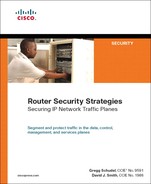
As previously mentioned, recoloring is the term used to describe the process of changing the precedence setting in the IP header of packets as they ingress your network. The IP header Precedence field (see Appendix B, Figure B-1) is used to indicate the level of importance for the packet. The defined values and their meanings are listed in Table 7-1.
Table 7-1. IP Header Precedence Field Settings
As an example, most routing protocols set their own traffic with a precedence value of 6—Internetwork Control. Cisco IOS uses this precedence value for some internal functions as well, such as Selective Packet Discard (SPD), to prioritize these packets within the IOS process-level queues that feed the route processor, as described in Chapter 5. Many QoS deployments take advantage of precedence marking as well. Some Internet sites have been known to purposely set their traffic with IP header Precedence values of 5, 6, or 7 in hopes that their content is provided higher-priority service. Attackers have also been known to set the precedence value in attack packets in hopes of giving their attack higher priority. The general guidance then is to reset (recolor) the IP header Precedence field to a value of 0 for all packets that ingress an external interface, or to whatever value is appropriate for your network and service. Example 7-1 uses MQC match access-group constructs. MQC accomplishes this by defining an ACL that describes the IP header Precedence values (Step 1), configuring a class-map to match on this ACL (Step 2), configuring a policy-map to recolor packets matching this class-map (Step 3), and then applying this policy to the desired interface on the ingress (input) direction using a service-policy (Step 4).
Example 7-1. MQC-Based Recoloring Implementation
! Step 1 - Create ACLs to match IP header Precedence (color)
access-list 160 permit ip any any precedence priority
access-list 160 permit ip any any precedence immediate
access-list 160 permit ip any any precedence flash
access-list 160 permit ip any any precedence flash-override
access-list 160 permit ip any any precedence critical
access-list 160 permit ip any any precedence internet
access-list 160 permit ip any any precedence network
!
! Step 2 - Create a class-map to match ACLs in Step 1
class-map match-color
match access-group 160
!
! Step 3 - Create a policy-map to apply policy (drop/drop)
policy-map re-color
class match-color
set ip precedence routine
!
! Step 4 - Apply service-policy to interface
interface pos1/1
encapsulation ppp
ip address 209.165.200.225 255.255.255.224
service-policy input re-color
!
Notice in Example 7-1 that access-list 160 only matches on IP header Precedence values of 1 through 7, but no explicit test is done for packets with a precedence value of 0. Because tests look for 1 through 7, which represents all other possible values, it is not necessary to test explicitly for 0 to ensure that all packets are being classified. Zero is the default value, and most packets should be set to this value. Of course, it is possible to define another ACL entry to match on 0 (routine), but strictly speaking it is not required. One reason to do so would be to provide statistics via ACL counters, as described next.
Tracking how packets are initially marked can be accomplished most easily by using the show access-list command to display the counters for ACL lines matching different precedence levels of incoming packets. Example 7-2 illustrates this concept.
Example 7-2. Monitoring Recoloring Access List Counters
router-a# show access-list 160
Extended IP access list 160
permit ip any any precedence priority (5637629 matches)
permit ip any any precedence immediate (3916144 matches)
permit ip any any precedence flash (1967437 matches)
permit ip any any precedence flash-override (4034766 matches)
permit ip any any precedence critical (2306059 matches)
permit ip any any precedence internet (8024235 matches)
permit ip any any precedence network (919538 matches)
Monitoring these values over time may give you some indication of impending attacks or even misconfigurations within the network. The use of EEM or custom scripts, as described in Chapter 6, “Management Plane Security,” can be used to provide this type of information.
Traffic Management Example
The following example illustrates the use of QoS and MQC in a traffic management role. In Example 7-3, traffic egressing the PE heading toward the CE is prioritized by IP precedence. This of course assumes that IP precedence values are properly set and can be trusted to reflect the nature of the traffic. In this case, several class-map statements are configured to match on IP precedence directly (no ACL is required), and a policy-map is used to allocate bandwidth via LLQ. LLQ allocates the assigned bandwidth to the priority queue, if configured, using the priority percent keyword. The remaining bandwidth is then allocated to each of the other configured traffic classes belonging to the policy map by using the bandwidth percent keyword. In this case, traffic matching precedence 5 is associated with the priority queue and given 35 percent of the bandwidth, perhaps to accommodate real-time voice traffic. Traffic matching precedence 4 and precedence 3 are given 25 percent and 15 percent of the bandwidth, respectively.
Example 7-3. QoS-Based Traffic Management Implementation
! Step 1 - Create class-map statements to classify traffic based on IP precedence
class-map match-any precedence3
match ip precedence 3
class-map match-any precedence4
match ip precedence 4
class-map match-any precedence5
match ip precedence 5
!
! Step 2 - Create policy-map to allocate bandwidth by class from Step 1
policy-map TrafficMgmt
class precedence5
priority percent 35
class precedence4
bandwidth percent 25
class precedence3
bandwidth percent 15
!
! Step 3 - Apply service-policy to interface
interface Serial1/0/0/2:0
description Circuit-123, Customer ABC-10
bandwidth 1536
ip vrf forwarding ABC
ip address 10.0.1.13 255.255.255.252
no ip directed-broadcast
no ip proxy-arp
no fair-queue
no cdp enable
service-policy output TrafficMgmt
!
Note
In Example 7-3, explicit class-map configurations are only used to match IP precedence 3, 4, and 5 because these classes have explicit bandwidth assignments. The remainder of the traffic (IP precedence values 0, 1, 2, 6, and 7) is handled within the class-default traffic class, which is implicitly defined and controlled. Additional details on this behavior are covered in the Cisco Press book QoS for IP/MPLS Networks (listed in the “Further Reading” section).
The show policy-map command is the primary tool for verifying the operation and configuration of QoS policies within MQC. The output of this command displays counters and rates for the configured actions on each class-map within the policy-map, as well as the always-defined class-default policy. The clear counters command resets all interface counters, including MQC counters, which is useful when comparative measurements are required for troubleshooting or traffic analysis. Example 7-4 illustrates the output of the show policy-map command for the policy defined in Example 7-3. There are no debug commands, however, because the MQC mechanisms are applied in the CEF fast path and the performance impact of debugging would be too great.
Example 7-4. Sample Output from the show policy-map Command
router-a# show policy-map interface Serial 0/0
Serial0/0
Service-policy output: TrafficMgmt
Class-map: precedence5 (match-any)
0 packets, 0 bytes
5 minute offered rate 0 bps, drop rate 0 bps
Match: ip precedence 5
0 packets, 0 bytes
5 minute rate 0 bps
Queueing
Strict Priority
Output Queue: Conversation 264
Bandwidth 35 (%)
Bandwidth 540 (kbps) Burst 13500 (Bytes)
(pkts matched/bytes matched) 0/0
(total drops/bytes drops) 0/0
Class-map: precedence4 (match-any)
0 packets, 0 bytes
5 minute offered rate 0 bps, drop rate 0 bps
Match: ip precedence 4
0 packets, 0 bytes
5 minute rate 0 bps
Queueing
Output Queue: Conversation 265
Bandwidth 25 (%)
Bandwidth 386 (kbps) Max Threshold 64 (packets)
(pkts matched/bytes matched) 0/0
(depth/total drops/no-buffer drops) 0/0/0
Class-map: precedence3 (match-any)
0 packets, 0 bytes
5 minute offered rate 0 bps, drop rate 0 bps
Match: ip precedence 3
0 packets, 0 bytes
5 minute rate 0 bps
Queueing
Output Queue: Conversation 266
Bandwidth 15 (%)
Bandwidth 231 (kbps) Max Threshold 64 (packets)
(pkts matched/bytes matched) 0/0
(depth/total drops/no-buffer drops) 0/0/0
Class-map: class-default (match-any)
3 packets, 72 bytes
5 minute offered rate 0 bps, drop rate 0 bps
Match: any
router-a#
Now that the basic mechanisms of MQC and QoS have been described, it is possible to discuss the main aspects of QoS services plane security.
Securing QoS Services
To deploy QoS and, implicitly, to secure the QoS service, you must take several considerations into account:
• You must expend the engineering effort to adequately define the traffic classes that make up your differentiated services architecture. Ensure that all packets entering or exiting the system can be classified, and that appropriate QoS policies can be applied to each class of traffic. No traffic should be unclassified and uncontrolled. This requires a complete understanding of the network topology, and the traffic flows within this topology.
• You must be able to accurately identify all points in the network where traffic classification can be accomplished. All traffic crossing defined points in the network (for example, the ingress link, egress link, and tunnel interface) must be classified and in many cases marked so that QoS mechanisms can be applied to the traffic either at that point or elsewhere within the network. QoS mechanisms (rates and percentages) assume that all traffic is accounted for. Thus, all traffic should be properly classified and marked because exceptions can disrupt these QoS mechanisms. This high-value service should be protected from theft or abuse by purposeful (malicious) mismarking. Therefore, you must deploy positive classification and marking schemes across all traffic types and boundaries to account for all traffic. From an IP traffic plane security perspective, where the QoS components are deployed is important. In theory, any network element can provide QoS services, assuming the platform is capable of implementing the appropriate mechanisms and performing the required actions. However, as highlighted in prior chapters, there are specific points in the network where implementing certain services makes more sense. In the case of DiffServ QoS, this is primarily (but not exclusively) at the edge of the network, and often in both the ingress and egress directions. External interfaces offer the most logical implementation point for ingress classification and marking. As described in Chapter 3, using the network edge as a reference point allows certain assumptions to be made about ingress packets that cannot be made elsewhere in the network. Recoloring at the edge enables you to perform other QoS and security functions deeper within the network by signaling QoS classification information that indicates the origin of the packets.
• You must be able to apply policies (actions) on all traffic to accomplish the desired goals of the QoS service without impacting overall network operations. If this is a new service, you must ensure that the hardware is capable of adequately supporting the deployment of the service without undue stress. Older platforms may be incapable of deploying certain QoS features at line rate, or may experience a significant increase in CPU utilization, for example. When this is the case, this alone opens a potential vulnerability by exposing other traffic planes, most notably the control plane, to stress potential instability. The deployment of QoS services cannot jeopardize the operations of the network. This can be assured through the use of appropriately scaled hardware and by allowing only applicable traffic to use the higher-priority QoS services. For the Cisco 12000, for example, legacy Engine 0–based line cards not only have limited MQC and QoS support (minimal match support, no marking support, and limited congestion management support), but they also suffer a significant performance degradation of approximately 50 percent when QoS is enabled. Modern Cisco 12000 line cards, such as those based on Engine 3 and Engine 5 (ISE) technologies, are designed as edge services cards and therefore support ingress and egress QoS and MQC (and other services) at line rate. Most CPU-based IOS devices, on the other hand, experience some performance degradation when QoS is enabled, although all MQC functions should be supported. For example, Cisco ISR routers may experience a 10 percent increase in CPU utilization with QoS functions enabled. Designers must also budget for QoS performance impacts and alternate solutions if routers are already stressed (high CPU). When deploying QoS, you should always consult the hardware release notes for your specific platforms to ensure that you understand the implications that enabling these features may have on system performance. In addition, it is always useful to perform laboratory tests under conditions simulating your production environment (including attack conditions) if feasible.
• You should apply defense in depth and breadth principles such as transit ACLs and uRPF to prevent unauthorized traffic from impacting the QoS service. DoS attacks are always more difficult to deal with when they target features that require special processing or that add extra processor burdens.
The preceding list represents recommendations based on generalized QoS and MQC deployments. Obviously, it is not possible to cover every scenario and situation in this chapter. Many other recommendations that are specific to topology and QoS service deployment should be considered based on your particular environment. It is the intention of these discussions and guidelines that you be able to recognize within your specific deployment scheme where potential vulnerabilities exist and how QoS must be protected. For more information on available QoS techniques to mitigate attacks within the IP data plane, see to Chapter 4.
MPLS VPN Services
Multiprotocol Label Switching (MPLS) Virtual Private Networks (VPN) provide traffic isolation and differentiation to create virtual networks across a shared IP network infrastructure. MPLS-based Layer 3 VPNs combine Multiprotocol BGP (M-BGP) using extended community attributes and VPN address families, LDP (RFC 3036) or RSVP-TE (RFC 3209) for label distribution, and router support for Virtual Routing and Forwarding (VRF) instances to create these virtual IP networks. These operate based on the Internet Engineering Task Force (IETF) RFC 4364 specification (which obsoletes RFC 2547bis).
An extensive discussion of the threats to MPLS VPNs was covered in Chapter 2, “Threat Models for IP Networks.” The purpose of this section is to review techniques available to protect MPLS VPN services from the threats described in Chapter 2. This section is not intended to provide detailed MPLS VPN design and implementation guidelines. A short overview of some of the components used in creating MPLS VPNs and some of the more common deployment aspects are covered in review, however. Some level of understanding of MPLS VPN arechitectures and their operational concepts is assumed. For additional information on deploying and securing MPLS VPNs, refer to the Cisco Press book entitled MPLS VPN Security (listed in the “Further Reading” section), which provides details on their architecture, deployment models, and security.
MPLS VPN Overview
As described in previous chapters, MPLS VPNs provide a site-to-site IP VPN service and are rapidly replacing legacy Frame Relay and ATM networks. SPs offer MPLS VPN services across a shared IP infrastructure. The SP IP network not only is shared among MPLS VPN customers but it may also be shared by SP customers of other services, including, for example, Internet transit, IPv6 VPNs (otherwise known as 6VPE), and Layer 2 VPNs (or pseudowires). Although the SP IP network is shared, addressing and routing separation, as well as privacy, are assured between customer VPNs, and between VPNs and the SP global IP routing table. This is inherently achieved through the use of the following mechanisms, as defined by RFC 4364 and as were described in Chapter 2:
• VPN-IPv4 addressing, to ensure unique addressing and routing separation between VPNs
• VRFs, to associate VPNs to physical (or logical) interfaces on provider edge (PE) routers
• Multiprotocol BGP (M-BGP), to exchange VPN routing information between PE routers
RFC 4364 also categorizes the different roles of IP routers within the MPLS VPN architecture, including customer edge (CE), provider edge (PE), provider core (P), and autonomous system boundary routers (ASBR), also described in Chapter 2 and illustrated in Figure 2-15. Unlike an Internet service, an MPLS VPN service is considered trusted; hence, often few or no security measures are applied. The following sections review techniques available to protect each of these different MPLS VPN router types (or categories) from the threats outlined in Chapter 2.
Customer Edge Security
Given the IP addressing and routing separation provided by MPLS VPNs, the CE router is reachable only from within its assigned VPN. Therefore, by default, the CE router is only susceptible to attacks sourced from inside the VPN. Only if the VPN has Internet or extranet connectivity configured (excluding the secure Management VPN per Chapter 6) is it susceptible to external attacks, as was described in Chapter 2. Keep in mind that the CE router is an IP router and is not enabled for any MPLS functionality (with the exception of the Carrier Supporting Carrier [CsC] model, which is described in the “Inter-Provider Edge Security” section later in the chapter). Hence, to mitigate the risk of attacks against the CE router, the data, control, and management plane security techniques described in Chapters 4 through 6 may be applied, including:
• Data plane security
— Interface ACLs
— Unicast RPF
— Flexible Packet Matching (FPM)
— QoS
— IP Options handling techniques
— ICMP data plane techniques
— Disabling IP directed broadcasts
— IP transport and application layer techniques
• Control plane security
— Disabling unnecessary services
— ICMP control plane techniques
— Selective Packet Discard
— IP Receive ACLs (rACLs)
— Control Plane Policing (CoPP)
— Neighbor authentication (MD-5)
— Protocol specific ACL filters
— BGP security techniques (GTSM, prefix filtering, etc.)
• Management plane security
— SNMP techniques
— Disabling unused management plane services
— Disabling idle user sessions
— System banners
— AutoSecure
— SSH
— AAA/TACACS+/RADIUS
— Syslog
— NTP
— NetFlow
— Management VPN (specifically designed for managed MPLS VPN CE routers)
The preceding techniques would be deployed in the same manner as was described in Chapters 4 through 6; hence, they will not be repeated here.
Note
Note, however, the CE router is deployed within a private IP (MPLS) VPN versus being reachable from the wider Internet. Therefore, you may consider deploying only those security techniques that mitigate the risk of significant threats. Spoofing attacks, for example, may not be considered a significant threat within MPLS VPNs. The optimal techniques that provide an effective security solution will vary by organization and depend on network topology, product mix, traffic behavior, operational complexity and organizational mission.
Provider Edge Security
As described in Chapter 2, PE routers associate physical (or logical) interfaces to customer VPNs using VRFs. VRFs are statically assigned to interfaces and cannot be modified without PE router reconfiguration. Using a static VRF configuration provides complete separation between VPNs, and between VPNs and the SP global IP routing table. VPN customer packets cannot travel outside of the assigned VPN unless the SP VPN policies specifically allow for it. Conversely, external packets cannot be injected inside the VPN unless specifically allowed by policy. That is, only a misconfiguration or software vulnerability would allow illegal unauthorized packets to leak into or out of a customer VPN.
Although the PE provides routing and addressing separation between VPNs, it is also IP reachable within each configured VPN. This makes it susceptible to internal IP attacks sourced from within a VPN. Internal attacks sourced from within a private VPN may be considered low risk. However, given that a PE router aggregates many customers and VPNs, an attack against the PE from within one VPN may adversely affect other VPN customers because the PE router shares its resources, including CPU, memory, and (uplink) interface bandwidth, among the different customer VPNs. Hence, although an MPLS VPN assures routing and addressing separation between VPNs and between VPNs and the global IP routing table, collateral damage remains a valid threat.
The PE router appears as a native IP router to VPN customers (excluding CsC customers, as described in the “Inter-Provider Edge Security” section later in the chapter). A single VPN customer site generally has IP reachability to all of the PEs configured for the associated customer VPN. Hence, to mitigate the risk of VPN customer attacks against PE routers, many of the data, control, and management plane security techniques described in Chapters 4 through 6 may be applied. Note, all of these techniques are generally supported for MPLS VPNs and VRF interfaces; however, specific platform restrictions may apply. Further, these techniques would be generally deployed in the same manner as was described in Chapters 4 through 6 and so their application will not be repeated here. However, some additional considerations for MPLS VPN PE routers are described in the following list, including resource management per VPN to limit the risk of collateral damage.
Infrastructure ACL
VPN customers and CE routers require minimal, if any, protocol access to the PE routers. Most MPLS VPN deployments only require dynamic routing (for example, eBGP or EIGRP) between the PE and the directly connected CE. Infrastructure ACLs are specifically designed to prevent IP packets from reaching destination addresses that make up the SP core network, including the PE external interface addresses themselves. Thus, iACLs may be applied on the PE router, inbound on each CE-facing interface to filter all traffic destined to the PE except routing protocol traffic from the directly connected CE router. This type of policy may be applied on the PE, on each CE-facing interface. Note that if the iACLs filter traffic from the directly connected CE router only and not from CE routers associated with other sites within the VPN, additional protection steps may be required. To protect PEs from remote attacks sourced from other sites within the VPN, you could simply not carry the IP prefixes associated with the PE-CE links within the VRF routing table. Or, if CE reachability is required in support of VoIP gateway, firewall, or IPsec services, for example, you may use any one of the three techniques outlined in the “Edge Router External Link Protection” section of Chapter 4. If static routing is used on the PE-CE link, the infrastructure ACL should simply deny all traffic destined to the PE external interfaces. IP rACLs and/or CoPP should also be applied as a second layer of defense in the event that the infrastructure ACL and external link protection policies are bypassed. IP rACLs and CoPP in the context of MPLS VPNs are discussed next.
IP Receive ACL
As described in Chapter 5, IP rACL policies apply to all CEF receive adjacency traffic. However, IP rACLs are not VRF-aware, and thus polices applied on PE routers are unable to distinguish between receive adjacency traffic that is associated with each customer VRF or the global table when filtering solely based upon IP source addresses. Given that the PE supports a distinct VRF table for each customer VPN, and that each customer VPN, as well as the PE itself, may use overlapping IP addressing, this leaves open the possibility for ambiguities within IP rACL policies and potentially allows unauthorized traffic to incorrectly be permitted by the IP rACL. For example, if the IP rACL policy permits all BGP traffic from the 209.165.200.224/27 subnet, then traffic sourced from any 209.165.200.224/27 address within any VPN configured on the PE, or any traffic sourced from an 209.165.200.224/27 address within the global table will be permitted by the IP rACL. This situation can be resolved by also configuring infrastructure ACLs as needed, to fully rationalize each traffic source. It should be noted that IP rACL filtering based upon IP destination address information is not exposed to the same issues because any permitted destination address must be that of a CEF receive adjacency.
Control Plane Policing
CoPP policies that use IP source address information will suffer from the same issues just described for IP rACLs. That is, CoPP is not VRF-aware at this time, and thus does not consider the ingress VRF. This is conceivably less of an issue for CoPP than for IP rACLs in that CoPP typically is provisioned to rate limit traffic types to infrastructure destination IP addresses.
VRF Prefix Limits
Although BGP neighbor prefix limits may be applied as described in Chapter 4 per BGP peer, you may also configure a maximum prefix limit for each VRF table defined within the PE routers. This allows you to limit the maximum number of routes in a VRF table to prevent a PE router from importing too many routes. The VPN prefix limit is protocol independent as well as independent of the number of CE peers or sites within a VPN. To enable this feature, use the maximum routes <limit> {warn-threshold | warn-only} command in IOS VRF configuration mode. This allows you to monitor and limit PE routing table resources used per VPN/VRF. You can use the maximum routes command to monitor and limit the number of routes in a VRF on a PE router. By default, IOS does not limit the maximum number of prefixes per VRF table. You may specify a limit by using the maximum routes command. Routes are rejected when a maximum number as set by the limit argument is reached. A percentage of this maximum number of permitted routes can also be defined by specifying the warn-threshold argument. When configured, IOS generates a Syslog warning message every time a route is added to a VRF when the VRF route count is above the warning threshold. IOS also generates a route rejection Syslog notification when the maximum threshold limit is reached and every time a route is rejected after the limit is reached. To generate a warning message only instead of a imposing a hard VRF prefix limit, use the warn-only keyword within the maximum routes command.
IP Fragmentation and Reassembly
As described in Chapter 2, MPLS VPN PE routers impose an 8-byte MPLS shim for all unicast traffic received from connected CE routers and destined to remote VPN sites across the MPLS core. The addition of the 8-byte MPLS shim may result in IP fragmentation of customer VPN traffic. If IP fragmentation occurs, a flood of VPN traffic may adversely affect the ingress PE router because this traffic must be handled in the slow path. For unicast VPN traffic, any PE fragmented IP packets will be reassembled by the destination address specified within the customer VPN packets. Hence, only the ingress PE router is affected. Conversely, for multicast VPN (MVPN) traffic (which is encapsulated within a 24-byte GRE point-to-multipoint tunnel header and not an MPLS header, per IETF draft-rosen-vpn-mcast-08.txt), the egress PE may be required to reassemble the fragmented MVPN (GRE) packets because the GRE tunnel endpoint (or destination address) is the egress PE itself.
As outlined in Chapter 2, IP routers have a limited number of IP fragment reassembly buffers. Further, fragment reassembly is handled at the IOS process level. If PE routers are required to fragment VPN traffic and/or reassemble fragmented MVPN traffic, they are potentially susceptible to DoS attacks crafted with large packets. Given the different tunnel header encapsulations used for unicast and MVPN traffic (in other words, 8 versus 24 bytes), avoiding unicast fragmentation does not necessarily mitigate the risk associated with MVPN fragmentation and reassembly. Multicast fragmentation must be considered if MVPN services are offered. Additionally, it is also possible for large packets to be used for an ICMP attack. In this scenario, the attacker simply sets the Don’t Fragment (DF) bit of the oversized packets. If the PE router cannot fragment the packet due to the DF bit being set, it sends an ICMP Packet Too Big message back to the source. An excessive volume of these crafted packets can trigger a DoS condition on the router.
The only technique available to mitigate the risks associated with IP fragmentation and reassembly is to engineer the network to simply avoid it. This may be achieved only by ensuring that the MPLS core network from ingress PE to egress PE supports an MTU greater than that of all IP access and aggregation networks (in other words, PE-CE links) and must be large enough to accommodate the additional MPLS and/or GRE encapsulations imposed. In this way, any VPN packets received at the edge are guaranteed not to be fragmented when transiting the core. Further, the MTU setting should be universal across the network edge. Otherwise, fragmentation may occur depending upon the entry or exit points at the network edge.
When fragmentation cannot be eliminated through network design, every effort must be made to mitigate the impacts of any fragmentation and reassembly that may still occur. There are a number of strategies for resolving fragmentation within the context of MPLS VPNs, and the best approach depends on your particular environment and on how much work you are willing to do to prevent fragmentation. There is no panacea, however, and some engineering effort must be expended to determine the best approach.
To avoid fragmentation (and possibly reassembly) on the PEs, the MPLS core network must support an MTU greater than that of the PE-CE links. The best-case scenario, then, is to set the egress interface MTU value of every CE router to a suitable value that guarantees there will be no fragmentation within the MPLS core. For example, assume that the interface MTU is 1500 bytes everywhere within the MPLS core network. The CE egress interface MTU must be reduced, then, by an amount equal to or greater than the maximum combination of tunnel headers imposed across the MPLS core. This includes either the 8-byte label stack imposed for unicast VPN traffic or the 24-byte GRE header imposed for MVPN traffic. If other encapsulations are also used within MPLS core, their overhead must be accommodated as well. For example, MPLS TE tunnels between MPLS core P routers can also influence the maximum packet size to avoid fragmentation. In the preceding example, because all interfaces have an MTU of 1500 bytes, all unicast traffic greater than 1492 bytes would be fragmented by the ingress PE. Similarly, all MVPN traffic greater than 1476 bytes would be fragmented at the ingress PE and then require reassembly at the egress PE.
The main approaches to modifying the interface MTU of the CE links include the following:
• Modify the Interface Layer 2 MTU: By making modifications to the CE egress interface Layer 2 MTU, fragmentation may be avoided on the PE. The interface command mtu <value> is used to set the maximum transmission unit (MTU)—that is the maximum packet size for outbound packets at Layer 2. Thus, any Layer 3 protocols will be subjected to this value (for example, IP). The IOS default MTU setting depends on the interface medium. Table 7-2 lists IOS default MTU values according to media type.
Table 7-2. Cisco IOS Default MTU Values

• Modify the Interface Layer 3 (IP) MTU: To modify the CE egress interface Layer 3 MTU value, use the ip mtu <value> interface configuration command. Note that the Layer 3 interface MTU is protocol-specific. Namely, this Layer 3 interface MTU command applies only to IP packets, whereas the Layer 2 interface MTU command applies to any upper-layer protocols that are transmitted on the interface. With the proper interface or IP MTU setting on the CE, the CE will then perform the IP fragmentation when necessary, and not the ingress PE.
When the CE router is not managed by the SP, the SP cannot rely on each of its customers to set the MTU accordingly on the CE router. Hence, instead of reducing the MTU on the CE router, ideally the SP should increase the MTU within the core of their network to accommodate the maximum PE-CE MTU size plus sufficient overhead for any possible MPLS label stack. Given wide deployment of POS interfaces within MPLS VPN core networks as well as Gigabit Ethernet interfaces enabled for jumbo frames, MTUs of 4470 bytes or 9000 bytes, respectively, are commonly supported. This allows SPs to eliminate the likelihood of fragmentation and reassembly within their MPLS core, assuming the MTU of the PE-CE link is 1500 bytes.
Note
Changing default MTU settings may cause the router to recarve system packet buffers to accommodate the new MTU applied. This may disrupt packet-forwarding operations during the period of time it takes to complete the buffer recarve operations.
Provider Core Security
Excluding the PE router, the SP infrastructure is inherently hidden from MPLS VPN customers, given VPN routing separation. Consequently, it is not possible for a VPN customer to launch direct attacks against core (P) routers due to the absence of IP reachability. Further, MPLS core (P) routers do not carry VPN customer prefixes, hence, the IP rACL, CoPP and VRF prefix limits issues outlined for PE routers do not apply to core (P) routers. Nevertheless, core (P) routers remain susceptible to transit attacks, as described in Chapter 2. Hence, to mitigate the risk of attacks from VPN customers against the core (P) routers, the following techniques may be applied.
Disable IP TTL to MPLS TTL Propagation at the Network Edge
By default, when IP packets are MPLS encapsulated, the IP TTL is copied down into the TTL fields of the imposed MPLS labels. Not only does this allow VPN customer packets to expire within the MPLS core network, but it also provides VPN customers with visibility of the core network using IP traceroute. Both of these conditions represent potential security risks. RFC 3032 and IETF draft-ietf-mpls-icmp-07 specify the interaction between MPLS and ICMP, and allow for ICMP messages generated by the core (P) routers to be sent to a source host within a customer VPN as required, including ICMP Time Exceeded (Type 11) messages. To mitigate the risk of VPN customer packets expiring on core (P) routers, the no mpls ip propagate-ttl forwarded command must be applied on all PE and ASBR routers within IOS global configuration mode. This command disables the propagation of the IP TTL into the MPLS label stack. Instead, the MPLS TTL values are set to 255 (the maximum available value per RFC 3032), preventing VPN customer packets from expiring within the MPLS core network (unless of course a routing loop exists, in which case TTL expiration is desired). Note that disabling IP TTL to MPLS TTL propagation in this way does not break VPN customer IP traceroute. It simply prevents the core (P) routers from being reported when the VPN customer performs IP traceroute. The VPN customer will see only the CE routers and ingress PE router, and not the core (P) routers. In this way, the MPLS core network remains hidden and appears as a single hop. The egress PE router is optionally reported depending upon the MPLS tunneling model applied per RFC 3443. As stated, the no mpls ip propagate-ttl forwarded command must be applied on all edge routers (PEs and ASBRs), because this is where the MPLS encapsulation of VPN customer packets takes place. Further, disabling IP TTL to MPLS TTL propagation does not affect the SP’s ability to use IP traceroute across the internal infrastructure either. For more information on TTL processing in MPLS networks, refer to RFC 3443.
IP Fragmentation
Similar to the description in the previous section for PE routers without proper MTU support across the MPLS core, P routers are also susceptible to fragmentation and/or ICMP attacks resulting from large packets. Excessive fragmentation may trigger a DoS condition in core (P) routers. This can be mitigated with a proper Layer 2 or Layer 3 interface MTU setting at the network edge, as described for PE security techniques in the Provider Edge Security section above, or by ensuring that the MTU within the core of the network is sufficiently large to accommodate the maximum PE-CE MTU size plus sufficient overhead for any possible MPLS label stack.
Router Alert Label
As described in Chapters 2 and 4, VPN customer traffic both with and without IP header options is always MPLS-encapsulated at the ingress PE and forwarded downstream across the MPLS core. There are exceptions, however. VPN packets with IP Source Route options will be MPLS label switched only if the IP addresses specified in the Source Route option are valid addresses within the associated VRF. If not, these packets will be discarded. Once MPLS-encapsulated, however, core (P) routers forward packets based upon the MPLS label stack and do not consider the IP header options of VPN customer packets (because it is beneath the labels and not seen by core (P) routers). RFC 3032 defines an MPLS Router Alert Label, which is analogous to the IP header Router Alert option. When applied, MPLS packets tagged with the Router Alert Label will be punted to the IOS process-level for packet handling. At the time of this writing, there is no industry or IETF standard for IP header option processing in MPLS networks to specify when the MPLS Router Alert Label should (or should not) be imposed. Consequently, each MPLS VPN PE router platform may potentially behave differently in this regard. MPLS PE router platforms that impose the Router Alert Label (at the top of the label stack) may make downstream core (P) routers susceptible to security attacks, given that such packets will be handled at the IOS process level. A sustained attack that sends crafted IP packets having the IP header Router Alert option, for example, to an MPLS VPN PE that imposes the MPLS Router Alert label may trigger a DoS condition within the MPLS core. At the time of this writing, Cisco IOS MPLS VPN PE routers do not impose the MPLS Router Alert label for VPN customer packets. But, again, because there is no industry standard, non-IOS MPLS VPN PE routers may behave differently. If your MPLS VPN PE router imposes the Router Alert label for VPN packets which have an IP header Router Alert option, you should consider filtering these packets at the PE to mitigate the risk they present to the core. Techniques to filter IP options packets on IOS routers are described in Chapter 4.
Network SLAs
Similar to IP TTL handling described at the beginning of this list, when IP packets are MPLS encapsulated, the IP precedence value, by default, is copied down into the EXP fields of the imposed MPLS labels. Hence, without proper QoS policies at the PE, VPN customers may craft their low-priority traffic as high-priority in an attempt to either steal high-priority MPLS core bandwidth from other high-priority services or to launch attacks against high-priority traffic classes, including control plane protocols. Both of these scenarios assume that a DiffServ QoS architecture is implemented within the MPLS core. To mitigate this risk, packet recoloring and policing should be applied uniformly across the network edge, as described in the “Securing QoS Services” section above, and earlier in Chapter 4.
The preceding techniques outline specific steps you may take to protect core P routers in the context of MPLS VPN–based attacks. Only a PE router misconfiguration or software vulnerability would provide IP reachability between a VPN customer and the MPLS core (P) routers. Further, if the SP network also provides other services such as Internet transit, the core P routers may be susceptible to other threats, as described in Chapter 2. Hence, you should also consider deploying the applicable data, control, and management plane security techniques described in Chapters 4 through 6 to mitigate the risks associated with these other threats. Note that IOS also supports MD5 authentication for MPLS LDP, which is the most widely deployed label distribution protocol for MPLS VPN services. Chapter 9, “Service Provider Network Case Study,” illustrates the combination of techniques and defense in depth and breadth principles that SPs should consider to protect their infrastructure and services, including MPLS VPNs.
Inter-Provider Edge Security
As described in Chapter 2, there are two primary components of the inter-provider MPLS VPN architecture: Carrier Supporting Carrier (CsC) and Inter-AS VPNs. CsC is a hierarchical VPN model that enables downstream service providers (DSP), or customer carriers, to interconnect geographically diverse IP or MPLS networks over an MPLS VPN backbone. This eliminates the need for customer carriers to build and maintain their own private IP or MPLS backbone.
Inter-AS is a peer-to-peer model that enables customer VPNs to be extended through multiple SP or multi-domain networks. Using Inter-AS VPN techniques, SPs peer with one another and offer end-to-end VPN connectivity over extended geographical locations for those VPN customers who may be out of reach for a single SP. Both CsC and Inter-AS VPNs maintain segmentation between distinct customer VPNs.
Carrier Supporting Carrier Security
From a security perspective, the CsC-PE router is subject to the same threats as the native MPLS VPN PE router. Similarly, the CsC-CE router is subject to the same threats as the native MPLS VPN CE router. Further, because the customer carrier is itself an SP, the CsC-CE is also a core (P) router from the perspective of DSP customers. The potential threats against the CsC-CE as a customer carrier core router depend upon whether the DSP offers Internet transit or MPLS VPN services, or both. Each of these types of threats were detailed in Chapter 2.
The primary difference from a security perspective between native MPLS VPNs and the CsC model is that data plane packets exchanged between the CsC-CE and CsC-PE routers are MPLS encapsulated. This makes some IP data plane security techniques such as IP ACLs ineffective (as described in the list below). Again, however, this only applies to MPLS labeled data plane packets not native IP packets. Despite the use of MPLS labeled data plane packets, the CsC-CE router is reachable only from within the associated customer carrier VPN and is not susceptible to external attacks through the CsC provider. This is strictly enforced at the CsC-PE through an automatic MPLS label spoofing avoidance mechanism that prevents the CsC-CE from using spoofed MPLS labels to transmit unauthorized packets into another customer VPN. MPLS packets with spoofed labels are automatically discarded upon ingress of the CsC-PE. This is possible because, within IOS, the labels distributed from the CsC-PE to the CsC-CE using either LDP or RFC 3107 (BGP plus labels) are VRF-aware. Hence, CsC provides addressing and routing separation between VPNs equivalent to native MPLS VPNs. Therefore, the security techniques outlined above in the “Customer Edge Security,” “Provider Edge Security,” and “Provider Core Security” sections also apply to CsC services. Additionally, the following security considerations also apply to CsC services:
• Interface IP ACLs: Interface ACLs are IP-based and hence do not apply to MPLS labeled packets. Although IP ACLs may be ineffective against MPLS labeled data plane packets, unlabeled control plane traffic between the CsC-CE and CsC-PE may be filtered using infrastructure IP ACLs.
• CoPP: Similar to IP ACLs outlined directly above, labeled data plane exception traffic such as MPLS packets with the Router Alert Label are always classified into the class-default traffic class of a CoPP policy. This is because (at the time of this writing) MPLS packets are considered Layer 2 and will not match any IP ACL MQC match criteria configured within the CoPP policy.
• IP TTL propagation: The no mpls ip propagate-ttl forwarded command (outlined earlier in the “Provider Core Security” section) which was used to protect the MPLS core (P) routers from TTL expiry attacks, does not apply to CsC-PE routers (or PE interfaces enabled for CsC). This command only applies to ingress IP packets being encapsulated into MPLS. It does not apply to ingress MPLS packets being MPLS label switched because no IP TTL to MPLS TTL propagation operation is performed. Given that the CsC-PE (or PE interface enabled for CsC) receives MPLS labeled packets from the CsC-CE, this command does not apply to CsC services. Hence, in the CsC model, unless this command is applied upstream in the CsC customer’s network, it is possible for CsC customer packets to TTL-expire within the MPLS core of the SP providing the CsC service (in other words, between the ingress and egress CsC-PEs).
• Label distribution: Label distribution between the CsC-CE and CsC-PE may be done using either MPLS LDP or BGP (RFC 3107). Using only BGP, the control plane between the CsC-CE and CsC-PE routers operates similarly to native MPLS VPNs and the different BGP security techniques reviewed in Chapter 5 may be applied. Conversely, MPLS LDP supports MD5 authentication as well as inbound and outbound filtering of label advertisements. Each of these MPLS LDP security techniques were also described in Chapter 5.
Inter-AS VPN Security
Inter-AS VPNs are intended to expand the reach of customer VPNs through multiple SP networks. This is meant to overcome issues where the primary SP footprint may not match the required footprint of the VPN customer, most notably in multinational deployments. RFC 4364 Section 10 outlines three techniques to achieve this, which are widely known within the industry as options (a), (b), and (c). Each has trade-offs in terms of scalability, security, and service awareness. Chapter 2 presented the security threats associated with each option under the condition that the interconnect between each distinct MPLS VPN network is under the control of different SPs (that is, is untrusted). The security of each Inter-AS VPN option is briefly described here:
• Option (a): Within option (a), the ASBR router of each SP network effectively operates as a PE router. Further, each ASBR sees its peer ASBR as a CE router. Hence, all of the security techniques previously outlined for native MPLS VPN PE routers apply equally to ASBR routers configured for Inter-AS VPN option (a). As such, this is the only Inter-AS VPN interconnect model that provides for resource management on a per-VPN basis. That is, option (a) maintains separate data plane and control plane instances per VPN (for example, VRF prefix limits, eBGP peering, IP interface per VRF, and so on), unlike options (b) and (c). For this reason, option (a) is the only IOS Inter-AS VPN interconnect model known at the time of this writing to be deployed in production between two (2) distinct SPs. This technique is illustrated in Figure 2-17.
• Option (b): Within option (b), the ASBR routers use a single Multiprotocol eBGP session to exchange all Inter-AS VPN customer prefixes over a single native IP (non-VRF) interface between SPs. Although this improves ASBR scaling since only a single interconnect and eBGP session required, it prevents ASBR resource management and security policies on a per-VPN basis. That is, all of the per-VPN techniques such as VRF prefix limits, eBGP peering, IP interface per VRF, and so forth, cannot be applied because option (b) carries all Inter-AS VPNs using a shared interconnect and eBGP peering session for each SP peer. In fact, an option (b) ASBR does not need to be configured with any VRF instances. Because there is no VPN isolation, option (b) Inter-AS VPNs share a common fate whereby one Inter-AS VPN may adversely impact connectivity of another, given the shared data and control plane within the ASBR. Also, because no VRF interface configurations are applied on the ASBR, MPLS label spoofing avoidance checks similar to CsC cannot be enforced on the interconnect, which may allow unauthorized access to a customer VPN. Further, the data plane security techniques described in Chapter 4 do not apply to MPLS label switched packets. Hence, Inter-AS VPN option (b) is susceptible to a variety of security risks that cannot be properly mitigated. Because of these weaknesses, option (b) is not known at the time of this writing to be deployed in production between two 2) distinct SPs for Inter-AS VPN connectivity using IOS. Conversely, for multi-domain (or multi-AS) SP networks, option (b) may be considered since the different domains are managed by the same single SP. (This technique is illustrated in Figure 2-18.)
• Option (c): Within option (c), the ASBR routers exchange only PE /32 loopback addresses and associated label information using either MPLS LDP or BGP + Labels (RFC 3107). VPN customer prefixes are then exchanged between route reflectors (RRs) within each SP network (AS) using multihop Multiprotocol-eBGP. (This technique is illustrated in Figure 2-19.) Because this option requires external IP reachability between each SPs (internal) M-BGP route reflector (RR), not only are the RRs exposed to attack, but the MPLS core network of each SP is also now exposed. Similar to option (b), there is no way to verify the integrity of the MPLS label stack, making VPN label spoofing possible. Hence, Inter-AS VPN option (c) also suffers from a variety of security risks, and at the time of this writing, is not known to be deployed in production using IOS because this model is deemed insecure for Inter-AS VPN connectivity between different SPs. Conversely, for multi-domain (or multi-AS) SP networks, option (c) may be considered since the different domains are managed by the same single SP.
The preceding guidelines are based on generalized MPLS VPN deployments. Obviously, it is not possible to cover every MPLS VPN deployment scenario in this chapter. Many other topology and service -specific considerations may apply. This section provided you with general guidelines for enhancing the security of MPLS VPN services. Additional MPLS VPN security topics and details are provided in the Cisco Press book entitled MPLS VPN Security, which is listed in the “Further Reading” section.
Although MPLS VPNs provide addressing and routing separation between customer VPNs similar to FR and ATM VPNs, they do not provide cryptographic privacy. The next section reviews IP services plane deployments involving IPsec VPNs.
IPsec VPN Services
The IP Security (IPsec) protocol suite encompasses a set of RFC standards, including RFC 2401 and related standards RFC 2402 through 2412 and 2451, which provide mechanisms for securing Layer 3 IP communications. Although IPsec standards apply to both IPv4 and IPv6 environments, only IPv4 is discussed here. IPsec can be deployed by itself, generally for corporate network extensions over public networks, although it is frequently combined with other services such as GRE or MPLS VPNs as a means of adding security layers to these other services. For example, many companies are now implementing IPsec within their MPLS VPN networks as a means of providing confidentiality (data privacy) along with the segmentation provided by MPLS VPNs. IPsec VPNs, by themselves, provide limited support for things such as dynamic routing, multicast, and so on, which other services such as GRE and MPLS VPNs provide. Hence, the combination of these services often provides the most operationally sound deployment environment.
An extensive discussion of the major threats to IPsec VPNs was already covered in Chapter 2. The purpose of this section is to take these areas where IPsec VPN services are most vulnerable to attack and to describe how to protect these services. This section is not intended to provide detailed IPsec VPN design and implementation guidelines. A short overview of some of the components used in creating IPsec VPNs and some of the more common deployment aspects are covered in review, however. Some level of understanding of IPsec VPNs and their operational concepts, architecture, design, and deployment options is assumed. For additional information on deploying and securing IPsec VPNs, refer to the Cisco Press book IPSec VPN Design (listed in the “Further Reading” section), which provides details on their architecture, deployment models, and security.
IPsec VPN Overview
As introduced in Chapter 2, IPsec VPNs are used to provide confidentiality, authentication, and integrity to IP traffic. To provide these features, IPsec VPNs use a two-part system, not unlike other VPN technologies, where a control channel component is first established to manage the IPsec VPN attributes, and then a separate data channel provides the secure mechanisms for transmitting the actual data stream. In IPsec VPNs, the control channel is provided by the Internet Key Exchange (IKE) protocol, and the data protection is provided by one or both of two IPsec protocols know as the Encapsulating Security Payload (ESP) protocol and the Authentication Header (AH) protocol. Each of these components is described briefly next.
IKE
IKE functions as the control channel for IPsec VPNs. In this role, IKE actually performs two separate functions. The first, known as IKE Phase 1, provides VPN endpoint authentication and establishes the method by which IKE will protect itself (encryption and hashing algorithms). To do this, IKE establishes a single, bidirectional security association (SA) for itself, and then brings up the control channel using this SA. It is through this control channel that IKE manages subsequent connections on behalf of IPsec. The second function, known as IKE Phase 2, is the actual IPsec session management function in which IKE negotiates how IPsec connections should be protected, and builds the set of SAs, one for each direction of the IPsec connection. SAs for IPsec are unidirectional and specific to ESP or AH, so there will be at least two SAs per IPsec connection and possibly four if both ESP and AH are invoked. IKE Phase 2 then manages these IPsec connections (negotiates setup, teardown, key refresh, and so on).
Figure 7-2 illustrates these concepts, showing the single IKE control channel (bidirectional) and two IPsec (unidirectional) data channels (one in each direction). Note that IKE Phase 2 is also where the ESP and AH protocols negotiate such parameters as encryption, hashing algorithms, keys, and values for timers and keepalives.
Figure 7-2. IPsec Control Channel (IKE SA) and Data Channel (IPsec SAs)

Diffie Hellman (DH) is a cryptographic key exchange protocol that allows two parties that have no prior knowledge of each other to jointly establish a shared secret key over an insecure communications channel. DH is the basic mechanism of the Oakley key exchange protocol that is used in the IKE process for deriving the shared secret keys between two IPsec parties that are subsequently used for the data encryption process. IKE uses the DH mechanisms both during Phase 1 in the establishment of its own bi-direction (control channel) SA, as well as during Phase 2 in the establishment of both unidirectional (data plane) IPsec SAs.
IKE control channel sessions can be established using one of two modes: main mode or aggressive mode. Main mode is normally used for site-to-site VPN connections, whereas aggressive mode is normally used for remote-access VPN client session establishment. The primary difference between the two modes is in the number of messages they use to exchange endpoint attributes. Main mode uses more messages, and certain endpoint information exchange is delayed until they can be exchanged securely. Aggressive mode attempts to complete IKE session establishment within a minimum number of packets, albeit via a less secure packet exchange. This being the case, main mode consumes more processing and resources before knowing whether a session request is legitimate or not (in other words, before completing or deleting the IKE session), and thus is more susceptible to resource exhaustion attacks. This issue, which occurs in the original version of IKE (IKEv1), is corrected in IKEv2. Also, it is worth noting that IKE uses UDP as transport, defaulting to port 500, but typically using UDP port 4500 when NAT transparency mode is used.
After IKE has established its control plane, IPsec can be brought up for the actual data exchange portion of the VPN. User data can be encrypted, authenticated, or both, using the IPsec protocols ESP or AH (individually or both) to process and encapsulate user data. Each of these two IPsec protocols has its own IP protocol number, 50 and 51 respectively. These protocols are briefly described in the next section.
IPsec
As just stated, IPsec provides two protocols to define how the data will be processed within the VPN—the Encapsulating Security Protocol (ESP), and the Authentication Header (AH) protocol. These two protocols are described as follows:
• Encapsulating Security Payload (ESP): ESP is identified by IP protocol number 50 and is the protocol that handles encryption of IP data at Layer 3 to provide data confidentiality. It uses symmetric-key cryptographic algorithms, including NULL, Data Encryption Standard (DES), Triple DES (3DES), and Advanced Encryption Standard (AES), to encrypt the payload of each IP packet. When IPsec builds packets using the ESP protocol, an ESP header is either inserted between the original IP packet header and payload (for example, Layer 4 header + data) in transport mode or prefixed to the original IP header and full payload along with a new IP header in tunnel mode. These two modes of operation for ESP are described in more detail shortly. ESP by itself also provides some authentication and integrity capabilities, albeit with slightly less scope of coverage over each IP packet than what AH provides. As such, ESP can be used to provide encryption only, encryption plus authentication, or authentication only. (ESP can be used to provide similar services to AH using NULL encryption. The difference from ESP with authentication only is that AH also authenticates parts of the outer IP header—for instance, source and destination addresses—making certain that the packet really came from whom the IP header claims it is from.)
• Authentication Header (AH): AH is identified by the IP protocol number 51, and provides authentication and integrity services used to verify that a packet has not been altered or tampered with during transmission. The Authentication Header is either inserted between the original IP packet header and payload (for example, TCP header + data) in transport mode or prefixed to the original IP header and full payload along with a new IP header in tunnel mode. These two modes of operation for AH are described in more detail shortly. AH can be used in combination with ESP if privacy and full authenticity and integrity are required, or it can be used by itself to guarantee only the authenticity and integrity (not privacy) of each IP packet. When used in conjunction with digital certificates, the use of AH also provides non-repudiation functions for received packets. AH authenticates all parts of the IP packet, including the data, and all parts of the IP header.
Through the use of these protocols, the set of security services offered by IPsec includes access control, connectionless integrity, data origin authentication, protection against replay, confidentiality (encryption), and limited traffic flow confidentiality (tunnel mode only).
As noted, the tunnels shown in Figure 7-2 are represented by SAs stored on each device. SAs are an important part of the IPsec process because they define the trust relationships negotiated between any two IPsec endpoints. Through SAs, end devices agree on the security policies that will be used and identify the SA by an IP address, a security protocol identifier, and a unique security parameter index (SPI) value.
IPsec may be operated in one of two modes:
• Transport mode: IPsec transport mode retains the original IP header of the transported datagram. It can be used to secure a connection from a VPN client directly to the security gateway, for example, for IPsec protected remote configuration. Transport mode is generally used to support direct host-to-host communications. Transport mode for ESP or AH encapsulates the upper-layer payload, above the IP layer. These are typical Layer 4 and higher payloads such as TCP, UDP, and so on. This leaves the original Layer 3 IP header intact, allowing it to be used for other network services, such as the application of QoS. AH transport mode would be used for applications that need to maintain the original IP header and just need authentication and data integrity services. ESP transport mode would be used for applications that need to maintain the original IP header but also want to encrypt the remainder of the packet payload. Examples of the ESP and AH IPsec header additions for transport mode are shown in Figure 7-3(a) and Figure 7-4(a), respectively.
Figure 7-3. Application of IPsec ESP to IP Datagrams in Tunnel Mode and Transport Mode

Figure 7-4. Application of IPsec AH to IP Datagrams in Tunnel Mode and Transport Mode
• Tunnel mode: IPsec tunnel mode completely encapsulates and protects the contents of an entire IP packet, including the original IP header. Tunnel mode indicates that the traffic will be tunneled to a remote gateway, which will decrypt/authenticate the data, extract it from its tunnel, and pass it on to its final destination. When using tunnel mode, an eavesdropper would see all traffic as sourced from and destined to the IPsec VPN tunnel endpoints, and not the true source and destination endpoints of the established data session. IPsec tunnel mode adds a new, 20-byte outer IP header to each packet, in addition to a minimum of 36 bytes for ESP or 24 bytes for AH as required for other packet header and trailer parameters applied by each protocol. When IPsec tunnel mode is combined with GRE, an additional 24 bytes is added by the GRE shim and GRE tunnel IP header. Examples of the ESP and AH IPsec header additions for tunnel mode are shown in Figure 7-3(b) and Figure 7-4(b), respectively.
IPsec is designed per IETF standards for IP unicast-based traffic only. As such, when there are requirements to apply IPsec to multicast applications, non-IP traffic, or routing protocols that use multicast or broadcast addressing, then the additional use of a generic route encapsulation (GRE) tunneling is necessary. GRE provides the means for encapsulating many traffic types within unicast IP packets, hence meeting the requirement for IPsec encapsulation. With IPsec and GRE working together, support is available for multicast applications; routing protocols such as Open Shortest Path First (OSPF), Routing Information Protocol (RIP), and Enhanced Interior Gateway Routing Protocol (EIGRP); or even the transport of non-IP traffic such as IPX or AppleTalk within an IPsec environment.
A simple example configuration of an IPsec VPN using ESP encapsulation in tunnel mode is illustrated in Figure 7-5, with the corresponding configuration being given in Example 7-5. Figure 7-6 and corresponding configuration Example 7-6 show the same topology again for the comparable IPsec plus GRE architecture as a direct comparison.
Figure 7-5. IPsec VPN Deployment Using ESP Tunnel Mode

Figure 7-6. IPsec + GRE VPN Deployment Using ESP Tunnel Mode
Example 7-5. IPsec VPN Configuration Using ESP Tunnel Mode
Router-A Configuration
!
crypto isakmp policy 10
authentication pre-share
crypto isakmp key cisco123 address 192.168.5.1
!
crypto ipsec transform-set VPN-trans esp-3des esp-md5-hmac
!
crypto map vpnmap local-address Serial0//0
crypto map vpnmap 10 ipsec-isakmp
set peer 192.168.5.1
set transform-set VPN-trans
match address 101
!
interface Ethernet1
ip address 10.1.1.1 255.255.255.0
interface Serial1/0
ip address 192.168.1.1 255.255.255.252
crypto map vpnmap
!
access-list 101 permit ip 10.1.1.0 0.0.0.255 10.1.2.0 0.0.0.255
!
ip route 0.0.0.0 0.0.0.0 192.168.1.2
Router-B Configuration
!
crypto isakmp policy 10
authentication pre-share
crypto isakmp key cisco123 address 192.168.1.1
!
crypto ipsectransform-set VPN-trans esp-3des esp-md5-hmac
!
crypto map vpnmap local-address Serial0//0
crypto map vpnmap 10 ipsec-isakmp
set peer 192.168.1.1
set transform-set VPN-trans
match address 101
!
interface Ethernet1
ip address 10.1.2.1 255.255.255.0
interface Serial1/0
ip address 192.168.5.1 255.255.255.252
crypto map vpnmap
!
access-list 101 permit ip 10.1.2.0 0.0.0.255 10.1.1.0 0.0.0.255
!
ip route 0.0.0.0 0.0.0.0 192.168.5.2
The example illustrated in Figure 7-5 and the corresponding configurations in Example 7-5 draw on many default conditions and represent a very basic IPsec VPN setup in Cisco IOS. For brevity, only the relevant configuration components are shown. This example is useful nonetheless for illustrating the details of IPsec VPNs.
The components of relevance include the crypto isakmp configuration, which provisions the IKE Phase 1 process, and the crypto ipsec transform-set configuration, which provisions the IKE Phase 2 process. The crypto map elements tie the Phase 1 and Phase 2 components together, and the use of an access-list (101 in Example 7-5) specifies which traffic should be subjected to the IPsec VPN process.
It should be noted that the Phase 1 and Phase 2 attributes match in both router configurations, and that the access list entries in ACL 101 are reciprocals (mirror images) of each other. These are requirements for Cisco IPsec VPN configurations. Note also the use of the default route (ip route) as well. In this case, all traffic is forwarded toward the same next hop. However, only the traffic matching the crypto ACL will be encrypted and sent across the IPsec VPN tunnel. The remaining traffic (that which does not match the crypto ACL) is forwarded unaltered. In one sense, you may think of this as being similar to a static routing decision, because the router encrypts and encapsulates packets matching this ACL and forwards them not based on the original destination IP address, but instead based on the IPsec header destination IP address (in other words, the set peer address). For Cisco IOS, it is important to note that each entry in the crypto ACL causes the creation of a unique pair of SAs because these ACL entries represent IPsec policy enforcement specifications. SA creation and maintenance consumes resources on the router, and thus a finite number can be allocated.
Similar to the way in which managing static routes becomes overwhelming as your network size increase (and thus the benefit of the use of dynamic routing protocols), IPsec VPNs often enlist the aid of the GRE tunneling mechanisms to enable the use of dynamic routing protocols for similar efficiencies. Managing crypto ACL entries can become overwhelming and resource-consuming as IPsec VPN networks increase in size. One way to minimize the creation of SAs and at the same time obtain the benefits of dynamic routing is to use GRE tunneling within IPsec VPNs. IPsec (by IETF standards) is only capable of carrying unicast IP packets. Because GRE is itself a unicast IP packet, it is possible to apply the IPsec VPN policy to GRE-encapsulated traffic. This not only greatly simplifies the crypto ACL construction, as illustrated in Example 7-6, but also allows for the use of a dynamic routing protocol (across the GRE tunnel). The example illustrated in Figure 7-6 and the corresponding configurations in Example 7-6 show a very simplified IPsec plus GRE VPN deployment.
Example 7-6. IPsec + GRE VPN Configuration Using ESP Tunnel Mode
Router-A Configuration
crypto isakmp policy 10
authentication pre-share
crypto isakmp key cisco123 address 192.168.5.1
!
crypto ipsec transform-set VPN-trans esp-3des esp-md5-hmac
!
crypto map vpnmap local-address Serial0//0
crypto map vpnmap 10 ipsec-isakmp
set peer 192.168.5.1
set transform-set VPN-trans
match address 102
!
interface Ethernet1
ip address 10.1.1.1 255.255.255.0
interface Serial1/0
ip address 192.168.1.1 255.255.255.252
interface Tunnel0
ip address 10.10.255.1 255.255.255.252
ip mtu 1400
tunnel source Serial0/0
tunnel destination 192.168.5.1
crypto map vpnmap
!
router eigrp 100
network 10.0.0.0 0.0.0.255
no auto-summary
!
ip route 0.0.0.0 0.0.0.0 192.168.1.2
!
access-list 102 permit gre host 192.168.1.1 host 192.168.5.1
Router-B Configuration
crypto isakmp policy 10
authentication pre-share
crypto isakmp key cisco123 address 192.168.1.1
!
crypto ipsectransform-set VPN-trans esp-3des esp-md5-hmac
!
crypto map vpnmap local-address Serial0//0
crypto map vpnmap 10 ipsec-isakmp
set peer 192.168.1.1
set transform-set VPN-trans
match address 102
!
interface Ethernet1
ip address 10.1.2.1 255.255.255.0
interface Serial1/0
ip address 192.168.5.1 255.255.255.252
interface Tunnel0
ip address 10.10.255.2 255.255.255.252
ip mtu 1400
tunnel source Serial0/0
tunnel destination 192.168.1.1
crypto map vpnmap
!
router eigrp 100
network 10.0.0.0 0.0.0.255
no auto-summary
!
ip route 0.0.0.0 0.0.0.0 192.168.5.2
!
access-list 102 permit gre host 192.168.5.1 host 192.168.1.1
Because the topologies in Figure 7-5 and Figure 7-6 include only two endpoints, the efficiency gains in using GRE are perhaps not obvious from the configurations in Example 7-5 and Example 7-6. It should be apparent, however, that as more networks are added behind the IPsec gateways (Routers A and B), additional entries in the crypto ACL would be required in Example 7-5 (and as a result, more SAs would be built). The crypto ACL in Example 7-6, on the other hand, would remain unchanged because it only refers to the GRE tunnel endpoints in the crypto ACLs, and dynamic routing takes care of the rest.
The preceding examples are very basic and are intended solely to illustrate the service components required for IPsec VPNs for the purpose of providing a point of reference for the security recommendations described next. There are many excellent references that deal specifically with IPsec VPN architectures and their optimizations. Some of these are referenced in the Further Reading section at the end of this chapter.
Securing IPsec VPN Services
It may sound odd that a security protocol such as IPsec requires protection itself. However, when considering that implementing IPsec requires significant additional packet processing resources above and beyond normal data plane forwarding, not to mention the establishment and maintenance of a separate control plane, it is easy to see why the IPsec process itself must be protected. Additional CPU processing (mainly for IKE functions), memory consumption (for SA storage), and specialized hardware (for encryption) are used to implement IPsec VPNs. The two main reasons for protecting IPsec include the following:
• IPsec is a complex service: IPsec involves extra packet handling, the maintenance of state, and additional interconnected complexities with routing, NAT, and other processing functions. Thus, IPsec can itself become a potential DoS target. Whether malicious or unintentional through misconfigurations and inadvertent resource consumption, it is possible to impact the IPsec service itself, or even the platform(s) upon which the service is hosted.
• IPsec is a specialized service: IPsec is a specialized service that requires additional resources beyond normal forwarding. Although newer hardware options are available to increase the capacity and performance of IPsec VPNs, these still remain premium services. Because this hardware represents a finite resource, only selected packets should be capable of using the service. In addition, the encryption process itself can add delay in forwarding, so QoS mechanisms may also need to be applied to prioritize flows within the IPsec VPN.
The main ideas here are essentially the same as with the other services previously described. The services plane applies additional packet handling requirements, implying that they can become DoS targets. In addition, services represent scarce resources (as compared with standard data plane forwarding), implying that the service should be reserved for selected packets. Thus, the following considerations should be made when deploying IPsec VPNs.
IKE Security
As described above in the IPsec VPN Overview section, the IKE establishes and maintains the control plane for IPsec VPNs. IKE uses UDP as transport, defaulting to port 500. IKE packets are receive packets and are normally processed by the router CPU itself. Because the IKE process must be publicly reachable, it is exposed to direct attack. In addition, the first version of IKE (IKEv1), the most generally deployed version today, requires that some fairly significant amount of processing be accomplished within the IKE Phase 1 negotiation process before it can determine whether the IKE request is legitimate or not. (IKEv2 provides some corrective measures to help alleviate this issue.) Thus, you should take steps to protect the IKE process. The following approaches can be taken, and may be layered with other mechanisms for additional protection:
• Interface ACLs: Interface ACLs may be used to limit the sources permitted to reach the IKE process if specific source IP addresses are known. This mainly applies for site-to-site VPNs with fixed IP addresses, because remote-access VPNs generally are sourced from unknown addresses. In the case where this is acceptable, the access list entries should permit selected traffic to reach UDP port 500. (Infrastructure ACL construction and deployment for control plane protection is covered in Chapter 5.)
• CoPP: Because IKE packets are receive packets that are processed by the router CPU, they are seen by CoPP mechanisms. CoPP can be used to rate limit IKE connection requests to the router. This has proven effective in cases where the source of the IKE requests is not previously known. Keep in mind that both legitimate and malicious requests will be rate limited. (Specific details on CoPP construction and deployment for control plane processes are covered in Chapter 5.)
• Call Admission Control: In later versions of Cisco IOS, a feature named Call Admission Control (CAC) was introduced to protect processes such as IKE session establishment. CAC may be configured and applied to IKE in one of two ways:
— To limit the number of IKE SAs that a router can establish, you may configure an absolute IKE SA limit by entering the crypto call admission limit ike sa command in IOS global configuration mode. In this case, the router drops new IKE SA requests when the configured value has been reached.
— To limit the system resources that the router may dedicate to IKE, expressed as a percentage of maximum global system resources available, you may configure the call admission limit command, also in IOS global configuration mode. In this case, the router drops new IKE SA requests when the specified percentage of system resources being used exceeds the configured value.
More information on CAC may be found in the Cisco.com “Call Admission Control for IKE” reference in the “Further Reading” section.
Fragmentation
Fragmentation occurs when the IP packet size exceeds the egress link MTU. In modern networks, this is normally not an issue for standard IP forwarding, but, just as in the case of MPLS section above, when services plane protocols such as IPsec encapsulate packets, the added overhead results in oversized IP packets that may require fragmentation before transmission. IP packet fragmentation is never desirable. As previously described in Chapter 2, fragmentation requires slow path processing and results in performance impacts. This performance impact manifests itself in several ways, some of which are generic to fragmentation in general, and some of which are specific to IPsec in particular. The following discusses both types of issues and then describes options for avoiding or managing fragmentation:
• General fragmentation issues: Generally, fragmentation requires the support of slow path processing on routers. Because of this, there is a performance impact simply due to slow path forwarding when fragmentation is required. In addition, fragmentation involves splitting one packet into two, and if the original packet is only slightly oversized, these two new packets will include one large packet and one small packet. Because there are now twice as many packets to forward, and when looking at the maximum forwarding rate of the platform on a PPS basis, you have now consumed twice the resources (headers, trailers, inter-packet delays, routing decisions, and so on) for the same amount of data. In addition, all intermediate routers must forward these additional packets as well. Finally, the receiver must reassemble the fragments, and if any fragments are lost along the way, the entire packet must be retransmitted.
• IPsec specific fragmentation issues: More specifically for IPsec, fragmentation can have an even more significant impact on router performance. One thing that should be obvious from Figures 7-3 and 7-4 is that the original packet size increases by up to 84 bytes, depending on IPsec options and mode. By default, packets are fragmented after encryption. When that happens, it causes reassembly to be required by the IPsec VPN peer router prior to decryption. Routers are not designed for fragmentation reassembly, and reassembly is even more processor intensive than fragmentation. For IPsec VPNs, two interrupts are required: one to get packets to the reassembly process, and one to get packets to the decryption process. (Reassembly is not normally required to be performed by the router for normal data plane traffic because the destination address is the end host, not the router itself.) When fragmentation and reassembly must be done in support of IPsec, this can reduce the forwarding performance by as much as 70 percent. As described in Chapter 2, IP routers have a limited number of reassembly buffers, which may also limit the rate of packet retransmissions. Finally, as mentioned above in the previous bullet point, fragmentation often results in the generation of two packets—one large and one small. This intermingling of large and small packets can result in very uneven delays in encryption processing and serialization and may have significant impacts on latency and jitter-sensitive applications deployed across the IPsec VPN.
Of course, the best scenario is to avoid fragmentation altogether. When applications are sending small data packets, fragmentation is never an issue. However, when large packets are involved, fragmentation consequences must be considered. There are a number of strategies for resolving fragmentation within the context of IPsec VPNs, and the best approach depends on your particular environment and on how much work you are willing to do to prevent fragmentation. There is no panacea, however, and some engineering effort must be expended to determine the best approach. The main approaches for preventing or managing fragmentation follow. The main idea for all of these techniques is to avoid both fragmentation and reassembly if possible. When this is not possible, minimize its impact on network performance by using these techniques.
Host MSS Modification
Hosts participating in IPsec VPNs can be hard coded to transmit IP packets that will not exceed a specified size. This technique completely eliminates fragmentation for all packet types. Many IPsec remote-access clients, including the Cisco client for example, provide options for setting this value on the host. (Typically, a value of 1400 bytes is used.) For hosts behind IPsec gateways, manual configuration of this value can be accomplished as well. More information on setting this value on common operating systems may be found in the Cisco Tech Note “Adjusting IP MTU, TCP MSS, and PMTUD on Windows and Sun Systems,” referenced in the “Further Reading” section. You should also review your host operating system guide for specific details on setting this value. Note, however, that you cannot trust a compromised host to send properly sized packets that will not require fragmentation and reassembly.
Path MTU Discovery (PMTUD)
PMTUD (RFC 1191) was designed to dynamically determine the lowest MTU between two endpoints. There are several inherent requirements for PMTUD to work successfully, and when it works correctly, it can eliminate fragmentation for certain packet types. First, from the originating end host perspective, PMTUD only works for TCP sessions. Second, PMTUD requires that originating packets be transmitted by the host with the IP header DF bit set to 1 (enabled). This causes these packets to be dropped along the path by any forwarding device that is unable to forward the packet when fragmentation is required. In such a case, when the packet is dropped, an ICMP Type 3, Code 4 message (Fragmentation Needed and DF Was Set) is sent from the device that cannot forward the packet due to fragmentation requirements, to the originating IP address. This ICMP Type 3 Code 4 message also contains the required MTU setting necessary for successful transmission. (See Appendix B for more details on this ICMP message type.) In this way, the end host can dynamically learn the correct MTU and reduce packet size automatically to accommodate IPsec overhead.
IPsec participates in PMTUD conversations by default (per RFC 2401) and no extra configuration is required. When GRE is used in conjunction with IPsec, PMTUD must be enabled for the GRE tunnel as well by using the tunnel path-mtu-discovery command within the interface configuration mode. Any firewalls or ACLs along the return path that block ICMP packets will cause PMTUD to fail. PMTUD includes timers that age out the dynamically learned MTU value (the default is 10 minutes). This causes the PMTUD process to be repeated periodically. Finally, from the end host perspective, TCP is the only protocol that participates in PMTUD. Hence, if other protocols are used—say, for example, you are “testing” your links with large ICMP Echo Request packets and setting the DF bit—they will fail to be transmitted. (Other options must be pursued for non-TCP applications.)
Interface TCP MSS Modification
The TCP protocol Maximum Segment Size (MSS) (or Maximum Send Segment as it is sometimes referred to) option is sent by hosts within the TCP SYN packet during the TCP connection establishment phase. Each TCP end host then obey the MSS value conveyed by the other end. When IP traffic involves the TCP protocol, Cisco IOS CLI provides a mechanism (per interface) to intercept TCP SYN packets and insert a specific MSS value. The relevant interface command is ip tcp adjust-mss <size>, where size represents the maximum TCP segment size (in bytes) and must account for the header lengths (in bytes) for IP (20), TCP (20), GRE (24), and IPsec (up to 60) header components, meaning the value for <size> could be as small as 1376 bytes. This command should be configured on ingress interfaces toward the private side (originating hosts), or on the GRE tunnel interface. Obviously, this configuration option applies only to TCP traffic, but it can eliminate fragmentation issues when TCP protocols are involved.
Interface MTU Modification
As previously discussed in the MPLS VPN section above, the interface MTU may be set at either Layer 2 or Layer 3 to leave room in advance for IPsec overhead. To modify the Layer 2 interface MTU, use the mtu <value> interface configuration command. To modify the Layer 3 interface MTU value, use the ip mtu <value> interface configuration command. The Layer 3 form of this command may be used for GRE tunnels as well. The difference between the Layer 2 interface MTU and the Layer 3 interface MTU is that the Layer 3 interface MTU is protocol-specific. Namely, the ip mtu command only applies to IP packets, whereas the Layer 2 mtu command applies to any upper-layer protocols transmitted on the interface (for example, MPLS, L2TPv3, ARP, CDP, and so on). Using either of these techniques will have one of two effects on fragmentation:
• If PMTUD is enabled and host packets are TCP and originated with DF = 1, reducing the interface MTU will cause PMTUD to occur once (upon packet ingress to the router), which is not only much earlier in the processing, but also before the IPsec encryption occurs. This ensures that the receiving router will not be required to perform reassembly prior to decryption. If GRE is used, this configuration may save two PMTUD iterations (once prior to GRE encapsulation and a second after IPsec encryption.
• When PMTUD is not an option (DF = 0 or non-TCP protocol), modifying the interface MTU will at least cause fragmentation to occur prior to IPsec encryption (or GRE encapsulation), thereby saving precious resources on the tunnel receive end because reassembly is no longer required prior to IPsec decryption.
Note
Changing default MTU settings may cause the router recarving system packet buffers to accommodate the new MTU applied. This may disrupt packet-forwarding operations during the period of time it takes to complete the buffer recarve operations.
Look Ahead Fragmentation
When fragmentation absolutely cannot be avoided for whatever reason (for example, non-TCP, ICMP filtered, and so on), as a last resort the best option is to ensure that the DF bit is cleared so that all packets can at least be transmitted through the network (albeit with fragmentation being required). This can be accomplished within Cisco IOS using the crypto ipsec df-bit clear command, and then applying the crypto ipsec fragmentation before-encryption command (in either interface or global configuration mode). This feature, also known as look-ahead fragmentation, requires IPsec tunnel mode for support. Note that this Cisco IOS allows you to change the default (RFC specified) behavior of IPsec which is to fragment after encryption. This “looking ahead” feature causes IPsec to check the outbound interface MTU on a per-packet basis prior to encryption to predetermine if fragmentation will be required. If the packet will require fragmentation after IPsec encapsulation, IOS will fragment the packet prior to the encryption process. This saves precious resources on the tunnel receive end in that only decryption (as standard) is required and fragments can be forwarded downstream to the final destination for reassembly. This method does not prevent fragmentation, but does avoid reassembly at the tunnel receive end.
IPsec VPN Access Control
When you deploy an IPsec tunnel to encrypt data between private sites, it does not speak to the type of traffic being carried within the tunnel. For example, if an infected host on one side of the VPN attempts to infect hosts on the other side of the VPN, instead of having good traffic traversing your encrypted tunnel, you now have bad traffic traversing the tunnel. At a minimum, these precious IPsec VPN resources are being consumed by malicious traffic, which reduces their availability to legitimate traffic. This is not the only scenario where traffic flows must be considered. Thus, several IPsec VPN deployment techniques must be considered.
Crypto ACLs
Crypto ACLs (for example, ACL 101 in Example 7-5) define the IPsec SA proxy identities, and hence what traffic is to be encrypted (protected) by IPsec. You must use care when defining crypto ACLs, and consider them in conjunction with your routing tables. Just as over-summarizing routes can cause traffic black-holing, over-summarizing (or missummarizing) crypto ACL policies can cause unexpected behaviors, especially when default routes are used.
For example, consider the topology in Figure 7-5 and the configuration in Example 7-5. Note that default routes are used on both sides, and that crypto ACLs are specifically defined to include only the specific /24 owned by each router. If a packet is sourced from 10.1.1.1 behind Router-A and is destined to 10.1.2.1, it will be routed according to the default route, and then match the crypto ACL. Hence, it will be encrypted and sent across the IPsec tunnel as expected. But what if the destination was something other than 10.1.2.0/24? Say the destination is 10.10.2.1 or something that is not explicitly allocated by either endpoint. In this case, this packet would be routed by the default route, but fail the crypto ACL check. That is, it will be forwarded to the next hop (192.168.1.2 in this case) unaltered by IPsec. This may be what you intend, but if it is not, you must make accommodations to achieve the proper response. (It is not uncommon for SPs to receive many IP packets with private addresses due to errors like these.) It may be that a NAT policy should be implemented (also know as split tunneling), or it may be appropriate to drop such packets.
Considering Example 7-5 again, suppose the crypto ACL on each side was changed to access-list 101 permit ip 10.0.0.0 0.255.255.255 10.0.0.0 0.255.255.255. How would the packet forwarding behavior change? In this case, a packet sourced from 10.1.1.1 behind Router-A destined to 10.1.2.1 will be routed according to the default route, and then match the crypto ACL. Hence, it will be encrypted and sent across the IPsec tunnel and decrypted by Router-B as expected. But what about a packet sourced from 10.1.1.1 behind Router-A that is destined to some address that Router-B does not own, such as 10.10.2.1? In this case, the packet will be routed according to the default route, and then match the crypto ACL and be IPsec tunneled to Router-B, which will then decrypt the packet, perform a route lookup for the original destination (10.10.2.1 in this case), and route the packet via the default route back across the tunnel. This will continue until the packet TTL expires. Due to an imbalance between the routing table and the crypto ACL, a routing loop has been created. Packets from an infected host scanning for other vulnerable machines could generate this kind of traffic and would certainly consume all of the available encryption capacity. Host or server misconfigurations could also result in these kinds of packet loops and present the appearance of a DoS attack.
The main idea here is to ensure that your crypto ACLs are appropriately configured to account for the prefixes they can reach. Just as with routing, be careful not to oversummarize within crypto ACLs for addresses you do not own or have access to. Many administrators use GRE and dynamic routing protocols for this exact reason (as illustrated in Figure 7-6 and Example 7-6) because this type of configuration separates the crypto ACL policies from the routing policies and simplifies the overall IPsec configuration.
As illustrated in the case, when a default route is used, unintended behaviors can result. This is especially critical under attack scenarios. For example, worms often scan the entire network block associated with the host they infect. In the preceding scenario, this would mean the worm would scan the entire 10/8 network. Due to the default route, packets destined for prefixes in the 10/8 block and that are not covered by the crypto ACL will be forwarded toward the next hop. If NAT is employed, these bogus packets will consume all of the NAT resources. In this case, it is best practice to install a static route for 10/8 that points to Null0 (that is, ip route 10.0.0.0 255.0.0.0 Null0). This covers all networks that are not accounted for by more specific routes acquired through either static routes or dynamic routing protocols. These more specific routes will forward traffic to legitimate destinations, and the Null0 route will drop packets destined to bogus prefixes within your network block. The default route can still be used to provide access to the Internet for appropriate prefixes. This does not prevent bogus traffic from traversing the IPsec tunnel. However, it does protect the NAT process that would be used for split tunneling (to the Internet). End host security mechanisms should still be deployed, which are out of the scope of this book.
Interface ACLs
Interface ACLs may be used to apply stateless filtering on ingress interfaces toward the private side (originating hosts) to limit access to the IPsec process to only those packets and protocols that require IPsec encryption. This not only eliminates unnecessary packets from consuming precious encryption resources, but can make the task of defining crypto ACLs less complex. Remember that each crypto ACL entry results in the generation of two SA pairs. The SA database represents state in the router, which is a finite resource, and limiting the number of SAs that need to be created is prudent. In addition, during failover, IPsec will attempt to rebuild all failed SAs. Minimizing the number of SAs also improves high-availability performance.
CoPP
As noted earlier in the IKE section, IKE is a process on the router CPU and, hence, can be controlled by the CoPP mechanism. GRE also hits the router CPU and is also subject to CoPP mechanisms. Therefore, any policies applied to the control plane using CoPP must include specific entries for IKE and GRE when employed. (Specific details on CoPP construction and deployment are covered in Chapter 5.)
QoS
There are potentially two issues that may require the use of QoS with IPsec VPNs:
• Specialized hardware: IPsec services are often provided using specialized hardware or platforms. Typically, the performance of this hardware (in terms of PPS or bandwidth) is some fraction of the total bandwidth of the overall network itself. Thus, IPsec represents a finite resource that may be oversubscribed. Therefore, QoS is often deployed in conjunction with IPsec VPNs to prioritize traffic within the tunnel. Typically this is accomplished by configuring the QoS service policies on all IPsec VPN endpoints (gateways). By default, QoS functions occur within Cisco IOS after IPsec encryption on egress interfaces. (See the Cisco IOS feature order of operations illustration in Figure 7-1.) Because the entire original packet is encrypted when using IPsec VPNs, viewing the original IP header DSCP values or TOS bits would normally not be possible.
Cisco IOS provides the QoS pre-classify feature to allow both IPsec VPNs and QoS to occur on the same system. This feature preserves the DSCP/TOS bit setting of the original packet by copying this information to the IP header of the final IPsec VPN packet. This allows for normal QoS functions to operate on the outer IP header associated with the IPsec VPN tunnel. This feature is enabled via the qos pre-classify interface configuration command, which may be applied to physical interfaces and to tunnel interfaces.
• Encryption hardware and LLQ: Encryption hardware processes packets on a first-in, first-out (FIFO) basis, and when large packets precede small packets, delay and jitter for the small packets can vary significantly. This can happen, for example, when voice traffic and large data transfers are intermixed in IPsec VPNs without prioritization. Cisco IOS provides low latency queuing (LLQ) to IPsec encryption engines to help reduce packet latency. Instead of treating the input to the encryption processor as a single queue that gives equal status to all packets and results in FIFO processing, this LLQ capability designates two queues: a best-effort queue for data packets, and a priority queue for delay-sensitive packets. The encryption hardware processes packets in a manner that favors the priority queue and guarantees a minimum processing bandwidth. Additional information on LLQ and IPsec VPNs may be found in “Low Latency Queuing (LLQ) for IPSec Encryption Engines,” referenced in the “Further Reading” section.
Other IPsec Security-Related Features
There are many other security-related features applicable to highly available architectures, including resilient/redundant failover scenarios that also play a role in securing IPsec VPNs. These are outside the scope of this book. For more information, see the Cisco Press book IPSec VPN Design (see the “Further Reading” section), which covers many of these topics in detail.
Other Services
The preceding three IP services plane examples were selected for two primary reasons. First, they are widely deployed and, hence, you may already have familiarity with one if not all of them. In that case, hopefully the preceding discussions provided you an opportunity to review your own security deployments in support of these services (or encouraged you to do so). Second, they are useful for illustrating the thought process used to identify underlying weaknesses and attack vectors that exist within various services. Often times these challenges are obvious or direct, as is the case for IKE call admission for example, while other times they are not, as is the case for IPsec fragmentation impacts. Hopefully, the three examples above illustrate the common themes that must be well assessed when developing security methodologies for other services plane applications.
As indicated at the outset of this chapter, the services plane includes the application of processes that require additional packet handling above and beyond normal IP data plane forwarding processes. Within the context of this book, all services plane functions use at least the data plane. As in the case of MPLS and IPsec VPNs, these services also directly use the control plane. For QoS services, the control plane may also be used directly, as in the case of RSVP signaling. Although there is no way to completely generalize where or how all services are deployed, you will most likely find that these links and interdependencies between data plane and control plane components may provide attack vector opportunities within most services plane deployments.
Many other services are deployed within IP networks in addition to those covered by the three examples above. It is simply not possible to cover all possible services in detail within a single chapter, nor even a single book. However, a quick review and brief description of some of the more common services is appropriate and follows next.
SSL VPN Services
Secure Sockets Layer (SSL) VPNs are typically used to provide secure, clientless remote-access connectivity to corporate networks and assets. In contrast to IPsec, which was designed to provide secure services for IP packets (the network layer, Layer 3), SSL (and its successor, Transport Layer Security [TLS]) was designed to provide secure services for the transport layer (Layer 4). Officially, SSL can be used to add security to any protocol that uses reliable connections. However, SSL is predominantly associated with securing TCP-based applications, and within TCP, it is most commonly associated with securing web applications through the Secure Hypertext Transport Protocol (HTTPS, TCP port 443).
In contrast to IPsec, which requires the deployment and maintenance of a separate control plane through IKE for proper operations, SSL does not depend on a separate control plane to establish encrypted sessions between endpoints. Instead, all security negotiations are performed in-band between the server and client. Therefore, no separate control channel must be protected as is the case of IKE for IPsec. Similarly to IPsec, however, SSL can have a significant impact on the CPU levels of an SSL gateway when large numbers of session terminations occur due to the relatively high processing demands incurred by public-key cryptography. This implies that efforts must be taken to prevent precious CPU resources from being consumed, just as in the case of IPsec. In this regard, endpoint security cannot be ignored. One often-discussed disadvantage of SSL VPNs is that their universal access via web browsers allows connectivity from virtually anywhere, including untrusted locations and hosts (Internet cafes, kiosks, hotels, and so on), which poses significant risks for the corporate network.
For additional information on Cisco deployments of SSL VPNs, refer to the Cisco Press book Comparing, Designing, and Deploying VPNs, which provides details on architecture and deployments, or the Cisco.com article “SSL VPN Security,” both of which are listed in the “Further Reading” section.
VoIP Services
Voice over IP (VoIP) services carry voice signals over an IP network, and are one of the most compelling emerging technologies. VoIP services typically use standards-based protocols, including H.323, Session Initiation Protocol (SIP), or Media Gateway Control Protocol (MGCP). Officially called “Recommendation H.323,” H.323 refers to an umbrella recommendation from the International Telecommunication Union (ITU) for packet-based multimedia communications systems, including VoIP and IP-based videoconferencing (see the reference for H.323 in the “Further Reading” section). SIP is an application layer control protocol, defined in RFC 3261, and similarly, MGCP is defined by RFC 3435 (see the reference for these RFCs in the “Further Reading” section). All of these protocols use some combination of both TCP and UDP for transport, define fixed port numbers for a separate control channel used for call setup and management, and use dynamic port ranges for media streams. Real-time Transport Protocol (RTP) is used for audio streams. The main differences between these protocols primarily involve their call control architectures and call control signaling.
In many respects, VoIP services have similar design characteristics to IPsec VPN services, and thus many of the same security questions and solutions apply. For example, because VoIP services establish their own separate control channel to support call setup and call control, these control channels are subject to very similar security requirements as those created by IPsec VPNs.
VoIP services are also delay and jitter dependent, and are quite intolerant of packet loss. As such, QoS services are almost always deployed in conjunction with VoIP services, especially for business-class deployments. The deployment of security mechanisms and low-latency QoS techniques are often orthogonal, however, and security can negate the effectiveness of QoS in some cases. For example, RTP ports used for audio streams are usually dynamically assigned during call setup within the control channel. This complicates firewall deployments as they are now required to either permit a wide range of UDP ports access to the network, or have features to inspect the control channel to determine which ports to allow for each call. (Cisco firewalls perform this dynamic port tracking with a feature called fixups.)
Less-capable devices may add unacceptable latency in this inspection process, impacting the VoIP service quality. In addition, when encryption is used, QoS services may not be able to recognize and prioritize VoIP traffic from any other traffic. A session border controller (SBC) may also be used along with firewalls to exert control over the signaling involved in setting up and tearing down calls and the media streams.
Attacks directly against VoIP services are not necessarily required to break or disable the service entirely. Simply degrading the performance of the network may be sufficient to render the VoIP service unusable. VoIP relies upon a number of ancillary services as part of the configuration process and to deliver its services. These include but are not limited to DNS, DHCP, HTTP, HTTPS, SNMP, SSH, RSVP, and TFTP services. Securing the underlying infrastructure, as described in previous chapters, is requisite for securing VoIP services. DoS attacks against the network infrastructure (Layer 3 and Layer 2 attacks), against VoIP clients and servers, and against other essential but ancillary services (DNS, DHCP, TFTP, and so on) can all impact VoIP services.
Because VoIP protocols are still evolving, the features required to secure VoIP networks and services are still under development as well. For additional information on VoIP security based on Cisco SIP-enabled products, refer to the Cisco white paper “Security in SIP-Based Networks” and NIST Special Publication 800-58, Security Considerations for Voice Over IP Systems, both of which are listed in the “Further Reading” section.
Video Services
Video services are another one of the compelling emerging technologies, and are part of the new “triple play” of data, voice, and video offered by service providers. Video services share many common attributes with voice services and therefore share many of the same security concerns and solutions.
Like voice services, video services also require real-time delivery of data streams and are also dependent on delay and jitter (the variability in delay from one packet to the next). Video requires a constant bit stream to maintain the quality of the image. However, the single most important factor in the delivery of acceptable video services is the protection of the video stream from frame drops. When too many frames are lost, the video quality is impaired. Thus, network congestion must be avoided and so QoS is often applied as part of video services. Thus, the concerns previously described for VoIP and QoS apply here as well. Video services also establish their own separate control channel to support session setup and session control, and these control channels are subject to very similar security requirements as those described in the preceding section for voice services. DoS attacks against the control channel. Thus, attacks against video services, like attacks against voice services, may simply attempt to degrade the performance of the network, rendering the video service unusable.
Similar to voice services, video services may also be impacted by the deployment of security services. For example, the same dynamic port assignment issues described for voice services also apply for video services, and hence firewall deployments must be handled in a similar manner.
One potentially critical problem for video delivery that is not found in voice services is related to packet size. Whereas voice applications tend to require fairly small packets to transport audio streams, video applications (such as video conferencing, for example) can use large packet sizes. Video streams with typical MPEG-2 or MPEG-4 (Moving Pictures Experts Group) encoding and transported over RTP or other transport protocols can generate packets as large as the network MTU. From a security perspective, when video services are combined with VPN services such as MPLS or IPsec, there is the potential for IP fragmentation to be required due to the extra overhead involved in the VPN encapsulation process, as described in detail above in both the MPLS VPN and IPsec VPN sections. One of the main issues with fragmentation in the case of video is that each slightly oversized video packet is fragmented into one large and one small packet. This results in significant jitter through encryption engines and forwarding processes and causes significant impacts on the quality of video services. For dedicated video conferencing equipment, for example, the solution is simply to configure smaller maximum packet sizes to prevent fragmentation in the first place.
Video streams also may be carried in IP unicast or multicast packets, depending on the type of service (on-demand versus live broadcast, for example). In Chapters 2, you learned about several important issues related to securing IP multicast. Multicast can require a significant amount of packet punts within the control plane for state creation. Control signaling via Protocol Independent Multicast (PIM) or Internet Multicast Group Protocol (IGMP) must be protected, and control plane policing can be deployed for this purpose, as well as best practice techniques such as PIM neighbor filters and IGMP access groups. Similar techniques can be deployed for other multicast protocols as applicable.
Like voice services, video services also rely upon the same ancillary network support services as other applications, such as DNS, DHCP, HTTP, HTTPS, SNMP, SSH, RSVP, and TFTP services. Securing the underlying infrastructure, as described in previous chapters, is requisite for securing video services. DoS attacks against the network infrastructure (Layer 3 and Layer 2 attacks) and against other essential but ancillary services (DNS, DHCP, TFTP, and so on) can all impact video services.
Additional information on video services and security can be found in the Cisco Press book Voice and Video Conferencing Fundamentals, listed in the “Further Reading” section.
Summary
This chapter described security issues related to the IP services plane. The services plane refers to user traffic that requires specialized packet handling by network elements above and beyond the standard IP data plane forwarding process. Three IP services plane examples were described in detail; QoS, MPLS VPNs, and IPsec VPNs. The intention of describing these IP services plane examples was to illustrate the thought process used to identify underlying weaknesses and security threats that exist within these services. Hopefully, these examples illustrate the common themes that must be well understood when developing security methods for other services plane applications.
Within the context of this book, all services plane traffic uses at least the IP data plane and control plane of the network, but may also optionally establish a separate control plane session to support the underlying service. It is most often the case that interactions and interdependencies between data plane and control plane components are the most vulnerable areas in any services plane deployment. Also, many services depend on tight, or at least predictable, SLAs for operational deployments. In these cases, QoS impacts must be considered. In addition, it was shown that when VPN services are combined with other services, fragmentation can become problematic due to encapsulation overhead. In these cases, accommodations must be made to eliminate fragmentation. Finally, most services are highly dependent upon a number of ancillary services such as DNS, DHCP, HTTP, HTTPS, SNMP, SSH, RSVP, TFTP, and other baseline services, which all require protection. DoS attacks against the network infrastructure (Layer 3 and Layer 2 attacks) and against other ancillary but essential services (DNS, DHCP, TFTP, and so on) can impact nearly every IP service.
Review Questions
1 The services plane is distinguished from other IP traffic planes by what main attribute?
2 When deploying the DiffServ QoS model, what network edge technique should you deploy to prevent unauthorized use of high-priority traffic classes, and how is it implemented?
3 Name the three categories of MPLS VPN router types (excluding ASBRs) and identify the one that does not require MPLS functionality.
4 What, if any, are the challenges with IP rACL and CoPP policies applied on the PE router that use source address filtering?
5 How many bytes of transport overhead does an MPLS VPN ingress PE impose?
6 What is the IOS command to disable IP TTL to MPLS TTL propagation?
7 Which of the Inter-AS VPN architectural options is considered the most secure?
8 IPsec VPNs use IKE as a control plane. Briefly describe the functions provided by IKE, and indicate what protocol it uses for transport.
9 IPsec supports what two protocols, and what services do these two protocols provide?
10 IPsec VPNs may require fragmentation of IP packets. When fragmentation is of concern, name three options for preventing or minimizing fragmentation impacts.
Further Reading
Alvarez, S. QoS for IP/MPLS Networks. Cisco Press, 2006. ISBN: 1-58705-233-4.
Andreasen, F., and B. Foster. Media Gateway Control Protocol (MGCP) Version 1.0. RFC 3435. IETF, Jan. 2003. http://www.ietf.org/rfc/rfc3435.txt.
Behringer, M. H., and M. J. Morrow. MPLS VPN Security. Cisco Press, 2005. ISBN: 1-58705-183-4.
Bollapragada, V., M. Khalid, and S. Wainner. IPSec VPN Design. Cisco Press, March 2005. ISBN: 1-58705-111-7.
Evans, J. W., and C. Filsfils. Deploying IP and MPLS QoS for Multiservice Networks: Theory & Practice. Morgan Kaufmann, 2007. ISBN: 0-123-70549-5
Firestone, S., T. Ramalingam, and S. Fry. Voice and Video Conferencing Fundamentals. Cisco Press, 2007. ISBN: 1-58705-268-7.
Kuhn, D. R., T. J. Walsh, and S. Fries. Security Considerations for Voice Over IP Systems. NIST Special Publication 800-58. National Institute for Standards and Technology, January 2005. http://csrc.nist.gov/publications/nistpubs/800-58/SP800-58-final.pdf.
Lewis, M. Comparing, Designing, and Deploying VPNs. Cisco Press, 2006. ISBN: 1-58705-179-6.
Rosenberg, J. et al. SIP: Session Initiation Protocol. RFC 3261. IETF, June 2002. http://www.ietf.org/rfc/rfc3261.txt.
Song, S. “SSL VPN Security.” Cisco Documentation. http://www.cisco.com/web/about/security/intelligence/05_08_SSL-VPN-Security.html.
“Adjusting IP MTU, TCP MSS, and PMTUD on Windows and Sun Systems.” (Doc. ID: 13709.) Cisco Tech Note. http://www.cisco.com/warp/public/105/38.shtml.
“Call Admission Control for IKE.” Cisco IOS Software Releases 12.3T Feature Guide. http://www.cisco.com/en/US/products/sw/iosswrel/ps5207/products_feature_guide09186a0080229125.html.
“H.323: Packet-based Multimedia Communications Systems.” ITU Recommendation, June 2006. http://www.itu.int/rec/T-REC-H.323/en.
“Low Latency Queuing (LLQ) for IPSec Encryption Engines.” Cisco IOS Software Releases 12.2T Feature Guide. http://www.cisco.com/en/US/products/sw/iosswrel/ps1839/products_feature_guide09186a008013489a.html.
“Pre-Fragmentation for IPSec VPNs.” Cisco IOS Security Configuration Guide, Release 12.4. http://www.cisco.com/en/US/products/ps6350/products_configuration_guide_chapter09186a0080455b91.html.
“Resolve IP Fragmentation, MTU, MSS, and PMTUD Issues with GRE and IPSEC.” (Doc. ID: 25885.) Cisco white paper. http://www.cisco.com/en/US/tech/tk827/tk369/technologies_white_paper09186a00800d6979.shtml.
“Security in SIP-Based Networks.” Cisco white paper. http://www.cisco.com/warp/public/cc/techno/tyvdve/sip/prodlit/sipsc_wp.htm.
“Why Can’t I Browse the Internet when Using a GRE Tunnel?” (Doc. ID: 13725.) Cisco Tech Note. http://www.cisco.com/warp/public/105/56.html.