
Appendix B. IP Protocol Headers
Many network attacks are accomplished by manipulating or spoofing the packet header fields within TCP/IP protocols. With few exceptions, these protocol header fields can be manipulated or spoofed by an attacker to achieve one of two broad goals: circumvent security policies (to steal or modify data), or cause a denial of service (DoS) condition somewhere within the network. The fact that protocol header value manipulation and spoofing can be used to accomplish these goals is made possible because of the following reasons:
• Protocol weaknesses: Many protocol definitions are insufficiently specific or lack inherent security mechanisms, leaving them exposed to manipulation and spoofing. For example, ICMP is designed to provide unauthenticated messages from unknown sources as a feedback mechanism. As an illustration, ICMP Type 3, Code 4 messages are used by Path MTU Discovery mechanisms for other, more-secure protocols such as IPsec. Other protocols, such as TCP, are more complex and have many interactions within the state machine, making it very difficult to consider how these interactions and state machine transition affect security. And other protocols are defined so simply, such as UDP, that there is virtually no way to completely secure them. DoS attacks, malicious data insertion, and loss of confidentiality often exploit protocol weakness.
• Operating system/network stack weaknesses: Insecure coding techniques used in operating system implementations for TCP/IP network stacks lead to inappropriate processing of packets. The main objective in this case is to cause a DoS condition or, more dangerously, to cause a buffer-overflow condition, which may provide the ability to install and run arbitrary code. This is often the result of inadequate integrity or sanity checks against received packet headers.
• Network configuration exploitation: Networks may be designed with QoS rules, filtering/ACL rules, firewalls, IDS/IPS, and other mechanisms installed. By spoofing certain protocol header values, an attacker may be able to circumvent these rules. For example, some networks have been known to apply QoS rules to give priority treatment to packets marked in a certain way (via the IP header ToS field). A user could then mark packets to take advantage of this service. Although this is not really an attack in the traditional sense, it nonetheless could be considered stealing if the user is gaining a service advantage illegally. Further, illegitimate traffic that is improperly classified may adversely affect legitimate traffic within the same class. This may be exploited to trigger a DoS condition.
Note
Protocol header anomalies are very often a sign of an attack. However, this does not rule out several other possibilities. First, some protocols are not as rigidly defined as would be expected. Occasionally, interpretation nuances result in differences in software implementation, especially in terms of default values. At a minimum, this can lead to vendor interoperability issues. In the extreme, network outages can result. Early IPsec protocol implementations often come to mind as an example of this kind of problem. The second problem is the periodic software glitch that can occur during network operating system upgrades. Occasionally, software errors cause protocol header violations. Neither of these cases has a malicious underpinning, yet each may cause a network outage that potentially has all the appearances of an attack from the user’s perspective.
Nearly every field in most protocol headers can be modified, manipulated, misinterpreted, and/or spoofed. Some network devices look for protocol violations and manipulations as part of their operation. Intrusion detection and prevention systems (IDS/IPS) and many firewalls, anomaly detection (AD) systems, and a new class of deep packet inspection (DPI) devices often provide this function. Many Cisco routers perform certain “IP sanity checks” on each packet as it is being forwarded as well (with illegal packets being silently dropped). Misconfigured, manipulated, and/or spoofed packets will always be seen in networks, whether due to malicious packet crafting, misconfigurations, or poor software coding. The bottom line is, protocol header values are spoofed for many reasons, and having the knowledge of each protocol header and its expected values gives you an advantage in recognizing when this occurs, and how best to mitigate negative effects.
This appendix provides detailed information about the most important TCP/IP protocol headers:
• The IP version 4 protocol header (Layer 3)
• The TCP protocol header (Layer 4)
• The UDP protocol header (Layer 4)
• The ICMP protocol header (Layer 3)
Note
IP version 6 is not discussed here. However, the IPv6 header is subject to many of the same, plus new forms of, modifications, manipulations, misinterpretations, and spoofing attacks as the IPv4 header.
In addition, the following Layer 2 headers are also described:
• Ethernet/802.1Q header (Layer 2)
• MPLS header (Layer 2)
Each protocol header is discussed individually in its own section. Each section provides a short description of the protocol, along with an illustration of that protocol header. A table then follows that provides details about each field contained within the header, including the size and offset of the field, and a description of the field. Finally, a short discussion of the security implications of the field is provided.
IP Version 4 Header
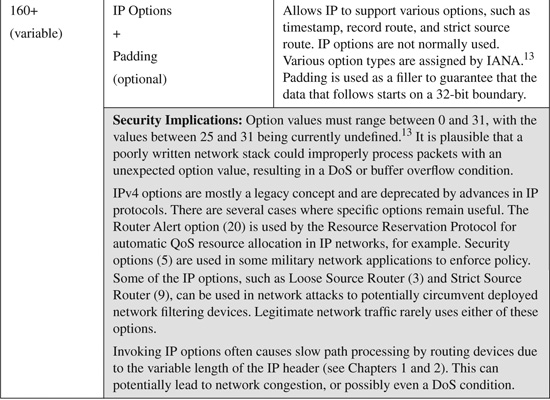
The minimum IP version 4 (IPv4) packet header consists of 12 fields requiring 20 bytes to specify the data necessary to route a packet. The IP header is capable of allowing an additional 13th field for specifying optional content to enable specialized services during routing. With certain exceptions, IPv4 options are not normally used. The IPv4 header is shown below in Figure B-1.
Figure B-1. IP Version 4 Header
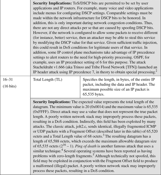
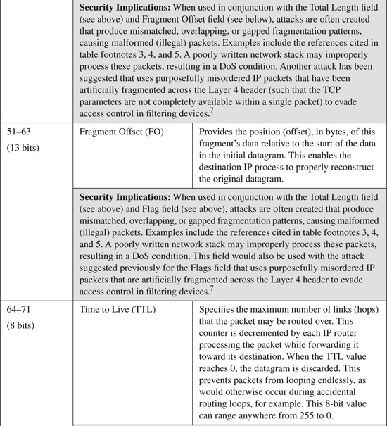
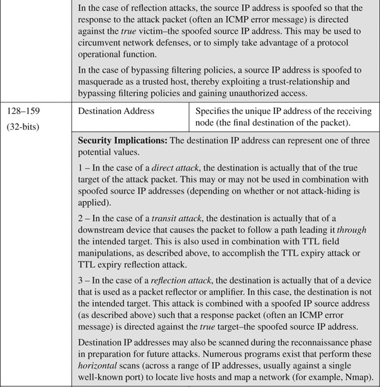
IPv4 header fields are listed and described in Table B-1. Table B-1 also includes a brief description of some known modifications or spoofs to relevant header fields that have been seen in common attacks.
Table B-1. IP Version 4 Header Fields and Their Security Implications


TCP Header
The minimum Transmission Control Protocol (TCP) header consists of ten fields requiring 20 bytes to specify the data necessary to establish and maintain this connection-oriented session. The TCP header is capable of allowing an additional 11th field for specifying optional content to enable specialized services for the session. The TCP header is shown in Figure B-2.

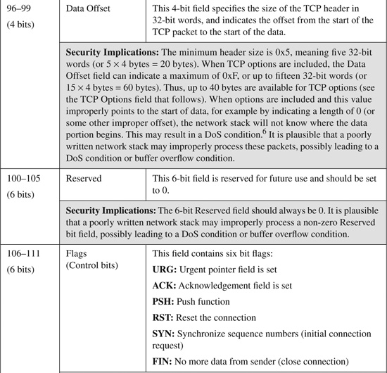
The TCP header fields shown in Figure B-2 are listed and described in Table B-2. Table B-2 also provides a brief description of some known modifications or spoofs to relevant header fields that have been seen in common attacks.
Note
TCP is a complex, connection-oriented Layer 4 protocol that is designed to provide the reliable delivery of its segments using the connectionless, best-effort networking (Layer 3) IP protocol. TCP uses many moving parts to support reliable data delivery. This section does not attempt to cover or address each and every one of these components. Additional TCP resources may be found in TCP/IP Illustrated, Volume 1, listed in the “Further Reading” section at the end of the appendix.
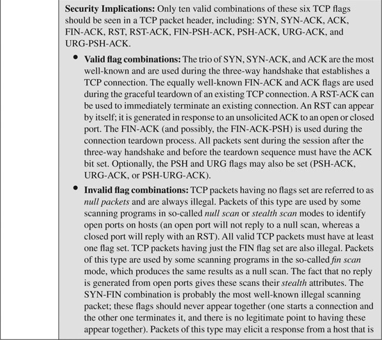
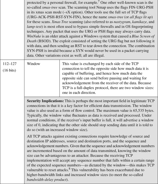
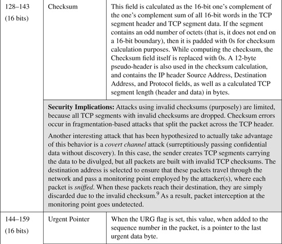
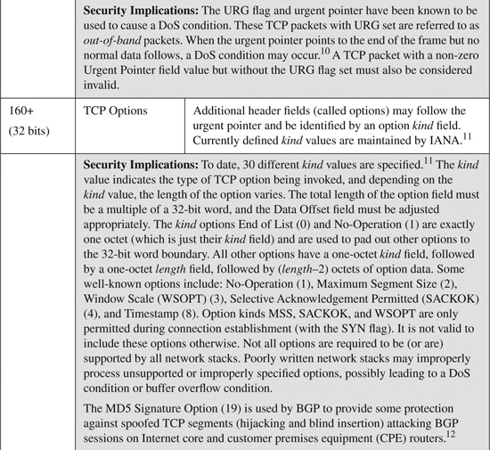
Table B-2. TCP Header Fields and Their Security Implications


UDP Header
The User Datagram Protocol (UDP) is used for unreliable, minimal overhead transport services that give applications direct access to the datagram service of the IP layer. UDP provides no guarantees for delivery and no protection from duplication. Its simplicity in implementation is its strength when considering transport overhead, but its weakness when considering security implications.
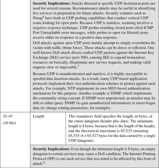
The UDP header consists of only four fields, of which two are optional, and requires 8 bytes to specify the necessary values. The UDP header is shown in Figure B-3.
Note
Because UDP is stateless, unauthenticated, and often used in unidirectional data flows, it is highly susceptible to spoofing attacks against nearly every port and every service. This section does not attempt to cover or address each and every type of UDP attack known to exist.
The UDP header fields shown in Figure B-3 are listed and described in Table B-3. Table B-3 also provides a brief description of some known modifications or spoofs to relevant header fields that have been seen in common attacks.
Table B-3. UDP Header Fields and Their Security Implications


ICMP Header
The Internet Control Message Protocol (ICMP) is used for error reporting and debugging of the IP protocol. ICMP uses IP at the network layer and hence it is unreliable (by the same definition that IP is considered unreliable). In general, there are two types of ICMP messages:
• Query messages: ICMP query messages are generated by users or client programs and are used to probe the network and gather status information at any moment. Query messages are primarily intended for use as troubleshooting and diagnostic tools. For example, the ICMP Echo Request/Echo Reply function sends a packet with a specific payload to a destination host, where it is expected to be copied and returned to the sending host. The user application ping is the most familiar management tool that provides access to the ICMP Echo Request/Echo Reply function.
• Error messages: ICMP error messages are automatically generated by network elements or hosts when certain error conditions within the network are encountered. ICMP may, for example, announce that a host or a network is unreachable by issuing the ICMP Destination Unreachable message, or that a routing loop has occurred by issuing the ICMP Time Exceeded message.
In the previous protocol header examples, a single header could be used to fully describe each protocol. This is not the case with ICMP. Although a basic ICMP header format can be described, the full format and content of any individual ICMP query or error message varies with the type of ICMP message.
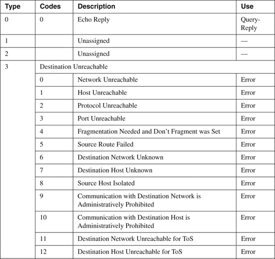
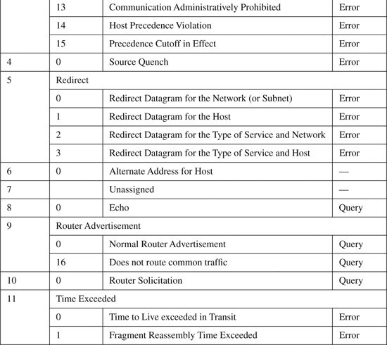
The basic ICMP header illustrated in Figure B-4 shows the major fields that are included in all ICMP messages. The primary fields are the 8-bit Type field, the adjacent 8-bit Code field, followed by the 16-bit ICMP Header Checksum. After that, a variable-format data field appears. The format and contents of this field depend on the ICMP message type. Valid ICMP message types, as defined by their type and code field values, are listed in Table B-4.
Table B-4. ICMP Message Types and Codes[1]
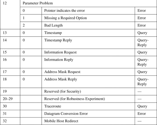
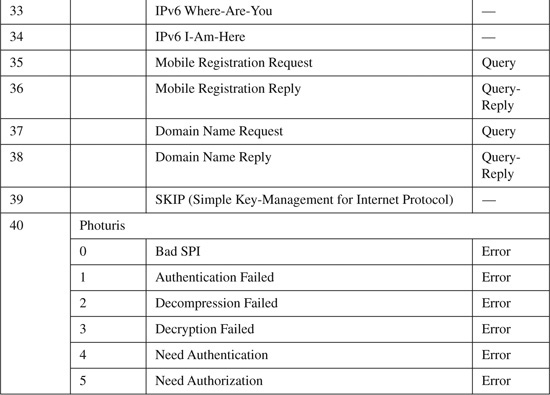
1. “ICMP Type Numbers.” IANA.
http://www.iana.org/assignments/icmp-parameters.
Although ICMP is a legitimate protocol and is required for the proper operations of IP networks, it has historically been one of the most exploited and exploitable protocols. The most commonly exploited ICMP message types are reviewed in the following four subsections.
ICMP Echo Request/Echo Reply Query Message Headers
The ICMP Echo Request/Echo Reply query messages (Type 8, Code 0 and Type 0, Code 0, respectively) function as a pair, with the Echo Request sending a packet with a specific payload to a destination host, where the payload is expected to be copied and returned to the sending host as an Echo Reply. The user application ping is the most familiar network management and diagnostic tool that provides access to the ICMP Echo Request/Echo Reply message function. Ping transmits a series of packets to a destination host, and then waits for their return. Based on how many are returned and the time it takes, ping computes average round-trip times and loss percentages. Hence, ping is the most widely used tool for verifying network connectivity, and IP reachability to destination hosts (or attack targets!).
Note
More-advanced network diagnostics can be performed with ping by modifying various IP header and ICMP header parameters. For example, setting the IP header Don’t Fragment (DF) bit and increasing the ICMP payload size can be used to identify locations along the packet path where fragmentation is required (due to smaller link MTUs). Ping typically allows for other parameters to be set as well, such as TTL, QoS markings, record-route IP options, and timestamp options.
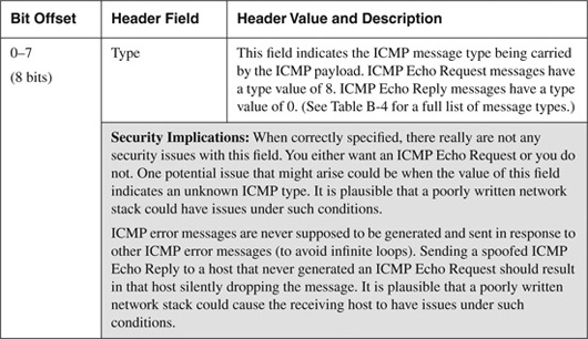
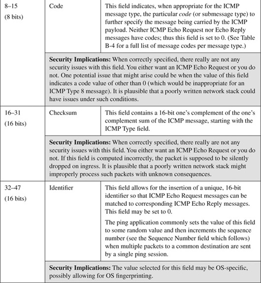
The ICMP Echo Request/Echo Reply header consists of five fields, plus a Data field, as shown in Figure B-5. The ICMP Echo Request/Echo Reply header fields shown in Figure B-5 are listed and described in Table B-5, along with a brief description of the security implications relevant to each header field.
Figure B-5. ICMP Header—Echo Request/Echo Reply Query Message
Table B-5. ICMP Echo Request/Echo Reply Header Fields and Their Security Implications


ICMP Time to Live Exceeded in Transit Error Message Header
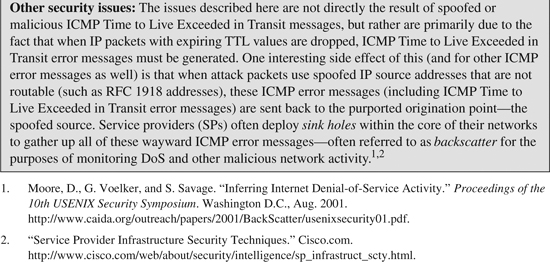
The ICMP Time to Live Exceeded in Transit error message (Type 11, Code 0) is generated by network elements that drop IP packets when they have a Time to Live (TTL) field value that decrements to 0 while in the forwarding process. Under normal circumstances, IP packets should be able to reach their destination within the allotted TTL scope. The TTL field is included within the IP header and is a means of preventing packets from “circling the network forever” (and clogging the Internet!) as would otherwise occur under a routing-loop condition, for example. When a packet is dropped during forwarding due to a TTL expiry condition, the ICMP Time to Live Exceeded in Transit error message is generated and sent back to the source IP address of the offending packet. In this case, a portion of the offending IP packet is also copied into the ICMP Time to Live Exceeded in Transit message payload as a feedback mechanism to the origination host.
The user application traceroute is the most familiar network management and diagnostic tool that purposefully takes advantage of this feedback mechanism. Traceroute maps the hop-by-hop path a packet would take through the network from source to destination by artificially manipulating the TTL field within an IP packet header to cause a TTL expiry at each node along the path. It then watches for the ICMP Time to Live Exceeded in Transit announcements in reply to map the entire path (in one direction).
The ICMP Time to Live Exceeded in Transit header consists of three fields, plus a data field, as shown in Figure B-6. The ICMP Time to Live Exceeded in Transit header fields shown in Figure B-6 are described in Table B-6, along with a brief description of the security implications relevant to each header field.
Figure B-6. ICMP Header—Time to Live Exceeded in Transit Error Message
Table B-6. ICMP Time to Live Exceeded in Transit Error Message Header Fields and Their Security Implications


ICMP Destination Unreachable, Fragmentation Needed and Don’t Fragment was Set Error Message Header
The ICMP Destination Unreachable, Fragmentation Needed and Don’t Fragment was Set (Type 3, Code 4) error message is generated by network elements that drop IP packets during the forwarding process when the router determines the following:
• The packet size exceeds the MTU of the forwarding interface.
• The packet DF bit is set (DF = 1) in the IP header, indicating that forwarding routers are not allowed to fragment the packet.
When IP packets with the DF bit set traverse the Internet (or any IP network) from source to destination, an ICMP Destination Unreachable, Fragmentation Needed and Don’t Fragment was Set error message can be generated anywhere along the path by any forwarding router when the preceding error condition occurs.
Note
Fragmentation should be avoided where possible. Most enterprises are using Ethernet-based links with an MTU of 1500 bytes, and most SPs are running IP core network links with an MTU of 4470 bytes or greater. IP packets should have little trouble traversing such networks, even if the DF bit is set. Fragmentation issues mainly result when tunnel encapsulations, such as IPsec, GRE, MPLS, or L2TPv3, are applied. In these cases, additional encapsulation protocol headers are added to the original packet, potentially resulting in oversized packets (as compared to the 1500-byte MTU). Methods to address these issues are described in Chapter 7, “IP Services Plane Security.”
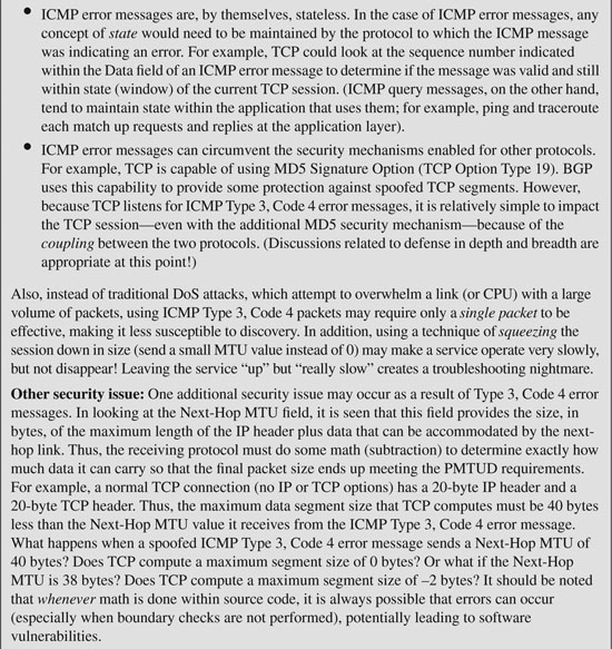
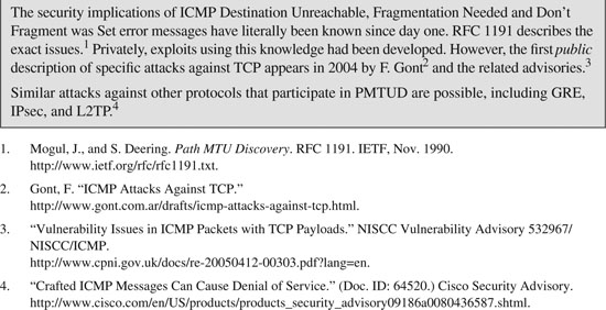
ICMP Destination Unreachable, Fragmentation Needed and Don’t Fragment was Set (Type 3, Code 4) error messages are used to support Path MTU Discovery (RFC 1191). The application or protocol that sent the offending packet is responsible for listening for ICMP Type 3, Code 4 error messages and adjusting future packet sizes accordingly.
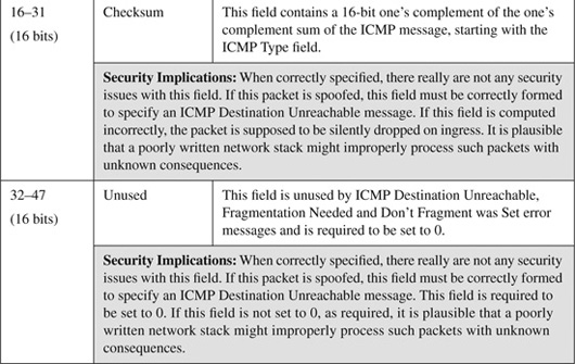
The ICMP Type 3, Code 4 header consists of five fields, plus a Data field, as shown in Figure B-7. The ICMP Type 3, Code 4 header fields shown in Figure B-7 are listed and described in Table B-7, along with a brief description of the security implications relevant to each header field.
Figure B-7. ICMP Header—Destination Unreachable, Fragmentation Needed and Don’t Fragment was Set Error Message
Table B-7. ICMP Destination Unreachable, Fragmentation Needed and Don’t Fragment was Set Header Fields and Their Security Implications


Other ICMP Destination Unreachable Error Message Headers
Under normal circumstances, IP packets should be able to reach their destination without incident. For a variety of reasons, this may not be the case, however. The ICMP Destination Unreachable (Type 3) error message header provides 16 different submessage categories (codes) to describe the various error conditions. The focus here is on four particularly useful Destination Unreachable error messages:
• ICMP Destination Unreachable, Network Unreachable (Type 3, Code 0): When a router cannot forward a packet because it has no routes at all (including no default route) to the destination specified in the packet, then the router may generate this ICMP message back to the host.
• ICMP Destination Unreachable, Host Unreachable (Type 3, Code 1): When a router cannot forward a packet to a host on a network that is directly connected to the router (in other words, the router is the last-hop router) and the router has ascertained that there is no path to the destination host, then the router must generate this ICMP message. In this scenario, the destination network exists, but the destination host within the network does not. If, for example, the last-hop router cannot resolve the MAC address for the destination address via ARP, it considers the host unreachable.
• ICMP Destination Unreachable, Port Unreachable (Type 3, Code 3): When a packet is received by the destination host and the indicated destination transport protocol (for example, UDP) is unable to associate the packet to a local port number, then the host should generate this ICMP message. In this scenario, the destination host may not be configured for servicing the specified protocol port number (for example, HTTP).
• ICMP Destination Unreachable, Communication Administratively Prohibited (Type 3, Code 13): When a router cannot forward a packet because a security policy (for example, an access list) has been applied that denies the packet from being forwarded, the router should generate this ICMP message.
The ICMP Destination Unreachable header consists of three fields, plus a Data field, as shown in Figure B-8. The ICMP Destination Unreachable header fields shown in Figure B-8 are listed and described in Table B-8, along with a brief description of the security implications relevant to each header field.
Figure B-8. ICMP Header—Destination Unreachable Error Messages

Table B-8. ICMP Destination Unreachable Error Message Header Fields and Their Security Implications


Ethernet/802.1Q Header
As outlined in Chapter 2, a wide variety of network attacks are accomplished by manipulating and spoofing the header fields within Layer 2 Ethernet frames. While there are several different variants, the two most common are the IEEE 802.3 Ethernet Frame, and the IEEE 802.1Q VLAN Frame. This section reviews these different Ethernet frame formats, their header fields, and associated security implications.
IEEE 802.3 Ethernet Frame Header Format
Ethernet operates at Layer 2 of the OSI protocol stack. The IEEE 802.3 standard defines a basic data frame format that is required for all Ethernet implementations, plus several additional optional formats that are used to extend the protocol’s basic capability.
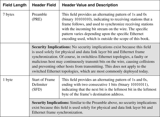
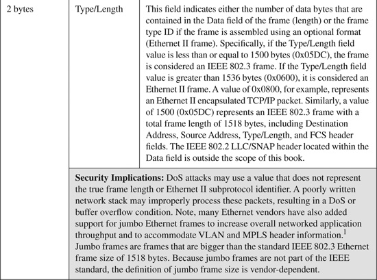
The basic IEEE 802.3 Ethernet frame format contains seven fields, as shown in Figure B-9. The IEEE 802.3 Ethernet frame header fields shown in Figure B-9 are described in Table B-9, along with a brief description of some known modifications or spoofs to relevant header fields that have been seen used in common Ethernet attacks.
Figure B-9. IEEE 802.3 Ethernet Frame Header

Table B-9. IEEE 802.3 Ethernet Frame Header Fields and Their Security Implications


IEEE 802.1Q VLAN Header Format
The IEEE 802.1Q VLAN header extends the IEEE 802.3 Ethernet protocol’s basic capability (see the Cisco Tech Note “Inter-Switch Link and IEEE 802.1Q Frame Format,” referenced in the “Further Reading” section). The IEEE 802.1Q VLAN header format consists of the original IEEE 802.3 Ethernet frame header, plus two additional 2-byte fields inserted as shown in Figure B-10. (A reference for IEEE 802.1Q is included in the “Further Reading” section.) The IEEE 802.1Q VLAN header fields shown in Figure B-10 are listed and described in Table B-10, along with a brief description of some known modifications or spoofs to relevant header fields that have been seen used in common VLAN attacks.
Figure B-10. IEEE 802.1Q VLAN Frame Header
Table B-10. IEEE 802.1Q VLAN Frame Header Fields and Their Security Implications


MPLS Protocol Header
MPLS is deployed for a variety of applications, including Layer 3 IP VPNs, Layer 2 VPNs, traffic engineering, and fast network convergence (reroute). Most current MPLS deployments are intradomain, where MPLS labeled packets are not exchanged between external or untrusted peers. With the growth of interdomain MPLS VPNs and Carrier Supporting Carrier (CsC) services, MPLS labeled packets are increasingly being exchanged at interprovider boundaries. This section reviews the MPLS label header formats, the label fields, and associated security implications.
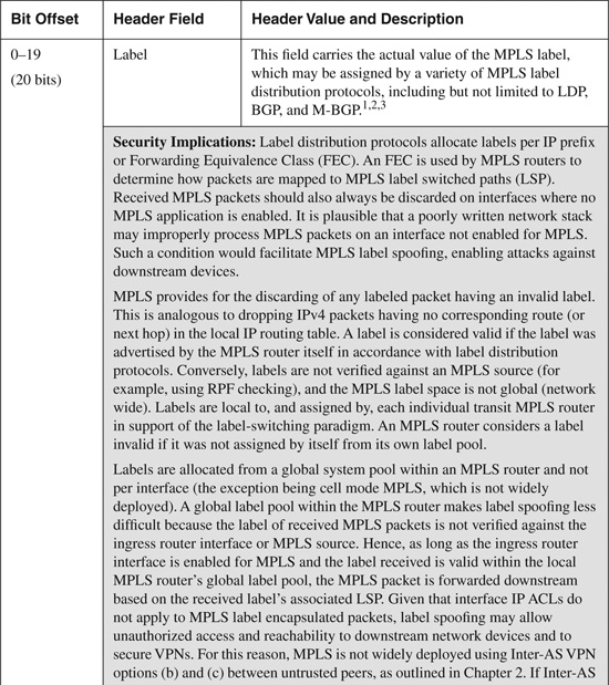
RFC 3032 and RFC 4182 define the MPLS label stack encoding (see the “Further Reading” section for links to these RFCs). For IP-based MPLS services, the MPLS header appears after the Layer 2 headers (for example, Ethernet) but before the IP packet, as shown in Figure B-11. The MPLS header is represented by a label stack that consists of a sequence of label stack entries. Each label stack entry is 4 bytes in length. The depth of the label stack often varies between MPLS networks and is dependent upon the MPLS services deployed (for example, MPLS VPNs, MPLS TE/FRR, and AToM). The MPLS label format contains four fields, as illustrated in Figure B-12. Each of these fields is listed and described in Table B-11, along with a brief description of applicable security considerations.
Figure B-11. MPLS Encapsulation Example of an IP Packet Transported over an Ethernet Interface
Figure B-12. MPLS Label Stack Encoding
![]()
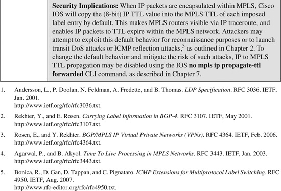
Table B-11. MPLS Label Fields and Security Considerations


Further Reading
Rosen, E., D. Tappan, G. Fedorkow, Y. Rekhter, D. Farinacci, T. Li, and A. Conta. MPLS Label Stack Encoding. RFC 3032. IETF, Jan. 2001. http://www.ietf.org/rfc/rfc3032.txt.
Rosen, E. Removing a Restriction on the Use of MPLS Explicit NULL. RFC 4182. IETF, Sept. 2005. http://www.ietf.org/rfc/rfc4182.txt.
Stevens, W. R.TCP/IP Illustrated, Volume 1. Addison-Wesley Professional, 1993. ISBN: 0-20163-346-9.
“Ethernet Technologies.” Internetworking Technology Handbook. Cisco Documentation. http://www.cisco.com/univercd/cc/td/doc/cisintwk/ito_doc/ethernet.htm.
IEEE 802.3 LAN/MAN CSMA/CD Access Method. IEEE 802.3-2005/COR 1-2006. IEEE, 2005. http://standards.ieee.org/getieee802/802.3.html.
IEEE 802.1Q-2003, Virtual Bridged Local Area Networks. IEEE, 2003. http://standards.ieee.org/getieee802/download/802.1Q-2005.pdf.
“Inter-Switch Link and IEEE 802.1Q Frame Format.” (Doc. ID: 17056.) Cisco Tech Note. http://www.cisco.com/en/US/tech/tk389/tk689/technologies_tech_note09186a0080094665.shtml.