Chapter 2. Introduction to Border Gateway Protocol 4
This chapter covers the following key topics:
• Classless Interdomain Routing—This section introduces CIDR and discusses both its advantages and its shortcomings.
• Who Needs BGP?—This section examines several inter-AS scenarios, with an eye to where BGP is necessary and where it is not.
• BGP Basics—This section discusses the fundamentals of the Border Gateway Protocol, including message types and path attributes.
• IBGP and IGP Synchronization—This section presents the issues surrounding synchronization between IBGP and the IGP within an AS, why synchronization is required by default, and how synchronization problems can be avoided.
• Managing Large-Scale BGP Peering—This section presents four tools for controlling large-scale BGP implementations.
• BGP Message Formats—This section examines the details of the various BGP messages.
Border Gateway Protocol (BGP) is a particularly important topic for any CCIE, and you can expect your knowledge of it to be thoroughly challenged in the CCIE lab.
You learned in Chapter 1, "Exterior Gateway Protocol," that the architects of the ARPANET began recognizing in the early 1980s that autonomous systems, and an inter-AS reachability protocol, were necessary to maintain manageability of the fast-growing Internet. Their original solution, Exterior Gateway Protocol (EGP), was adequate for the backbone-based ARPANET, but from the beginning, the architects understood the necessity of moving to a meshed inter-AS topology. They further understood that EGP was not capable of efficiently routing in such an environment because of its inability to detect loops, its very slow convergence time, and its lack of tools to support routing policies.
Attempts were made to enhance EGP, but in the end, an entirely new inter-AS protocol, a true routing protocol rather than a mere reachability protocol such as EGP, was called for. That inter-AS routing protocol, first introduced in 1989 in RFC 11051, is BGP. The first version of BGP was updated exactly one year later in RFC 11632. BGP was upgraded again in 1991 in RFC 12673, and with this third modification, it became customary to refer to the three versions as BGP-1, BGP-2, and BGP-3, respectively.
The current version of BGP, BGP-4, was introduced in 1995 in RFC 17714. BGP-4 differs significantly from the earlier versions. The most important difference is that BGP-4 is classless, whereas the earlier versions are classful. The motive for this fundamental change goes to the very heart of the reason exterior gateway protocols exist at all: to keep routing within the Internet both manageable and reliable. Classless interdomain routing (CIDR)—originally introduced in RFC 15175 in 1993, finalized in RFC 15196 in the same year as a standard proposal, and amended by RFC 15207—was created for this purpose, and BGP-4 was created to support CIDR.
Classless Interdomain Routing
The invention of autonomous systems and exterior routing protocols solved the early scalability problems on the Internet in the 1980s. However, by the early 1990s the Internet was beginning to present a different set of scalability problems, including the following:
• Explosion of the Internet routing tables. The exponentially growing routing tables were becoming increasingly unmanageable both by the routers of the time and the people who managed them. The mere size of the tables was burden enough on Internet resources, but day-to-day topological changes and instabilities added heavily to the load.
• Depletion of the Class B address space. In January 1993, 7133 of the 16,382 available Class B addresses had been assigned; at 1993 growth rates, the entire Class B address space would be depleted in less than 2 years (as cited in RFC 1519).
• The eventual exhaustion of the entire 32-bit IP address space.
Classless interdomain routing provides a short-term solution to the first two problems. Another short-term solution is network address translation (NAT), discussed in Chapter 4, "Network Address Translation." These solutions were intended to buy the Internet architects enough time to create a new version of IP with enough address space for the foreseeable future. That initiative, known as IP Next Generation (IPng), resulted in the creation of IPv6, with a 128-bit address format. IPv6, discussed in Chapter 8, "IP Version 6," is the long-term solution to the third problem. Interestingly, CIDR and NAT have been so successful that few people place as much urgency on the migration to IPv6 as they once did.
CIDR is merely a politically sanctioned address summarization scheme that takes advantage of the hierarchical structure of the Internet. So before discussing CIDR further, a review of summarization and classless routing, and a look at the modern Internet, are in order.
A Summarization Summary
Summarization or route aggregation (discussed extensively in Routing TCP/IP, Volume I) is the practice of advertising a contiguous set of addresses with a single, less-specific address. Basically, summarization/route aggregation is accomplished by reducing the length of the subnet mask until it masks only the bits common to all the addresses being summarized. In Figure 2-1, for example, the four subnets (172.16.100.192/28, 172.16.100.208/28, 172.16.100.224/28, and 172.16.100.240/28) are summarized with the single aggregate address 172.16.100.192/26.
Figure 2-1 Route Aggregation
Many networkers who view summarization as a difficult topic are surprised to learn that they use summarization daily. What is a subnet address, after all, other than a summarization of a contiguous group of host addresses? For example, the subnet address 192.168.5.224/27 is the aggregate of host addresses 192.168.5.224/32 through 192.168.5.255/32. (The "host address" 192.168.5.224/32 is, of course, the address of the data link itself.) The key characteristic of a summary address is that its mask is shorter than the masks of the addresses it is summarizing. The ultimate summary address is the default address, 0.0.0.0/0, commonly written as just 0/0. As the /0 indicates, the mask has shrunk until no network bits remain—the address is the aggregate of all IP addresses.
Summarization can also cross class boundaries. For example, the four Class C networks (192.168.0.0, 192.168.1.0, 192.168.2.0, and 192.168.3.0) can all be summarized with the aggregate address 192.168.0.0/22. Notice that the aggregate, with its 22-bit mask, is no longer a legal Class C address. Therefore, to support the aggregation of major class network addresses, the routing environment must be classless.
Classless Routing
Classless routing features two aspects:
• Classlessness can be a characteristic of a routing protocol.
• Classlessness can be a characteristic of a router.
Classless routing protocols carry, as part of the routing information, a description of the network portion of each advertised address. The network portion of a network address is commonly referred to as the address prefix. An address prefix can be described by including an address mask, a length field that indicates how many bits of the address are prefix bits, or by including only the prefix bits in the update (see Figure 2-2). The classless IP routing protocols are RIP-2, EIGRP, OSPF, Integrated IS-IS, and BGP-4.

Figure 2-2 Advertising an Address Prefix with a Classless Routing Protocol
A classful router records destination addresses in its routing table as major class networks and subnets of those networks. When it performs a route lookup, it first looks up the major class network address and then tries to find a match in its list of subnets under that major address. A classless router ignores address classes and merely attempts a "longest match." That is, for any given destination address, it chooses the route that matches the most bits of the address. Take the routing table of Example 2-1, for instance, which shows several variably subnetted IP networks. If the router is classless, it attempts to find the longest match for each destination address.
Example 2-1 A Routing Table Containing Several Variably Subnetted IP Networks
Cleveland#show ip route
Codes: C - connected, S - static, I - IGRP, R - RIP, M - mobile, B - BGP
D - EIGRP, EX - EIGRP external, O - OSPF, IA - OSPF inter area
E1 - OSPF external type 1, E2 - OSPF external type 2, E - EGP
i - IS-IS, L1 - IS-IS level-1, L2 - IS-IS level-2, * - candidate default
Gateway of last resort is 192.168.2.130 to network 0.0.0.0
O E2 192.168.125.0 [110/20] via 192.168.2.2, 00:11:19, Ethernet0
O 192.168.75.0 [110/74] via 192.168.2.130, 00:11:19, Serial0
O E2 192.168.8.0 [110/40] via 192.168.2.18, 00:11:19, Ethernet1
192.168.1.0 is variably subnetted, 3 subnets, 3 masks
O E1 192.168.1.64 255.255.255.192
[110/139] via 192.168.2.134, 00:11:20, Serial1
O E1 192.168.1.0 255.255.255.128
[110/139] via 192.168.2.134, 00:00:34, Serial1
O E2 192.168.1.0 255.255.255.0
[110/20] via 192.168.2.2, 00:11:20, Ethernet0
192.168.2.0 is variably subnetted, 4 subnets, 2 masks
C 192.168.2.0 255.255.255.240 is directly connected, Ethernet0
C 192.168.2.16 255.255.255.240 is directly connected, Ethernet1
C 192.168.2.128 255.255.255.252 is directly connected, Serial0
C 192.168.2.132 255.255.255.252 is directly connected, Serial1
O E2 192.168.225.0 [110/20] via 192.168.2.2, 00:11:20, Ethernet0
O E2 192.168.230.0 [110/20] via 192.168.2.2, 00:11:21, Ethernet0
O E2 192.168.198.0 [110/20] via 192.168.2.2, 00:11:21, Ethernet0
O E2 192.168.215.0 [110/20] via 192.168.2.2, 00:11:21, Ethernet0
O E2 192.168.129.0 [110/20] via 192.168.2.2, 00:11:21, Ethernet0
O E2 192.168.131.0 [110/20] via 192.168.2.2, 00:11:21, Ethernet0
O E2 192.168.135.0 [110/20] via 192.168.2.2, 00:11:21, Ethernet0
O*E2 0.0.0.0 0.0.0.0 [110/1] via 192.168.2.130, 00:11:21, Serial0
O E2 192.168.0.0 255.255.0.0 [110/40] via 192.168.2.18, 00:11:22, Ethernet1
Cleveland#
If the router receives a packet with a destination address of 192.168.1.75, several entries in the routing table match the address: 192.168.0.0/16, 192.168.1.0/24, 192.168.1.0/25, and 192.168.1.64/26. The entry 192.168.1.64/26 is chosen (see Example 2-2) because it matches 26 bits of the destination address—the longest match.
Example 2-2 A Packet with a Destination Address of 192.168.1.75 Is Forwarded Out Interface S1
Cleveland#show ip route 192.168.1.75
Routing entry for 192.168.1.64 255.255.255.192
Known via "ospf 1", distance 110, metric 139, type extern 1
Redistributing via ospf 1
Last update from 192.168.2.134 on Serial1, 06:46:52 ago
Routing Descriptor Blocks:
* 192.168.2.134, from 192.168.7.1, 06:46:52 ago, via Serial1
Route metric is 139, traffic share count is 1
A packet with a destination address of 192.168.1.217 will not match 192.168.1.64/26, nor will it match 192.168.1.0/25. The longest match for this address is 192.168.1.0/24, as demonstrated in Example 2-3.
Example 2-3 The Router Cannot Match 192.168.1.217 to a More-Specific Subnet, So It Matches the Network Address 192.168.1.0/24
Cleveland#show ip route 192.168.1.217
Routing entry for 192.168.1.0 255.255.255.0
Known via "ospf 1", distance 110, metric 20, type extern 2, forward metric 10
Redistributing via ospf 1
Last update from 192.168.2.2 on Ethernet0, 06:48:18 ago
Routing Descriptor Blocks:
* 192.168.2.2, from 10.2.1.1, 06:48:18 ago, via Ethernet0
Route metric is 20, traffic share count is 1
The longest match that can be made for destination address 192.168.5.3 is the aggregate address 192.168.0.0/16, as demonstrated in Example 2-4.
Example 2-4 Packets Destined for 192.168.5.3 Do Not Match a More-Specific Subnet or Network, and Therefore Match the Supernet 192.168.0.0/16
Cleveland#show ip route 192.168.5.3
Routing entry for 192.168.0.0 255.255.0.0, supernet
Known via "ospf 1", distance 110, metric 139, type extern 1
Redistributing via ospf 1
Last update from 192.168.2.18 on Ethernet1, 06:49:26 ago
Routing Descriptor Blocks:
* 192.168.2.18, from 192.168.7.1, 06:49:26 ago, via Ethernet1
Route metric is 139, traffic share count is 1
Finally, a destination address of 192.169.1.1 will not match any of the network entries in the routing table, as demonstrated in Example 2-5. However, packets with this destination address are not dropped, because the routing table of Example 2-1 contains a default route. The packets are forwarded to next-hop router 192.168.2.130.
Example 2-5 No Match Is Found in the Routing Table for 192.169.1.1; Packets Destined for This Address Are Forwarded to the Default Address, Out Interface S0
Cleveland#show ip route 192.169.1.1
% Network not in table
Beginning with IOS 11.3, Cisco routers are classless by default. Prior to this release, the IOS defaults were classful. You can change the default with the ip classless command.
The routing table in Example 2-1 and the associated examples demonstrates another characteristic of longest-match routing. Namely, a route to an aggregate address does not necessarily point to every member of the aggregate. Figure 2-3 shows the vectors of the routes in Examples 2-2 through 2-5.

Figure 2-3 The Vectors of Routes in the Routing Table of Example 2-1
You can consider network 192.168.1.0/24 an aggregate of all its subnets; Figure 2-3 shows that the route to this network address directs packets out interface E0. Yet routes to two of its subnets, 192.168.1.0/25 and 192.168.1.64/26, point out a different interface, S1.
Note
In fact, 192.168.1.64/26 is itself a member of 192.168.1.0/25. The fact that there are distinct routes for these two addresses, both pointing out S1, hints that they are advertised by separate routers somewhere upstream.
Likewise, 192.168.1.0/24 is a member of the aggregate 192.168.0.0/16, but the route to that less-specific address is out E1. The least-specific route, 0.0.0.0/0, which is an aggregate of all other addresses, is out S0. Because of longest-match routing, packets to subnets 192.168.1.64/26 and 192.168.1.0/25 are forwarded out S1, whereas packets to other subnets of network 192.168.1.0/24 are forwarded out E0. Packets with destination addresses beginning with 192.168, other than 192.168.1, are forwarded out E1, and packets whose destination addresses do not begin with 192.168 are forwarded out S0.
Summarization: The Good, the Bad, and the Asymmetric
Summarization is a great tool for conserving network resources, from the amount of memory required to store the routing table to the amount of network bandwidth and router horsepower necessary to transmit and process routing information. Summarization also conserves network resources by "hiding" network instabilities.
For example, the network in Figure 2-4 has a flapping route—a route that, due to a bad physical connection or router interface, keeps transitioning down and up and down again.

Figure 2-4 A Flapping Route Can Destabilize the Entire Network
Without summarization, every time subnet 192.168.1.176/28 goes up or down, the information must be conveyed to every router in the corporate internetwork. Each of those routers, in turn, must process the information and adjust its routing table accordingly. If router Nashville advertises all the upstream routes with the aggregate address 192.168.1.128/25, however, changes to any of the more-specific subnets are not advertised past that router. Nashville is the aggregation point; the aggregate continues to be stable even if some of its members are not.
The price to be paid for summarization is a reduction in routing precision. In Example 2-6, interface S1 of the router in Figure 2-3 has failed, causing the routes learned from the neighbor on that interface to become invalid. Instead of dropping packets that would normally be forwarded out S1, however, such as a packet with a destination address of 192.168.1.75, the packet now matches the next-best route, 192.168.1.0/24, and is forwarded out interface E0. (Compare this to Example 2-2.)
Example 2-6 A Failed Route Can Lead to Inaccurate Packet Forwarding
Cleveland#
%LINEPROTO-5-UPDOWN: Line protocol on Interface Serial1, changed state to down
%LINK-3-UPDOWN: Interface Serial1, changed state to down
Cleveland#show ip route 192.168.1.75
Routing entry for 192.168.1.0 255.255.255.0
Known via "ospf 1", distance 110, metric 20, type extern 2, forward metric 10
Redistributing via ospf 1
Last update from 192.168.2.2 on Ethernet0, 00:00:20 ago
Routing Descriptor Blocks:
* 192.168.2.2, from 10.2.1.1, 00:00:20 ago, via Ethernet0
Route metric is 20, traffic share count is 1
Cleveland#
This imprecision may or may not be a problem, depending on what the rest of the internetwork looks like. Continuing with the example, suppose the next-hop router 192.168.2.2 still has a route entry to 192.168.1.64/26 via the router Cleveland, either because the internetwork has not yet converged or because the route was statically entered. In this case, a routing loop occurs. On the other hand, some router reachable via Cleveland’s E0 interface may have a "back door" route to subnet 192.168.1.64/26 that should be used only if the primary route, via Cleveland’s S1, becomes invalid. In this second case, the route to 192.168.1.0/24 has been designed as a backup route, and the behavior shown in Example 2-6 is intentional.
Figure 2-5 shows an internetwork in which a loss of routing precision can cause a different sort of problem. Here, routing domain 1 is connected to routing domain 2 by routers in San Francisco and Atlanta. What defines these domains is unimportant for the example. What is important is that all the networks in domain 1 can be summarized with the address 172.16.192.0/18, and all the networks in domain 2 can be summarized with the address 172.16.128.0/18.

Figure 2-5 When Multiple Routers Are Advertising the Same Aggregate Addresses, Loss of Routing Precision Can Become a Problem
Rather than advertise individual subnets, Atlanta and San Francisco advertise the summary addresses into the two domains. If a host on Dallas’ subnet 172.16.227.128/26 sends a packet to a host on Seattle’s subnet 172.16.172.32/28, the packet most likely is routed to Atlanta, because that is the closest router advertising domain 2’s summary route. Atlanta forwards the packet into domain 2, and it arrives at Seattle. When the host on subnet 172.16.172.32/28 sends a reply, Seattle forwards that packet to San Francisco—the closest router advertising the summary route 172.16.192.0/18.
The problem here is that the traffic between the two subnets has become asymmetric: Packets from 172.16.227.128/26 to 172.16.172.32/28 take one path, whereas packets from 172.16.172.32/28 to 172.16.227.128/26 take a different path. Asymmetry occurs because the Dallas and Seattle routers do not have complete routes to each other’s subnets. They have only routes to the routers advertising the summaries and must forward packets based on those routes. In other words, the summarization at San Francisco and Atlanta has hidden the details of the internetworks behind those routers.
Asymmetric traffic can be undesirable for several reasons. First, internetwork traffic patterns become unpredictable, making baselining, capacity planning, and troubleshooting more problematic. Second, link usage can become unbalanced. The bandwidth of some links can become saturated, while other links are underutilized. Third, a distinct variation can occur in the delay times of outgoing traffic and incoming traffic. This delay variation can be detrimental to some delay-sensitive applications such as voice and live video.
The Internet: Still Hierarchical After All These Years
Although the Internet has grown away from the single-backbone architecture of the ARPANET described in Chapter 1, it retains a certain hierarchical structure. At the lowest level, Internet subscribers connect to an Internet service provider (ISP). In many cases, that ISP is one of many small providers in the local geographic area (called local ISPs). For example, there are presently almost 200 ISPs in Colorado’s 303 area code. These local ISPs in turn are the customers of larger ISPs that cover an entire geographic region such as a state or a group of adjacent states. These larger ISPs are called regional service providers. Examples in Colorado are CSD Internet and Colorado Supernet. The regional service providers, in turn, connect to large ISPs with high-speed (DS-3 or OS-3 or better) backbones spanning a national or global area. These largest providers are the network service providers and include companies such as MCI/WorldCom (UUNET), SprintNet, Cable & Wireless, Concentric Network, and PSINet. More commonly, these various providers are referred to as Tier III, Tier II, and Tier I providers, respectively.
Figure 2-6 shows how these different types of ISPs are interrelated. In each case, a subscriber—whether an end user or a lower-level service provider—connects to a higher-level service provider at that ISP’s Point of Presence (POP). A POP is just a nearby router to which the subscriber can connect via dialup or a dedicated local loop. At the highest level, the network service providers interconnect via network access points (NAPs). A NAP is a LAN or switch—typically Ethernet, FDDI, or ATM—across which different providers can exchange routes and data traffic.
Figure 2-6 ISP/NAP Hierarchy
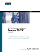
As Table 2-1 shows, some NAPs are known by names such as Commercial Internet Exchange (CIX), Federal Internet Exchange (FIX), and Metropolitan Area Exchange (MAE—originally called Metropolitan Area Ethernets, a creation of Metropolitan Fiber Systems, Inc.). CIX, FIX, and MAE-East were early experiments to connect backbones; based on the experience gained from these connection points, the National Science Foundation implemented the first four NAPs in 1994 as part of the decommissioning of the NSFnet.
Table 2-1 Well-Known Network Access Points in the United States
In addition to the major NAPs shown in Table 2-1, where the NSPs come together, there are many smaller NAPs. These usually interconnect smaller regional providers. Examples of regional NAPs are Seattle Internet eXchange (SIX) and the New Mexico network access point.
In conjunction with the formation of the NAPs, the NSF funded the Routing Arbiter (RA) project. One of the duties of the RA is to promote Internet stability and manageability. To this end, the RA proposed a database (the RADB, or Routing Arbiter Database) of routes (topology) and policies (preferred paths) from the service providers. The database is maintained at NAPs on a route server, a UNIX workstation or server running BGP. Rather than peering with every other router at the NAP, each provider’s router peers with only the route server. Routes and policies are communicated to the server, which uses a sophisticated database language called RIPE-181 to process and maintain the information. The appropriate routes are then passed to the other routers.
Although the route server speaks BGP and processes routes, it does not perform packet forwarding. Instead, its updates inform routers of the best next-hop router that is directly reachable across the NAP. You are already familiar with this concept from the discussion in Chapter 1 of EGP third-party neighbors. By making one-to-many peering feasible rather than many-to-many peering, route servers increase the stability, manageability, and throughput of traffic through the NAPs.
The NAPs and the RA project proved that the competing network service providers could cooperate to provide manageable connectivity and stability to the Internet. As a result, the NSF ceased funding of the route servers and NAPs on January 1, 1997, and turned the operations over to the commercial interests. Although publicly funded Internet research continues with such projects as Internet2, GigaPOPs, and the very high-speed Backbone Network Service (vBNS), the present Internet can be considered a commercial operation.
A result of the transition to commercial control of the Internet is that the topology of the modern Internet is far from the tidy picture drawn by the preceding paragraphs. The largest service providers, driven by financial, competitive, and policy interests, generally choose to peer directly rather than peer through route servers. The peering also takes place at many levels, rather than just at the top level shown in Figure 2-6.
When two or more service providers agree to share routes across a NAP, either directly or through a route server, they enter into a peering agreement. A peering agreement may be established directly between two providers (a bilateral peering agreement) or between a group of similar-sized providers (a multilateral peering agreement, or MLPA). Traffic patterns play a major role in determining the financial nature of the agreement. If the traffic between the peering partners is reasonably balanced in both directions, money usually does not exchange hands. The peering is equitable for the two partners. However, if the traffic is heavier in one direction than in the other across the peering point, as is the case when a small provider peers with a larger provider, the small provider usually must pay for the peering privilege. The rationale here is that the small provider benefits more from the peering than the larger provider.
Another factor muddling the Internet picture is the location of peering points. NAPs in which many providers come together, such as the ones listed in Table 2-1, are public peering sites. In addition to these public sites, service providers have created hundreds of smaller NAPs at sites where they find themselves co-located with other service providers. The peering agreements at such sites are usually private agreements between two or a few providers. Private peering is encouraged because it helps relieve congestion at the national NAPs, adds to route diversity, and can decrease delay for some traffic.
Another fact hinting that real life is not as tidy as Figure 2-6 suggests is that many national and regional service providers also sell local Internet access, in direct competition with the local ISPs. The "starting point" of the route traces in Example 2-7, for example, is a dial-in POP belonging to Concentric Network—a backbone provider. Regional service providers also frequently have a presence at the backbone NAPs. They might connect to one or more network service providers across the NAP, or they might connect to other regional service providers across the NAP, bypassing any network service provider.
The route traces in Example 2-7 show a little of the Internet backbone structure. Both traces originated from a Concentric Network POP in Denver. In the first trace, the packets traverse Concentric Network’s backbone to MAE-East, where they connect to the BBN Planet backbone (lines 3 and 4). The packets traverse BBN Planet’s backbone to a Tier II NAP shared by BBN and US West in Minneapolis (lines 10 and 11) and then are passed to the US West destination.
Example 2-7 Route Traces from a Concentric Network POP in Denver
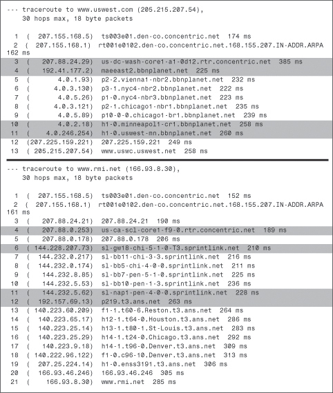
The packets in the second trace take a pretty thorough tour of the United States before arriving at their destination, a few miles from their origination. First, they follow Concentric’s backbone through a router in California (line 4) and then to the Chicago NAP, where they connect to the Sprint backbone (line 6). The packets are routed to the New York NAP in Pennsauken, New Jersey, where they are passed to the ANS backbone (lines 11 and 12). They then visit routers in Reston, Houston, St. Louis, and Chicago (again), and finally arrive back in Denver.
Like the packets in the last trace, we have taken a rather lengthy and circuitous route to get back to the topic at hand, CIDR.
CIDR: Reducing Routing Table Explosion
Given the somewhat hierarchical structure of the Internet, you can see how the structure lends itself to an address summarization scheme. At the top layers, large blocks of contiguous Class C addresses are assigned by the Internet Assigned Numbers Authority (IANA) to the various addressing authorities around the globe, known as the regional IP registries. Currently, there are three regional registries. The regional registry for North and South America, the Caribbean, and sub-Saharan Africa is the American Registry for Internet Numbers (ARIN). ARIN also is responsible for assigning addresses to the global network service providers. The regional registry for Europe, the Middle East, northern Africa, and parts of Asia (the area of the former Soviet Union) is the Resèaux IP Europèens (RIPE). The regional registry for the rest of Asia and the Pacific nations is the Asia Pacific Network Information Center (APNIC).
Note
ARIN was spun off of the InterNIC (run by Network Solutions, Inc.) in 1997 to separate the management of IP addresses and domain names.
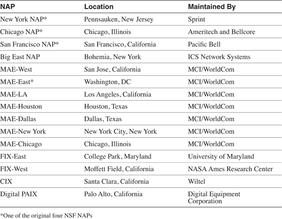
Table 2-2 shows the original scheme for assigning Class C addresses to the regions these registries serve, although some of the allocations are now outdated. As Example 2-8 demonstrates, the blocks labeled "Others" are now being assigned. The regional registries, in turn, assign portions of these blocks to the large service providers or to local IP registries. Generally, the blocks assigned at this level are no smaller than 32 contiguous Class C addresses (and are usually larger). Concentric Network has been assigned the block 207.155.128.0/17, for example, which includes the equivalent of 128 contiguous Class C addresses (see Example 2-8).
Table 2-2 CIDR Address Allocation by Geographic Region

Example 2-8 When a WHOIS Is Performed on the Address 207.155.128.5 from Example 2-7, the Address Is Shown as Part of a /17 CIDR Block Assigned to Concentric Network

The service providers receiving these blocks assign them in smaller blocks to their subscribers. If those subscribers are themselves ISPs, they can again break their blocks into smaller blocks. The obvious advantage of assigning these blocks of Class C addresses, called CIDR blocks, comes when the blocks are summarized back up the hierarchy. For more information on how addresses are assigned throughout the Internet, see RFC 2050 (www.isi.edu/in-notes/rfc2050.txt).
To illustrate, suppose Concentric Network assigns to one of its subscribers a portion of its 207.155.128.0/17 block, consisting of 207.155.144.0/20. If that subscriber is an ISP, it may assign a portion of that block, say 207.155.148.0/22, to one of its own subscribers. That subscriber advertises its /22 (read "slash twenty-two") block back to its ISP. That ISP in turn summarizes all of its subscribers to Concentric Network with the single aggregate 207.155.144.0/20, and Concentric Network summarizes its subscribers into the NAPs to which it is attached with the single aggregate 207.155.128.0/17.
The advertisement of a single aggregate to the higher-level domain is obviously preferable to advertising possibly hundreds of individual addresses. But an equally important benefit is the stability such a scheme adds to the Internet. If the state of a network in a low-level domain changes, that change is felt only up to the first aggregation point and no further.
Table 2-3 shows the different sizes of CIDR blocks, their equivalent size in Class C networks, and the number of hosts each block can represent.

CIDR: Reducing Class B Address Space Depletion
The depletion of Class B addresses was due to an inherent flaw in the design of the IP address classes. A Class C address provides 254 host addresses, whereas a Class B address provides 65,534 host addresses. That’s a wide gap. Before CIDR, if your company needed 500 host addresses, a Class C address would not have served your needs. You probably would have requested a Class B address, even though you would be wasting 65,000 host addresses. With CIDR, your needs can be met with a /23 block. The host addresses that would have otherwise been wasted have been conserved.
Difficulties with CIDR
Although CIDR has proven successful in slowing both the growth of Internet routing tables and the depletion of Class B addresses, it also has presented some problems for the users of CIDR blocks.
The first problem is one of portability. If you have been given a CIDR block, the addresses are most likely part of a larger block assigned to your ISP. Suppose, however, that your ISP is not living up to your expectations or contractual agreements, or you have just gotten a more attractive offer from another ISP. A change of ISPs most likely means you must re-address. It’s unlikely that an ISP will allow a subscriber to keep its assigned block when the subscriber moves to a new provider. Aside from an ISP’s being unwilling to give away a portion of its own address space, regional registries strongly encourage the return of address space when a subscriber changes ISPs.
For an end user, re-addressing carries varying degrees of difficulty. The process is probably the easiest for those who use private address space within their routing domain and network address translation (see Chapter 4) at the edges of the domain. In this case, only the "public-facing" addresses have to be changed, with minimal impact on the internal users. At the other extreme are end users who have statically assigned public addresses to all their internal network devices. These users have no choice but to visit every device in the network to re-address.
Even if the end user is using the CIDR block throughout the domain, the pain of re-addressing can be somewhat reduced by the use of DHCP (or BOOTP). In this case, the DHCP scopes must be changed and users must reboot, but only some statically addressed network devices, such as servers and routers, must be individually re-addressed.
The problem is much amplified if you are an ISP rather than an end user and you want to change your upstream service provider. Not only must your own internetwork be renumbered, but so must any of your subscribers to whom you have assigned a portion of your CIDR block.
CIDR also presents a problem to anyone who wants to connect to multiple service providers. Multihoming (discussed in more depth later in this chapter) is used for redundancy so that an end user or ISP is not vulnerable to the failure of a single upstream service provider. The trouble is that if your addresses are taken from one ISP’s block, you must advertise those addresses to the second provider.
Figure 2-7 shows what can happen. Here, the subscriber has a /23 CIDR block that is part of ISP1’s larger /20 block. When the subscriber attaches to ISP2, he wants to ensure that traffic from the Internet can reach him through either ISP1 or ISP2. To make this happen, he must advertise his /23 block through ISP2. The trouble arises when ISP2 advertises the /23 block to the rest of the world. Now all the routers "out there" have a route to 205.113.48.0/20 advertised by ISP1 and a route to 205.113.50.0/23 advertised by ISP2. Any packets destined for the subscriber are forwarded on the more-specific route, and as a result, almost all traffic from the Internet to the subscriber is routed through ISP2—including traffic from sources that are geographically much closer to the subscriber through ISP1.
Figure 2-7 Incoming Internet Traffic Matches the Most-Specific Route
In Figure 2-7, it is even possible for the 205.113.50.0/23 route to be advertised into ISP1 from the Internet. This shouldn’t happen, because most ISPs set route filters to prevent their own routes from reentering their domain. However, there are no guarantees that ISP1 is filtering properly. If the more-specific route should leak in from the Internet, traffic from ISP1’s other subscribers could traverse the Internet and ISP2 to 205.113.50.0/23 rather than take the more-direct path.
For the subscriber to be multihomed, ISP1 must advertise the more-specific route in addition to its own CIDR block (see Figure 2-8). Most service providers will not agree to this arrangement, because it means "punching a hole" in their own CIDR block (sometimes called address leaking). In addition to reducing the overall effectiveness of CIDR, advertising a more-specific route of its own CIDR block carries an administrative burden for the ISP.
Figure 2-8 ISP1 "Punches a Hole" in Its CIDR Block
Although Figures 2-7 and 2-8 show ISP1 as having only a single connection to the Internet, in most cases an ISP has many connections to higher-level providers and at NAPs. At each of these connections, the provider must reconfigure its router to advertise the more-specific route in addition to the CIDR block, and possibly must modify all its incoming route filters. Administration is also complicated by the fact that ISP1 and ISP2 have to closely coordinate their efforts to ensure that the subscriber’s /23 block is advertised correctly. Because ISP1 and ISP2 are competitors, either or both might be resistant to working so closely together.
Even if the subscriber in Figure 2-8 can get ISP1 and ISP2 to agree to advertise its own /23 block, there is another obstacle. Some Tier I providers accept only prefixes of /19 or smaller, to control the backbone-level routing tables. If ISP1 or ISP2 or both get their Internet connectivity from one of these network service providers, they cannot advertise the subscriber’s /23. The practice of filtering any CIDR addresses with a prefix larger than /19 has become so well-known that a /19 prefix is commonly referred to as a globally routable address. The implication here is that if you advertise a longer CIDR prefix, say a /21 or /22, your prefix might not be advertised to all parts of the Internet. Remember that any parts of the Internet that do not know how to reach you are essentially unreachable by you.
Note
Many Tier I providers have relaxed their /19 rules recently in response to increased subscriber complaints.
A possible solution for the multihomed subscriber in Figure 2-8 is to obtain a provider-independent address space (also known as a portable address space). That is, the subscriber can apply for a block that is not a part of either ISP1’s or ISP2’s CIDR block; both ISPs can advertise the subscriber’s block without interference with their own address space. Since the formation of ARIN, obtaining a provider-independent block is somewhat easier than it was under the InterNIC. Although ARIN strongly encourages you to seek an address space first from your provider and second from your provider’s provider, obtaining a provider-independent address space from ARIN is a last resort. However, you still face difficulties.
First, if you want to multihome, it is likely that your present address space was obtained from your original ISP. Changing to a provider-independent address space means renumbering, with all the difficulties already discussed. (Of course, if you obtained your IP address space in the pre-CIDR days, you are already provider-independent, making the question moot.)
Second, the registries assign address space based on justified need, not on long-term predicted need. This policy means that you probably will be allocated "just enough" space to fit your present needs and a three-month predicted need. From there, you have to justify a further allocation by proving that you are efficiently using the original space. For example, ARIN requires proof of address utilization by one of two means: the use of the Shared WHOIS Project (SWIP) or the use of a Referral WHOIS Server (RWHOIS). SWIP, most commonly used, is the practice of adding WHOIS information to a SWIP template and e-mailing it to ARIN. To use RWHOIS, you establish an RWHOIS server on your premises that ARIN can access for WHOIS information. In both cases, the WHOIS information establishes proof that you have efficiently used, and are approaching exhaustion of, your present address space.
Of course, you still have a problem if you cannot justify obtaining a globally routable (/19) address space. The bottom line is that CIDR allocation rules make multihoming a difficult problem for small subscribers and ISPs. The following section discusses multihoming in more detail, along with some alternative topologies.
Who Needs BGP?
Not as many internetworks need BGP as you might think. A common misconception is that whenever an internetwork must be broken into multiple routing domains, BGP should be run between the domains. BGP is certainly an option, but why complicate matters by unnecessarily adding another routing protocol to the mix?
Take, for example, a multinational corporate network consisting of 3000 routers and perhaps 150,000 users. Figure 2-9 shows how such a huge internetwork might be constructed. The entire network is routed with OSPF and is divided into eight geographic OSPF routing domains for easier manageability. Although the illustration shows only the backbone areas for each OSPF domain, each of the domains is divided into multiple OSPF areas that also correspond to geographic subregions.

Figure 2-9 Even a Very Large Internetwork Can Be Built Using Only Multiple IGP Domains
BGP can be used to provide connectivity between the multiple OSPF domains, but it is unnecessary. Instead, each of the eight OSPF backbone areas redistributes into a single global backbone. The global backbone is another OSPF domain, consisting of a single OSPF area. Although this core consists of high-end routers to handle the packet-switching load, the load on these routers from routing tables and OSPF processing is actually very small. Because of the way the entire internetwork is addressed, each of the eight OSPF domains advertises only a single aggregate route to the global backbone. In fact, aggregation is fundamental to making this design work. There are, presumably, such a large number of subnets in such an internetwork that without aggregation OSPF would "choke" trying to process them all. The result would be very poor performance and possible router failures.
The hierarchical construction of the physical topology and the address space are two of the three factors contributing to the simplicity of the internetwork in Figure 2-9. The third factor is a common administrative body for the entire internetwork. Having a single administration means that routing policies are imposed equally and consistently throughout. In this case, the routing policy dictates the address range used in each OSPF area and that all OSPF processes interconnect through OSPF 1 only.
Note
A routing policy is just a designed and configured process for controlling the traffic patterns within an internetwork by controlling routes and their characteristics. Redistribution, route filters, and route maps are the most common tools for implementing routing policies with Cisco IOS Software.
Of course, in real life, few corporations the size of the one depicted in Figure 2-9 have the luxury of being designed "from the ground up" in such a coordinated, logical fashion. Many, if not most, large internetworks have evolved from smaller internetworks that have been merged as divisions and corporations have merged. The result is that different network administrators have made different design choices for the various parts of the internetwork; when the parts are merged, the first order of business is basic interoperability.
The second order of business might be the enforcement of routing policies. Some traffic from some domains of the internetwork to other domains may be required to always prefer certain links or routes, for example, or perhaps only certain routes should be advertised between domains. In most cases, the necessary policies can still be implemented with redistribution between IGPs and tools such as route filters and route maps. You should implement BGP only when a sound engineering reason compels you to do so, such as when the IGPs do not provide the tools necessary to implement the required routing policies or when the size of the routing tables cannot be controlled with summarization. BGP proves useful, for instance, when many different IGPs are used in the domains. Here, BGP might be simpler to implement than attempting to redistribute among all the IGPs.
When considering whether BGP is necessary in an internetwork design, keep in mind why exterior routing protocols were invented in the first place. Exterior routing protocols are used to route between autonomous systems—that is, between internetwork domains under different administrative authorities. In a single corporate internetwork, even a large one with different domains under different local administrations, there is usually enough of a centralized authority to impose routing policy using the tools available with interior routing protocols. When separate autonomous systems must interconnect, however, BGP might be called for.
The majority of the cases calling for BGP involve Internet connectivity—either between a subscriber and an ISP or (more likely) between ISPs. Yet even when interconnecting autonomous systems, BGP might be unnecessary. The remainder of this section examines typical inter-AS topologies and demonstrates where BGP is and is not needed.
A Single-Homed Autonomous System
Figure 2-10 shows a subscriber attached by a single connection to an ISP. BGP, or any other type of routing protocol, is unnecessary in this topology. If the single link fails, no routing decision needs to be made, because no alternative route exists. A routing protocol accomplishes nothing. In this topology, the subscriber adds a static default route to the border router and redistributes the route into his AS.

Figure 2-10 Static Routes Are All That Is Needed in This Single-Homed Topology
The ISP similarly adds a static route pointing to the subscriber’s address range and advertises that route into its AS. Of course, if the subscriber’s address space is a part of the ISP’s larger address space, the route advertised by the ISP’s router goes no farther than the ISP’s own AS. "The rest of the world" reaches the subscriber by routing to the ISP’s advertised address space, and the more-specific route to the subscriber is picked up only within the ISP’s AS.
An important principle to remember when working with inter-AS traffic is that each physical link actually represents two logical links: one for incoming traffic and one for outgoing traffic (see Figure 2-11).

Figure 2-11 Each Physical Link Between Autonomous Systems Represents Two Logical Links, Carrying Incoming and Outgoing Packets
The routes you advertise in each direction influence the traffic separately. Avi Freedman, who has written many excellent articles on ISP issues, calls a route advertisement a promise to carry packets to the address space represented in the route. In Figure 2-10, the subscriber’s router is advertising a default route into the local AS—a promise to deliver packets to any destination for which there is not a more-specific route. And the ISP’s router, advertising a route to 205.110.32.0/20, is promising to deliver traffic to the subscriber’s AS. The outgoing traffic from the subscriber’s AS is the result of the default route, and the incoming traffic to the subscriber’s AS is the result of the route advertised by the ISP’s router. This concept might seem somewhat trivial and obvious at this point, but it is very important to keep in mind as you examine more-complex topologies.
The obvious vulnerability of the topology in Figure 2-10 is that the entire connection is made up of single points of failure. If the single data link fails, if a router or one of its interfaces fails, if the configuration of one of the routers fails, if a process within the router fails, or if one of the routers’ all-too-human administrators makes a mistake, the subscriber’s entire Internet connectivity can be lost. What is lacking in this picture is redundancy.
Multihoming to a Single Autonomous System
Figure 2-12 shows an improved topology, with redundant links to the same provider. How the incoming and outgoing traffic is manipulated across these links depends on how the two links are used. For example, a typical setup when multihoming to a single provider is for one of the links to be a primary, dedicated Internet access link—say, a T1—and for the other link to be used only for backup. In such a scenario, the backup link is likely to be some lower-speed connection.

Figure 2-12 Multihoming to a Single Autonomous System
When the redundant link is used only for backup, there is again no call for BGP. The routes can be advertised just as they were in the single-homed scenario, except that the routes associated with the backup link have the distances set high so that they are used only if the primary link fails.
Example 2-9 shows what the configurations of the routers carrying the primary and secondary links might look like.
Example 2-9 Primary and Secondary Link Configurations for Multihoming to a Single Autonomous System
Primary Router
router ospf 100
network 205.110.32.0 0.0.15.255 area 0
default-information originate metric 10
!
ip route 0.0.0.0 0.0.0.0 205.110.168.108
_________________________________________________________________________
Backup Router
router ospf 100
network 205.110.32.0 0.0.15.255 area 0
default-information originate metric 100
!
ip route 0.0.0.0 0.0.0.0 205.110.168.113 150
In this configuration, the backup router has a default route whose administrative distance is set to 150 so that it is in the routing table only if the default route from the primary router is unavailable. Also, the backup default is advertised with a higher metric than the primary default route to ensure that the other routers in the OSPF domain prefer the primary default route. The OSPF metric type of both routes is E2, so the advertised metrics remain the same throughout the OSPF domain. This consistency ensures that the metric of the primary default route remains lower than the metric of the backup default route in every router, regardless of the internal cost to each border router. Example 2-10 shows the default routes in a router internal to the OSPF domain.
Example 2-10 The First Display Shows the Primary External Route; the Second Display Shows the Backup Route Being Used After the Primary Route Has Failed

Although a primary/backup design satisfies the need for redundancy, it does not efficiently use the available bandwidth. A better design is to use both paths, with each providing backup for the other in the event of a link or router failure. In this case, the configuration used in both routers is as indicated in Example 2-11.
Example 2-11 Configuration for Load Sharing When Multihomed to the Same AS
router ospf 100
network 205.110.32.0 0.0.15.255 area 0
default-information originate metric 10 metric-type 1
!
ip route 0.0.0.0 0.0.0.0 205.110.168.108
The static routes in both routers have equal administrative distances, and the default routes are advertised with equal metrics (10). Notice that the default routes are now advertised with an OSPF metric type of E1. With this metric type, each of the routers in the OSPF domain takes into account the internal cost of the route to the border routers in addition to the cost of the default routes themselves. As a result, every router chooses the closest exit point when choosing a default route (see Figure 2-13).
Figure 2-13 Border Routers Advertising a Default Route with a Metric of 10 and an OSPF Metric Type of E1
In most cases, advertising default routes into the AS from multiple exit points, and summarizing address space out of the AS at the same exit points, is sufficient for good internetwork performance. The one consideration is whether asymmetric traffic patterns will become a concern. If the geographical separation between the two (or more) exit points is large enough for delay variations to become significant, you might have a need for better control of the routing. You might now consider BGP.
Suppose, for example, that the two exit routers depicted in Figure 2-12 are located in Los Angeles and London. You might want all your exit traffic destined for the Eastern Hemisphere to use the London router and all your exit traffic for the Western Hemisphere to use the Los Angeles router. Remember that the incoming route advertisements influence your outgoing traffic. If the provider advertises routes into your AS via BGP, your internal routers have more-accurate information about external destinations. BGP also provides the tools for setting routing policies for the external destinations.
Similarly, outgoing route advertisements influence your incoming traffic. If internal routes are advertised to the provider via BGP, you have influence over which routes are advertised at which exit point, and also tools for influencing (to some degree) the choices the provider makes when sending traffic into your AS.
When considering whether to use BGP, carefully weigh the benefits gained against the cost of added routing complexity. You should use BGP only when you can realize an advantage in traffic control. Consider the incoming and outgoing traffic separately. If it is only important to control your incoming traffic, use BGP to advertise routes to your provider while still advertising only a default route into your AS.
On the other hand, if it is only important to control your outgoing traffic, use BGP only to receive routes from your provider. Consider carefully the ramifications of accepting routes from your provider. "Taking full BGP routes" means that your provider advertises to you the entire Internet routing table. As of this writing, that is approximately 88,000 route entries, as shown in Example 2-12. To store and process a table of this size, you need a reasonably powerful router and at least 64 MB of memory (although 128 MB is recommended). On the other hand, you can easily implement a simple default routing scheme with a low-end router and a moderate amount of memory.
Example 2-12 This Full Internet Routing Table Summary Shows 57,624 BGP Entries

The routing table summary in Example 2-12 is taken from a publicly accessible route server at route-server.ip.att.net. Another server to which you can Telnet is route-server.cerf.net. The number of BGP entries varies somewhat in each, but all indicate a similar size.
"Taking partial BGP routes" is a compromise between taking full routes and accepting no routes at all. As the name implies, partial routes are some subset of the full Internet routing table. For example, a provider might advertise only routes to its other subscribers, plus a default route to reach the rest of the Internet. The following section presents a scenario in which taking partial routes proves useful.
Another consideration is that when running BGP, a subscriber’s routing domain must be identified with an autonomous system number. Like IP addresses, autonomous system numbers are limited and are assigned only by the regional address registries when there is a justifiable need. And like IP addresses, a range of autonomous system numbers is reserved for private use: the AS numbers 64512 to 65535. With few exceptions, subscribers that are connected to a single service provider (either single or multihomed) use an autonomous system number out of the reserved range. The service provider filters the private AS number out of the advertised BGP path.
Although the topology in Figure 2-12 is an improvement over the topology in Figure 2-10 because redundant routers and data links have been added, it still entails a single point of failure: the ISP itself. If the ISP loses connectivity to the rest of the Internet, so does the subscriber. And if the ISP suffers a major internal outage, the single-homed subscriber also suffers.
Multihoming to Multiple Autonomous Systems
Figure 2-14 shows a topology in which a subscriber has homed to more than one service provider. In addition to the advantages of multihoming already described, this subscriber is protected from losing Internet connectivity as the result of a single ISP failure.

Figure 2-14 Multihoming to Multiple Autonomous Systems
For a small corporation or a small ISP, there are substantial obstacles to multihoming to multiple service providers. You already have seen the problems involved if the subscriber’s address space is a part of one of the service providers’ larger address space:
• The originating provider must be persuaded to "punch a hole" in his CIDR block.
• The second provider must be persuaded to advertise an address space that belongs to a different provider.
• Both providers must be willing to closely coordinate the advertisement of the subscriber’s address space.
• If the subscriber’s address space is smaller than a /19 (which a small subscriber’s space is likely to be), some backbone providers might not accept the route.
The best candidates for multihoming to multiple providers are corporations and ISPs that are large enough to qualify for a provider-independent address space (or who already have one) and a public autonomous system number.
The subscriber in Figure 2-14 could still forego BGP. One option is to use one ISP as a primary Internet connection and the other as a backup only; another option is to default route to both providers and let the routing chips fall where they may. If a subscriber has gone to the expense of multihoming and contracting with multiple providers, however, neither of these solutions is likely to be acceptable. BGP is the preferred option in this scenario.
Again, incoming and outgoing traffic should be considered separately. For incoming traffic, the most reliability is realized if all internal routes are advertised to both providers. This setup ensures that all destinations within the subscriber’s AS are completely reachable via either ISP. Even though both providers are advertising the same routes, there are cases in which incoming traffic should prefer one path over another. BGP provides the tools for communicating these preferences.
For outgoing traffic, the routes accepted from the providers should be carefully considered. If full routes are accepted from both providers, the best route for every Internet destination is chosen. In some cases, however, one provider might be a preferred for full Internet connectivity, whereas the other provider is preferred for only some destinations. In this case, full routes can be taken from the preferred provider and partial routes can be taken from the other provider. For example, you might want to use the secondary provider, only to reach its other subscribers and for backup to your primary Internet provider (see Figure 2-15). The secondary provider sends its customer routes, and the subscriber configures a default route to the secondary ISP to be used if the connection to the primary ISP fails.

Figure 2-15 ISP1 Is the Preferred Provider for Most Internet Connectivity; ISP2 Is Used Only to Reach Its Other Customers’ Internetworks and for Backup Internet Connectivity
Notice that the full routes sent by ISP1 probably include the customer routes of ISP2. Because the same routes are received from ISP2, however, the subscriber’s routers normally prefer the shorter path through ISP2. If the link to ISP2 fails, the subscriber uses the longer paths through ISP1 and the rest of the Internet to reach ISP2’s customers.
Similarly, the subscriber normally uses ISP1 to reach all destinations other than ISP2’s customers. If some or all of those more-specific routes from ISP1 are lost, however, the subscriber uses the default route through ISP2.
If router CPU and memory limitations prohibit taking full routes, partial routes from both providers are an option. Each provider might send its own customer routes, and the subscriber points default routes to both providers. In this scenario, some routing accuracy is traded for a savings in router hardware.
In yet another partial-routes scenario, each ISP might send its customer routes and also the customer routes of its upstream provider. In Figure 2-16, for example, ISP1 is connected to Sprint, and ISP2 is connected to MCI. The partial routes sent to the subscriber by ISP1 consist of all of ISP1’s customer routes and all of Sprint’s customer routes. The partial routes sent by ISP2 consist of all of ISP2’s customer routes and all of MCI’s customer routes. The subscriber points to default routes at both providers. Because of the size of the two backbone service providers, the subscriber has enough routes to make efficient routing decisions on a large number of destinations. At the same time, the partial routes are still significantly smaller than a full Internet routing table.

Figure 2-16 The Subscriber Is Taking Partial Routes from Both ISPs, Consisting of Each ISP’s Customer Routes and the Customer Routes of Their Respective Upstream Providers
The remainder of this chapter (after two short cautionary sections) examines the operation of BGP and the tools it provides for setting preferences and policies for both incoming and outgoing traffic.
A Note on "Load Balancing"
The principal benefits of multihoming are redundancy and, to a lesser extent, increased bandwidth. Increased bandwidth does not mean that both links are used with equal efficiency. You should not expect the traffic load to be balanced 50/50 across the two links; one of the ISPs will almost always be "better connected" than the other ISP. The ISP itself or its upstream provider might have better routers, better physical links, or more NAP connections than the other ISP, or one ISP might just be topologically closer to more of the destinations to which your users regularly connect.
That is not to say that you cannot, through the expenditure of considerable time and effort, manipulate route preferences to fairly evenly balance your route traffic across the two links. The problem is that you probably actually degrade your Internet performance by forcing some traffic to take a less-optimal route for the sake of so-called load balancing. All you really accomplish, in most cases, is an evening out of the utilization numbers of your two ISP links. Do not be too concerned if 75 percent of your traffic uses one link while only 25 percent of your traffic uses the other link. Multihoming is for redundancy and increased routing efficiency, not load balancing.
BGP Hazards
Creating a BGP peering relationship involves an interesting combination of trust and mistrust. The BGP peer is in another AS, so you must trust the network administrator on that end to know what he or she is doing. At the same time, if you are smart, you will take every practical measure to protect yourself in the event that a mistake is made on the other end. When you’re implementing a BGP peering connection, paranoia is your friend.
Recall the earlier description of a route advertisement as a promise to deliver packets to the advertised destination. The routes you advertise directly influence the packets you receive, and the routes you receive directly influence the packets you transmit. In a good BGP peering arrangement, both parties should have a complete understanding of what routes are to be advertised in each direction. Again, incoming and outgoing traffic must be considered separately. Each peer should ensure that he is transmitting only the correct routes and should use route filters or other policy tools such as AS_PATH filters, described in Chapter 3, to ensure that he is receiving only the correct routes.
Your ISP might show little patience with you if you make mistakes in your BGP configuration, but the worst problems can be attributed to a failure on both sides of the peering arrangement. Suppose, for example, that through some misconfiguration you advertise 207.46.0.0/16 to your ISP. On the receiving side, the ISP does not filter out this incorrect route, allowing it to be advertised to the rest of the Internet. This particular CIDR block belongs to Microsoft, and you have just claimed to have a route to that destination. A significant portion of the Internet community could decide that the best path to Microsoft is through your domain. You will receive a flood of unwanted packets across your Internet connection and, more importantly, you will have black-holed traffic that should have gone to Microsoft. They will be neither amused nor understanding.
Figure 2-17 shows another example of a BGP routing mistake. This same internetwork was shown in Figure 2-15, but here the customer routes that the subscriber learned from ISP2 have been inadvertently advertised to ISP1.

Figure 2-17 This Subscriber Is Advertising Routes Learned from ISP2 into ISP1, Inviting Packets Destined for ISP2 and Its Customers to Transit His Domain
In all likelihood, ISP1 and its customers will see the subscriber’s domain as the best path to ISP2 and its customers. In this case, the traffic is not black-holed, because the subscriber does indeed have a route to ISP2. The subscriber has become a transit domain for packets from ISP1 to ISP2, to the detriment of its own traffic. And because the routes from ISP2 to ISP1 still point through the Internet, the subscriber has caused asymmetric routing for ISP2.
The point of this section is that BGP, by its very nature, is designed to allow communication between autonomously controlled systems. A successful and reliable BGP peering arrangement requires an in-depth understanding of not only the routes to be advertised in each direction, but also the routing policies of each of the involved parties.
BGP Basics
Like EGP, BGP forms a unique, unicast-based connection to each of its BGP-speaking peers. To increase the reliability of the peer connection, BGP uses TCP (port 179) as its underlying delivery mechanism. The update mechanisms of BGP are also somewhat simplified by allowing the TCP layer to handle such duties as acknowledgment, retransmission, and sequencing. Because BGP rides on TCP, a separate point-to-point connection to each peer must be established.
BGP is a distance vector protocol in that each BGP node relies on downstream neighbors to pass along routes from their routing table; the node makes its route calculations based on those advertised routes and passes the results to upstream neighbors. However, other distance vector protocols quantify the distance with a single number, representing hop count or, in the case of IGRP and EIGRP, a sum of total interface delays and lowest bandwidth. In contrast, BGP uses a list of AS numbers through which a packet must pass to reach the destination (see Figure 2-18). Because this list fully describes the path a packet must take, BGP is called a path vector routing protocol to contrast it with traditional distance vector protocols. The list of AS numbers associated with a BGP route is called the AS_PATH and is one of several path attributes associated with each route. Path attributes are described fully in a subsequent section.

Figure 2-18 BGP Determines the Shortest Loop-Free Inter-AS Path from a List of AS Numbers Known as the AS_PATH Attribute
Recall from Chapter 1 that EGP is not a true routing protocol because it does not have a fully developed algorithm for calculating the shortest path and it cannot detect route loops. In contrast, the AS_PATH attribute qualifies BGP as a routing protocol on both counts. First, the shortest inter-AS path is very simply determined by the least number of AS numbers. In Figure 2-18, AS7 is receiving two routes to 207.126.0.0/16. One of the routes has four AS hops, and the other has three hops. AS7 chooses the shortest path, (4,2,1).
Route loops also are very easily detected with the AS_PATH attribute. If a router receives an update containing its local AS number in the AS_PATH, it knows that a routing loop has occurred. In Figure 2-19, AS7 has advertised a route to AS8. AS8 advertises the route to AS9, which advertises it back to AS7. AS7 sees its own number in the AS_PATH and does not accept the update, thereby avoiding a potential routing loop.

Figure 2-19 If a BGP Router Sees Its Own AS Number in the AS_PATH of a Route from Another AS, It Rejects the Update
BGP does not show the details of the topologies within each AS. Because BGP sees only a tree of autonomous systems, it can be said that BGP takes a higher view of the Internet than IGP, which sees only the topology within an AS. And because this higher view is not really compatible with the view seen by IGPs, Cisco routers maintain a separate routing table to hold BGP routes. Example 2-13 demonstrates a typical BGP routing table viewed with the show ip bgp command.
Example 2-13 The show ip bgp Command Displays the BGP Routing Table
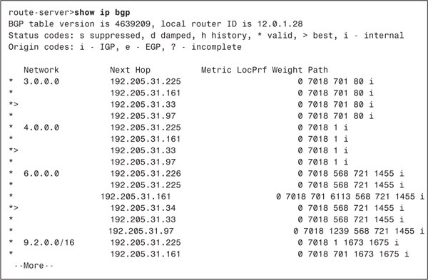
Although the BGP routing table in Example 2-13 looks somewhat different from the AS-internal routing table displayed with the show ip route command, the same elements exist. The table shows destination networks, next-hop routers, and a measure by which the shortest path can be selected. The Metric, LocPrf, and Weight columns are discussed later in this section, but what is of interest now is the Path column. This column lists the AS_PATH attributes for each network. Notice that each AS_PATH ends in an i, indicating that the path terminates at an IGP according to the Origin codes legend.
Notice also that for each destination network, multiple next hops are listed. Unlike the AS-internal routing table, which lists only the routes currently being used, the BGP table lists all known paths. A > following the * (valid) in the leftmost column indicates which path the router is currently using. This best path is the one with the shortest AS_PATH. When multiple routes have equivalent paths, as in the table of Example 2-13, the router must have some criteria for deciding which path to choose. That decision process is covered later in this section.
When there are parallel, equal-cost paths to a particular destination, as in Example 2-13, Cisco’s implementation of EBGP by default selects only one path—in contrast to other IP routing protocols, in which the default is to load balance across up to four paths. As with the other IP routing protocols, the maximum-paths command is used to change the default maximum number of parallel paths in the range from one to six. Note that load balancing works only with EBGP. IBGP can use only one link.
The neighbor with which a BGP speaker peers can be either in a different AS or in the same AS. If the neighbor’s AS differs, the neighbor is an external peer and the BGP is called external BGP (EBGP). If the neighbor is in the same AS, the neighbor is an internal peer and the BGP is called internal BGP (IBGP). A unique set of issues must be confronted when configuring IBGP; those issues are discussed in the section "IBGP and IGP Synchronization."
When two neighbors first establish a BGP peer connection, they exchange their entire BGP routing tables. After that, they exchange incremental, partial updates—that is, they exchange routing information only when something changes, and only information about what changed. Because BGP does not use periodic routing updates, the peers must exchange keepalive messages to ensure that the connection is maintained. The Cisco default keepalive interval is 60 seconds (RFC 1771 does not specify a standard keepalive time); if three intervals (180 seconds) pass without a peer receiving a keepalive message, the peer declares its neighbor down. You can change these intervals with the timers bgp command.
BGP Message Types
Before establishing a BGP peer connection, the two neighbors must perform the standard TCP three-way handshake and open a TCP connection to port 179. TCP provides the fragmentation, retransmission, acknowledgment, and sequencing functions necessary for a reliable connection, relieving BGP of those duties. All BGP messages are unicast to the one neighbor over the TCP connection.
BGP uses four message types:
• Open
• Keepalive
• Update
• Notification
This section describes how these messages are used; for a complete description of the message formats and the variables of each message field, see the section "BGP Message Formats."
Open Message
After the TCP session is established, both neighbors send Open messages. Each neighbor uses this message to identify itself and to specify its BGP operational parameters. The Open message includes the following information:
• BGP version number—This specifies the version (2, 3, or 4) of BGP that the originator is running. Unless a router is set to run an earlier version with the neighbor version command, it defaults to BGP-4. If a neighbor is running an earlier version of BGP, it rejects the Open message specifying version 4; the BGP-4 router then changes to BGP-3 and sends another Open message specifying this version. This negotiation continues until both neighbors agree on the same version.
• Autonomous system number—This is the AS number of the originating router. It determines whether the BGP session is EBGP (if the AS numbers of the neighbors differ) or IBGP (if the AS numbers are the same).
• Hold time—This is the maximum number of seconds that can elapse before the router must receive either a Keepalive or an Update message. The hold time must be either 0 seconds (in which case, Keepalives must not be sent) or at least 3 seconds; the default Cisco hold time is 180 seconds. If the neighbors’ hold times differ, the smaller of the two times becomes the accepted hold time.
• BGP identifier—This is an IP address that identifies the neighbor. The Cisco IOS determines the BGP Identifier in exactly the same way as it determines the OSPF router ID: The numerically highest loopback address is used; if no loopback interface is configured with an IP address, the numerically highest IP address on a physical interface is selected.
• Optional parameters—This field is used to advertise support for such optional capabilities as authentication, multiprotocol support, and route refresh.
Keepalive Message
If a router accepts the parameters specified in its neighbor’s Open message, it responds with a Keepalive. Subsequent Keepalives are sent every 60 seconds by Cisco default, or a period equal to one-third the agreed-upon hold time.
Update Message
The Update message advertises feasible routes, withdrawn routes, or both. The Update message includes the following information:
• Network Layer Reachability Information (NLRI)—This is one or more (Length, Prefix) tuples that advertise IP address prefixes and their lengths. If 206.193.160.0/19 were being advertised, for example, the Length portion would specify the /19 and the Prefix portion would specify 206.193.160.
• Path Attributes—The path attributes, described in a later section of the same name, are characteristics of the advertised NLRI. The attributes provide the information that allows BGP to choose a shortest path, detect routing loops, and determine routing policy.
• Withdrawn Routes—These are (Length, Prefix) tuples describing destinations that have become unreachable and are being withdrawn from service.
Note that although multiple prefixes might be included in the NLRI field, each update message describes only a single BGP route (because the path attributes describe only a single path, but that path might lead to multiple destinations). This, again, emphasizes that BGP takes a higher view of an internetwork than an IGP, whose routes always lead to a single destination IP address.
Notification Message
The Notification message is sent whenever an error is detected and always causes the BGP connection to close. The section "BGP Message Formats" includes a list of possible errors that can cause a Notification message to be sent.
An example of the use of a Notification message is the negotiation of a BGP version between neighbors. If, after establishing a TCP connection, a BGP-3 speaker receives an Open message specifying version 4, the router responds with a Notification message stating that the version is not supported. The connection is closed, and the neighbor attempts to reestablish a connection with BGP-3.
The BGP Finite State Machine
The stages of a BGP connection establishment and maintenance can be described in terms of a finite state machine. Figure 2-20 and Table 2-4 show the complete BGP finite state machine and the input events that can cause a state transition.

Figure 2-20 The BGP Finite State Machine
Table 2-4 The Input Events (IE) of Figure 2-20

The following sections provide a brief description of each of the six states illustrated in Figure 2-20.
Idle State
BGP always begins in the Idle state, in which it refuses all incoming connections. When a Start event (IE 1) occurs, the BGP process initializes all BGP resources, starts the ConnectRetry timer, initializes a TCP connection to the neighbor, listens for a TCP initialization from the neighbor, and changes its state to Connect. The Start event is caused by an operator configuring a BGP process or resetting an existing process, or by the router software resetting the BGP process.
An error causes the BGP process to transition to the Idle state. From there, the router may automatically try to issue another Start event. However, limitations should be imposed on how the router does this—constantly trying to restart in the event of persistent error conditions causes flapping. Therefore, after the first transition back to the Idle state, the router sets the ConnectRetry timer and cannot attempt to restart BGP until the timer expires. Cisco’s initial ConnectRetry time is 60 seconds. The ConnectRetry time for each subsequent attempt is twice the previous time, meaning that consecutive wait times increase exponentially.
Connect State
In this state, the BGP process is waiting for the TCP connection to be completed. If the TCP connection is successful, the BGP process clears the ConnectRetry timer, completes initialization, sends an Open message to the neighbor, and transitions to the OpenSent state. If the TCP connection is unsuccessful, the BGP process continues to listen for a connection to be initiated by the neighbor, resets the ConnectRetry timer, and transitions to the Active state.
If the ConnectRetry timer expires while in the Connect state, the timer is reset, another attempt is made to establish a TCP connection with the neighbor, and the process stays in the Connect state. Any other input event causes a transition to Idle.
Active State
In this state, the BGP process is trying to initiate a TCP connection with the neighbor. If the TCP connection is successful, the BGP process clears the ConnectRetry timer, completes initialization, sends an Open message to the neighbor, and transitions to OpenSent. The Hold timer is set to 4 minutes.
If the ConnectRetry timer expires while BGP is in the Active state, the process transitions back to the Connect state and resets the ConnectRetry timer. It also initiates a TCP connection to the peer and continues to listen for connections from the peer. If the neighbor is attempting to establish a TCP session with an unexpected IP address, the ConnectRetry timer is reset, the connection is refused, and the local process stays in the Active state. Any other input event (except a start event, which is ignored in the Active state) causes a transition to Idle.
OpenSent State
In this state, an Open message has been sent, and BGP is waiting to hear an Open from its neighbor. When an Open message is received, all its fields are checked. If errors exist, a Notification message is sent and the state transitions to Idle.
If no errors exist in the received Open message, a Keepalive message is sent and the Keepalive timer is set. The Hold time is negotiated, and the smaller value is agreed upon. If the negotiated Hold time is zero, the Hold and Keepalive timers are not started. The peer connection is determined to be either internal or external, based on the peer’s AS number, and the state is changed to OpenConfirm.
If a TCP disconnect is received, the local process closes the BGP connection, resets the ConnectRetry timer, begins listening for a new connection to be initiated by the neighbor, and transitions to Active. Any other input event (except a start event, which is ignored) causes a transition to Idle.
OpenConfirm State
In this state, the BGP process waits for a Keepalive or Notification message. If a Keepalive is received, the state transitions to Established. If a Notification is received, or a TCP disconnect is received, the state transitions to Idle.
If the Hold timer expires, an error is detected, or a Stop event occurs, a Notification is sent to the neighbor and the BGP connection is closed, changing the state to Idle.
Established State
In this state, the BGP peer connection is fully established and the peers can exchange Update, Keepalive, and Notification messages. If an Update or Keepalive message is received, the Hold timer is restarted (if the negotiated hold time is nonzero). If a Notification message is received, the state transitions to Idle. Any other event (again, except for the Start event, which is ignored) causes a Notification to be sent and the state to transition to Idle.
Path Attributes
A path attribute is a characteristic of an advertised BGP route. Some path attributes are familiar, such as the destination IP address and the next-hop router, because they are a common characteristic of all routes. Others, such as the ATOMIC_AGGREGATE, are unique to BGP and might be unfamiliar. In addition to providing the information necessary for basic routing functionality, the path attributes are what allow BGP to set and communicate routing policy.
Each path attribute falls into one of four categories:
• Well-known mandatory
• Well-known discretionary
• Optional transitive
• Optional nontransitive
From the names of these four categories, you can see that two subclasses exist and that each subclass has its own subclass. First, an attribute is either well-known, meaning that it must be recognized by all BGP implementations, or it is optional, meaning that the BGP implementation is not required to support the attribute.
Well-known attributes are either mandatory, meaning that they must be included in all BGP Update messages, or they are discretionary, meaning that they may or may not be sent in a specific Update message.
If an optional attribute is transitive, a BGP process should accept the path in which it is included, even if it doesn’t support the attribute, and it should pass the path on to its peers.
If an optional attribute is nontransitive, a BGP process that does not recognize the attribute can quietly ignore the Update in which it is included and not advertise the path to its other peers.
Table 2-5 lists the path attributes, and following sections describe the use of each attribute. Chapter 3, "Configuring and Troubleshooting Border Gateway Protocol 4," demonstrates the configuration, filtering, and manipulation of the path attributes.
Table 2-5 Path Attributes*

The ORIGIN Attribute
ORIGIN is a well-known mandatory attribute that specifies the origin of the routing update. When BGP has multiple routes, it uses the ORIGIN as one factor in determining the preferred route. It specifies one of the following origins:
• IGP—The Network Layer Reachability Information (NLRI) was learned from a protocol internal to the originating AS. An IGP origin gets the highest preference of the ORIGIN values. BGP routes are given an origin of IGP if they are learned from an IGP routing table via the network statement, as described in Chapter 3.
• EGP—The NLRI was learned from the Exterior Gateway Protocol. EGP is preferred second to IGP.
• Incomplete—The NLRI was learned by some other means. Incomplete is the lowest-preferred ORIGIN value. Incomplete does not imply that the route is in any way faulty, only that the information for determining the origin of the route is incomplete. Routes that BGP learns through redistribution carry the incomplete origin attribute, because there is no way to determine the original source of the route.
The AS_PATH Attribute
AS_PATH is a well-known mandatory attribute that uses a sequence of AS numbers to describe the inter-AS path, or route, to the destination specified by the NLRI. When a BGP speaker originates a route—when it advertises NLRI about a destination within its own AS—it adds its AS number to the AS_PATH. As subsequent BGP speakers advertise the route to external peers, they prepend their own AS numbers to the AS_PATH (see Figure 2-21). The result is that the AS_PATH describes all the autonomous systems it has passed through, beginning with the most recent AS and ending with the originating AS.

Figure 2-21 AS Numbers Are Prepended (Added to the Front of) the AS_PATH
Note that a BGP router adds its AS number to the AS_PATH only when an Update is sent to a neighbor in another AS. That is, an AS number is prepended to the AS_PATH only when the route is being advertised between EBGP peers. If the route is being advertised between IBGP peers—peers within the same autonomous system—no AS number is added.
Usually, having multiple instances of the same AS number on the list would make no sense and would defeat the purpose of the AS_PATH attribute. In one case, however, adding multiple instances of a particular AS number to the AS_PATH proves useful. Remember that outgoing route advertisements directly influence incoming traffic. Normally, the route from the NAP to AS 100 in Figure 2-21 passes through AS 300 because the AS_PATH of that route is shorter. But what if the link to AS 200 is AS 100’s preferred path for incoming traffic? The links along the (500,200,100) path might all be DS3, for example, whereas the links along the (300,100) path are only DS1. Or perhaps AS 200 is the primary provider, and AS 300 is only the backup provider. Outgoing traffic is sent to AS 200, so it is desired that incoming traffic follow the same path.
AS 100 can influence its incoming traffic by changing the AS_PATH of its advertised route (see Figure 2-22). By adding multiple instances of its own AS number to the list sent to AS 300, AS 100 can make routers at the NAP think that the (500,200,100) path is the shorter path. The procedure of adding extra AS numbers to the AS_PATH is called AS path prepending.

Figure 2-22 AS 100 Has Begun the AS_PATH Advertised to AS 300 with Multiple Instances of Its Own AS Number
The other function of the AS_PATH attribute, as discussed earlier in the chapter, is loop avoidance. The mechanism is very simple: If a BGP router receives a route from an external peer whose AS_PATH includes its own AS number, the router knows that the route has looped. Such a route is dropped.
The NEXT_HOP Attribute
As the name implies, this well-known mandatory attribute describes the IP address of the next-hop router on the path to the advertised destination. The IP address described by the BGP NEXT_HOP attribute is not always the address of a neighboring router. The following rules apply:
• If the advertising router and receiving router are in different autonomous systems (external peers), the NEXT_HOP is the IP address of the advertising router’s interface.
• If the advertising router and the receiving router are in the same AS (internal peers), and the NLRI of the update refers to a destination within the same AS, the NEXT_HOP is the IP address of the neighbor that advertised the route.
• If the advertising router and the receiving router are internal peers and the NLRI of the update refers to a destination in a different AS, the NEXT_HOP is the IP address of the external peer from which the route was learned.
Figure 2-23 illustrates the first rule. Here, the advertising router and receiving router are in different autonomous systems. The NEXT_HOP is the interface address of the external peer. So far, this behavior is the same as would be expected of any routing protocol.

Figure 2-23 If a BGP Update Is Advertised via EBGP, the NEXT_HOP Attribute Is the IP Address of the External Peer
Figure 2-24 illustrates the second rule. This time, the advertising router and the receiving router are in the same AS, and the destination being advertised is also in the AS. The NEXT_HOP associated with the NLRI is the IP address of the originating router.
Figure 2-24 If a BGP Update Is Advertised via IBGP, and the Advertised Destination Is in the Same AS, the NEXT_HOP Attribute Is the IP Address of the Originating Router
Notice that the advertising router and the receiving router do not share a common data link, but the IBGP TCP connection is passed through an IGP-speaking router. This is discussed in more detail in the section "Internal BGP"; for now, the important point is that the receiving router must perform a recursive route lookup (recursive lookups are discussed in Routing TCP/IP, Volume I) to send a packet to the advertised destination. First, it looks up the destination 172.16.5.30; that route indicates a next hop of 172.16.83.2. Because that IP address does not belong to one of the router’s directly connected subnets, the router must then look up the route to 172.16.83.2. That route, learned via the IGP, indicates a next hop of 172.16.101.1. The packet can now be forwarded. This example is very important for understanding the dependency of IBGP on the IGP.
Figure 2-25 illustrates the third rule. Here, a route has been learned via EBGP and is then passed to an internal peer. Because the destination is in a different AS, the NEXT_HOP of the route passed across the IBGP connection is the interface of the external router from which the route was learned.

Figure 2-25 If a BGP Update Is Advertised via IBGP, and the Advertised Destination Is in a Different AS, the NEXT_HOP Attribute Is the IP Address of the External Peer from Which the Route Was Learned
In Figure 2-25, the IBGP peer must perform a recursive route lookup to forward a packet to 207.135.64.0/19. However, a potential problem exists. The network 192.168.5.0, to which the next-hop address belongs, is not part of AS 509. Unless the AS border router advertises the network into AS 509, the IGP—and hence the internal peers—will not know about this network. And if the network is not in the routing tables, the next-hop address for 207.135.64.0/19 is unreachable, and packets for that destination are dropped. In fact, although the route to 207.135.64.0/19 is installed in the internal peer’s BGP table, it is not installed in the IGP routing table, because the next-hop address is invalid for that router.
The first solution to the problem is, of course, to ensure that the external network linking the two autonomous systems is known to the internal routers. Although you could use static routes, the practical method is to run the IGP in passive mode on the external interfaces. In some cases, this might be undesirable. The second solution is to use a configuration option to cause the AS border router in AS 509 to set its own IP address in the NEXT_HOP attribute, in place of the IP address of the external peer. The internal peers would then have a next-hop router address of 172.16.83.2, which is known to the IGP. This configuration option, called next-hop-self, is demonstrated in Chapter 3.
The LOCAL_PREF Attribute
LOCAL_PREF is short for local preference. This well-known discretionary attribute is used only in updates between internal BGP peers; it is not passed to other autonomous systems. The attribute is used to communicate a BGP router’s degree of preference for an advertised route. If an internal BGP speaker receives multiple routes to the same destination, it compares the LOCAL_PREF attributes of the routes. The route with the highest LOCAL_PREF is selected.
Figure 2-26 demonstrates how the LOCAL_PREF attribute is used. AS 2101 is taking routes from two ISPs, but ISP1 is the preferred service provider. The router connected to ISP1 advertises the routes from that provider with a LOCAL_PREF of 200, and the router connected to ISP2 advertises the routes from that provider with a LOCAL_PREF of 100 (the default value). All internal peers, including the router attached to ISP2, prefer the routes learned from ISP1 over routes to the same destinations learned from ISP2.

Figure 2-26 The LOCAL_PREF Attribute Communicates a Degree of Preference to Internal Peers, with the Higher Value Preferred
The MULTI_EXIT_DISC Attribute
The LOCAL_PREF attribute affects only traffic leaving the AS. To influence incoming traffic, the MULTI_EXIT_DISC attribute, known as the MED for short, is used. This optional nontransitive attribute is carried in EBGP updates and allows an AS to inform another AS of its preferred ingress points. If all else is equal, an AS receiving multiple routes to the same destination compare the MEDs of the routes. Unlike LOCAL_PREF, in which the largest value is preferred, the lowest MED value is preferred. This is because MED is considered a metric, and with a metric the lowest value—the lowest distance—is preferred.
Note
In BGP-2 and BGP-3, the MULTI_EXIT_DISC attribute is called the INTER_AS metric.
Figure 2-27 shows how you can use the MED. Here, a subscriber is dual-homed to a single ISP. AS 525 prefers that its incoming traffic use the DS-3 link, with the DS-1 link used only for backup. The MED in the updates passing across the DS-3 link is set to 0 (the default), and the MED in the updates passing across the DS-1 link is set to 100. If nothing else differs in the two routes, the ISP prefers the DS-3 link, with the lower MED.

Figure 2-27 The Lower MED Associated with Routes Passed Over the DS-3 Link Causes the ISP to Prefer This Link
Notice that within the ISP, IBGP is being used between the routers. The MEDs from AS 525 are passed between these internal peers so that they both know which route to prefer. However, MEDs are not passed beyond the receiving AS. If the ISP advertises 206.25.160.0/19 to another AS, for example, it does not pass along the MED set by the originating AS. This means that MEDs are used only to influence traffic between two directly connected autonomous systems; to influence route preferences beyond the neighboring AS, the AS_PATH attribute must be manipulated, as shown earlier in this section.
MEDs also are not compared if two routes to the same destination are received from two different autonomous systems. If the ISP in Figure 2-27 receives advertisements of 206.25.160.0/19 not only from AS 525 but also from another AS, for example, the MEDs from the two autonomous systems are not compared. MEDs are meant only for a single AS to demonstrate a degree of preference when it has multiple ingress points.
The ATOMIC_AGGREGATE and AGGREGATOR Attributes
A BGP-speaking router can transmit overlapping routes to another BGP speaker. Overlapping routes are nonidentical routes that point to the same destination. For example, the routes 206.25.192.0/19 and 206.25.128.0/17 are overlapping. The first route is included in the second route, although the second route also points to other more-specific routes besides 206.25.192.0/19.
When making a best-path decision, a router always chooses the more-specific path. When advertising routes, however, the BGP speaker has several options for dealing with overlapping routes:
• Advertise both the more-specific and the less-specific route
• Advertise only the more-specific route
• Advertise only the nonoverlapping part of the route
• Aggregate the two routes and advertise the aggregate
• Advertise the less-specific route only
• Advertise neither route
Earlier, this chapter emphasized that when summarization (route aggregation) is performed, some route information is lost and routing can become less precise. When aggregation is performed in a BGP-speaking router, the information that is lost is path detail. Figure 2-28 illustrates this loss of path detail.

Figure 2-28 Aggregating BGP Routes Results in the Loss of Path Information
AS 3113 is advertising an aggregate address representing addresses in several autonomous systems. Because that AS is originating the aggregate, it includes only its own number in the AS_PATH. The path information to some of the more-specific prefixes represented by the aggregate is lost.
ATOMIC_AGGREGATE is a well-known discretionary attribute that is used to alert downstream routers that a loss of path information has occurred. Any time a BGP speaker summarizes more-specific routes into a less-specific aggregate (the fifth option in the preceding list), and path information is lost, the BGP speaker must attach the ATOMIC_AGGREGATE attribute to the aggregate route. Any downstream BGP speaker that receives a route with the ATOMIC_AGGREGATE attribute cannot make any NLRI information of that route more specific, and when advertising the route to other peers, the ATOMIC_AGGREGATE attribute must remain attached.
When the ATOMIC_AGGREGATE attribute is set, the BGP speaker has the option of also attaching the AGGREGATOR attribute. This optional transitive attribute provides information about where the aggregation was performed by including the AS number and the IP address of the router that originated the aggregate route (see Figure 2-29). Cisco’s implementation of BGP inserts the BGP router ID as the IP address in the attribute.
Figure 2-29 The ATOMIC_AGGREGATE Attribute Indicates That a Loss of Path Information Has Occurred, and the AGGREGATOR Attribute Indicates Where the Aggregation Occurred
The COMMUNITY Attribute
COMMUNITY is an optional transitive attribute that is designed to simplify policy enforcement. Originally a Cisco-specific attribute, it is now standardized in RFC 19978. The COMMUNITY attribute identifies a destination as a member of some community of destinations that share one or more common properties. For example, an ISP might assign a particular COMMUNITY attribute to all of its customers’ routes. The ISP can then set its LOCAL_PREF and MED attributes based on the COMMUNITY value rather than on each individual route.
The COMMUNITY attribute is a set of four octet values. RFC 1997 specifies that the first two octets are the autonomous system and the last two octets are an administratively defined identifier, giving a format of AA:NN. The default Cisco format, on the other hand, is NN:AA. You can change this default to the RFC 1997 format with the command ip bgp-community new-format.
Suppose, for example, a route from AS 625 has a COMMUNITY identifier of 70. The COMMUNITY attribute, in the AA:NN format, is 625:70 and is represented in hex as a concatenation of the two numbers: 0x02710046, where 625 = 0x0271 and 70 = 0x0046. The RFCs use the hex representation, but COMMUNITY attribute values are represented on Cisco routers in decimal. For example, 625:70 is 40960070 (the decimal equivalent of 0x2710046).
The community values from 0 (0x00000000) to 65535 (0x0000FFFF) and from 4294901760 (0xFFFF0000) to 4294967295 (0xFFFFFFFF) are reserved. Out of this reserved range, several well-known communities are defined:
• INTERNET—The Internet community does not have a value; all routes belong to this community by default. Received routes belonging to this community are advertised freely.
• NO_EXPORT (4294967041, or 0xFFFFFF01)—Routes received carrying this value cannot be advertised to EBGP peers or, if a confederation is configured, the routes cannot be advertised outside of the confederation. (Confederations are defined in a later section, "Managing Large-Scale BGP Peering.")
• NO_ADVERTISE (4294967042, or 0xFFFFFF02)—Routes received carrying this value cannot be advertised at all, to either EBGP or IBGP peers.
• LOCAL_AS (4294967043, or 0xFFFFFF03)—RFC 1997 calls this attribute NO_EXPORT_SUBCONFED. Routes received carrying this value cannot be advertised to EBGP peers, including peers in other autonomous systems within a confederation.
Chapter 3 provides examples of using communities to help enforce routing policies.
The ORIGINATOR_ID and CLUSTER_LIST Attributes
ORIGINATOR_ID and CLUSTER_LIST are optional, nontransitive attributes used by route reflectors, which are described in the section "Managing Large-Scale BGP Peering." Both attributes are used to prevent routing loops. The ORIGINATOR_ID is a 32-bit value created by a route reflector. The value is the router ID of the originator of the route in the local AS. If the originator sees its RID in the ORIGINATOR_ID of a received route, it knows that a loop has occurred, and the route is ignored.
CLUSTER_LIST is a sequence of route reflection cluster IDs through which the route has passed. If a route reflector sees its local cluster ID in the CLUSTER_LIST of a received route, it knows that a loop has occurred, and the route is ignored.
Administrative Weight
Administrative weight is a Cisco-specific BGP parameter that applies only to routes within an individual router. It is not communicated to other routers. The weight is a number between 0 and 65,535 that can be assigned to a route; the higher the weight, the more preferable the route. When choosing a best path, the BGP decision process considers weight above all other route characteristics except specificity. By default, all routes learned from a peer have a weight of 0, and all routes generated by the local router have a weight of 32,768.
Administrative weights can be set for individual routes, or for routes learned from a specific neighbor. For example, peer A and peer B might be advertising the same routes to a BGP speaker. By assigning a higher weight to the routes received from peer A, the BGP speaker prefers the routes through that peer. This preference is entirely local to the single router; weights are not included in the BGP updates or in any other way communicated to the BGP speaker’s peers.
AS_SET
The AS_PATH attribute has been presented so far as consisting of an ordered sequence of AS numbers that describes the path to a particular destination. There are actually two types of AS_PATH:
• AS_SEQUENCE—This is the ordered list of AS numbers, as previously described.
• AS_SET—This is an unordered list of the AS numbers along a path to a destination.
These two types are distinguished in the AS_PATH attribute with a type code, as described in the section "BGP Message Formats."
Note
There are, in fact, four types of AS_PATH. See the section "Confederations" for details on the other two types: AS_CONFED_SEQUENCE and AS_CONFED_SET.
Recall that one of the major benefits of the AS_PATH is loop prevention. If a BGP speaker sees its own AS number in a received route from an external peer, it knows that a loop has occurred and ignores the route. When aggregation is performed, however, as in Figure 2-28, some AS_PATH detail is lost. As a result, the potential for a loop increases.
Suppose, for example, AS 810 in Figure 2-28 has an alternate connection to another AS (see Figure 2-30). The aggregate from AS 3113 is advertised to AS 6571, and from there back to AS 810.

Figure 2-30 The Loss of Path Detail When Aggregating Can Cause Inter-AS Routing Loops
Because the AS numbers "behind" the aggregation point are not included in the AS_PATH, AS 810 does not detect the potential loop. Next, suppose a network within AS 810, such as 206.25.225.0/24, fails. The routers within that AS will match the aggregate route from AS 6571, and a loop occurs.
If you think about it, the loop-prevention function of the AS_PATH does not require that the AS numbers be included in any particular order. All that is necessary is that a receiving router be able to recognize whether its own AS number is a part of the AS_PATH. This is where AS_SET comes in.
When a BGP speaker creates an aggregate from NLRI learned from other autonomous systems, it can include all those AS numbers in the AS_PATH as an AS_SET. For example, Figure 2-31 shows the network of Figure 2-28 with an AS_SET added to the aggregate route.

Figure 2-31 Including an AS_SET in the AS_PATH of an Aggregate Route Restores the Loop Avoidance That Was Lost in the Aggregation
The aggregating router still begins an AS_SEQUENCE, so receiving routers can trace the path back to the aggregator, but an AS_SET is included to prevent routing loops. In this example, you also can see why the AS_SET is an unordered list. Behind the aggregator in AS 3113 are branching paths to the autonomous systems in which the aggregated routes reside. There is no way for an ordered list to describe these separate paths.
When an AS_SET is included in an AS_PATH, the ATOMIC_AGGREGATE does not have to be included with the aggregate. The AS_SET serves to notify downstream routers that aggregation has occurred and includes more information than the ATOMIC_AGGREGATE.
Like most options in life, AS_SET involves a trade-off. You already understand that one of the advantages of route summarization is route stability. If a network that belongs to the aggregate fails, the failure is not advertised beyond the aggregation point. If an AS_SET is included with the aggregate’s AS_PATH, this stability is reduced. If the link to AS 225 in Figure 2-31 fails, for example, the AS_SET changes; this change is advertised beyond the aggregation point.
The BGP Decision Process
The BGP Routing Information Database (RIB) consists of three parts:
• Adj-RIBs-In—Stores unprocessed routing information that has been learned from updates received from peers. The routes contained in Adj-RIBs-In are considered feasible routes.
• Loc-RIB—Contains the routes that the BGP speaker has selected by applying its local routing policies to the routes contained in Adj-RIBs-In.
• Adj-RIBs-Out—Contains the routes that the BGP speaker advertises to its peers.
These three parts of the Routing Information Database may be three distinct databases, or the RIB may be a single database with pointers to distinguish the three parts.
The BGP decision process selects routes by applying local routing policies to the routes in the Adj-RIBs-In and by entering the selected or modified routes into the Loc-RIB and Adj-RIBs-Out. The decision process entails three phases:
• Phase 1 calculates the degree of preference for each feasible route. It is invoked whenever a router receives a BGP Update from a peer in a neighboring AS containing a new route, a changed route, or a withdrawn route. Each route is considered separately, and a nonnegative integer is derived that indicates the degree of preference for that route.
• Phase 2 chooses the best route out of all the available routes to a particular destination and installs the route in the Loc-RIB. It is invoked only after phase 1 has been completed.
• Phase 3 adds the appropriate routes to the Adj-RIBs-Out for advertisement to peers. It is invoked after the Loc-RIB has changed, and only after phase 2 has been completed. Route aggregation, if it is to be performed, happens during this phase.
Barring a routing policy that dictates otherwise, phase 2 always selects the most specific route to a particular destination out of all feasible routes to that destination. It is important to note that if the address specified by the route’s NEXT_HOP attribute is unreachable, the route is not selected. This fact has particular ramifications for internal BGP, as described in the section "IBGP and IGP Synchronization."
You should have an appreciation by now of the multiple attributes that can be assigned to a BGP route to enforce routing policy within a single router, to internal peers, to adjacent autonomous systems, and beyond. A sequence and rules are needed for considering these attributes, especially when a router must select among multiple, equally specific routes to the same destination. The following criteria are used to break ties:
1. Prefer the route with the highest administrative weight. This is a Cisco-specific function, because BGP administrative weight is a Cisco parameter.
2. If the weights are equal, prefer the route with the highest LOCAL_PREF value.
3. If the LOCAL_PREF values are the same, prefer the route that was originated locally on the router. That is, prefer a route that was learned from an IGP on the same router.
4. If the LOCAL_PREF is the same, and no route was locally originated, prefer the route with the shortest AS_PATH.
5. If the AS_PATH length is the same, prefer the path with the lowest origin code. IGP is lower than EGP, which is lower than Incomplete.
6. If the origin codes are the same, prefer the route with the lowest MULTI_EXIT_DISC value. This comparison is done only if the AS number is the same for all the routes being considered.
7. If the MED is the same, prefer EBGP routes over confederation EBGP routes, and prefer confederation EBGP routes over IBGP routes.
8. If the routes are still equal, prefer the route with the shortest path to the BGP NEXT_HOP. This is the route with the lowest IGP metric to the next-hop router.
9. If the routes are still equal, they are from the same neighboring AS, and BGP multipath is enabled with the maximum-paths command, install all the equal-cost routes in the Loc-RIB.
10. If multipath is not enabled, prefer the route with the lowest BGP router ID.
Route Dampening
Route flaps are a leading contributor to instability on the Internet—and, for that matter on any internetwork. Flaps occur when a valid route is declared invalid and then declared valid again. The problem is evident: Every time the state of a route changes, the change must be advertised throughout the internetwork, and each router must make the appropriate recalculations. Both bandwidth and CPU resources are consumed.
Note
You might occasionally hear the term route oscillation used interchangeably with route flapping, but the terms differ. Oscillations are periodic; flaps are not.
Most people quickly name unstable physical links or failing router interfaces as leading causes of route flapping, and they are right. But another common cause of route flaps, possibly the most common of all, is humans. Technicians tinkering in the telco central office or in your wiring closet can certainly cause outages leading to flaps, but don’t forget the inexperienced network administrator innocently configuring or troubleshooting his router. Perhaps he is repeatedly adding and deleting a route, changing the state of an interface, or clearing a BGP session. If the resulting route changes are communicated to his ISP, his careless work can affect the entire Internet.
How bad can the effects of an instability be? Consider a single somewhat overloaded or underpowered BGP router. An upstream connection becomes unstable, causing many routes to flap simultaneously. The router cannot handle the changes, and it fails. Now downstream routers have to process not only the original flapping routes, but also all the now-unreachable routes originated from the failed router. The effects can snowball, cascading throughout the internetwork, possibly causing more routers to fail. It is not pretty.
You already have seen how route aggregation helps to hide instabilities. If a member route of the aggregate fails, the aggregate itself does not change. Packets destined for the failed route continue to be forwarded to the aggregate address; the originator of the aggregate has knowledge of the invalid route and drops the packets.
But aggregation is not always possible. For instance, an ISP’s subscriber might have a provider-independent IP address. Because the address is outside of the provider’s address block, the subscriber’s address must be advertised independently of the provider’s aggregate. And as you learned in the discussion on multihoming, aggregation also cannot be used when a subscriber is multihomed to multiple providers.
Even if an ISP can provide a stable route to the rest of the Internet by aggregating its subscribers’ routes, the aggregate does not contribute to stability within the ISP’s own AS. A route flap still affects all routers behind the aggregation point.
Route dampening is a method created to stop unstable routes from being forwarded throughout an internetwork. It does not prevent a router from accepting unstable routes, but it does prevent it from forwarding them. Although route dampening has been around for some time, it has only recently been formalized in an RFC, RFC 2439 (www.isi.edu/in-notes/tr.rfc2439.txt).
A router using route dampening assigns to each route a dynamic figure of merit that reflects the route’s degree of stability. When a route flaps, it is assigned a penalty; the more it flaps, the more penalties accumulate. There is also a time period called the half-life. The penalty is decreased at a rate that reduces it to half at the end of each half-life. If the penalty value exceeds a predefined threshold, known as the suppress limit, the route is suppressed—that is, it is no longer advertised. The route continues to be suppressed until the half-life reduces the penalties to less than another threshold called the reuse limit. At that time, the route is advertised again. Alternatively, the route’s penalties can be manually cleared; such a clearing proves useful in cases in which the instability has been rectified and immediate reuse of the route is required.
Unless the suppress limit is set unusually low, a single flap does not cause the route to be suppressed. The half-life eventually reduces the penalty to zero. If a route flaps enough for its penalties to increase faster than the half-life reduces them, however, it will exceed the suppress limit. Although penalties can continue to accumulate while the route is suppressed, the route cannot be suppressed beyond a period known as the maximum suppress limit. This ensures that a route that has flapped perhaps dozens of times in a short period does not accumulate such a high penalty that it remains suppressed indefinitely.
The Cisco defaults for the various route-dampening variables are as follows:
• Penalty—1000 per flap
• Suppress limit—2000
• Reuse limit—750
• Half-life—15 minutes
• Maximum suppress time—60 minutes, or 4 times the half-life
Examples of configuring and using route dampening on Cisco routers are found in the case study "Route Dampening" in Chapter 3.
IBGP and IGP Synchronization
With very few exceptions, interior BGP—BGP between peers in the same AS—is used only in multihomed scenarios. IBGP allows edge routers to share NLRI and associated attributes, to enforce a systemwide routing policy. IBGP also is the means by which an edge router in a transit AS passes routes learned from an external peer to other edge routers for advertisement to their external peers.
You might be tempted to think that in some cases IBGP could be used as an IGP. For instance, an ISP’s AS is mostly connected to other autonomous systems by EBGP, and mostly carries transit traffic. Why not run IBGP only within the AS, and have a single consistent routing protocol? The problem is that for full connectivity, every IBGP router must peer with every other IBGP router—that is, the IBGP internetwork must be fully meshed. This section explains why an IGP is necessary to support IBGP and why synchronization between IGP and IBGP is important. Fully meshed IBGP is used for two reasons:
• To prevent BGP routing loops within an AS
• To ensure that all routers along the path of a BGP route know how to forward packets to the destination
When routes are advertised via IBGP, they are by definition advertised within the same AS. As a result, the AS_PATH does not change. In fact, the local AS number is not added to the AS_PATH until the route is advertised to an EBGP peer. As a result, the IBGP routes do not have the loop protection that EBGP routes have. To protect against loops, BGP does not advertise routes that have been learned from an IBGP peer to another IBGP peer.
Figure 2-32 illustrates what happens when IBGP peers are not fully meshed. Here, IBGP peering sessions have been configured between Seattle and Tacoma and between Tacoma and Spokane. You can see that Seattle and Tacoma are exchanging NLRI about their local networks, as are Spokane and Tacoma. But Seattle and Spokane are not learning each other’s NLRI.
Figure 2-32 In a Partially Meshed IBGP Environment, Full NLRI Is Not Advertised, Because Routes Learned from One IBGP Peer Are Not Forwarded to Another IBGP Peer
Figure 2-33 shows how full reachability is achieved by creating fully meshed IBGP peers. Note that Seattle and Spokane are peers, even though no direct data link exists between them. The TCP session that BGP uses passes through Tacoma but is logically a point-to-point session between Seattle and Spokane. This is an important point, because for the TCP session to be established, Seattle and Spokane must have knowledge of the addresses of the data links interconnecting them.
Figure 2-33 In a Fully Meshed IBGP Environment, Every IBGP Router Is Peered with Every Other IBGP Router, and Full NLRI Is Exchanged
At first, ensuring that the data link addresses are known seems simple enough—the addresses at each router must be included in the BGP network statements (discussed in Chapter 3). However, it is not always that simple.
Example 2-14 shows Seattle’s BGP routing table and its IGP routing table. For the router to forward packets, the destination must be in the IGP routing table.
Example 2-14 Although Several Routes Exist in the BGP Routing Table, They Are Not Automatically Entered into the Router’s IGP Routing Table

As you can see from the output in Example 2-14, the BGP table contains several routes, including the addresses of the Seattle-Tacoma and Spokane-Tacoma data links (192.168.1.0/24 and 192.168.2.0/24). But only Seattle’s directly connected links are entered in the IGP routing table. Notice also that Spokane’s network 206.25.129.0/24 is not even in the BGP table, indicating that Seattle and Spokane are not peering correctly.
Note
Notice the weight of the directly connected links in the BGP table as compared to the weights of the routes learned from Tacoma.
Example 2-14 illustrates the problem of synchronization. The rule of synchronization states the following:
Before a route learned from an IBGP neighbor is entered into the IGP routing table or is advertised to a BGP peer, the route must first be known via IGP.
In the internetwork of Figure 2-33, the BGP routes cannot be entered into the IGP routing table because no IGP is running on the routers, and synchronization requires that the routes be known via IGP before they can be entered.
To understand why the rule of synchronization exists, consider the network shown in Figure 2-34. In this case, IBGP is not used as the interior gateway protocol. Instead, a legitimate IGP (OSPF) is used. Salt Lake and Provo are connected to two separate autonomous systems, and they advertise the EBGP-learned routes with each other over an IBGP connection. The TCP session for this IBGP connection passes through Orem and Ogden.
Figure 2-34 This Internetwork Runs Partially-Meshed IBGP Between Salt Lake and Provo and Uses OSPF as Its IGP
Next, suppose Salt Lake learns a route to 196.223.18.0/24 from AS 500 and advertises the route over the IBGP connection to Provo, using a next-hop-self policy to change the NEXT_HOP attribute to its own router ID. Provo then advertises the route to AS 700. Routers in AS 700 now begin forwarding packets destined for 196.223.18.0/24 to Provo. (Remember that a route advertisement is a promise to deliver packets.) Here is where things go wrong. Provo does a route lookup for 196.223.18.0/24 and sees that the network is reachable via Salt Lake. It then does a lookup for Salt Lake’s IP address and sees that it is reachable via the next-hop router, Ogden. So the packet destined for 196.223.18.0/24 is forwarded to Ogden. But the external routes are shared between Salt Lake and Provo via IBGP; the OSPF routers have no knowledge of the external routes. Therefore, when the packet is forwarded to Ogden, that router does a route lookup and does not find an entry for 196.223.18.0/24. The router drops the packet and all subsequent packets for that address. Traffic for the network 196.223.18.0/24 is black-holed.
Of course, if the OSPF routers in Figure 2-34 know about the external routes, the situation just described will not happen. Ogden will know that 196.223.18.0/24 is reachable via Salt Lake and will forward the packet correctly. Synchronization prevents packets from being black-holed within a transit AS by an IGP with insufficient information.
When Provo receives the advertisement for 196.223.18.0/24 from Salt Lake, it adds the route to its BGP table. It then checks its IGP routing table to see whether an entry exists for the route. If not, Provo knows that the route is unknown to the IGP, and it cannot advertise the route. If and when the IGP makes an entry in the routing table for 196.223.18.0/24 (that is, when the IGP knows of the route), Provo’s BGP route is synchronized with the IGP route, and the router is free to begin advertising the route to its BGP peers.
Returning to the example of Figure 2-33 and Example 2-14, you can now see why synchronization is preventing the fully meshed IBGP from working properly. Tacoma is stuck in a Catch-22. It is receiving routes from Seattle and Spokane, but it cannot enter the routes in its IGP routing table or advertise them, because the routes are not in the IGP routing table already. There is no IGP to put them there.
Synchronization is a somewhat antiquated feature of BGP that assumes redistribution of routes into the IGP. As this example shows, however, with fully meshed IBGP, all routers can know all necessary BGP routes through BGP alone. Synchronization, in this case, stands in the way of keeping BGP routes within BGP and using IGP only for establishing IBGP connectivity.
Luckily, Cisco routers have the option of disabling synchronization. Example 2-15 shows Seattle’s BGP and IGP routing tables after synchronization is turned off. Tacoma has forwarded the routes from Spokane, and packets are forwarded correctly.
Example 2-15 Seattle Has Full NLRI In Its BGP and IGP Routing Tables After Synchronization Is Disabled on the Three Routers Shown in Figure 2-33
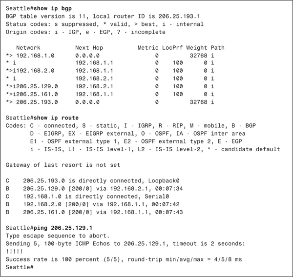
The moral of the story is that for IBGP to work correctly, one of two configuration options must be performed:
• The external routes must be redistributed into the IGP to ensure that the IGP can synchronize with BGP. The drawback to this approach is that if you are taking a large number of routes from BGP, such as a full Internet routing table, you are placing a huge processing and memory burden on the IGP routers. In the majority of cases, routers cannot handle this burden and will fail. In fact, several large-scale outages have resulted from full BGP routes being inadvertently redistributed into OSPF or IS-IS. In one incident, a major provider was down for 19 hours.
• The IBGP routers must be fully meshed, and synchronization must be disabled. Every router then has knowledge of the external routes via BGP, and disabling synchronization allows the routes to be entered into the routing table without having to first inform the IGP. The drawback to this approach is that in an AS where there are more than a few IBGP routers, peering every router with every other router becomes an administrative challenge. Nonetheless, this is the approach that is almost always used when dealing with Internet routes. Two tools for controlling the full IBGP mesh requirement, route reflectors and confederations, are presented in the next section.
Chapter 3 offers several examples of IBGP configurations. It also revisits the drawbacks to the two configuration options and demonstrates some partial solutions to them.
Managing Large-Scale BGP Peering
The preceding section pointed out that when an AS becomes large, attempting to create fully meshed IBGP peers can be daunting. This is just one of the problems that emerges when you attempt to work with BGP on a large scale. BGP features four tools that can simplify the management of large numbers of BGP peers:
• Peer groups
• Communities
• Route reflectors
• Confederations
The first two tools help simplify the management of routing policies between multiple peers, either internal or external. The second two tools simplify the management of IBGP among large numbers of peers.
Peer Groups
Often in large BGP internetworks, policies on a router apply to multiple peers. The same attributes might be set in the updates going to several peers, for example, or the same filter might be used on routes coming from several peers. In such cases, you can simplify configuration and management by adding peers that share common policies to a peer group.
A peer group is defined on a Cisco router with a name and a set of routing policies. Peers are then added to the peer group. Any changes that must be made to the policies can then be made for the group rather than for each individual peer. Peer groups also prove useful for improving performance on a router. Instead of repeatedly consulting the policy database for each update sent to each peer, the router can consult the policy database once, create a single update, and then send copies of it to all the peers in the group.
At times, additional policies might apply to one or more members of a peer group. In such a case, you can apply the additional policies to the appropriate neighbors in addition to the common policies of the group.
Communities
Whereas peer groups apply policies to a group of routers, communities apply policies to a group of routes. A router adds a route to a preconfigured community by setting its COMMUNITY attribute to some value that identifies it as a member of the community. Neighboring routers can then apply their policies, such as filtering or redistribution policies, to the routes based on the value of the COMMUNITY attribute. The COMMUNITY attribute, which can be set to a well-known value or to some value defined by the network administrator, is described more fully in the section "The COMMUNITY Attribute," earlier in this chapter.
You can set more than one COMMUNITY attribute for a single route. A router receiving a route with multiple COMMUNITY attributes has the option of setting policies based on all those attributes or on some subset of the attributes. When routes containing COMMUNITY attributes are aggregated, the aggregate inherits all the COMMUNITY attributes of all the routes.
Route Reflectors
Route reflectors are useful when an AS contains a large number of IBGP peers. (For more information, see RFC 1966 at www.isuedu/in-notes/rfc1771.txt.) Unless EBGP routes are redistributed into the autonomous system’s IGP, all IBGP peers must be fully meshed. For every n routers, there will be n(n – 1)/2 IBGP connections in the AS. For example, Figure 2-35 shows six fully meshed IBGP routers, hardly a large number of routers; even here, however, 15 IBGP connections are needed.

Figure 2-35 Fully Meshed IBGP Peers
Route reflectors offer an alternative to fully meshed IBGP peers. A router is configured as a route reflector (RR), and other IBGP routers, known as clients, peer with the RR only, rather than with every other IBGP router (see Figure 2-36). As a result, the number of peering sessions is reduced from n(n – 1)/2 to n – 1. A router reflector and its clients are known collectively as a cluster.
Figure 2-36 IBGP Clients in a Route Reflection Cluster Peer Only with the Route Reflector, Reducing the Number of Necessary IBGP Connections
Route reflectors work by relaxing the rule that IBGP peers cannot advertise routes learned from other IBGP peers. In the internetwork of Figure 2-36, for example, the route reflector learns routes from each of its clients. Unlike other IBGP routers, the RR can advertise these routes to its other clients and to nonclient peers. In other words, the routes from one IBGP client are reflected from the RR to the other clients. To avoid possible routing loops or other routing errors, the route reflector cannot change the attributes of the routes it receives from clients.
A client router in a route reflection cluster can peer with external neighbors, but the only internal neighbor it can peer with is a route reflector in its cluster or other clients in the cluster. However, the RR itself can peer with both internal and external neighbors outside of the cluster and can reflect their routes to its clients (see Figure 2-37).
Figure 2-37 Route Reflection Cluster Peering Relationships
If an RR receives multiple routes to the same destination, it uses the normal BGP decision process to select the best path. RFC 1966 defines three rules that the RR uses to determine who the route is advertised to, depending on how the route was learned:
• If the route was learned from a nonclient IBGP peer, it is reflected to clients only.
• If the route was learned from a client, it is reflected to all nonclients and clients, except for the originating client.
• If the route was learned from an EBGP peer, it is reflected to all clients and nonclients.
The route reflector functionality has to be supported only on the route reflector itself. From the clients’ perspectives, they are merely peering with an internal neighbor. This is an attractive feature of route reflectors, because routers with relatively basic BGP implementations can still be clients in a route reflection cluster.
The concept of route reflectors is similar to that of route servers, discussed earlier in this chapter. The primary purpose of both devices is to reduce the number of required peering sessions by providing a single peering point for multiple neighbors. The neighbors then depend on the one device to learn their routes. The difference between route reflectors and route servers is that route reflectors are also routers, whereas route servers are not.
A single RR, like a single route server, introduces a single point of failure into a system. If the RR fails, the clients lose their only source of NLRI. Therefore, for redundancy, a cluster can have more than one RR (see Figure 2-38). The clients have physical connections to each of the route reflectors, and they peer to each. If one of the RRs fails, the clients still have a connection to the other RR and do not lose reachability information.
Figure 2-38 A Cluster Can Have Multiple Route Reflectors for Redundancy
Note
Although it is possible for a client to have a physical link to only one RR and still peer to multiple RRs, this setup defeats the purpose of having redundancy. The client is still vulnerable to the failure of the single RR to which it is physically connected.
An AS also can have multiple clusters. Figure 2-39 shows an AS with two clusters. Each cluster has redundant route reflectors, and the clusters themselves are interconnected redundantly.

Figure 2-39 Multiple Route Reflection Clusters Can Be Created Within a Single Autonomous System
Because clients do not know they are clients, a route reflector can itself be a client of another route reflector. As a result, you can build "nested" route reflection clusters (see Figure 2-40).
Figure 2-40 A Route Reflector Can Be the Client of Another Route Reflector
Although clients cannot peer with routers outside of their own cluster, they can peer with each other. As a result, a route reflection cluster can be fully meshed (see Figure 2-41). When the clients are fully meshed, the route reflector is configured so that it does not reflect routes from one client to another. Instead, it reflects only routes from clients to its nonclient peers, and routes from nonclient peers to clients.
Figure 2-41 A Route Reflection Cluster Can Be Fully Meshed
Recall from the discussion in the section "IBGP and IGP Synchronization" that BGP cannot forward a route learned from one internal peer to another internal peer, because the AS_PATH attribute does not change within an AS, and routing loops could result. Note, however, that a route reflector is a BGP router in which this rule has been relaxed. To prevent routing loops, route reflectors use two BGP path attributes: ORIGINATOR_ID and CLUSTER_LIST.
ORIGINATOR_ID is an optional, nontransitive attribute that is created by the route reflector. The ORIGINATOR_ID is the router ID of the originator of a route within the local AS. A route reflector does not advertise a route back to the originator of the route; nonetheless, if the originator receives an update with its own RID, the update is ignored.
Each cluster within an AS must be identified with a unique 4-octet cluster ID. If the cluster contains a single route reflector, the cluster ID is the router ID of the route reflector. If the cluster contains multiple route reflectors, each RR must be manually configured with a cluster ID.
CLUSTER_LIST is an optional, nontransitive attribute that tracks cluster IDs the same way that the AS_PATH attribute tracks AS numbers. When an RR reflects a route from a client to a nonclient, it appends its cluster ID to the CLUSTER_LIST. If the CLUSTER_LIST is empty, the RR creates one. When an RR receives an update, it checks the CLUSTER_LIST. If it sees its own cluster ID in the list, it knows that a routing loop has occurred and ignores the update.
Confederations
Confederations are another way to control large numbers of IBGP peers. A confederation is an AS that has been subdivided into a group of subautonomous systems, known as member autonomous systems (see Figure 2-42). The BGP speakers within the confederation speak IBGP to peers in the same member AS and EBGP to peers in other member autonomous systems. The confederation is assigned a confederation ID, which is represented to peers outside of the confederation as the AS number of the entire confederation. External peers do not see the internal structure of the confederation; rather, they see a single AS. In Figure 2-42, AS 9184 is the confederation ID.

Figure 2-42 A Typical Confederation
You are very familiar with the concept of subdividing entities for better manageability. IP subnets are subdivisions of IP networks, and VLSM subdivides subnets. Similarly, autonomous systems are subdivisions of large internetworks (such as the Internet). Confederations are subdivisions of autonomous systems.
The section "AS_SET" described two types of AS_PATH attributes: AS_SEQUENCE and AS_SET. Confederations add two more types to the AS_PATH:
• AS_CONFED_SEQUENCE—This is an ordered list of AS numbers along a path to a destination. It is used in exactly the same way as the AS_SEQUENCE, except that the AS numbers in the list belong to autonomous systems within the local confederation.
• AS_CONFED_SET—This is an unordered list of AS numbers along a path to a destination. It is used in exactly the same way as the AS_SET, except that the AS numbers in the list belong to autonomous systems within the local confederation.
Because the AS_PATH attribute is used in updates between the member autonomous systems, loop avoidance is preserved. From the perspective of a BGP router within a member AS, all peers in other member autonomous systems are external neighbors.
When an update is sent to a peer external to the confederation, the AS_CONFED_SEQUENCE and AS_CONFED_SET information is stripped from the AS_PATH attribute, and the confederation ID is prepended to the AS_PATH. Because of this, external peers see the confederation as a single AS rather than as a collection of autonomous systems. As Figure 2-42 shows, it is common practice to use AS numbers from the reserved range 64512 to 65535 to number the member autonomous systems within a confederation.
When choosing a route, the BGP decision process remains the same, with one addition: EBGP routes external to the confederation are preferred over EBGP routes to member autonomous systems, which are preferred over IBGP routes. Another difference between confederations and standard autonomous systems is the way in which some attributes are handled. Attributes such as NEXT_HOP and MED can be advertised unchanged to EBGP peers in another member AS within the confederation, and the LOCAL_PREF attribute also can be sent.
Unlike route reflector environments in which only the route reflector itself has to support route reflection, all routers within a confederation must support the confederation functionality. This support is necessary because all routers must be able to recognize the AS_CONFED_SEQUENCE and AS_CONFED_SET types in the AS_PATH attribute. Because these AS_PATH types are removed from routes advertised out of the confederation, however, routers in other autonomous systems do not have to support confederations.
In very large autonomous systems, you can use confederations and route reflectors together. You can configure one or more RR clusters within one or more member autonomous systems for even more optimal control of IBGP peers.
BGP Message Formats
BGP messages are carried within TCP segments using TCP port 179. The maximum message size is 4096 octets, and the minimum size is 19 octets. All BGP messages have a common header (see Figure 2-43). Depending on the message type, a data portion might or might not follow the header.

Figure 2-43 The BGP Message Header
Marker is a 16-octet field that is used to detect loss of synchronization between BGP peers and to authenticate messages when authentication is supported. If the message type is Open or if the Open message contains no authentication information, the Marker field is set to all 1s. Otherwise, the value of the marker can be predicted by some computation as part of the authentication process.
Length is a 0-octet field that indicates the total length of the message, including the header, in octets.
Type is a 0-octet field specifying the message type. Table 2-6 indicates the possible type codes.
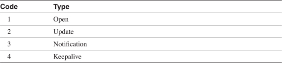
The Open Message
The Open message, whose format is shown in Figure 2-44, is the first message sent after a TCP connection has been established. If a received Open message is acceptable, a Keepalive message is sent to confirm the Open. After the Open has been confirmed, the BGP connection is in the Established state and Update, Keepalive, and Notification messages can be sent.

Figure 2-44 The BGP Open Message Format
The BGP Open message contains the following fields:
• Version—A 1-octet field specifying the BGP version running on the originator.
• My Autonomous System—A 2-octet field specifying the AS number of the originator.
• Hold Time—A 2-octet number indicating the number of seconds the sender proposes for the hold time. A receiver compares the value of the Hold Time field and the value of its configured hold time and accepts the smaller value or rejects the connection. The hold time must be either 0 or at least 3 seconds.
• BGP Identifier—The router ID of the originator. A Cisco router sets its router ID as either the highest IP address of any of its loopback interfaces or, if no loopback interface is configured, the highest IP address of any of its physical interfaces.
• Optional Parameters Length—A 1-octet field indicating the total length of the following Optional Parameters field, in octets. If the value of this field is zero, no Optional Parameters field in included in the message.
• Optional Parameters—A variable-length field containing a list of optional parameters. Each parameter is specified by a 1-octet type field, a 1-octet length field, and a variable-length field containing the parameter value.
The Update Message
The Update message, whose format is shown in Figure 2-45, is used to advertise a single feasible route to a peer, or to withdraw multiple unfeasible routes, or both.

Figure 2-45 The BGP Update Message Format
The BGP Update message contains the following fields:
• Unfeasible Routes Length—A 2-octet field indicating the total length of the following Withdrawn Routes field, in octets. A value of zero indicates that no routes are being withdrawn and that no Withdrawn Routes field is included in the message.
• Withdrawn Routes—A variable-length field containing a list of routes to be withdrawn from service. Each route in the list is described with a (Length, Prefix) tuple in which the Length is the length of the prefix and the Prefix is the IP address prefix of the withdrawn route. If the Length part of the tuple is zero, the Prefix matches all routes.
• Total Path Attribute Length—A 2-octet field indicating the total length of the following Path Attribute field, in octets. A value of zero indicates that attributes and NLRI are not included in this message.
• Path Attributes—A variable-length field listing the attributes associated with the NLRI in the following field. Each path attribute is a variable-length triple of (Attribute Type, Attribute Length, Attribute Value). The Attribute Type part of the triple is a 2-octet field consisting of four flag bits, four unused bits, and an Attribute Type code (see Figure 2-46).

Figure 2-46 The Attribute Type Part of the Path Attributes Field
• Network Layer Reachability Information—A variable-length field containing a list of (Length, Prefix) tuples. The Length indicates the length in bits of the following prefix, and the Prefix is the IP address prefix of the NLRI. A Length value of zero indicates a prefix that matches all IP addresses.
Table 2-7 shows the most common Attribute Type codes and the possible Attribute Values for each Attribute Type.
Table 2-7 Attribute Types and Associated Attribute Values*

The Keepalive Message
Keepalive messages are exchanged on a period one-third the hold time, but not less than 1 second. If the negotiated hold time is 0, Keepalives are not sent.
The Keepalive message consists of only the 19-octet BGP message header, with no additional data.
The Notification Message
Notification messages, whose format is shown in Figure 2-47, are sent when an error condition is detected. The BGP connection is closed immediately after the message is sent.

Figure 2-47 The BGP Notification Message Format
The BGP Notification message contains the following fields:
• Error Code—A 1-octet field indicating the type of error.
• Error Subcode—A 1-octet field providing more-specific information about the error. Table 2-8 shows the possible error codes and associated error subcodes.
• Data—A variable-length field used to diagnose the reason for the error. The contents of the Data field depend on the error code and subcode.
Table 2-8 BGP Notification Message Error Codes and Error Subcodes
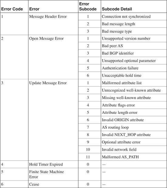
End Notes
1K. Lougheed and Y. Rekhter, "RFC 1105: A Border Gateway Protocol (BGP)" (Work in Progress)
2K. Lougheed and Y. Rekhter, "RFC 1163: A Border Gateway Protocol (BGP)" (Work in Progress)
3K. Lougheed and Y. Rekhter, "RFC 1267: A Border Gateway Protocol 3 (BGP-3)" (Work in Progress)
4Y. Rekhter and T. Li, "RFC 1771: A Border Gateway Protocol 4 (BGP-4)" (Work in Progress)
5Internet Engineering Steering Group, R. Hinden, Editor, "RFC 1517: Applicability Statement for the Implementation of Classless Inter-Domain Routing (CIDR)" (Work in Progress)
6V. Fuller et al., "RFC 1519: Classless Inter-Domain Routing (CIDR): An Address Assignment and Aggregation Strategy" (Work in Progress)
7Y. Rekhter and C. Topolcic, "RFC 1520: Exchanging Routing Information Across Provider Boundaries in the CIDR Environment" (Work in Progress)
8R. Chandra and P. Traina, "RFC 1997: BGP Communities Attribute" (Work in Progress)
Looking Ahead
Now that you have had a good look at the basics of BGP and related concepts, Chapter 3 shows you how to configure and troubleshoot BGP on Cisco routers. In addition to configuring BGP, you learn how to set routing policies and how to redistribute BGP and IGPs.
Recommended Reading
Halabi, B., and D. McPherson, Internet Routing Architectures, Second Edition. Indianapolis, Indiana: Cisco Press; 2000.
This book is considered by many as the definitive text on BGP-4.
Stewart J.W. III. BGP4: Inter-Domain Routing in the Internet. Reading, Massachusetts: Addison Wesley Longman; 1999.
Although not Cisco-specific, Stewart’s book is a handy, concise overview of BGP.
Review Questions
1 What is the most important difference between BGP-4 and earlier versions of BGP?
___________________________________________________________________________
___________________________________________________________________________
___________________________________________________________________________
2 What two problems was CIDR developed to alleviate?
___________________________________________________________________________
___________________________________________________________________________
___________________________________________________________________________
3 What is the difference between classful and classless IP routers?
___________________________________________________________________________
___________________________________________________________________________
___________________________________________________________________________
4 What is the difference between classful and classless IP routing protocols?
___________________________________________________________________________
___________________________________________________________________________
___________________________________________________________________________
5 Given the addresses 172.17.208.0/23, 172.17.210.0/23, 172.17.212.0/23, and 172.17.214.0/23, summarize the addresses with a single aggregate, using the longest possible address mask.
___________________________________________________________________________
___________________________________________________________________________
___________________________________________________________________________
6 What is an address prefix?
___________________________________________________________________________
___________________________________________________________________________
___________________________________________________________________________
7 The routing table in Example 2-16 is taken from a classless router. To what next-hop address does the router forward packets with each of the following destination addresses?
172.20.3.5
172.20.1.67
172.21.255.254
172.16.0.224
172.16.51.50
172.17.40.1
172.17.41.1
172.30.1.1
Example 2-16 The Routing Table for Review Question 7
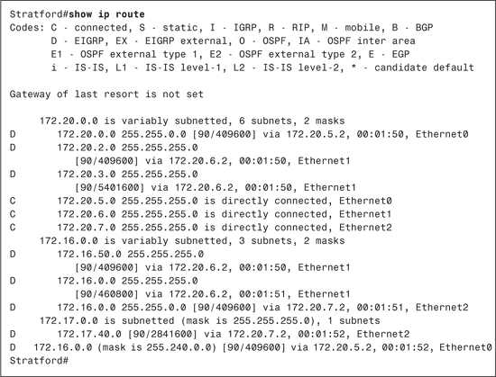
8 Explain how summarization helps hide network instabilities.
___________________________________________________________________________
___________________________________________________________________________
___________________________________________________________________________
9 Explain how summarization can cause asymmetric traffic patterns.
___________________________________________________________________________
___________________________________________________________________________
___________________________________________________________________________
10 Is asymmetric traffic undesirable?
___________________________________________________________________________
___________________________________________________________________________
___________________________________________________________________________
11 What is a NAP?
___________________________________________________________________________
___________________________________________________________________________
___________________________________________________________________________
12 What is a route server?
___________________________________________________________________________
___________________________________________________________________________
___________________________________________________________________________
13 What is a provider-independent address space, and why can it be advantageous to have one?
___________________________________________________________________________
___________________________________________________________________________
___________________________________________________________________________
14 Why can it be a problem to have a /21 provider-independent address space?
___________________________________________________________________________
___________________________________________________________________________
___________________________________________________________________________
15 What is a routing policy?
___________________________________________________________________________
___________________________________________________________________________
___________________________________________________________________________
16 What is the underlying protocol that BGP uses to reliably connect to its neighbors?
___________________________________________________________________________
___________________________________________________________________________
___________________________________________________________________________
17 What are the four BGP message types, and how is each one used?
___________________________________________________________________________
___________________________________________________________________________
___________________________________________________________________________
18 In what state or states can BGP peers exchange Update messages?
___________________________________________________________________________
___________________________________________________________________________
___________________________________________________________________________
19 What is NLRI?
___________________________________________________________________________
___________________________________________________________________________
___________________________________________________________________________
20 What is a path attribute?
___________________________________________________________________________
___________________________________________________________________________
___________________________________________________________________________
21 What are the four categories of BGP path attributes?
___________________________________________________________________________
___________________________________________________________________________
___________________________________________________________________________
22 What is the purpose of the AS_PATH attribute?
___________________________________________________________________________
___________________________________________________________________________
___________________________________________________________________________
23 What are the different types of AS_PATH?
___________________________________________________________________________
___________________________________________________________________________
___________________________________________________________________________
24 What is the purpose of the NEXT_HOP attribute?
___________________________________________________________________________
___________________________________________________________________________
___________________________________________________________________________
25 What is the purpose of the LOCAL_PREF attribute?
___________________________________________________________________________
___________________________________________________________________________
___________________________________________________________________________
26 What is the purpose of the MULTI_EXIT_DISC attribute?
___________________________________________________________________________
___________________________________________________________________________
___________________________________________________________________________
27 What attribute or attributes are useful if a BGP speaker originates an aggregate route?
___________________________________________________________________________
___________________________________________________________________________
___________________________________________________________________________
28 What is a BGP administrative weight?
___________________________________________________________________________
___________________________________________________________________________
___________________________________________________________________________
29 Given an EBGP route and an IBGP route to the same destination, which route will a BGP router prefer?
___________________________________________________________________________
___________________________________________________________________________
___________________________________________________________________________
30 A router has two IBGP routes to the same destination. Path A has a LOCAL_PREF of 300 and three AS numbers in the AS_PATH. Path B has a LOCAL_PREF of 200 and two AS numbers in the AS_PATH. Assuming no other differences, which path will the router choose?
___________________________________________________________________________
___________________________________________________________________________
___________________________________________________________________________
31 What is route dampening?
___________________________________________________________________________
___________________________________________________________________________
___________________________________________________________________________
32 Define the penalty, suppress limit, reuse limit, and half-life as they apply to route dampening.
___________________________________________________________________________
___________________________________________________________________________
___________________________________________________________________________
33 What is IGP synchronization, and why is it important?
___________________________________________________________________________
___________________________________________________________________________
___________________________________________________________________________
34 Under what circumstances can you safely disable IGP synchronization?
___________________________________________________________________________
___________________________________________________________________________
___________________________________________________________________________
35 What is a BGP peer group?
___________________________________________________________________________
___________________________________________________________________________
___________________________________________________________________________
36 What is a BGP community?
___________________________________________________________________________
___________________________________________________________________________
___________________________________________________________________________
37 What is a route reflector? What is a route reflection client? What is a route reflection cluster?
___________________________________________________________________________
___________________________________________________________________________
___________________________________________________________________________
38 What is the purpose of the ORIGINATOR_ID and the CLUSTER_LIST path attributes?
___________________________________________________________________________
___________________________________________________________________________
___________________________________________________________________________
39 What is a BGP confederation?
___________________________________________________________________________
___________________________________________________________________________
___________________________________________________________________________
40 Can route reflectors be used within confederations?
___________________________________________________________________________
___________________________________________________________________________
___________________________________________________________________________
41 What is the purpose of the next-hop-self function? Are there any reasonable alternatives to using this function?
___________________________________________________________________________
___________________________________________________________________________
___________________________________________________________________________