Chapter 5. Introduction to IP Multicast Routing
• Requirements for IP Multicast—This section explains the basic concepts of IP multicasting and examines the functions necessary for efficient multicasting, such as addressing and signaling.
• Multicast Routing Issues—This section describes the issues common to all IP multicast routing protocols.
• Operation of the Distance Vector Multicast Routing Protocol (DVMRP)—This section describes the operation of DVMRP.
• Operation of Multicast OSPF (MOSPF)—This section describes the operation of MOSPF.
• Operation of Core-Based Trees (CBT)—This section describes the operation of CBT.
• Introduction to Protocol Independent Multicast (PIM)—This section examines the basic PIM functions shared by both PIM-DM and PIM-SM.
• Operation of Protocol Independent Multicast, Dense Mode (PIM-DM)—This section describes the operation of PIM-DM.
• Operation of Protocol Independent Multicast, Sparse Mode (PIM-SM)—This section describes the operation of PIM-SM.
Multicasting is the process of sending data to a group of receivers. It might be argued that unicasting and broadcasting are subsets of multicasting. In the case of unicasting, there is only a single member of the group; in the case of broadcasting, all possible receivers are members of the group. This chapter demonstrates why such an argument is valid only on a conceptual level; in networking, at least, distinct differences exist between multicasting, unicasting, and broadcasting.
The delivery of radio and television programming is commonly called "broadcasting," but in reality it is multicasting. A transmitter sends data on a certain frequency, and some group of receivers acquires the data by tuning in to that frequency. The frequency is, in this sense, a multicast address. All receivers within the range of the transmission are capable of receiving the signal, but only those who listen to the correct frequency actually receive it.
The signal range brings up another important concept: Radio and television transmissions have scope—they are limited by the power of the transmitter. Receivers outside the scope of the transmission cannot receive the signal. You will see in this chapter that IP multicast networks also can have scope.
You have already had some exposure to IP multicasting in Volume I. RIP-2, EIGRP, and OSPF all employ multicasting for efficiency in communicating routing information. Applications can use multicasting for exactly the same reason—to increase network efficiency and conserve network resources. Figure 5-1 depicts a set of IP hosts. One of the hosts is a source (S) of data that must be delivered to a group (G) of receivers. There is more than one receiver, but the group does not contain all possible receivers.

Figure 5-1 The Source Must Deliver the Same Data to Multiple Receivers
One approach is for the source to use a replicated unicast. That is, the source creates a separate packet containing identical data for each destination host in the group. Each packet is then unicast to a specific host, as shown in Figure 5-2.

Figure 5-2 Unicasting the Same Data to Multiple Receivers Places a Burden on the Source
If there are only a few destinations, this scheme works fine. In fact, many "multicast" applications in use today actually utilize replicated unicast. As the number of recipients grows into the hundreds or thousands, however, the burden on the host to create and send so many copies of the same data also increases. More importantly, the host’s interface, directly connected medium, directly connected router, and slow WAN links all become potential bottlenecks. There are also problems if the data is delay-sensitive and cannot be contained in a single packet. If all the copies of packet number 2 must wait for all the copies of packet number 1 to be queued and sent, the queuing delay can introduce unacceptable gaps in the data stream.
Another possible approach to multicasting is to broadcast the data as depicted in Figure 5-3. This removes the burden from the source and its local facilities, which now have to send only a single copy of each packet, but it can extend the burden to the other hosts in the network. Each host must accept a copy of the broadcasted packet and process the packet. It is only at the higher layers, or possibly within the application itself, that disinterested hosts recognize that the packet is to be discarded. If the number of hosts in the receiving group is small in relation to the total number of hosts in the network, this processing burden can again be unacceptable.

Figure 5-3 Broadcasting Data Can Place a Burden on the Rest of the Network
Note
When there are relatively few group members in relation to the total number of hosts in a multicast domain, the domain is sparsely populated. You will encounter this concept again later in this chapter.
Another difficulty with broadcasting is that IP routers do not forward packets to broadcast destinations. If the cloud in Figure 5-3 is a routed internetwork rather than a single broadcast medium, broadcast packets cannot reach the remote hosts. Directed broadcasts could be used, but that may be the worst possible solution. Not only would all hosts receive the packet, but also the source would again be burdened with having to replicate packets.
Multicasting allows the source to send a single packet to a single multicast destination address, thus removing the processing burden of replicating packets. Any receiver that is listening for the multicast address can receive the packet, removing the need for disinterested hosts to process an unwanted packet. And unlike broadcast packets, multicast-aware routers can forward multicast packets.
Many aspects of IP multicasting are not covered in this chapter. This book is concerned only with IP routing, so the primary focus of this chapter is on IP multicast routing. Other topics are touched upon only as they pertain to routing. For a complete treatment of IP multicast, have a look at the references cited at the end of the chapter in "Recommended Reading."
Requirements for IP Multicast
IP multicast is not a new concept; Steve Deering wrote the first RFC on multicast host requirements in 1986.1 But it is only in the past few years that interest in multicasting has really taken off, as enterprises present increasing demands for one-to-many and many-to-many communications.
Examples of one-to-many applications include video and audio feeds for distance learning or company news, software distribution, network-based entertainment programs, news and stock updates, and database or Web site replication. The classic many-to-many application is conferencing, including video, audio, and shared whiteboards. Multiplayer games are another many-to-many application, although most corporations would be loath to include them on a wish list. As the use of such group-based applications increases, the efficiency and performance advantages of multicast over broadcast and replicated unicast for packet delivery become more attractive.
You must make a variety of protocol choices when implementing IP multicast. Because of this, multicast is presently found primarily in enterprise networks where a single administrative authority can make the design choices. As the popularity of multicasting grows, however, customers are increasing their pressure on ISPs to support multicast across the Internet. Interest in multicast within ISPs is also growing as more and more replicated unicast traffic is sent across the Internet, eating up more and more bandwidth. Although corporations have been interested in multicast for some time, the "killer app" that will finally bring IP multicast to maturity will be entertainment over the Internet.
Multicast has been researched for some time on a subset of the Internet known as the Multicast Backbone, or MBone. ISPs are also beginning to offer multicast services to their customers, such as UUNET’s UUcast. However, ubiquitous availability of multicast services across the entire Internet must await further research and development of inter-AS protocols such as Multiprotocol BGP (MBGP) and Border Gateway Multicast Protocol (BGMP). Presently, no IP multicast routing protocols exist that support routing policies comparable to those supported by BGP. Until adequate tools for enforcing policy are introduced, it is unlikely that multicasting will find wide Internet acceptance.
The three basic requirements for supporting multicast across a routed internetwork are as follows:
• There must be a set of addresses by which multicast groups are identified.
• There must be a mechanism by which hosts can join and leave groups.
• There must be a routing protocol that allows routers to efficiently deliver multicast traffic to group members without overtaxing network resources.
This section examines the basics of each of these requirements; subsequent sections examine the details of the various protocols that are currently available to meet the requirements.
Multicast IP Addresses
The IANA has set aside Class D IP addresses for use as multicast addresses. According to the first octet rule, as described in Chapter 2, "TCP/IP Review," of Volume I, the first four bits of a Class D address are always 1110, as shown in Figure 5-4. Finding the minimum and maximum 32-bit numbers within this constraint, the range of Class D addresses is 224.0.0.0–239.255.255.255.

Figure 5-4 Class D Addresses Are in the Range 224.0.0.0–239.255.255.255
Unlike the Class A, B, and C address ranges, the Class D range is "flat"—that is, subnetting is not used, as demonstrated by Figure 5-5. Therefore, with 28 variable bits, 228 (more than 268 million) multicast groups can be addressed out of the Class D space.

Figure 5-5 Unlike Class A, B, and C IP Addresses, Class D Addresses Do Not Have a Network Portion and a Host Portion
A multicast group is defined by its multicast IP address; groups may be permanent or transient. Permanent refers to the fact that the group has a permanently assigned address, not that members are permanently assigned to the group. In fact, hosts are free to join or leave any group. Transient groups are, as you might guess, groups that do not have a permanent existence—like a videoconference group. An unreserved address is assigned to the group and is relinquished when the group ceases to exist.
Table 5-1 shows some of the well-known addresses assigned to permanent groups by the IANA. You have encountered most of these addresses before, when you studied the routing protocols to which they are assigned. For example, you know that on a multiaccess network, OSPF DRothers send updates to the OSPF DR and BDR at 224.0.0.6; the DR sends packets to the DRothers at 224.0.0.5.
Table 5-1 Some Well-Known Reserved Multicast Addresses

The IANA reserves all the addresses in the range 224.0.0.0–224.0.0.255 for routing protocols and other network maintenance functions. Multicast routers do not forward packets with a destination address from this range. There are also addresses outside of this range that are reserved for open and commercial groups; for example, 224.0.1.1 is reserved for the Network Time Protocol (NTP), 224.0.1.8 is assigned to SUN NIS+, and 224.0.6.0–224.0.6.127 are assigned to the Cornell ISIS Project. Yet another reserved range is 239.0.0.0–239.255.255.255. The use of this last group of addresses is discussed in the section "Multicast Scoping" later in this chapter. For a complete list of reserved Class D addresses, see Appendix C, "Reserved Multicast Addresses," or RFC 1700.
A group member’s network interface card (NIC) also must be multicast-aware. When a host joins a group, the NIC determines a predictable MAC address. To accomplish this, all multicast-aware Ethernet, Token Ring, and FDDI NICs use the reserved IEEE 802 address 0100.5E00.0000 to determine a unique multicast MAC. It is significant that the eighth bit of this address is 1; that bit, in the 802 format, is the Individual/Group (I/G) bit. When set, it indicates that the address is a multicast address.
Multicasting Over Ethernet and FDDI
Ethernet and FDDI interfaces map the lower 23 bits of the group IP address onto the lower 23 bits of the reserved MAC address to form a multicast MAC address, as shown in Figure 5-6. Here, the Class D IP address 235.147.18.23 is used to create the MAC address 0100.5E13.1217.

Figure 5-6 Multicast MAC Addresses on Ethernet and FDDI Networks Are Created by Concatenating the Last 23 Bits of the IP Address with the First 25 Bits of the MAC Address 0100.5E00.0000
You already have encountered a couple of these addresses. Recall that in Chapter 9, "Open Shortest Path First," of Volume I, it was briefly explained that the All OSPF Routers address 224.0.0.5 uses a MAC address of 0100.5E00.0005, and the All OSPF Designated Routers address 224.0.0.6 uses the MAC address 0100.5E00.0006. Now you know why.
Because only the last 23 bits of the IP address are mapped to the MAC address, the resulting multicast MAC address is not universally unique. For example, the IP address 225.19.18.23 will produce the very same MAC address, 0100.5E13.1217, as 235.147.18.23. In fact, calculating the ratio of the total number of Class D addresses (228) to the number of possible MAC addresses under the reserved prefix (223) reveals that 32 different Class D IP addresses can be mapped to every possible MAC address!
The IETF’s position is that the odds of two or more group addresses existing on the same LAN producing the same MAC address are acceptably remote. On the rare occasion that such a conflict does arise, the members of the two groups on the LAN will receive each other’s traffic. In most of these cases, each group’s packets will be destined for different port numbers or possibly have different application layer authentication schemes; each group’s members will discard the other group’s packets at the transport layer or above.
The benefits of this predictable MAC approach are twofold:
• A multicast source or router on the local network has to deliver only a single frame to the multicast MAC address in order for all group members on the LAN to receive it.
• Because the MAC address is always known if the group address is known, there is no need for an ARP process.
Multicasting Over Token Ring
Multicast over Token Ring networks is treated differently. Token Ring specifies functional or function-dependent MAC addresses to reach stations running such common TR functions as Active Monitor, Ring Parameter Server, and Ring Error Monitor. The first bit of the first octet of the TR MAC address is the I/G address, which indicates whether the address is unicast (I/G=0) or broadcast/multicast (I/G=1). The second bit is the Universal/Local (U/L) bit, which indicates whether the address is a manufacturer burned-in address (U/L=0) or a locally administered address (U/L=1). Additionally, the first bit of the third octet is the Functional Address Indicator (FAI). The job of the FAI is to distinguish functional addresses (I/G=1, U/L=1, FAI=0) from locally administered group address (I/G=1, U/L=1, FAI=1). A specific functional address is created by setting one, and only one, of the 31 remaining bits after the FAI. So, for example, the functional address of the Active Monitor is C000.0000.0001 and a bridge is reached at C000.0000.0100. Because only one of the 31 bits can be set, there are 31 available functional addresses. This rule has consequences for IP multicast.
Token Ring MAC addresses use the little-endian format, in which each octet is read from right to left; Ethernet uses the big-endian format, in which each octet is read from left to right. Therefore, the Ethernet multicast MAC address of 0100.5E13.1217 would be read by Token Ring as 8000.7AC8.48E6. The FAI in this TR address is 0, but more than one of the following 31 bits is set to 1. Therefore, Token Ring interprets the address as an illegal functional address.
Note
FDDI also uses the little-endian format, but it does not use functional addresses such as Token Ring and therefore supports the same mapping scheme as Ethernet.
Because IP addresses cannot be mapped into Token Ring addresses as they are into Ethernet addresses, another method must be found to resolve this issue. Currently, there are two methods for addressing TR frames carrying IP multicast packets:2
• Just use the broadcast address FFFF.FFFF.FFFF for all frames carrying multicast packets.
• Use a single reserved functional address, C000.0004.0000.
Cisco routers default to the first method and support the second method with the command ip multicast use-functional configured on TR interfaces.
Both of these methods have drawbacks. The first method is inefficient, delivering multicast packets to all stations on the ring and relying on upper-layer protocols to accept or reject the packets. The second method can be used only if the TR NICs on all stations on the ring recognize the functional address. Not all NICs do. Another problem with the second method is that TR NICs that recognize a functional address send an interrupt to the station’s CPU. If there is even moderate IP multicast traffic on the ring, and especially if there is multicast traffic for several different groups all mapped to the one functional address, host performance will suffer. Because of these limitations, Token Ring is a poor choice for supporting IP multicast.
Group Membership Concepts
Before a host can join a group, it (or its user) must know what groups are available to be joined, and how to join them. Various mechanisms are available for advertising multicast groups, such as online "TV Guides," or Web-based schedules such as the one shown in Figure 5-7.
Figure 5-7 One Way of Locating Multicast Groups Is Through Web-Based Announcements, Such as This Schedule of MBone Sessions at www.cilea.it/MBone/browse.htm
There are also tools that utilize such protocols as Session Description Protocol (SDP) and Session Advertisement Protocol (SAP) to describe multicast events and advertise those descriptions. Figure 5-8 shows an example of an application that uses these protocols. A user also may learn of a multicast session by invitation, such as via a simple e-mail.

Figure 5-8 Applications Such as Multikit Listen for SDP and SAP and Display the Multicast Sessions Advertised by Those Protocols
A detailed discussion of these mechanisms is beyond the scope of this book. This section presumes that hosts have somehow learned of a multicast group, and it examines the issues around joining and leaving the group. After examining these issues, you will see how they are handled by the Internet Group Management Protocol (IGMP), the de facto protocol for managing IP multicast groups on individual subnets.
Joining and Leaving a Group
Interestingly, the source of a multicast session does not have to be a member of the multicast group to which it is sending traffic. In fact, the source typically does not even know what hosts, if any, are members of the group. Receivers are free to join and leave groups at any time. This again fits the earlier analogy of a radio or television signal; audience members can tune in or tune out at any time, and the originating station has no direct way of knowing who is listening.
If the source and all group members share a common LAN, no other protocols are required. The source sends packets to a multicast IP (and MAC) address, and the group members "tune in" to this address. But sending multicast traffic over a routed internetwork becomes more complicated. Every router could merely forward all multicast packets onto every LAN, in case there are group members on the LAN, but this partially circumvents the goal of multicasting, which is to conserve network resources. If no group members are on the LAN, bandwidth and processing is wasted not only on that subnet, but also on all data links and routers leading to it.
Therefore, a router must have some means to learn whether a connected network includes group members, and if so, members of what group. When a router becomes aware of a multicast session, it can query all of its attached subnets for hosts that want to join the receiving group. The query might be addressed to the "all systems on this subnet" address of 224.0.0.1, or it might be addressed to the specific address of the group for which it is querying. If one or more hosts respond, the router can then forward the session’s packets onto the appropriate subnet, as illustrated in Figure 5-9.


Figure 5-9 Multicast Group Member Discovery
The router can periodically resend queries to the subnet. If there are still group members on the subnet, they will respond to all queries to let the router know they are still active in the group. If no hosts respond, the router assumes that all hosts on the subnet have left the group, and it ceases forwarding the group’s packets onto the subnet.
Join Latency
A problem with the scheme described so far is that if a host knows of a group it wants to join, it is not always practical for the host to wait for a router to query for the group. To reduce this wait time, a host could send a message to the router requesting a join, without waiting for a query. Upon receiving the join request, the router immediately forwards the multicast traffic onto the subnet.
This procedure has benefits for more than just the local subnet. In the section "Multicast Routing Concepts" later in this chapter, you will see that having hosts initiate the join can help make multicast routing protocols more efficient. If a router has no group members on any of its attached subnets, and the subnets are not transit networks for multicast traffic to other routers, the router itself can request that upstream neighbors not forward multicast traffic to it. The result is that the traffic streams do not enter parts of the network in which there are no group members. If the router then receives a join request on one of its attached subnets, it can send a request upstream to begin receiving the relevant data stream.
The trade-off of this scheme is that if a host sends a join request to its local router, and then has to wait for the router to request the appropriate traffic from its upstream neighbors, the join latency is increased. Join latency is the period between the time a host sends a join request and the time the host actually begins receiving group traffic. Of course, if there are already other group members on the subnet when the host decides to join, the join latency will be practically zero. The host has no reason to send a join request to the router; it can just begin listening to the packets that are already being forwarded onto its subnet for the other group members.
Leave Latency
Allowing a host to explicitly notify its local router when it leaves a group can increase efficiency as well. Rather than having to wait for no hosts to respond to its queries before it implicitly concludes that there are no group members on a subnet, the router can actively determine whether there are remaining members. Upon receiving a leave notification from a host, the router immediately sends a query onto the subnet, asking whether there are any remaining members. If no one responds, the router concludes that there are no more members and can cease forwarding packets for the group onto that subnet. The result is a decreased leave latency, which is the period between the time the last group member on a subnet leaves the group and the time the router stops forwarding group traffic onto the subnet.
Host-initiated group leaves also improve routing protocol efficiency. If a router knows that it no longer has any group members on any of its subnets, it can "prune" itself from the multicast tree. The sooner a router determines that there are no group members, the sooner it can prune itself.
Decreased join and leave latencies also can improve the overall quality of a multicast network. There could be a large suite of multicast groups known to a host. Low join and leave latencies mean that the end user can easily "channel surf" through the available groups in the same way that users casually flip through radio and television channels.
Group Maintenance
The message that a host sends to a router to indicate that it wants to join a group is known as a report. A host can use several possible destination addresses when sending a report:
• The report can be unicast to the router that sent the query. The problem here is that there may be more than one router attached to the subnet that is tracking the group. All concerned routers must hear the report.
• The report can be sent to the "all routers on this subnet" address of 224.0.0.2. However, you will see shortly that it is useful for other group members on the subnet to also hear the report.
• To ensure that other group members hear the report, it can be sent to the "all systems on this subnet" address of 224.0.0.1. This method reduces the efficiency of multicasting, however, by forcing all multicast-capable hosts on the subnet, not just the group members, to process the report beyond Layer 2.
• The report can be sent to the group address. This method ensures that all group members on the subnet, and any routers listening for members of the group, hear the report. The NICs of hosts that are not members of the group reject the reports based on their Layer 2 address.
If all group members on a subnet respond to a query, bandwidth is unnecessarily wasted. After all, the router needs to know only that there is at least one member of the group on the subnet; it does not need to know exactly how many there are, or who they are. Another problem with all group members responding to a query is the possibility of collisions if all members respond at once. Backing off and retransmitting consumes more network and host resources. If many group members are on the subnet, there is an increased probability that multiple collisions will occur before everyone sends his report.
Sending reports to the group address eliminates multiple reports on a subnet. When a query is received, each group member starts a timer based on a random value. The member does not send a report until the timer expires. Because the timers are random, it is much more likely that one member’s timer will expire before the other timers. This member sends a report, and because the report is sent to the group address, all other members hear it. These other members, hearing the report, cancel their timers and do not send a report of their own.
As a result, only one report is generally sent on the subnet. One report per subnet is all the router needs.
Multiple Routers on a Network
The possibility was raised in the preceding section that multiple routers might be attached to a subnet, all of which need to know whether group members are present. Figure 5-10 shows an example. Two routers are attached to the subnet, both of which receive the same multicast stream from the same source over different routes. If one router or route fails, the group members can continue to receive their multicast session from the other router. Under normal circumstances, however, it is inefficient for both routers to forward the same data stream onto the subnet.

Figure 5-10 Two Routers Receive the Same Multicast Session, but Only One Forwards It onto the Subnet
The routers are aware of each other because of their routing protocols. So one way to ensure that only one router forwards the session onto the subnet is to add a designated router, or querier, function to the multicast routing protocol. The querier is responsible for forwarding the multicast stream. The other router or routers only listen, and they begin forwarding the stream only if the querier fails.
The problem with allowing the routing protocol to elect a querier is that multiple IP multicast routing protocols are available. If the two routers in Figure 5-10 are running incompatible protocols, their respective querier election processes will not detect each other; each will decide that it is the querier, and both will forward the data stream.
The local group management protocol, however, is independent of the routing protocols. The routers have to run this common protocol to query group members, so it makes sense to give the querier function to the group management protocol. This guarantees that the routers are speaking a common language on the subnet and can agree on which is responsible for forwarding the session.
Internet Group Management Protocol (IGMP)
Regardless of which of the several routing protocols is used in a multicast internetwork, IGMP is always the "language" spoken between hosts and routers. All hosts that want to join multicast groups, and all routers with interfaces on subnets containing multicast hosts, must implement IGMP. It is a control protocol like ICMP, sharing some functional similarities. Like ICMP, it is responsible for managing higher-level data exchanges. IGMP messages are encapsulated in IP headers like ICMP (with a protocol number of 2), but unlike ICMP, the messages are limited to the local data link. This is guaranteed both by the IGMP implementation rules, which require that a router never forward an IGMP message, and by always setting the TTL in the IP header to 1.
There are two current versions of IGMP: IGMPv1 is described in RFC 1112,3 and IGMPv2 is described in RFC 2236.4 Cisco IOS Software Release 11.1 and all later versions support IGMPv2 by default; however, many host TCP/IP implementations still support only version 1 (Windows NT 4.0 with service packs previous to SP4, for example). For this reason, the default can be changed with the ip igmp version command.
This next section discusses IGMPv2 and then presents its differences with IGMPv1. IGMPv3 has also been proposed,5 although IOS does not currently support it. However, version 3 is briefly discussed in this section with the expectation that Cisco IOS Software may support it in the near future.
IGMPv2 Host Functions
Hosts running IGMPv2 use three types of messages:
• Membership Report messages
• Version 1 Membership Report messages
• Leave Group messages
Membership Report messages are sent to indicate that a host wants to join a group. The messages are sent when a host first joins a group, and sometimes in response to a Membership Query from a local router.
When a host first learns of a group and wants to join, it does not wait for the local router to send a query. As you will learn in the sections on the various multicast routing protocols, the router may not—in fact, most likely does not—have any knowledge of the particular group the host wants to join, and therefore does not query for members. If the host had to wait for a query, it might never get the opportunity to join. Instead, when the host first joins a group, it sends an unsolicited Membership Report for the group.
Multicast sessions are identified in the routers by a (source, group) pair of addresses, where source is the address of the session’s originator and group is the Class D group address. If the local multicast router does not already have knowledge of the multicast session the host wants to join, it sends a request upstream toward the source. The data stream is received, and the router begins forwarding the stream onto the subnet of the host that requested membership.
The destination address of the Membership Report message’s IP header is the group address, and the message itself also contains the group address. To ensure that the local router receives the unsolicited Membership Report, the host sends one or two duplicate reports separated by a short interval. RFC 2236 recommends an interval of 10 seconds.
IGMPv2 hosts support IGMPv1 Membership Reports for backward compatibility. The mechanisms that IGMPv2 uses to detect and support IGMPv1 hosts and routers on its subnet are discussed in the section "IGMPv1 Versus IGMPv2."
The local router periodically polls the subnet with queries. Each query contains a value called the Max Response Time, which is normally 10 seconds (specified in units of tenths of a second). When a host receives a query, it sets a delay timer to a random value between 0 and the Max Response Time. If the timer expires, the host responds to the query with one Membership Report for each group to which it belongs.
Note
All multicast-enabled devices are members of the "all systems on this subnet" group, represented by the group address 224.0.0.1. Because this is a default, hosts do not send Membership Reports for this group.
Because the destination of the Membership Report is the group address, other group members that might be on the subnet hear the report in addition to the router. If the host receives a Membership Report for a group before its delay timer expires, it does not send a Membership Report for that group. In this way, the router is informed of the presence of at least one group member on the subnet, without all members flooding the subnet with reports.
When a host leaves a group, it notifies the local router with a Leave Group message. The message contains the address of the group being left, but unlike Membership Report messages, the Leave Group message is addressed to the "all routers on this subnet" address of 224.0.0.2. This is because only the multicast routers on the subnet need to know that the host is leaving; other group members do not.
RFC 2236 recommends that a Leave Group message be sent only if the leaving member was the last host to send a Membership Report in response to a query. As the next section explains, the local router always responds to a Leave Group message by querying for remaining group members. If group members other than the "last responder" leave quietly, the router continues forwarding the session and does not send a query. As a result, a little bandwidth is saved. However, this behavior is not required. If the designer of a multicast application does not want to include a state variable to remember whether this host was the last to respond to a query, the application can always send a Leave Group message when it leaves a group.
IGMPv2 Router Functions
The only type of IGMP message sent by routers is a query. Within IGMPv2, there are two subtypes of queries:
• General Query
• Group-Specific Query
The General Query is the message with which the router polls each of its subnets to discover whether group members are present and to detect when there are no members of a group left on a subnet. By default, the queries are sent every 60 seconds; the default can be changed to any value between 0 and 65,535 seconds with the command ip igmp query-interval.
As described in the preceding section, the query also contains a value called the Max Response Time. This value specifies the maximum amount of time the host has to respond to a query with a Membership Report. By default, the Max Response Time is 10 seconds; you can use the command ip igmp query-max-response-time to change it. The value is carried in the message in an 8-bit field and is expressed in units of tenths of a second (although the value is specified with ip igmp query-max-response-time in units of seconds). For example, the default 10 seconds is expressed within the message as 100 tenths of a second. Therefore, the range that can be specified is 0 to 255 tenths, or 0 to 25.5 seconds.
The General Query message is sent to the "all systems on this subnet" address of 224.0.0.1 and does not contain a reference to any specific group. As a result, the single message polls for reports from members of any and all groups that might be active on the subnet. The router tracks known groups and the interfaces attached to subnets with active members, as shown in the output in Example 5-1.
Example 5-1 The show ip igmp groups Command Displays the IP Multicast Groups of Which the Router Is Aware

If a Cisco multicast router does not hear a Membership Report on a particular subnet for a group within 3 times the query interval (3 minutes by default), the router declares that no active members of the group are on the subnet. This covers the eventuality of a lone group member being disconnected or otherwise not following the IGMPv2 rules for leaving a group.
This differs from RFC 2236, which specifies twice the query interval plus one Max Response Time interval.
The normal way that a host leaves a group is by sending a Leave Group message. When a router receives a Leave Group message, it must determine whether any remaining members of that group are on the subnet. To do this, the router issues a Group-Specific Query, which differs from a General Query in that it contains the group address, and it also uses the group address as its destination address.
If the Group-Specific Query were to become lost or corrupted, a remaining group member on the subnet might not send a report. As a result, the router would incorrectly conclude that there are no group members on the subnet and stop forwarding the session packets. To protect against this eventuality, the router sends two Group-Specific Queries, separated by a 1-second interval.
When a multicast-enabled router first becomes active on a subnet, it assumes that it is the querier—the router responsible for sending all General and Group-Specific Queries to the subnet—and immediately sends a General Query.
Note
RFC 2236 recommends sending multiple queries; however, Cisco’s IGMPv2 sends only one.
This action serves both to quickly discover the group members active on the subnet and to alert other multicast routers that may be on the subnet. When there are multiple routers, the rule for electing the querier is simple: The router with the lowest IP address is the querier. So when the existing router on the subnet hears the General Query from the new router, it checks the source address. If the address is lower than its own IP address, it relinquishes the role of querier to the new router. If its own IP address is lower, it continues sending queries. When the new router receives one of these queries, it sees that the old router has a lower IP address and becomes a nonquerier.
If the nonquerier does not hear queries from the querier within a certain period of time, known as the Other Querier Present Interval, it concludes that the querier is no longer present and assumes that role. Cisco IOS Software has a default Other Querier Present Interval of twice the Query Interval, or 120 seconds; you can change this with the command ip igmp query-timeout.
IGMPv1
The important differences between IGMPv1 and IGMPv2 are as follows:
• IGMPv1 has no Leave Group message, meaning that there is a longer period between the time the last host leaves a group and the time the router stops forwarding the group traffic.
• IGMPv1 has no Group-Specific Query. This follows from the fact that there is no Leave Group message.
• IGMPv1 does not specify a Max Response Time in its query messages. Instead, hosts have a fixed Max Response Time of 10 seconds.
• IGMPv1 has no querier election process. Instead, it relies on the IP multicast routing protocol to elect a designated router on the subnet. Because different protocols use different election mechanisms, it is possible under IGMPv1 to have more than one querier on a subnet.
The section "IGMP Message Format" illustrates how these differences affect the fields in IGMPv1 and IGMPv2 messages.
In some cases, IGMPv1 and IGMPv2 implementations might exist on the same subnet:
• Some group members might run IGMPv1 while others run IGMPv2.
• Some group members might run IGMPv2 while the router runs IGMPv1.
• The router might run IGMPv2 while some group members run IGMPv1.
• One router might run IGMPv1 while another router on the subnet runs IGMPv2.
RFC 2236 describes several mechanisms that allow IGMPv2 to adapt in these situations. If there is a mixture of version 1 and version 2 members on the same subnet, the version 2 members treat both version 1 and version 2 Membership Reports the same when determining whether to suppress their own Membership Reports. That is, if a version 2 member hears a query from the router and subsequently hears a version 1 Membership Report for its group before its own delay timer expires, it does not send a Membership Report. Version 1 hosts, on the other hand, ignore version 2 messages. Therefore, if a version 2 Membership Report is sent for a group first, the version 1 member also sends a report when its delay timer expires. This does not cause problems for the version 2 host, and this is important for the version 2 router so that it is aware of the presence of version 1 group members.
If a host is running version 2 and the local router is running version 1, the IGMPv1 router ignores the version 2 messages. So when a version 2 host receives a version 1 query, it responds with version 1 Membership Reports. The IGMPv1 query also does not specify a Max Response Time, so the IGMPv2 host uses the fixed version 1 period of 10 seconds. The host may or may not send Leave Group messages in the presence of version 1 routers; the IGMPv1 router does not recognize Leave Group messages, and ignores them.
If a version 2 router receives a version 1 Membership Report, it treats all members of the group as if they are running version 1. The router ignores Leave Group messages and hence does not send Group-Specific Queries that the version 1 members would ignore. Instead, it sets a timer, known as the Old Host Present Timer (as shown in Example 5-2). The period of the timer is the same value as the Group Membership Interval. Whenever a new version 1 Membership Report is received, the timer is reset; if the timer expires, the router concludes that no more version 1 members of the group are on the subnet and reverts to version 2 messages and procedures.
Note
As described earlier, the Group Membership Interval is the period of time that the router waits to hear a Membership Report before declaring that no members are on a subnet. Cisco’s default is three times the Query Interval.
Example 5-2 This Multicast Router Is Receiving IGMPv2 Membership Reports for Group 239.1.2.3 and IGMPv1 Membership Reports for Group 228.0.5.3. The Version 1 Reports Cause the Router to Set an Old Host Present Timer for That Group
Gold#debug ip igmp
IGMP debugging is on
Gold#
IGMP: Send v2 Query on Ethernet0/0 to 224.0.0.1
IGMP: Received v2 Report from 172.16.1.23 (Ethernet0/0) for 239.1.2.3
IGMP: Received v1 Report from 172.16.1.254 (Ethernet0/0) for 228.0.5.3
IGMP: Starting old host present timer for 228.0.5.3 on Ethernet0/0
IGMP: Send v2 Query on Ethernet0/0 to 224.0.0.1
IGMP: Received v2 Report from 172.16.1.23 (Ethernet0/0) for 239.1.2.3
IGMP: Received v1 Report from 172.16.1.254 (Ethernet0/0) for 228.0.5.3
IGMP: Starting old host present timer for 228.0.5.3 on Ethernet0/0
Notice in Example 5-2 that the router continues to send version 2 General Queries. The only significant difference between these queries and version 1 queries is that the Max Response Time is nonzero. The field in which this value is carried is unused in version 1, and the version 1 host ignores it. As a result, the host interprets version 2 queries as version 1 queries.
Another point of interest in Example 5-2 is that the Old Host Present timer is set only for group 228.0.5.3. The router treats only this group as an IGMPv1 group. Group 239.1.2.3, on the same interface, is treated as a version 2 group.
If version 1 and version 2 routers exist on the same subnet, the version 1 router will not participate in the querier election process. Because of this, it is important that the version 2 router behaves as a version 1 router for consistency. There is no automatic conversion to version 1; the version 2 router must be manually configured with the ip igmp version 1 command.
IGMPv3
Because IGMPv3 is still under development and is not yet supported, this section does not examine it in the detail that the first two versions are examined. Instead, this section summarizes the major features that this version will add if and when it comes into general use.
The primary addition to IGMPv3 is the inclusion of a Group-and-Source-Specific Query. This allows a group to be identified not only by group address, but also by source address. The Membership Report and Group Leave messages are modified so that they also can make this identification.
When a group has many sources (a many-to-many group), the IGMPv3 router can perform source filtering based on the requests of group members. For example, a particular member may want to receive group traffic from only certain specified sources, or it may want to receive traffic from all sources except certain specified sources. The member can express these wants in a Membership Report with Include or Exclude filter requests. If no member on a particular subnet wants to receive traffic from a particular source, the router does not forward that source’s traffic onto the subnet.
IGMP Message Format
IGMPv2 uses a single message format, as shown in Figure 5-11. The IP header encapsulating the message indicates a protocol number of 2. Because the IGMP message must not leave the local subnet on which it was originated, the TTL is always set to 1. Additionally, IGMPv2 messages carry the IP Router Alert option that informs routers to "examine this packet more closely."6

Figure 5-11 The IGMPv2 Message Format
The fields for the IGMPv2 message are defined as follows:
• Type describes one of four message types:
— Membership Query (0x11) is used by the multicast router to discover the presence of group members on a subnet. A General Membership Query message sets the Group Address field to 0.0.0.0, whereas a Group-Specific Query sets the field to the address of the group being queried.
— Version 2 Membership Report (0x16) is sent by a group member to inform the router that at least one group member is present on the subnet.
— Version 1 Membership Report (0x12) is used by IGMPv2 hosts for backward compatibility with IGMPv1.
— Leave Group (0x17) is sent by a group member if it was the last member to send a Membership Report, to inform the router that it is leaving the group.
• Max Response Time is set only in query messages. In all other message types, the field is set to 0x00. This field specifies a period, in units of 1/10 second, during which at least one group member must respond with a Membership Report message.
• Checksum is the 16-bit one’s complement of the one’s complement sum of the IGMP message. This is the standard checksum algorithm used by TCP/IP.
• Group Address is set to 0.0.0.0 in General Query messages and is set to the group address in Group-Specific messages. Membership Report messages carry the address of the group being reported in this field; Group Leave messages carry the address of the group being left in this field.
Figure 5-12 shows the format of an IGMPv1 message.

Figure 5-12 The IGMPv1 Message Format
The only differences in the IGMPv1 format from IGMPv2 are as follows:
• The first octet is split into a 4-bit Version field and a 4-bit Type field.
• The second octet, which is the Max Response Time in version 2, is unused. This field is set to 0x00.
Another difference is that the Router Alert option is not set in the IP header of IGMPv1 messages.
IGMPv1 defines just two message types:
• Host Membership Query (Type 1)
• Host Membership Report (Type 2)
The Version field is always set to 1. As a result, you can see that the combined Version and Type field is 0x11 for a Host Membership Query message, which is the same value as the 8-bit Type field of an IGMPv2 Membership Query. The combined Version and Type fields of the Host Membership Report is 0x12, whereas the Type field of the IGMPv2 Membership Report is 0x16.
Cisco Group Membership Protocol (CGMP)
A fundamental design principle of IP multicast is that traffic should be delivered only to destinations that want to receive the traffic. You have seen how Class D addressing and its associated MAC addressing help meet this goal at the data link layer, and how IGMP allows routers to determine whether they should deliver sessions to particular subnets. You will see in subsequent sections how IP multicast routing protocols extend this principle across internetworks, delivering multicast sessions only to those routers that have group members on their attached subnets.
What about a switched network, however, such as the one shown in Figure 5-13? Large office buildings and campuses abound with such networks. The Ethernet switches, which are really just high-powered, high-port-density transparent bridges, limit unicast traffic by learning what MAC addresses are associated with what ports. They can then filter and forward frames based on this information. But broadcast traffic is forwarded to every port of every switch. A large network such as the one depicted in Figure 5-13 is normally broken into several virtual LANS (VLANs) to control the scope of the broadcast traffic. However, it is not unusual to find "flat" switched networks this large—one big subnet, or broadcast domain.

Figure 5-13 Unless This Switched Campus Network Is Divided into Multiple VLANs, It Comprises a Single Broadcast Domain. That Is, the Router Port Defines a Layer 3 Subnet, and Any Broadcast Frame Is Transmitted Out of All 384 Switch Ports
Just as broadcast frames are forwarded to every port within a broadcast domain, so too are frames carrying IP multicast packets. After all, a broadcast domain is nothing more than a multicast group to which all hosts belong. Figure 5-14 illustrates the problem. Three group members are attached to a 24-port switch. An IGMP Membership Report is sent to the router, and the router begins forwarding the appropriate multicast session onto the subnet. Because IGMP is a Layer 3 protocol, the Ethernet switch has no easy way to determine what ports the group members are on. As a result, the multicast traffic is forwarded to all 23 ports (discounting the source port).

Figure 5-14 One of the Three Group Members Sends an IGMP Membership Report, Joining Multicast Group A (a). When the Router Forwards the Multicast Session, the Switch Replicates the Frames to All Ports Except the Source Port (b)
Obviously, the preferable behavior is for the switch to forward the multicast session only out of those ports to which the group members are attached. If this can be accomplished, switching is not only more efficient, but also is the preferable way to implement LANs that carry multicast sessions. For example, a videoconferencing multicast stream uses approximately 1 Mbps of bandwidth, and an MPEG II video stream can use approximately 4 Mbps. If these sessions can be limited to the group members’ ports, network and host resources can be conserved.
Cisco Group Membership Protocol (CGMP) is designed to do exactly that—distribute multicast sessions only to those switch ports on which group members are located. Before examining the operation of CGMP, the next section takes a brief look at some other solutions for regulating switched multicast traffic.
Alternative Multicast Control Methods on Switched Networks
There are three methods besides CGMP for constraining multicast traffic in switched environments, all of which are supported by Cisco Catalyst software:
• Manual configuration of switched multicast trees
• GMRP
• IGMP Snooping
Because none of these three solutions has any direct bearing on routing, only an overview is provided in this section. Have a look at Cisco’s Catalyst Switch Software Documentation on CCO for more details and complete configuration instructions.
Manual configuration of switched multicast trees just means that you make static entries into the switch’s bridging table. Cisco Catalyst switches call this table the content addressable memory (CAM) table. Suppose that the group members in Figure 5-13 are on switch ports 2/3, 2/4, and 2/19, the router is on port 1/1, and the group address is 239.0.5.10. This IP address gives the group a multicast MAC address of 0100.5E00.050A. The command for manually entering this information into the Catalyst CAM table is as follows:
set cam permanent 01-00-5e-00-05-0a 2/3-4,2/19
set multicast router 1/1
The preceding adds the entry to the CAM table and writes it to the switch’s NVRAM; the entry can be removed only with the clear cam or clear config command. Alternatively, the static keyword can be used rather than the permanent keyword. In that case, the entry is not written to NVRAM and is removed if the switch is reset.
The second command is optional. It informs the switch of the port on which the multicast router is located, further limiting the scope of the multicast traffic within the switch.
There are several limitations to using manual configuration. The two most obvious are that it is not dynamic, and it does not scale. If another group member joins on a different port, a group member leaves, or a different group is added to the switch, the information must be manually configured. For anything other than small, fixed groups, manual configuration is not practical.
Another limitation is that manual configuration cannot be used across VLAN boundaries. If the group 239.0.5.10 is on VLAN 1, for example, and VLAN 2 also exists on the switch, none of the members of 239.0.5.10 can be in the second VLAN—they must all reside in the same VLAN.
Another technique is to use GARP Multicast Registration Protocol (GMRP), an open protocol defined in the IEEE 802.1p standard that enables MAC-layer multicast group addresses to be dynamically registered and deregistered in the switch. GMRP is enabled on the switch with the command set gmrp enable; no configuration is required on the router. As the IEEE 802.1p standard suggests, GMRP is strictly a Layer 2 protocol.
The third technique is IGMP Snooping, enabled on the Catalyst switch with the command set igmp enable. With this option, the switch software examines IGMP messages and, as a result, knows the location of both multicast routers and group members. Unlike the proprietary CGMP, IGMP Snooping is supported by several switch manufacturers, making it a better choice for multivendor switched networks; however, detection of IGMP messages means that every IP packet must be examined. When this is implemented in software, the result can be a significant degradation of switch performance. You should use IGMP Snooping only if all the switches in the multicast network can implement the function in hardware, using specialized application-specific integrated circuits (ASICs) that can examine the IP packets at line rate. For example, this is supported on Cisco Catalyst switches with NetFlow Feature Card II (NFFC II).
Operation of CGMP
Although both Cisco routers and Cisco switches must be configured to run CGMP, only the routers produce CGMP packets. The CGMP process on switches only reads the packets. There are two types of CGMP packets:
• Join packets are sent by the router to tell the switch to add one or more members to a multicast group.
• Leave packets are sent by the router to tell the switch to remove one or more members from a multicast group, or to delete the group altogether.
These two packet types have an identical format, and the destination of the packets is always the reserved MAC address 0100.0cdd.dddd. CGMP-enabled switches listen for this address.
The essential information in both packets is one or more pairs of MAC addresses:
• Group Destination Address (GDA)
• Unicast Source Address (USA)
When a CGMP router comes online, it makes itself known to the switch by sending a CGMP Join packet with the GDA set to zero (0000.0000.0000) and the USA set to its own MAC address. The CGMP-speaking switch now knows that a multicast router is attached to the port on which it received the packet. The router repeats the packet every 60 seconds as a keepalive.
When a host wants to join a group, it sends an IGMP Membership Report message, as illustrated in Part A of Figure 5-15. The switch, following normal IEEE 802.1 procedures, enters the host’s MAC address into its CAM table.
Figure 5-15 When a Cisco Router Receives an IGMP Membership Report on a CGMP Interface (a), It Sends a CGMP Join Packet Telling the Switch to Map the Host MAC Address to the Group MAC Address (b)
Note
The Catalyst’s CAM table is a bridging table that records the MAC addresses it has heard and the ports on which they were heard.
When the router receives the IGMP Membership Report, it sends a CGMP Join packet with the GDA set to the group MAC address and the USA set to the host’s MAC address, as illustrated in Part B of Figure 5-15. The switch is now aware of the multicast group, and because the switch knows the port on which the host is located, it can add that port to the group. When the router sends frames to the group MAC address, the switch forwards a copy of the frame out all ports (except the router port) associated with the group.
As long as group members remain on the switched network, the router sends IGMP queries every 60 seconds, which the switch forwards to the members. The switch forwards the IGMP reports, sent in reply to the queries, to the router.
When a host sends an IGMPv2 Leave message, the message is forwarded to the router, as illustrated in Part A of Figure 5-16. The router sends two IGMP Group-Specific Queries, which the switch forwards to all group ports. If another member responds to the Group-Specific Query, the router sends a CGMP Leave packet to the switch with the GDA set to the group MAC address and the USA set to the leaving member’s MAC address, as illustrated in Part B of Figure 5-16. This packet tells the switch to delete just the leaving member’s port from the group. If no members respond to the Group-Specific Query, the router concludes that no members are left on the segment. In this case, it sends a CGMP Leave packet to the switch with the GDA set to the group MAC address and the USA set to zero, as illustrated in Part C of Figure 5-16. This packet tells the switch to remove the group itself from the CAM table.

Figure 5-16 When a Router Receives an IGMP Leave Message on a CGMP Interface (a), It Queries to Learn Whether There Are Other Members Left on the Subnet (b). If Other Members Respond, It Sends a CGMP Leave Packet to the Switch, Removing Just the Leaving Member. If No Members Respond, the Router Sends a CGMP Leave Message to the Switch, Removing the Entire Group (c)
Table 5-2 summarizes the various possible values of the GDA and USA in CGMP packets, and the meaning of each. Only the last two Leave packets have not been discussed. A Leave with the GDA set to zero and the USA set to the router’s MAC address signals the switch to remove all groups and ports associated with the router port from the CAM. This message is sent if the router’s CGMP function has been disabled on that port. A Leave with both the GDA and the USA set to zero tells all switches receiving the message to delete all groups and associated ports from the CAM. This message is sent as the result of a clear ip cgmp command entered at the router.

CGMP Packet Format
The source MAC address of frames carrying CGMP packets is the MAC address of the originating router, and the destination MAC address is the reserved multicast address 0100.0cdd.dddd. Only routers originate CGMP packets. Within the frame, the packet is encapsulated in a SNAP header. The OUI field of the SNAP header is 0x00000c, and the type field is 0x2001.
Figure 5-17 shows the format of the CGMP packet.

Figure 5-17 The CGMP Packet Format
The fields of the CGMP packet are defined as follows:
• Version is always set to 0x1 to signify version 1.
• Type specifies whether the packet is a Join (0x0) or Leave (0x1).
• Reserved is always set to 0 (0x0000).
• Count specifies how many GDA/USA pairs the packet carries.
• GDA is the Group Destination Address. When the field is nonzero, it specifies the MAC address of a multicast group. When the field is set to zero (0000.0000.0000), it specifies all possible groups.
• USA is the Unicast Source Address. When the field is nonzero, it may specify the MAC address of the originating router or the MAC address of a group member. When it is zero, it specifies all group members and the originating router.
Multicast Routing Issues
Currently, five IP multicast routing protocols are in various stages of development and deployment:
• Distance Vector Multicast Routing Protocol (DVMRP)
• Multicast OSPF (MOSPF)
• Core-Based Trees (CBT)
• Protocol-Independent Multicast, Dense Mode (PIM-DM)
• Protocol-Independent Multicast, Sparse Mode (PIM-SM)
The particulars of each of these protocols are examined in subsequent sections, along with their individual advantages and disadvantages. Although Cisco IOS Software does not support all five of the protocols, a study of each will help you better understand the rationale behind the support or nonsupport of each. Of the five, Cisco IOS Software supports PIM-DM and PIM-SM. There is also just enough support of DVMRP to allow PIM networks to connect to DVMRP networks. These five protocols are multicast IGPs. Multicasting across AS boundaries is discussed in Chapter 7, "Large-Scale IP Multicast Routing."
The five IP multicast routing protocols differ significantly from each other, but like the unicast routing protocols, they also share many characteristics. This section presents the general issues surrounding the design of any multicast routing protocol.
Multicast Forwarding
Like any other router, the two fundamental functions of a multicast router are route discovery and packet forwarding. This section addresses the unique requirements of multicast forwarding, and the next section looks at the requirements for multicast route discovery.
Unicast packet forwarding involves forwarding a packet toward a certain destination. Unless certain policies are configured, a unicast router is uninterested in the source of the packet. The packet is received, the destination IP address is examined, a longest-match route lookup is performed, and the packet is forwarded out a single interface toward the destination.
Instead of forwarding packets toward a destination, multicast routers forward packets away from a source. This distinction may sound trifling at first glance, but it is actually essential to correct multicast packet forwarding. A multicast packet is originated by a single source but is destined for a group of destinations. At a particular router, the packet arrives on some incoming interface, and copies of the packet may be forwarded out multiple outgoing interfaces.
If a loop exists so that one or more of the forwarded packets makes its way back to the incoming interface, the packet is again replicated and forwarded out the same outgoing interfaces. The result can be a multicast storm, in which packets continue to loop and be replicated until the TTL expires. It is the replication that makes a multicast storm potentially so much more severe than a simple unicast loop. Therefore, all multicast routers must be aware of the source of the packet and must only forward packets away from the source.
A useful and commonly used terminology is that of upstream and downstream. Multicast packets should always flow downstream from the source to the destinations, never upstream toward the source. To ensure this behavior, each multicast router maintains a multicast forwarding table in which (source, group) or (S, G) address pairs are recorded. Packets from a particular source and destined for a particular group should always arrive on an upstream interface and be forwarded out one or more downstream interfaces. By definition, an upstream interface is closer to the source than any downstream interface, as illustrated by Figure 5-18. If a router receives a multicast packet on any interface other than the upstream interface for that packet’s source, it quietly discards the packet.

Figure 5-18 By Identifying Upstream and Downstream Interfaces in Relation to Each Multicast Source, Routers Avoid Multicast Routing Loops
Of course, the router needs some mechanism for determining the upstream and downstream interfaces for a given (S, G). This is the job of the multicast routing protocol.
Multicast Routing
The function of a unicast routing protocol is to find the shortest path to a particular destination. This determination might be made from the advertisements of neighboring routers (distance vector) or from a shortest path tree calculated from a topological database (link state). The end result in both cases is an entry in the routing or forwarding table indicating the interface to forward packets out, and possibly a next-hop router. The cited interface is, from the perspective of the unicast routing protocol, the downstream interface on the path to the destination—the closest interface to the destination.
In contrast, the function of a multicast routing protocol is to determine the upstream interface—the closest interface to the source. Because multicast routing protocols concern themselves with the shortest path to the source, rather than the shortest path to the destination, the procedure of forwarding multicast packets is known as reverse path forwarding.
The easiest way for a multicast routing protocol to determine the shortest path to a source is to consult the unicast forwarding table. However, as the last section pointed out, multicast packets are forwarded based on the information in a separate multicast forwarding table. The reason for this is that the router must record not only the upstream interface for the source of a particular (S, G) pair, but also the downstream interfaces associated with the group.
The simplest way to forward packets would be to merely declare all interfaces except the upstream interface to be downstream interfaces. This approach, known as reverse path broadcasting (RPB), has obvious shortcomings. As the name implies, packets are effectively broadcast to all subnets on the routed internetwork. Group members probably exist on only a subset of the subnets—probably a small subset. Flooding a copy of every multicast packet onto every subnet not only defeats the objective of multicasting to deliver packets only to interested receivers, but also actually defeats the purpose of routing itself.
A slightly improved procedure is truncated reverse path broadcast (TRPB). When a router discovers, via IGMP, that one of its attached subnets has no group members, and there are no next-hop routers on the subnet, the router stops sending multicast traffic onto the subnet. In keeping with the arboreal terminology, such a nontransit subnet is a leaf network. Although TRPB helps conserve resources on leaf networks, it is really little improvement over RPB. Interrouter links, on which bandwidth is more likely to be at a premium, continue to carry multicast traffic whether they need to or not.
So the second function of a multicast routing protocol is to determine the actual downstream interfaces associated with an (S, G) pair. When all routers have determined their upstream and downstream interfaces for a particular source and group, a multicast tree has been established (see Figure 5-19). The root of the tree is the source’s directly connected router, and the branches lead to all subnets on which group members reside. No branches lead to "empty" subnets"—subnets with no members of the associated group. The forwarding of packets only out interfaces leading to group members is called reverse path multicast (RPM).

Figure 5-19 The Paths Leading from the Multicast Source to All Group Members’ Subnets Form a Multicast Tree
Multicast trees last only for the duration of the multicast session. And because members can join and leave the group throughout the lifetime of the session, the structure of the tree is dynamic. The third function of a multicast routing protocol is to manage the tree, "grafting" branches as members join the group and "pruning" branches as members leave the group. The next three sections discuss issues surrounding this third function.
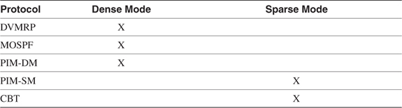
Sparse Versus Dense Topologies
A dense topology is one in which there are many multicast group members relative to the total number of hosts in an internetwork. Sparse topologies have few group members relative to the total number of hosts. Sparse does not mean that there are few hosts. A sparse topology might mean there are 2,000 members of a group, for example, spread among 100,000 total hosts.
No specific numeric ratios delineate sparse and dense topologies. It is safe to say, however, that dense topologies are usually found in switched LAN and campus environments, and sparse topologies usually involve WANs. What is important is that multicast routing protocols are designed to work best in one or the other topology and are designated as either dense mode protocols or sparse mode protocols. Table 5-3 shows the class to which each of the five multicast routing protocols belongs.
Table 5-3 Dense Mode and Sparse Mode Multicast Routing Protocols
Implicit Joins Versus Explicit Joins
As was previously observed, members may join or leave a group at any time during the lifetime of a multicast session, and as a result, the multicast tree can change dynamically. It is the job of the multicast routing protocol to manage this changing tree, adding branches as members join and pruning branches as members leave.
The multicast routing protocol may accomplish this task by using either an implicit or explicit join strategy. Implicit joins are sender-initiated, whereas explicit joins are receiver-initiated.
Multicast routing protocols that maintain their trees by implicit joins are commonly called broadcast-and-prune or flood-and-prune protocols. When a sender first initiates a session, each router in the internetwork uses reverse path broadcasting to forward the packets out every interface except the upstream interface. As a result, the multicast session initially reaches every router in the internetwork. When a router receives the multicast traffic, it uses IGMP to determine whether there are any group members on its directly connected subnets. If there are not, and there are no downstream routers to which the traffic must be forwarded, the router sends a poison-reverse message called a prune message to its upstream neighbor. That upstream neighbor then stops forwarding the session traffic to the pruned router. If the neighbor also has no group members on its subnets, and all downstream routers have pruned themselves from the tree, that router also sends a prune message upstream. The result is that the multicast tree is eventually pruned of all branches that do not lead to routers with attached group members. Figure 5-20 illustrates the broadcast-and-prune technique.

Figure 5-20 Broadcast-and-Prune Protocols First Use RPB to Forward a Multicast Session to All Parts of the Internetwork (a). Routers with No Connection to Group Members Then Prune Themselves from the Tree (b) so That the Resulting Tree Only Reaches Routers with Group Members (c)
For every (S, G) pair in its forwarding table, every router in the internetwork maintains state for each of its downstream interfaces. The state is either forward or prune. The prune state has a timer associated with it, and when the timer expires, the session traffic is again forwarded to neighbors on that interface. Each neighbor once again checks for group members and floods the traffic to its own downstream neighbors. If new group members are discovered, the traffic continues to be accepted. Otherwise, a new prune message is sent upstream.
The broadcast-and-prune technique is better suited to dense topologies than to sparse ones. The initial flooding to all routers, the periodic reflooding as prune states expire, and the maintenance of prune states all contribute to a waste of network resources when many or most branches are pruned. There is also a strong element of illogic in the maintenance of prune state, requiring routers that are not participating in the multicast tree to remember that they are not a part of the tree.
A better technique for sparse topologies is the explicit join, in which the routers with directly attached group members initiate the join. When a group member signals its router, via IGMP, that it wants to join a group, the router sends a message upstream toward the source, indicating the join. In contrast to a prune message, this message can be thought of as a graft message; the router sending the message is grafting itself onto the tree. If all of a router’s group members leave, and the router has no downstream neighbors active on the group, the router prunes itself from the tree.
Because traffic is never forwarded to any router that does not explicitly request the traffic, network resources are conserved. And because prune state is not kept by nonparticipating routers, overall memory is conserved. As a result, explicit joins scale better in sparse topologies. The argument can be made, of course, that explicit joins always scale better, regardless of whether the topology is sparse or dense. Table 5-4 shows which of the five multicast routing protocols use implicit joins and which use explicit joins.
Table 5-4 Implicit Join and Explicit Join Protocols

Source-Based Trees Versus Shared Trees
Some multicast routing protocols construct separate multicast trees for every multicast source. These trees are source-based trees, because they are rooted at the source. The multicast trees that have been presented in previous sections have been source-based trees.
You have learned that multicast trees can change during the lifetime of a multicast session as members join and leave the group, and that it is the responsibility of the multicast routing protocol to dynamically adapt the tree to these changes. However, some parts of the tree might not change. Figure 5-21 shows two multicast trees superimposed onto the same internetwork. Notice that although the trees have different sources and different members, their paths pass through at least one common router.

Figure 5-21 These Two Multicast Trees Have Different Shapes, but They Both Pass Through the Single Router RP
Shared trees take advantage of the fact that many multicast trees can share a single router within the network. Rather than root each tree at its source, the tree is rooted at a shared router called (depending on the protocol) the rendezvous point (RP) or core. The RP is predetermined and strategically located in the internetwork. When a source begins a multicast session, it registers with the RP. It may be up to the source’s directly connected router to determine the shortest path to the RP, or it may be up to the RP to find the shortest path to each source. Explicit joins are used to build trees from routers with attached group members to the RP. Rather than the (S, G) pair recorded for source-based trees, the shared trees use a (*, G) state. This state reflects that fact that the RP is the root of the tree to the group and that there may be many sources upstream of the RP. More importantly, a separate (S, G) pair must be recorded for each distinct source on a source-based tree. Shared trees, on the other hand, record only a single (*, G) for each group.
The impact of the (S, G) entries can be demonstrated with a few simple calculations. Suppose in some source-tree, flood-and-prune multicast domain, there are 200 multicast groups and an average of 30 sources per group. Each router must record 30 (S, G) entries for each group, or 30 * 200 = 6000 entries. If there are 150 sources in each of the 200 groups, the entries increase to 150 * 200 = 30,000.
Note
Keep in mind that with interactive multicast applications, many group members (receivers) are also sources (senders).
In contrast, shared tree routers record a single (*, G) entry for each group. So if there are 200 groups in a shared-tree multicast domain, the RP records 200 (*, G) entries. Most significantly, this number does not vary with the number of sources. Another way of stating these facts is that source-based trees scale on an order of (SG * GN), and shared trees scale on an order of (GN), where GN is the number of groups in the multicast domain and SG is the number of sources per group. Impact is greatly reduced on non-RP routers also, because they do not keep state for groups for which they do not forward packets. These routers record a single (*, G) entry for each active downstream group.
This scalability means that shared trees are generally preferable in sparse topologies. As usual, however, there are trade-offs. First, the path from the source through the RP may not be the optimum path to every group member for every group. Reexamining Figure 5-21, notice that a member of group 2 is attached to router R5. The optimal path from the source S2 to this group member is R2-R1-R5. But the source traffic must reach the RP first, so the path taken is R2-R3-RP-R4-R5. RPs must be chosen carefully to minimize suboptimal paths. Another drawback is that the RP can become a bottleneck when there are multiple high-bandwidth multicast sessions. Because of both suboptimal paths and RP congestion, latency can become a problem in poorly designed shared tree internetworks. The RP also represents a single point of failure. Finally, shared trees can be difficult to debug.
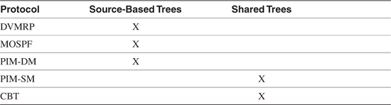
Table 5-5 shows which multicast routing protocols use source-based trees and which use shared trees. Comparing this table with Table 5-4, you can see that although MOSPF uses explicit joins, it also uses source-based trees. The converse situation is never true—a protocol using shared trees must always use explicit joins, because it has no other way to maintain loop-free trees.
Table 5-5 Source-Based Tree and Shared Tree Protocols
Multicast Scoping
You have seen in the preceding discussions of multicast routing issues that although multicast routing certainly uses fewer network resources than other strategies, such as replicated unicast or simple flooding, it can still be wasteful in some circumstances. This is particularly true of broadcast-and-prune protocols when used in sparse topologies. In some instances, a multicast source and all group members can be found close together in relation to the size of the entire internetwork. In such a case, a mechanism that limits the multicast traffic to the general area on the internetwork in which the members are located would help conserve resources. There also may be cases in which, for security or other policy reasons, the extent of the multicast traffic must be limited.
When multicast traffic is confined to "islands," the traffic is scoped. Put another way, multicast scoping is the practice of putting boundaries on the reach of multicast traffic.
TTL Scoping
One method for establishing boundaries to limit the scope of multicast traffic is to set a special filter on outgoing interfaces that checks the TTL value of all multicast packets. Only packets whose TTL value, after the normal decrement performed by the router, exceeds a configured threshold are forwarded. All other multicast packets are dropped.
Figure 5-22 shows an example. On this router, a multicast packet arrives on interface E2 with a TTL of 13. The router decrements the packet’s TTL to 12. Interface E0 has a multicast TTL threshold of 0, which is the default; no multicast packets are blocked based on their TTL. Therefore, a copy of the packet is forwarded out E0. Likewise, a copy of the packet is forwarded out interface E1, because its TTL threshold is set to 5, which is less than the packet’s TTL. However, the packet is not forwarded out E3. That interface’s TTL threshold is 30, meaning that only packets whose TTL value is greater than 30 can be forwarded.

Figure 5-22 Multicast Packets Are Forwarded Only Out Downstream Interfaces Whose TTL Threshold Is Less Than the Outgoing Packet’s TTL
TTL scoping has been used on the MBone for some time. The MBone is constructed of regional multicast networks connected through the Internet by IP-over-IP tunnels. Table 5-6 shows typical TTL thresholds used to restrict multicast traffic in the MBone. If you want some traffic to stay within a single site—high-bandwidth real-time video, for example—you configure the source application to send packets with a TTL no higher than 15.
Table 5-6 MBone TTL Thresholds

TTL scoping has several shortcomings. First, it is inflexible. An interface’s TTL threshold applies to all multicast packets. If you want some multicast sessions to pass the threshold and others to be restricted by it, the separate applications sourcing the sessions must be manipulated. This leads to the second problem: Users must be trusted to set the TTLs in their multicast applications correctly. If a session is sourced with a too-high TTL, it will pass outside the boundary you have set.
Another problem with TTL scoping is that it is difficult to implement in all but the simplest topologies. As your multicast internetwork grows in both scale and complexity, predicting the correct thresholds to contain and pass the correct sessions becomes a challenge.
Finally, TTL scoping can cause inefficiencies with broadcast-and-prune protocols. Figure 5-23 demonstrates the problem. The internetwork is a multicast site, and the boundary router has a TTL threshold of 8 configured on the interfaces leading to other parts of the internetwork. The multicast source is generating a session in which the TTL of all packets is set to 8, in keeping with local policy, to limit its traffic to the multicast site. There are no group members anywhere along the left branch of the tree, so those routers should prune themselves all the way back to the source’s directly connected router. In fact, you can see that one router has sent a prune message upstream to its neighbor.

Figure 5-23 The TTL Multicast Filter at the Boundary Router Is Preventing It from Sending a Prune Message Upstream
The problem is with the boundary router and its configured TTL filter. When the multicast packets reach this router, the packets are discarded at both downstream interfaces, because the packets’ TTL values are less than the TTL threshold. This is expected behavior. However, the packet discards also mean that no IGMP queries for group members take place. Without the queries, the router does not send a prune message back upstream. As a result, multicast traffic continues to be forwarded unnecessarily through all the routers leading to the boundary router.
Administrative Scoping
Administrative scoping, described in RFC 2365,7 takes a different approach to bounding multicast traffic. Rather than filter on TTL values, a range of Class D addresses is reserved for scoping. Filtering on these group addresses can then set boundaries. The reserved range of multicast addresses is 239.0.0.0–239.255.255.255.
The administratively scoped address space can be further subdivided in a hierarchical manner. For example, RFC 2365 suggests using the range 239.255.0.0/16 for local or site scope and the range 239.192.0.0/14 for organizationwide scope. An enterprise is, however, free to utilize the address space in any way it sees fit. In this regard, the reserved Class D range is similar to the RFC 1918 addresses reserved for private use. And like those addresses, the administratively scoped multicast address space is nonunique. Therefore, it is important to set filters for 239.0.0.0–239.255.255.255 so that none of the addresses in that range leak into the public Internet.
You have encountered both TTL scoping and address-based scoping already in this chapter and elsewhere in this book. Recall that the TTL for IGMP and OSPF packets is always set to 1 to prevent the packets from being forwarded by any receiving router. In this way, the scope is set to the local subnet. Similarly, routers do not to forward packets whose addresses are in the range 224.0.0.0–224.0.0.255. This range, which includes all the addresses shown in Table 5-1, is also scoped to the local subnet.
Operation of the Distance Vector Multicast Routing Protocol (DVMRP)
DVMRP uses the broadcast-and-prune method to build a separate source-based tree for every multicast source. It uses a variant of RIP to discover the shortest path to the source—hence the name Distance Vector Multicast Routing Protocol. Each multicast tree is maintained dynamically by pruning and grafting branches as group members leave and join the group.
DVMRP uses seven packet types:
• DVMRP Probe
• DVMRP Report
• DVMRP Prune
• DVMRP Graft
• DVMRP Graft Acknowledgement
• DVMRP Ask Neighbors2
• DVMRP Neighbors2
All the packets have a destination address of 224.0.0.4, the reserved All DVMRP Routers address (see Table 5-1). The uses of the various packet types are described in the following sections, and the section "DVMRP Packet Formats" gives a detailed description of the packet formats.
There are several versions of DVMRP. Version 1 is described in RFC 1075,8 and version 3, the most recent version, is described in an Internet draft.9 This chapter describes version 3 of the protocol. You should be aware that earlier versions of DVMRP vary significantly both in functionality and in packet formats. While an effort is made in this section to note differences between DVMRPv3 and some earlier versions, coverage of all the differences would make the section unacceptably long and complex. In this section, "DVMRP" is understood to mean DVMRPv3 unless otherwise noted. If you are working with an earlier version or have an interest in the differences, you should read RFC 1075, the relevant mgated documentation, or the software documentation of the router supporting the earlier version.
Note
Most routers running DVMRP are found on the MBone, and most of those run a version of mrouted or mgated.
Cisco IOS Software does not support a full implementation of DVMRP; however, it does support connectivity to a DVMRP network such as the MBone.
Neighbor Discovery and Maintenance
The first task when a DVMRP router comes online is to discover its neighbors using Probe packets. Each Probe packet contains the following information:
• A set of flags describing the originating router’s DVMRP capabilities. These flags are used to determine backward compatibility with earlier versions of the protocol.
• A generation ID, which is used to detect a change in a neighbor state.
• A list the addresses of neighbors from which the originating router has received probes.
Out of all this information, the most fundamental is the list of neighbor addresses. When a DVMRP router receives a Probe packet, it records the address of the originating router and the interface on which the probe was received. Recall that the receiving router never forwards any packet with a destination address from the 224.0.0.0/24 range. Both because the Probe packet has a destination address of 224.0.0.4, and because it is originated with a TTL of 1, the receiving DVMRP router knows that the originator is a directly connected neighbor. When the router sends its own probes, it lists all the neighbor addresses it has learned on the subnet on which the probe is sent. When a router sees its own IP interface address in a neighbor’s probe, it knows that two-way communication is established with the neighbor.
After a neighbor has been discovered, probes also are used as keepalives. Probes are sent at 10-second intervals, and a neighbor is declared dead if a probe is not received from it within 35 seconds.
Earlier versions of DVMRP do not use Probe packets. Instead, they discover neighbors upon reception of route advertisement messages from their neighbors.
During the neighbor discovery process, earlier versions of DVMRP would, when discovering more than one router on a subnet with group members, select a designated router. The designated router, which is the only router that sends multicast session packets and IGMP queries onto the subnet, is the router with the lowest IP address on that subnet. DVMRPv3 determines a designated router through the IGMPv2 querier election process rather than by reading the source IP addresses of received route advertisement messages.
As you learned previously, a broadcast-and-prune multicast routing protocol must store prune states. If the router is restarted, however, it cannot know what prunes have been sent or received. It may also be slow to reestablish multicast forwarding if it has to wait for the next regularly scheduled route update. The generation ID, a nondecreasing 32-bit number derived from some changing reference such as a time-of-day clock, is designed to alleviate these problems. When a DVMRP router restarts, its generation ID changes. When neighbors detect this changed number in the router’s Probe messages, they flush all prune information previously received from the router. They also immediately send a copy of their routing table to the neighbor. Multicast data will again flow to the restarted router due to the cleared prune information, and the router must again prune itself or remain a part of the tree.
The DVMRP Routing Table
The primary purpose of the DVMRP routing table is to determine, for each multicast source, the upstream interface for that source. As explained earlier in the chapter, this process is important for loop avoidance; if a packet is received from a source on any interface other than the upstream interface—the interface closest to the source—the packet must be discarded.
DVMRP uses a variant of RIP to advertise the complete routing table plus all directly connected multicast-enabled subnets. The routes are advertised in DVMRP Report messages, sent to every neighbor using the All DVMRP Routers address 224.0.0.4. Route updates are sent every 60 seconds, known as the Route Report Interval. The exception to this rule occurs when a new neighbor is discovered by the probe process. In this case, the routing table is immediately unicast to the new neighbor. Flash updates also can be used to shorten reconvergence times.
If a route is not updated within 140 seconds, the route expiration time, the route is put into holddown for two report intervals (120 seconds). During this time, the route is advertised with a metric of infinity; when the holddown time expires, the route is removed from the routing table.
The metric associated with each route is hop count, with infinity defined as 32 hops. However, a route may have a metric in the range of 1 through 63. The metric values 1 through 31 indicate reachable sources; the values 33 through 63 are used to indicate route dependencies.
For pruning to work correctly, a DVMRP router must be aware of the downstream neighbors that depend on it to forward packets from particular multicast sources. For each source network, a downstream router signals a route dependency to an upstream router by sending a poison reverse route to the upstream router. The poison reverse route contains a metric that is the advertised metric plus infinity. Suppose, for example, that router A advertises network 172.16.1.0/24 to router B, with a hop count of 3. Router B determines that router A is the upstream router toward this subnet. Router B must signal to router A that it is dependent on router A for multicast traffic from sources on this subnet. Therefore, router B advertises 172.16.1.0/24 to router A with a metric of 35 (3 + 32). Router A recognizes this advertisement as a route dependency.
Yet another function of the DVMRP routing table is the selection of a designated forwarder. When multiple upstream routers are connected to a multiaccess network, as in Figure 5-24, only the designated forwarder forwards multicast packets downstream. This prevents multiple copies of the same packets from being forwarded onto the multiaccess network. When two or more routers on a multiaccess network exchange routes, they can tell which of the routers is closest to the source. That router is the designated forwarder for that source network. In Figure 5-24, upstream router B would be the designated forwarder for the source shown, because it is only one router hop from the source; upstream router A is two hops away. If the routers are an equal distance from the source, the router with the numerically lower IP address on the shared network becomes the designated forwarder.
Figure 5-24 When Multiple Upstream Routers to a Source Are Connected to the Same Data Link, a Designated Forwarder Is Elected
DVMRP Packet Forwarding
When a router first receives a multicast packet from a particular source, an RPF check is performed, using the routing table, to verify that the packet arrived on the upstream interface for the packet’s source. If the packet arrived on any other interface, it is dropped. If the packet did arrive on the upstream interface, the (S, G) pair is recorded in a forwarding table, and a copy of the packet is forwarded to all downstream dependent neighbors. The router also uses IGMP to query for group members on each of its leaf networks—that is, networks with no neighbors. A copy is forwarded to any leaf networks that contain group members.
If there are no downstream dependent neighbors, and no leaf networks with group members, the router sends a prune message to the upstream router. If the upstream router also has no local group members, and if it has received a prune message from all of its downstream dependent neighbors, it sends a prune message of its own to its upstream neighbor. In this way, the multicast tree is dynamically pruned until only branches leading to active group members remain.
A prune message contains a prune lifetime, which indicates how long an upstream router should hold a prune state before resuming the forwarding of packets from the source in question to the pruned router. The default prune lifetime is 2 hours. If the router receiving a prune is itself sending a prune upstream, the prune lifetime is set to the minimum of either 2 hours or the remaining lifetimes of any downstream prunes received for the same (S, G) pair.
As discussed previously, a host can signal its desire to join a multicast group at any time by sending an IGMP membership report message to its local router. If that router has previously pruned itself from the tree delivering packets from that group, it must now graft itself back onto the tree. The router does this by sending a DVMRP Graft message upstream. Grafts are sent hop by hop upstream until an active branch of the multicast tree is found.
If a router sends a graft message and does not begin receiving traffic for the requested group, it must have a mechanism by which it knows whether the source has stopped transmitting, or the graft has been lost. Therefore, at each hop, an upstream router acknowledges the receipt of a Graft message by sending a Graft Ack message to its downstream neighbor. The originator of the graft also sets a Graft Retransmission timer; if a Graft Ack is not received before the timer expires, another Graft message is sent, and the timer is reset. The initial period of the Graft Retransmission timer is 5 seconds, and subsequent periods are calculated using a binary exponential backoff algorithm.
DVMRP Message Formats
The IP header of a DVMRP packet specifies protocol number 2. Note that this is the same protocol number used by IGMP, a legacy of DVMRP’s beginnings as a subset of that protocol. This section describes DVMRPv3 formats; for a description of earlier formats, see RFC 1075 or other appropriate documentation.
DVMRP Message Header
Figure 5-25 shows the format of the DVMRP header, which begins every DVMRP message.
Figure 5-25 The DVMRP Message Header
The fields for the DVMRP message are described as follows:
• Type is the IGMP type number, which is set to 0x13 for all DVMRP messages. RFC 1075 specifies a separate 4-bit Version field and 4-bit Type field in this position, in which the version is 0x1 and the type is 0x3. Note that the resulting 8 bits of the version 1 header is 0x13, the same as version 3, making version 3 backward-compatible. The actual DVMRPv3 version is specified in the Major Version field.
• Checksum is a standard IP-style checksum, using a 16-bit one’s complement of the one’s complement of the DVMRP message.
• Minor Version and Major Version are set to 0xFF and 0x03, respectively, for all DVMRPv3 messages.
• Code specifies the DVMRPv3 message type. Table 5-7 shows the possible values of the code field and the corresponding message types.
Table 5-7 DVMRP Message Types by Code Value

The Ask Neighbors (code 3) and Neighbors (code 4) messages are obsoleted by the Ask Neighbors 2 (code 5) and Neighbors 2 (code 6) messages. None of these messages have yet been discussed; they are used by such diagnostic commands as mrinfo and mstat. They are discussed in this context in the troubleshooting section of Chapter 6, "Configuring and Troubleshooting IP Multicast Routing."
DVMRP Probe Message Format
DVMRP Probe messages serve four functions:
• They allow routers to locate each other by listing all DVMRP-speaking routers detected by the originating router on the originating interface.
• They provide a means for DVMRP routers to communicate their capabilities to each other.
• They enable the selection of a designated forwarder when there are multiple paths to a downstream group member.
• They provide a keepalive function by being transmitted every 10 seconds. If a probe is not heard from a neighbor within 35 seconds, the neighbor is declared dead.
Figure 5-26 shows the format of the probe message.

Figure 5-26 The DVMRP Probe Message
The fields for the DVMRP Probe message are described as follows:
• Capabilities uses eight of the reserved bits in the header for capability flags. The Probe message is the only DVMRP message to modify the header fields. Table 5-8 lists the capabilities flags and their meanings. If the flag is set to 1, the corresponding capability is supported by the originating router.
Table 5-8 DVMRP Capabilities Flags

• Generation ID is a nondecreasing 32-bit number used for detecting when a router has restarted, without having to wait for an entire report interval to pass. When a change in the generation ID is detected, any prune information from the originating router is declared invalid and is flushed. If the prune information has been sent upstream, a Graft message is sent. The result of this process is that the restarted router is treated as a new router on multicast trees, and the broadcast-and-prune process is begun anew.
• Neighbor Address lists the neighbors from whom the originating router has received Probe messages on the originating interface.
DVMRP Route Report Message Format
Route Report messages, depicted in Figure 5-27, are sent every 60 seconds. The Route Report consists of a list of one or more netmasks, and for each netmask, a list of one or more source network addresses and associated metrics corresponding to the netmask. Although the lengths of the source networks in Figure 5-27 are all 3 octets, in reality the lengths may vary, as described in this section.

Figure 5-27 DVMRP Route Report Message Format
The fields for the DVMRP Route Report Message are defined as follows:
• Mask is a netmask. The first octet of the netmask is always assumed to be 255, so only the last 3 octets are included in the Mask field. Note that this assumption means that DVMRP routes can never be aggregated into addresses with a prefix length less than 8.
• Source Net is a source network address whose prefix length corresponds to the netmask preceding it. The length of the Source Net field varies according to the netmask. For example, if the netmask field is 255.0.0, the field is describing a mask of 255.255.0.0 (remembering that the first octet is assumed to be 255). The Source Net fields following such a netmask are all 2 octets, corresponding to the prefix length specified.
A default route is specified with a netmask of 0.0.0 and a 1-octet source net of 0. DVMRP routers always interpret this as 0.0.0.0/0, not 0.0.0.0/8.
• Metric is the sum of the interface metrics between the router originating the report and the source network. The metric is a hop count, with 32 signifying infinity. However, the full range of the metric value is 1–63. As described in the section "The DVMRP Routing Table," a router signals a dependency to an upstream router by advertising a poison reverse route in which the metric is the received metric plus infinity (32). Therefore, metric values between 33 and 63 indicate a downstream dependency.
DVMRP Prune Message Format
Figure 5-28 shows the format of the Prune message.

Figure 5-28 The DVMRP Prune Message Format
The fields for the DVMRP Prune message are defined as follows:
• Source Host Address is the IP address of the originating host.
• Group Address is the IP address of the group to be pruned.
• Prune Lifetime is the time, in seconds, that the upstream neighbor is to keep the prune. This value is either the minimum remaining lifetime of all downstream prunes received for the group address or, if there are no downstream prunes, the default prune lifetime of 2 hours.
• Source Network Mask is the netmask of the source network of the group to be pruned. This field is optional, and it is included only if the upstream neighbor has indicated in its Probe messages that it understands netmasks.
DVMRP Graft Message Format
Figure 5-29 shows the format of the Graft message.
Figure 5-29 The DVMRP Graft Message Format
The fields for the DVMRP Graft message are defined as follows:
• Source Host Address is the IP address of the originating host.
• Group Address is the IP address of the group to be grafted.
• Source Network Mask is the netmask of the source network of the group to be grafted. This field is optional, and it is included only if the upstream neighbor has indicated in its Probe messages that it understands netmasks.
DVMRP Graft Acknowledgement Message Format
Figure 5-30 shows the format of the Graft Acknowledgement message. With the exception of the Code field in the header, the format is identical to that of the Graft message that it is acknowledging.
Figure 5-30 The DVMRP Graft Acknowledgement Message Format
DVMRP Ask Neighbors 2 Message Format
The DVMRP Ask Neighbors 2 message is one of two messages (along with the Neighbors 2 message, discussed in the following section) that are used for troubleshooting. The "2" distinguishes the message from the obsolete Ask Neighbors message. The Ask Neighbors 2 message, shown in Figure 5-31, is unicast to a specified destination. When a router receives an Ask Neighbors 2 message, it should respond by unicasting a Neighbors 2 message to the originator. As the figure shows, the message is merely the DVMRP header with the code set to 0x5.

Figure 5-31 The DVMRP Ask Neighbors 2 Message Format
DVMRP Neighbors 2 Message Format
A DVMRP router in response to an Ask Neighbors 2 message sends the Neighbors 2 message, shown in Figure 5-32. The message is unicast to the originator of the Ask Neighbors 2 message. The message indicates the sender’s DVMRP capabilities and lists the addresses of the sender’s logical interfaces. For each interface listed, the DVMRP parameters for the interface are specified, and the DVMRP neighbors known on that interface are listed.

Figure 5-32 The DVMRP Neighbors 2 Message Format
The fields for the DVMRP Neighbors 2 message are defined as follows:
• Capabilities specifies the DVMRP capabilities of the originating router. The field is the same as the Capabilities field of the Prune message, and its values are shown in Table 5-8.
• Local Address is the address of an interface on the router. If the interface is down or disabled, a single neighbor entry is associated with the interface, and the neighbor entry has an address of 0.0.0.0.
• Metric specifies the DVMRP metric of the interface.
• Threshold specifies the administrative scoping threshold of the interface.
• Neighbor Count specifies the number of neighbors listed for this interface.
• Neighbor is the IP address of a DVMRP neighbor known on this interface.
• Flags is a series of bits describing operational parameters of the interface. Table 5-9 lists the bits of this field and what flag each bit represents.
Table 5-9 Interface Flags in the Neighbor 2 Message
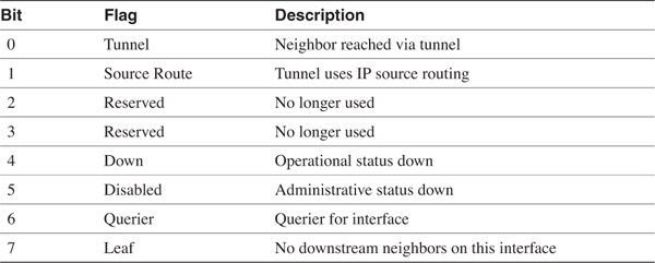
Operation of Multicast OSPF (MOSPF)
Multicast OSPF (MOSPF) offers an improvement over DVMRP in two aspects. First, it is a link-state protocol, whereas DVMRP is distance vector. That difference carries with it all the usual advantages of link state over distance vector: better convergence properties, better loop avoidance, and less periodic control traffic. The second improvement is that MOSPF is more scalable in a dense environment. This is partly due to its link-state algorithms, but also to the fact that MOSPF uses explicit joins rather than implicit joins via flood-and-prune.
Multicast OSPF is not a separate protocol from OSPF, but rather is an extension of that protocol, as indicated by the name of the RFC describing it.10 Three extensions to OSPF are defined to support multicast. First, a new LSA is defined, called the Group Membership LSA. Group Membership LSAs are LSA type 6.
The Options field is extended to include a flag, called the MC bit, which is used to indicate support for IP multicast. The Options field, described in Chapter 9 of Volume I, is carried in OSPF Hello and Database Description packets and in all LSAs. The implication of the MC bit is that OSPF and MOSPF routers can be intermixed in the same internetwork, with the MOSPF routers using the MC bit to indicate their multicast support. Routers with mismatched MC bits still become adjacent. However, only neighbors whose MC bits are set in their Database Description packets exchange Group Membership LSAs during their database synchronization process. And only LSAs with the MC bit set are used in the calculation of multicast shortest-path trees.
Finally, the rtype field of the Router LSA is extended to include a flag called the W bit. This flag indicates that the originating router is a wildcard multicast receiver. Wildcard multicast receivers are defined in the section "Inter-Area MOSPF."
Just as unicast OSPF uses a Dijkstra-based SPF algorithm to calculate shortest-path trees to unicast destinations, MOSPF calculates trees from multicast sources to multicast destinations. Both unicast trees and multicast trees are calculated from the same link-state database. A difference, however, is that whereas the unicast SPF trees are rooted at source routers, multicast SPF trees are rooted at source multicast subnets.
MOSPF Basics
The best place to begin describing MOSPF is at a local multiaccess medium to which a group member is attached. Like unicast OSPF, MOSPF elects a designated router and a backup designated router. All attached MOSPF routers should run IGMP on the local link to discover group members, but only the DR sends IGMP membership queries and listens for IGMP membership reports.
Recall from Table 5-4 that MOSPF uses explicit joins. When a group member sends an IGMP message indicating that it wants to join a group, the MOSPF DR creates an entry in its local group database. The local group database entry records the group and the attached network on which the group member resides. For example, the router in Figure 5-33 has three attached subnets, and there are three multicast group members on two of those subnets. Two of the group members, on separate subnets, belong to the same group. The router has to know only the groups and subnets on which the groups have members; it does not need to know each individual group member.

Figure 5-33 The Local Group Database Records Attached Groups and the Subnets on Which the Group Members Reside
The DR then originates a Group Membership LSA for each attached group. The LSA specifies the group address and the originating router ID and lists all the router’s attached networks on which members of the group reside. In some cases, the router itself may run multicast applications that make it a group member. The LSA includes a Type field in which the router can indicate that it is advertising itself as a group member.
The LSA is then flooded throughout the originating router’s area. The Group Membership (type 6) LSA is similar to a Network (type 2) LSA in two regards:
• Like a Network LSA, only a designated router originates a Group Membership LSA.
• Like a Network LSA, a Group Membership LSA only has area-wide scope. That is, the LSA is not flooded outside of the originating router’s area.
The objective of the LSA flooding is to ensure that all MOSPF routers in an area have a copy of all Group Membership LSAs originated in the area. As with unicast OSPF, all MOSPF routers in an area must have identical link-state databases. The only difference between an OSPF link-state database and an MOSPF database in a given area is the inclusion of the type 6 LSAs.
With synchronized databases, every MOSPF router in an area can calculate the same shortest path tree. The tree is rooted at the source network and has branches extending to every network containing a group member. However, the tree is not calculated immediately. Instead, it is calculated "on-demand," when the first multicast packet for the group arrives. This makes sense, because although the synchronized routers know where all destinations are, they may not yet know where the source is.
The SPF calculation knows where all routers with attached group members are based on the Group Membership LSAs. And it knows where the source is located based on the source and destination addresses of the first arriving packet for the group. The regular unicast Router and Network LSAs whose MC bits are set are then used to calculate the least-cost paths from the source to each destination.
The great advantage of the Group Membership LSA-based explicit joins, coupled with the on-demand SPF calculation, is that routers already know the location of the destination networks before the calculation is performed. So unlike flood-and-prune protocols such as DVMRP, packets are never forwarded to all parts of the routing domain. You might say that the MOSPF tree comes "prepruned."
Based on the results of the SPF calculation, entries are made into each router’s multicast forwarding table. The shortest-path tree is loop-free, and every router knows which interface is the upstream interface and which interfaces are downstream interfaces. Therefore, no RPF check is required, as it is with DVMRP. The forwarding table entry for a particular (S, G) pair indicates what upstream neighbor a matching packet should be received from and what downstream neighbors the packet must be forwarded to. The local group database also is used to make entries into the forwarding table for locally attached networks containing group members.
Keep in mind a few caveats about MOSPF. First, although unicast OSPF supports equal-cost multipath, MOSPF does not. The MOSPF shortest-path tree describes a single path between the source and all networks containing group members.
Second, if OSPF and MOSPF routers coexist on the same multiaccess network, care must be taken to ensure that the MOSPF router is elected the DR. If an OSPF router becomes the DR, no Group Membership LSAs are originated for any group members on the network, and consequently no multicast packets for the group are forwarded to the network.
Finally, an MOSPF router must clear its entire forwarding table and recalculate its shortest-path trees if the topology within the MOSPF domain changes. Therefore, it is important that the domain be as stable as possible.
Inter-Area MOSPF
The preceding section described how MOSPF behaves when the source and all group members are within the same area. Emphasis was placed on the fact that a Group Membership LSA is not flooded outside of its originating area. So what happens when group members are in one or more areas different from the source?
You know from Chapter 9 of Volume I that inter-area OSPF communications is managed by Area Border Routers (ABRs). ABRs are members of the backbone area and one or more nonbackbone areas. They learn all the destinations within each attached area via Router and Network LSAs, just as any other router in the area does. ABRs then create Network Summary (type 3) LSAs, which advertise the destinations in one attached area into the ABR’s other attached areas. Like type 1 and type 2 LSAs, type 3 LSAs are never flooded outside of the area in which they are originated. When an ABR receives a Network Summary LSA across the backbone area from another ABR, it creates its own Network Summary LSA to advertise that information into its attached nonbackbone areas. Figure 5-34 illustrates conceptually how ABRs use types 1, 2, and 3 LSAs.

Figure 5-34 Unicast OSPF ABRs Use Network Summary LSAs to Advertise Destinations Learned from One Attached Area into Other Attached Areas
MOSPF ABRs are perversely called inter-area multicast forwarders. There are both similarities and differences with the way unicast ABRs operate. An inter-area multicast forwarder knows what groups have members in each of its attached nonbackbone areas based on the Group Membership LSAs it has received in those areas. For each known group, the forwarder creates a new Group Membership LSA and floods the LSA into the backbone, as illustrated in Figure 5-35. So far, this behavior is very similar to the way an ABR uses type 3 LSAs to summarize information learned from type 1 and type 2 LSAs into the backbone.

Figure 5-35 Inter-Area Multicast Forwarders Use Group Membership LSAs to Advertise the Presence of Group Members in Their Nonbackbone Areas to the Backbone Area
Here the similarity to unicast ABRs ends. Unlike the way in which type 3 LSAs are used, an inter-area multicast forwarder does not send type 6 LSAs into a nonbackbone area to advertise the presence of groups outside the area. In Figure 5-35, for example, RT1 receives the type 6 LSA originated by RT2, advertising group C, but it does not create a type 6 LSA to advertise group C into area 1.
The result is that an SPF tree is calculated in the backbone for each group, and the tree’s branches extend to the inter-area multicast forwarder of each area containing group members. The nonbackbone areas have no knowledge of group members outside of their own area.
If the source for group C in Figure 5-35 is located in area 1, however, how do its packets reach members in areas 2 and 3? The answer is a wildcard multicast receiver. These devices advertise themselves by setting the W bit in the rtype field of their Router LSAs. Within an area, multicast traffic is always forwarded to all wildcard multicast receivers. In nonbackbone areas, an inter-area multicast forwarder (a multicast ABR) is always a wildcard multicast receiver.
When the source for group C in Figure 5-35 originates a group C packet, the packet is forwarded to RT1, the wildcard multicast receiver for area 1. RT1 also is a member of the backbone area, and so has calculated a shortest-path tree to all inter-area multicast forwarders whose attached areas contain members of group C. Seeing that RT2 is advertising group C members, the packet is forwarded to that router across the backbone. RT2, as a member of areas 2 and 3, has calculated separate SPF trees for group C in each area and forwards copies of the packet to the group C destinations.
Note
If there were any group C members in area 1, a copy of the packet would, of course, be forwarded over the local SPF tree to those members in addition to being forwarded to RT1.
Note that wildcard multicast receivers are unnecessary in the backbone area for intradomain traffic. For every group in the MOSPF domain, an SPF tree is calculated in area 0. The branches of the tree lead either to group members located in that area or to inter-area multicast forwarders attached to other areas. So if a source is located in the backbone area, its packets can be forwarded along the correct tree.
Inter-AS MOSPF
RFC 1584 provides for the routing of multicast packets into and out of an MOSPF domain. You know from Chapter 9 of Volume I that a router redistributing routes into an OSPF domain from some other routing protocol is called an Autonomous System Boundary Router (ASBR). An ASBR uses AS-External (type 5) LSAs to advertise destinations outside of the OSPF domain and ASBR Summary (type 4) LSAs to advertise their own location. These LSAs are flooded into all areas of the OSPF domain, with the exception of stub areas.
A router that connects an MOSPF domain to some other multicast routing domain (most likely DVMRP presently, and possibly some multicast EGP in the future) is called an inter-AS multicast forwarder. These routers behave very similarly to inter-area multicast forwarders. To forward multicast packets to destinations outside of the MOSPF domain, inter-AS multicast forwarders set the W bit in their Router LSAs and become wildcard multicast forwarders. When the routers are forwarding packets into the MOSPF domain from external sources, they become "proxy sources," with their external link serving as the root for the group’s SPF tree.
Like ASBRs, inter-AS multicast forwarders can be located in any area. Notice, however, that wildcard multicast forwarding capability is signaled by the W bit of type 1 LSAs, and type 1 LSAs are not flooded outside of an area. If the inter-AS forwarder is located in area 0, this is not a problem; the inter-area multicast forwarders already pull all multicast traffic to the backbone. If the inter-AS forwarder is located in a nonbackbone area, however, that area’s inter-area forwarder also must become a wildcard forwarder for the backbone area. Therefore, it is recommended that inter-AS multicast forwarders be located only in area 0.
It is also recommended that inter-AS forwarders be placed carefully within the MOSPF domain. Because all multicast traffic within the domain is forwarded to these routers, links leading to the routers can easily become congested.
MOSPF Extension Formats
This section describes only the formats of the multicast extensions to OSPF. For a complete description of all OSPF packets and LSAs, see Chapter 9 of Volume I.
Group Membership LSA Format
The Group Membership LSA carries the standard LSA header and has a type number of 6. Figure 5-36 shows the format for the Group Membership LSA. Only MOSPF-designated routers originate Group Membership LSAs. Notice in the format that no metric is associated with this LSA.

Figure 5-36 The MOSPF Group Membership LSA Format
The fields for the Group Membership LSA are defined as follows:
• Link State ID carries the address of the multicast group being advertised.
• Advertising Router is always the router ID of the MOSPF designated router on the multiaccess network, because only the DR can originate type 6 LSAs.
• Vertex Type specifies whether the destination is a router (type = 1) or a transit network (type = 2). Type 1 is specified if the originating router is running some application that requires it to be a member of a multicast group. Transit network just refers to the originating router’s directly connected network over which packets must pass to reach the attached group members.
• Vertex ID is the originating router’s router ID.
Extended Router LSA Format
Figure 5-37 shows the format of a Router (type 1) LSA that has been extended to support MOSPF. The format is identical to the format shown in Figure 9.55 of Volume I, with the exception of the addition of the W bit in the rtype field. The W bit is set by inter-area and inter-AS multicast forwarders to indicate to other MOSPF routers in an area that they are wildcard multicast forwarders.

Figure 5-37 The Router LSA Format, with the W Bit Added to the rtype Field for MOSPF Support
Extended Options Field Format
The Options field, shown in Figure 5-38, is a part of all OSPF Hello and Database Description packets and a part of the header of all LSAs. The other flags of this field are described in Chapter 9 of Volume I, but the pertinent flag for this chapter is the MC bit. When set, this bit indicates that the originating router is multicast-capable.

Figure 5-38 The Options Field Format
The MC bit in Hello packets does little more than signal multicast capability. Two routers will still become adjacent, even if one sets the MC bit and the other does not. The real use of the MC bit comes into play with the Database Description packets and with LSAs.
During database synchronization, an MOSPF router will send the type 6 LSAs in its database to its neighbor only if the neighbor’s DD packets have the MC bit set. Likewise, only LSAs with the MC bit set are used in the MOSPF SPF calculation.
Operation of Core-Based Trees (CBT)
DVMRP and MOSPF have two limitations in common. First, they are both dense-mode protocols and do not scale well in sparse topologies. That is, when there are few group members relative to the total number of hosts in an internetwork, and the group members are widespread across the internetwork, both DVMRP and MOSPF consume an unacceptable amount of network resources to reach those group members. Much of that resource consumption is in the overhead necessary to calculate and hold state for individual trees rooted at each source. Second, both protocols are limited to a single unicast routing protocol for determining multicast trees—DVMRP to its own RIP-based protocol, and MOSPF to OSPF. Core-Based Trees (CBT), on the other hand, is a protocol-independent, sparse-mode, shared-tree protocol.
Protocol-independent means that CBT can use any underlying unicast routing protocol to find sources and other CBT routers and build its trees. Besides adding flexibility, overhead is reduced by using the existing routing protocols instead of adding another one just for multicast. And CBT trees are rooted at core CBT routers rather than at source networks. The cores can be located anywhere within an internetwork, and many group trees can be rooted at the one core, making the protocol more suitable for sparse multicast topologies.
There are currently three versions of CBT. CBTv2, described in RFC 2189,11 obsoletes CBTv1. There is also a proposed CBTv3. All three versions are experimental, and none have seen widespread deployment. Indicative of this experimental status, neither CBTv2 nor CBTv3 is backward-compatible with its preceding version. This chapter focuses exclusively on CBTv2; when the term "CBT" is used, it refers to that version of the protocol.
CBT Basics
CBT uses nine message types:
• JOIN_REQUEST
• JOIN_ACK
• ECHO_REQUEST
• ECHO_REPLY
• QUIT_NOTIFICATION
• FLUSH_TREE
• Candidate Core Advertisement
• Bootstrap message
• HELLO
With a single exception discussed in the section "CBT Designated Routers," all CBT messages are sent to the reserved multicast address 224.0.0.15 (see Table 5-1). The messages are transmitted with a TTL of 1, which means all CBT information is passed hop by hop through the multicast domain. The format of each message type is detailed in the section "CBT Message Formats."
Like the other IP multicast routing protocols, CBT is informed that an attached host wants to join a group via IGMP Membership Report messages. CBT uses explicit joins, so when a CBT router must forward packets for a particular group, it must first graft itself to that group’s multicast tree. The router first examines its unicast routing table for the location of the core for the particular group and then forwards a JOIN_REQUEST message upstream on the path toward the core. The message contains three important pieces of information:
• The multicast group address
• The address of the core
• The address of the originator
Note
How the router knows where to find the core is the topic of the following section, unsurprisingly titled "Finding the Core."
When the next-hop router receives the JOIN_REQUEST message, it examines the group address and the core address. Based on this information, the router establishes that it is one of the following:
• The core router
• Attached to the group’s multicast tree (an on-tree router)
• Neither the core nor an on-tree router
If the router is either the core or an on-tree router, it sends a JOIN_ACK message to the originator of the JOIN_REQUEST, indicating that the originator has successfully joined the tree. The router adds the interface on which the JOIN_REQUEST was received to its forwarding table entry for the group and begins forwarding packets on the interface.
If the router is neither the core nor on the group tree, it must also join the tree. The router consults its own unicast routing table for the location of the core and forwards a copy of the JOIN_REQUEST message upstream. It also begins a transient join state, in which the group, the interface on which the JOIN_REQUEST was received, and the interface on which the JOIN_REQUEST was transmitted is recorded. A timer is started, and if a JOIN_ACK is not received within 7.5 seconds (the transient timeout period), the transient join state is deleted, and the join is considered unsuccessful.
In CBT parlance, the upstream interface toward the core is the parent interface, and the downstream interface toward the group member is the child interface. Likewise, an upstream neighbor is a parent router, and a downstream neighbor is a child router. Once a tree is established by the reception of a JOIN_ACK, a child router sends an ECHO_REQUEST message to its parent router every 60 seconds. The ECHO_REQUEST message contains only the address of the originating child router. The parent router responds with an ECHO_REPLY message, which lists all groups for which the parent router forwards packets on that link.
If an ECHO_REPLY is not heard within 70 seconds, the parent router is declared unreachable. Likewise, a particular group is declared invalid if it has not been listed in an ECHO_REPLY in the past 90 seconds. The child router then sends a QUIT_NOTIFICATION upstream to the parent router and a FLUSH_TREE downstream to each of its own child routers. The FLUSH_TREE lists all group addresses that have become invalid, and the receiving child routers flush all information about the listed groups from the forwarding tables. The child routers then send the appropriate FLUSH_TREE messages to their own children. The process continues until all branches of the tree downstream of the failed router are deleted.
The QUIT_NOTIFICATION message also is used for pruning. If a router learns via IGMP Leave Group messages that it no longer has any attached members of a particular group, it sends a QUIT_NOTIFICATION message to its parent router, listing the group address to be pruned. If that parent, in turn, has no attached members of the group and no other child interfaces for the group, it too sends a QUIT_NOTIFICATION upstream. The branch continues to be pruned back to either an active on-tree router or to the core.
Finding the Core
The obvious prerequisite for CBT routers to build trees to the core is for the routers to know what router is the core. One way to meet this requirement is for all routers to be preconfigured with the address of the core router for each group. This approach may be fine for small multicast internetworks, and it offers good network control, but the administrative requirements certainly do not scale to larger internetworks.
Another way is to use the bootstrap mechanism. Using this method, a set of routers within the CBT domain are configured as candidate core routers. These routers exchange Candidate Core messages, and one of them is elected a bootstrap router (BST) based on a priority or, if all priorities are equal, the router with the highest IP address. The other candidate core routers then unicast Candidate Core messages to the BSR every 60 seconds as a keepalive. Based on these Candidate Core messages, the BSR assembles a candidate core set (CC-set) and advertises the set to all CBT routers in the domain via Bootstrap messages. When a router is asked to join a group via IGMP, it runs a hash algorithm against the CC-set and determines the correct core router for the group.
The same bootstrap protocol is used by both CBT and PIM-SM. Because this chapter places a closer focus on the latter protocol, the bootstrap mechanism is summarized here and is described in greater detail in the section "Protocol-Independent Multicast, Sparse Mode (PIM-SM)."
CBT Designated Routers
CBT uses HELLO messages to elect a designated router on multiaccess networks. The rationale for using a CBT DR is the same as that for DVMRP-designated forwarders and MOSPF DRs. Because CBT does not use an RPF check when forwarding packets, a DR is especially important for preventing loops when there are multiple upstream paths to the core, as in Figure 5-39.

Figure 5-39 CBT Elects a Designated Router on Multiaccess Networks to Manage Multiple Upstream Paths to the Core
Each CBT interface is configured with a preference value between 0 and 255, and this value is carried in the HELLO message. A value between 1 and 254 indicates that the router is eligible to become the DR, with the lower number indicating a higher preference—that is, a router with a preference of 10 is "more eligible" than a router with a preference of 20. A preference of 0 indicates that the router is the DR.
When a CBT router first becomes active on a multiaccess link, it sends two HELLO messages in succession to advertise its presence and its preference value. The router then listens for HELLOs, with one of the following three results:
• A HELLO with a lower preference value is heard from another router on the network.
• All HELLOs heard on the network have a higher preference value.
• No other HELLOs are heard on the network.
In the first case, the new router knows that the router with the lower preference value is elected as the DR. In the other two cases, the new router assumes the role of DR and advertises that fact by setting the preference to 0 in its HELLOs. If all HELLOs have equal preference values, the router with the lowest IP address is elected as the DR.
In steady state, the DR sends a HELLO every 60 seconds both as an advertisement of its status and as a keepalive. The DR also sends a HELLO in response to a HELLO from a new router. Other routers do not send HELLOs or respond to HELLOs from new routers.
In some cases, the elected DR may not be on the path to the core. Suppose that RTA in Figure 5-39 is elected as the DR, but RTB is the best next-hop router to the core. In this case, when RTC forwards a JOIN_REQUEST to RTA, RTA unicasts the JOIN_REQUEST back across the multiaccess link to RTB. This redirection occurs only with JOIN_REQUESTs; when RTB sends a JOIN_ACK, the message is sent directly to RTC.
Member and Nonmember Sources
You might have noticed that so far nothing has been said about how sources deliver their traffic to the core. In many multicast applications, a sender also is a group member. CBT takes advantage of this fact, so a sender that is also a group member—a member source—can reach the core by virtue of the fact that its directly connected router is on-tree. Figure 5-40 illustrates this concept. Here, the host labeled SG1 is a member source of group 1. Because the host is a group member, its local router has already joined the CBT tree for group 1. Therefore, when SG1 sources packets for group 1, the local router can forward the packets up the tree.

Figure 5-40 SG1 Is a Member Source for Group 1. Its Local Router Has Joined the Group 1 Tree and Forwards Packets up the Tree Toward the Source
A fundamental characteristic of CBT is described in this behavior. Namely, CBT uses bidirectional trees. In other words, multicast traffic can not only travel downstream on the tree from the core to group members, but it also can travel upstream on the tree from a member source to the core. This is in contrast to the other shared-tree protocol, PIM-SM, which uses unidirectional trees.
Of course, not all sources are group members. Therefore, CBT also must have a mechanism for accommodating these nonmember sources. The mechanism is a simple IP-in-IP tunnel, as shown in Figure 5-41. Here, the same host is originating multicast traffic for group 1, but the host itself is not a member of the group. When its local router receives the traffic, it creates a tunnel to the core (assuming the router is running CBT and therefore knows the address of the core). The multicast traffic is then unicast to the core, which passes the traffic onto the group tree.

Figure 5-41 If the Source Host Is Not a Group Member, Its Local CBT Router Encapsulates the Source Traffic in an IP-in-IP Tunnel and Unicasts the Traffic to the Core
CBT Message Formats
CBT messages are encapsulated in IP headers with a protocol number of 7. With the unicast exceptions documented earlier in this section, the packets are transmitted with a destination address of 224.0.0.15 and a TTL of 1. Figure 5-42 shows the format of the common header shared by all CBT messages.

Figure 5-42 The CBT Message Header Format
The fields for the CBT message header are defined as follows:
• Version specifies the CBT version number. This section has dealt exclusively with version 2, although there is an obsolete version 1 and a proposed version 3.
• Type specifies the message type. Table 5-10 shows the type numbers used by the various CBT messages.

• Address Length specifies the length, in bytes, of the unicast or multicast addresses carried in the relevant messages.
• Checksum is a standard one’s complement of the one’s complement sum of the entire CBT message.
CBT HELLO Message Format
HELLOs, the format of which is illustrated in Figure 5-43, are used to elect designated routers on multiaccess networks. They also are sent by a DR every 60 seconds as a keepalive.

Figure 5-43 The CBT HELLO Message Format
The fields for the CBT HELLO message are defined as follows:
• Preference is a value between 0 and 255. Values from 1 to 254 indicate the "degree of eligibility" of the originating router to become the DR. The lower the preference value, the higher the eligibility. An advertised value of 0 indicates that the HELLO was originated by the DR. When a router first becomes active on a network, it triggers a DR election (even if there is an existing DR) by sending two HELLOs containing its preference. Any router whose preference value is higher (less eligible) does not respond. A router with a lower preference value (more eligible) responds with a HELLO containing its own preference value. The new router either becomes the DR if it does not receive a responding HELLO, or it implicitly acknowledges another router with a lower preference as the DR by ceasing to send HELLOs.
• Option Type specifies the type of option in the Option Value field. CBTv2 defines only a single option, the border router (BR), which has not been previously defined in this section. A BR is a router connecting the CBT domain to another multicast routing domain. HELLOs originated by BRs have an Option Type of 0.
• Option Length specifies the length of the Option Value field in bytes. HELLOs originated by BRs have an Option Length of 0.
• Option Value is a variable-length field carrying the option value. HELLOs originated by BRs have an Option Value of 0.
CBT JOIN_REQUEST Message Format
Routers that, as the result of an IGMP Membership Report, want to be grafted onto a CBT tree for a particular group originate JOIN_REQUEST messages, the format of which is illustrated by Figure 5-44.

Figure 5-44 The CBT JOIN_REQUEST Message Format
The fields for the CBT JOIN_REQUEST message are defined as follows:
• Group Address is the multicast address of the group to be joined.
• Target Router is the address of the core router for the group.
• Originating Router is the address of the router that originated the message.
• Option Type, Option Length, and Option Value are the same fields defined for the HELLO message.
CBT JOIN_ACK Message Format
Core routers or on-tree routers in response to JOIN_REQUEST messages send JOIN_ACK messages, the format of which is illustrated by Figure 5-45. They are sent to the originator of the JOIN_REQUEST to indicate a successful join to the group tree.

Figure 5-45 The CBT JOIN_ACK Message Format
The fields for the CBT JOIN_ACK message are defined as follows:
• Group Address is the multicast address of the group being joined.
• Target Router is the address of the router to which the JOIN_ACK is being sent. This is the address found in the Originating Router field of the JOIN_REQUEST message to which this message is responding.
• Option Type, Option Length, and Option Value are the same fields defined for the HELLO message.
CBT QUIT_NOTIFICATION Message Format
QUIT_NOTIFICATION messages, the format of which is illustrated by Figure 5-46, are sent to parent (directly upstream) routers to request a prune from a particular group tree. A router originates a QUIT_NOTIFICATION when it no longer has any downstream interfaces for a particular group, either as the result of received IGMP Leave Group messages, Query timeouts, or QUIT_NOTIFICATION messages received from its own child (directly downstream) routers.

Figure 5-46 The CBT QUIT_NOTIFICATION Message Format
The fields for the CBT QUIT_NOTIFICATION message are defined as follows:
• Group Address is the multicast address of the group being quit.
• Originating Child Router is the address of the router originating the message.
CBT ECHO_REQUEST Message Format
A child router is responsible for maintaining the link to the parent router. To accomplish this, the child router sends an ECHO_REQUEST message every 60 seconds. As Figure 5-47 shows, the ECHO_REQUEST message consists of only a header and the address of the originating child router.

Figure 5-47 The CBT ECHO_REQUEST Message Format
CBT ECHO_REPLY Message Format
Parent routers send ECHO_REPLY messages, the format of which is illustrated by Figure 5-48, in response to ECHO_REQUEST messages from child routers. The two message types together form a keepalive mechanism for the link between parent and child routers.

Figure 5-48 The CBT ECHO_REPLY Message Format
The fields for the CBT ECHO_REPLY message are defined as follows:
• Originating Parent Router is the address of the message originator.
• Group Address is one or more fields listing the multicast group addresses for which the parent router is forwarding packets on the link to the child router.
CBT FLUSH_TREE Message Format
The FLUSH_TREE message, the format of which is illustrated by Figure 5-49, is sent downstream to child routers when a CBT router loses connection with a parent router. Child routers receiving a FLUSH_TREE clear the forwarding information for all groups listed in the message.

Figure 5-49 The CBT FLUSH_TREE Message Format
Group Address is one or more fields listing the multicast group addresses to which the originating parent router has lost contact and for which the receiving child router should clear forwarding state.
Introduction to Protocol Independent Multicast (PIM)
If you are a CCIE candidate, studying the previous sections on protocols not supported or only partially supported (in the case of DVMRP) by Cisco may strike you as a poor investment of time. Yet each protocol offers lessons in what is desirable about a multicast routing protocol and what is not.
DVMRP shares the characteristic of unicast distance vector protocols of being very simple to implement—little more is required than to just turn it on. But this simplicity comes at the expense of high overhead, creating serious scaling problems in anything other than small, high-bandwidth networks densely populated with group members.
MOSPF brings its link-state advantages to the table, but at the cost of increased design complexity. Its use of explicit joins eliminates DVMRP’s topsy-turvy rule that routers not forwarding for a particular group must remember (hold state) that they are not forwarding packets for that group. The result is a reduced impact on network resources. Yet MOSPF’s source-based trees still make the protocol unsuitable for topologies sparsely populated with group members. Given the limited increase in scalability, many, if not most, network designers are unwilling to pay the cost of MOSPF’s more-complex topological requirements.
DVMRP is "self-contained," in that it uses its own built-in protocol to locate the unicast addresses necessary for the creation and maintenance of multicast trees. In this sense it is completely independent of any underlying unicast routing protocol, but the price of this independence is the consumption of network resources to gather information that probably already exists in the unicast routing table.
Note
This cost is not as high as it might seem. As the section "PIM-DM Basics" explains, costs also are associated with running a flood-and-prune protocol without a built-in unicast component.
MOSPF, on the other hand, is a multicast extension of a unicast protocol. So while MOSPF eliminates the redundancy of a separate unicast protocol, it cannot run independently of OSPF.
CBT introduces true protocol independence. It consults the existing unicast routing table for unicast destinations, without regard for what protocol is used to maintain that table. CBT also is scalable to sparse topologies, although core placement must be carefully planned to minimize suboptimal paths and traffic bottlenecks. At this time, CBT is stuck in a Catch-22: The interest in the protocol for real-world applications is limited by its lack of maturity, and the protocol lacks maturity because of its limited use in the real world. CBT is unlikely to move into mainstream acceptance unless and until its designers can introduce significant advantages over the currently favored and more versatile PIM-SM.
PIM is the only IP multicast routing protocol fully supported by Cisco IOS. (DVMRP is supported only to the degree that PIM can connect to a DVMRP network.)
Like CBT, and as its name asserts, PIM is protocol-independent. That is, it uses the unicast routing table to locate unicast addresses, without regard for how the table learned the addresses.
There is a standard list of PIM message formats. Some messages are used only by PIM-DM, some are used only by PIM-SM, and some are shared. All message formats, including those used only by PIM-DM, are described at the end of the section "Protocol Independent Multicast, Sparse Mode (PIM-SM)."
The current version of PIM is PIMv2. Version 1 of the protocol encapsulates its messages in IP packets with protocol number 2 (IGMP) and uses the multicast address 224.0.0.2. PIMv2, which is supported beginning with Cisco IOS Software Release 11.3(2)T, uses its own protocol number of 103 and the reserved multicast address 224.0.0.13. When a PIMv2 router peers with a PIMv1 router, it automatically sets that interface to PIMv1.
Operation of Protocol Independent Multicast, Dense Mode (PIM-DM)
As of this writing, no RFC describes PIM-DM. It is, however, described in an Internet draft.12 Beyond the common message formats, you are likely to find more similarities between PIM-DM and DVMRP than between PIM-DM and PIM-SM.
PIM-DM Basics
PIM-DM uses five PIMv2 messages:
• Hello
• Join/Prune
• Graft
• Graft-Ack
• Assert
PIMv2 routers use Hello messages to discover neighbors. When a PIMv2 router (either PIM-DM or PIM-SM) becomes active, it periodically sends a Hello message on every interface on which PIM is configured. PIMv1 routers have the same functionality, except that they use Query messages. The Hello (or Query) messages contain a holdtime, which specifies the maximum time the neighbor should wait to hear a subsequent message before declaring the originating router dead. Both the PIMv2 Hello interval and the PIMv1 Query interval are 30 seconds in Cisco IOS Software by default. They can be changed on a per-interface basis with the command ip pim query-interval. The holdtime is set automatically to 3.5 times the Hello/Query interval.
Example 5-3 shows a debug capture of PIM messages being sent and received. Notice that the router has both PIMv1 and PIMv2 neighbors, as indicated by the Hello and Router-Query keywords. Notice also that the router is sending Hellos on interface E0 but is receiving neither Hellos nor Queries on the interface, indicating that there are no PIM neighbors on that subnet.
Example 5-3 Router Steel Is Querying for Neighbors on Interfaces E0, E1, and S1.708. It Is Hearing from Neighbors on E1 and S1.708
Steel#debug ip pim
PIM debugging is on
Steel#
PIM: Received v2 Hello on Ethernet1 from 172.16.6.3
PIM: Received Router-Query on Serial1.708 from 172.16.2.242
PIM: Send v2 Hello on Ethernet1
PIM: Send v2 Hello on Ethernet0
PIM: Send Router-Query on Serial1.708 (dual PIMv1v2)
PIM: Received v2 Hello on Ethernet1 from 172.16.6.3
PIM: Received Router-Query on Serial1.708 from 172.16.2.242
PIM: Send v2 Hello on Ethernet1
PIM: Send v2 Hello on Ethernet0
PIM: Send Router-Query on Serial1.708 (dual PIMv1v2)
PIM: Received v2 Hello on Ethernet1 from 172.16.6.3
In Example 5-4, the debug ip packet detail command is used (linked to an access list to filter uninteresting packets) to get a closer look at the PIM messages. Here, you can see that the PIMv2 messages are sent to 224.0.0.13 and use protocol number 103, whereas the PIMv1 messages are sent to 224.0.0.2 and use protocol number 2.
Example 5-4 This debug Capture Shows the Multicast Destination Addresses and the Protocol Numbers Used by PIMv1 and PIMv2
Steel#debug ip packet detail 101
IP packet debugging is on (detailed) for access list 101
Steel#
IP: s=172.16.6.3 (Ethernet1), d=224.0.0.13, len 38, rcvd 0, proto=103
IP: s=172.16.2.241 (local), d=224.0.0.2 (Serial1.708), len 35, sending
broad/multicast, proto=2
IP: s=172.16.2.242 (Serial1.708), d=224.0.0.2, len 32, rcvd 0, proto=2
IP: s=172.16.6.1 (local), d=224.0.0.13 (Ethernet1), len 30, sending broad/multicast,
proto=103
IP: s=172.16.5.1 (local), d=224.0.0.13 (Ethernet0), len 30, sending broad/multicast,
proto=103
In Example 5-5, the command show ip pim neighbor is used to observe the resulting PIM neighbor table.
Example 5-5 The PIM Neighbor Table Records the Neighbors Heard from in Example 5-3

When a source begins sending multicast packets, PIM-DM uses flood-and-prune to build the multicast tree. As each PIM-DM router receives a multicast packet, the router adds an entry to its multicast forwarding table. Ultimately, the packets are flooded to all leaf routers—that is, all routers that have no downstream PIM neighbors. If a leaf router receives a multicast packet for which it has no attached group members, the router must prune itself from the multicast tree. It does this by sending a Prune message to the upstream neighbor toward the source. The destination address of the Prune message is 224.0.0.13, and the address of the upstream router is encoded within the message. If that upstream neighbor has no attached members of the packet’s group, and either has no other downstream neighbors or has received prunes from all of its downstream neighbors, it sends a Prune message to its own upstream neighbor toward the source.
Referring back to the bulleted list of PIMv2 message types earlier in this section, you will see that there is no "Prune" message type. Instead, there is a Join/Prune. This is a single message type that has separate fields for listing groups to be joined and groups to be pruned. This section continues to use "Prune message" and "Join message" for clarity, but you should be aware that a Prune message is actually a Join/Prune with a group address listed in the prune section. Likewise, a Join message is a Join/Prune message with a group address in the Join field.
Example 5-6 shows a forwarding table entry for multicast group 239.70.49.238. You can observe the (S, G) pair, showing the source to be 172.16.1.1. The router has consulted its unicast routing table for the upstream interface to the source, which is S1.708, and the upstream neighbor toward the source, which is 172.16.2.242. That information is entered into the multicast forwarding table and is used for the RPF check. As with DVMRP, if a packet with a source address of 172.16.1.1 and a destination address of 239.70.49.238 arrives on any interface other than S1.708, the RPF check fails and the packet is dropped.
Note
Example 5-6 does not show all the information in the forwarding table pertaining to this group; some information has been deleted for clarity. Chapter 6 presents the forwarding table in more detail.
Example 5-6 The show ip mroute Command Displays the Multicast Forwarding Table
Steel#show ip mroute 239.70.49.238
IP Multicast Routing Table
Flags: D - Dense, S - Sparse, C - Connected, L - Local, P - Pruned
R - RP-bit set, F - Register flag, T - SPT-bit set, J - Join SPT
Timers: Uptime/Expires
Interface state: Interface, Next-Hop or VCD, State/Mode
(172.16.1.1, 239.70.49.238), 01:56:27/00:02:59, flags: CT
Incoming interface: Serial1.708, RPF nbr 172.16.2.242
Outgoing interface list:
Ethernet1, Prune/Dense, 01:40:23/00:00:39
Ethernet0, Forward/Dense, 00:00:46/00:00:00
Steel#
Associated with the (S, G) entry are two timers. The first timer indicates how long the entry has been in the table. The second timer indicates the expiration time of the entry. If a multicast packet is not forwarded for this (S, G) within 2 minutes and 59 seconds, the entry is deleted.
Note
Cisco IOS Software uses an expiration timer of 2.5 minutes, whereas the Internet Draft recommends an expiration timer of 3.5 minutes.
There are also two flags associated with the entry in Example 5-6. The first flag (C) indicates that there is a group member on a directly connected subnet of the router. The second flag (T) indicates that the router is an active member of the shortest path tree (SPT)—in CBT parlance, it is "on-tree."
Note
PIM calls source-based trees shortest path trees, and shared trees rendezvous point trees (RPTs). SPT is a descriptive name, because as you will see in a subsequent section, these trees sometime traverse a shorter path to the source than do the RPTs.
Two interfaces appear on the outgoing interface list in Example 5-6. The first interface, E1, is in prune state and dense mode. Therefore, you know that the downstream neighbor on this interface has sent a Prune message. The timers show that the interface has been up for 1 hour, 40 minutes, and 23 seconds, and that the prune state expires in 39 seconds. When a Prune message is received, a 210-second expiration timer is started. The prune state is maintained until the timer expires, at which time the state is changed to "forward" and packets are again forwarded downstream. It is up to the downstream router to again send a Prune message to its upstream neighbor; this behavior is the same as what you saw for DVMRP.
The second interface, E0, is in forward state. Recall from Example 5-3 that the router is sending Hellos on E0 but is receiving no Hellos from neighbors on that interface. Based on that information and the information in Example 5-6, you know that the router is forwarding on E0 because there is a group member on that subnet. Example 5-7 confirms this conclusion. Notice in Example 5-6 that there is an uptime associated with the interface, but no expiration time. This is because there is no neighbor state to expire. Instead, the router deletes the interface from the forwarding table when IGMP tells it that there are no longer group members on the subnet, or when the expiration timer shown in Example 5-7 reaches 0.
Example 5-7 The show ip igmp group Command Displays the Connected Group Members Recorded in the IGMP Membership Table

Example 5-8 shows the forwarding table of the next router upstream toward the source. RPF checks are performed for (172.16.1.1, 239.70.49.238) against interface S1.803 and upstream neighbor 172.16.2.254, and there is only one downstream interface. Comparing the flag for this entry against the flags in Example 5-6, you can see that this router is on the shortest path tree but that it has no directly connected group members.
Example 5-8 The Flags for This Entry Indicate That the Router Is on the SPT but That It Has No Directly Connected Group Members
Nickel#show ip mroute 239.70.49.238
IP Multicast Routing Table
Flags: D - Dense, S - Sparse, C - Connected, L - Local, P - Pruned
R - RP-bit set, F - Register flag, T - SPT-bit set
Timers: Uptime/Expires
(172.16.1.1/32, 239.70.49.238), uptime 02:05:23, expires 0:02:58, flags: T
Incoming interface: Serial1.803, RPF neighbor 172.16.2.254
Outgoing interface list:
Serial1.807, Forward state, Dense mode, uptime 02:05:24, expires 0:02:34
Nickel#
The output in Example 5-8 is formatted slightly differently from the preceding forwarding table. This is due to a different Cisco IOS Software Release. However, you can readily see that the information is the same.
Moving upstream again, Example 5-9 shows another forwarding table for the group. The flags again indicate "Connected," but what is connected in this instance is not a group member. Notice that the incoming interface, E0/0, shows an RPF neighbor address of 0.0.0.0. This indicates that the connected device is the source for the group.
Example 5-9 This Router Is Connected to the Source 172.16.1.1, as Indicated by the RPF Neighbor Address of 0.0.0.0
Bronze#show ip mroute 239.70.49.238
IP Multicast Routing Table
Flags: D - Dense, S - Sparse, C - Connected, L - Local, P - Pruned
R - RP-bit set, F - Register flag, T - SPT-bit set, J - Join SPT
Timers: Uptime/Expires
Interface state: Interface, Next-Hop, State/Mode
(172.16.1.1/32, 239.70.49.238), 02:10:43/00:02:59, flags: CT
Incoming interface: Ethernet0/0, RPF nbr 0.0.0.0
Outgoing interface list:
Serial0/1.305, Prune/Dense, 02:10:43/00:01:28
Serial0/1.308, Forward/Dense, 02:10:43/00:00:00
Bronze#
Example 5-9 also shows two outgoing interfaces (172.16.1.1, 239.70.49.238). One is in forwarding state, and the other is in prune state. Like all flood-and-prune protocols, PIM-DM must maintain prune state for all interfaces. The reason for this requirement is so that a router that has pruned itself from a multicast tree can graft itself back onto the tree when necessary.
For example, Example 5-10 shows a router’s entry for (172.16.1.1, 239.70.49.238) in which there are no attached group members and no downstream neighbors. As a result, the outgoing interface list is null. The P flag indicates that the router has sent a Prune message to the upstream neighbor 172.16.2.246. If a connected host now sends an IGMP message requesting a join to the group, the router sends a PIM Graft message upstream toward the source. But the only way the router knows the address of the group’s source is via the initial flood of multicast packets. Hence, prune state must be maintained as shown in the example.
Example 5-10 This Router Has a Null Outgoing Interface List for the (S, G) Pair (172.16.1.1, 239.70.49.238) and So Has Pruned Itself from That Source Tree
Lead#show ip mroute 239.70.49.238
IP Multicast Routing Table
Flags: D - Dense, S - Sparse, C - Connected, L - Local, P - Pruned
R - RP-bit set, F - Register flag, T - SPT-bit set
Timers: Uptime/Expires
Interface state: Interface, Next-Hop, State/Mode
(172.16.1.1/32, 239.70.49.238), 02:32:42/0:00:17, flags: PT
Incoming interface: Serial1.605, RPF nbr 172.16.2.246
Outgoing interface list: Null
Lead#
The Graft message is unicast to the upstream neighbor on the group tree. When the upstream router receives the Graft message, it adds the interface on which the message was received to its outgoing interface list. The interface is put into forward state, and a Graft Ack message is immediately unicast to the new downstream neighbor. If the router is already forwarding packets to other downstream neighbors, nothing else must be done. If the router has also pruned itself from the tree, however, it too must send a Graft to its upstream neighbor. When a router sends a Graft message, it waits 3 seconds for a Graft Ack. If the acknowledgement is not received within that time, the router retransmits the Graft message.
This PIM-DM flood-and-prune mechanism is very similar to that of DVMRP; however, there is one significant difference. Recall from the section "The DVMRP Routing Table" that DVMRP signals route dependencies to upstream neighbors using a poison reverse mechanism. The dependency tells an upstream DVMRP router that a particular downstream router is depending on it to forward packets from a particular source. All this can happen even before the source begins forwarding packets, because of DVMRP’s built-in routing protocol. As a result, in some topologies DVMRP can limit the scope of its flooding. PIM-DM does not have this capability, because it does not have a built-in routing protocol. Therefore, PIM-DM always floods to the entire PIM domain. The protocol designers state the following in the specification:
We choose to accept the additional overhead in favor of the simplification and flexibility gained by not depending on a specific type of topology discovery protocol.
Prune Overrides
Another advantage of DVMRP’s downstream dependency mechanism is apparent during the prune process. In Figure 5-50, a single router has multiple downstream neighbors. The upstream router, Mercury, is flooding a group’s multicast packets onto the LAN connecting the three routers. Copper has a null outgoing interface list and therefore sends a Prune to Mercury. Silver, however, has an attached group member and therefore wants to receive the multicast traffic.
Figure 5-50 Copper Has Sent a Prune Message for (172.16.1.1, 238.70.49.238) Because Its Outgoing Interface List for That (S, G) Pair Is Empty. But Silver Has a Member of the Group and Wants to Continue Receiving the Traffic
If the three routers are running DVMRP, there is no problem. Mercury knows its downstream dependencies for the group’s source, and it knows it has received a Prune only from Copper, so it continues to forward traffic for Silver.
Suppose, however, that the routers in Figure 5-50 are running PIM-DM. Mercury certainly knows that it has two neighbors, based on the Hello messages, but nothing in the Hello messages describe dependencies. So when Copper sends a Prune message, Mercury does not know whether or not to prune the LAN interface.
PIM-DM circumvents this problem with a process called prune override. Copper sends the Prune message to Mercury, but Mercury’s address is encoded in the message itself. The IP packet carrying the message is addressed to the ALL PIM Routers address 224.0.0.13. When Mercury receives the message, it does not immediately prune the interface. Instead, it sets a 3-second timer. At the same time, Silver also has received the Prune message because of the multicast destination address. It sees that the Prune is for a group it wants to continue receiving, and that the message has been sent to its upstream neighbor forwarding the group traffic. So Silver sends a Join message to Mercury, as illustrated by Figure 5-51. The result is that Silver overrides the Prune sent by Copper. As long as Mercury receives a Join before its 3-second timer expires, no interruption in traffic occurs.

Figure 5-51 Silver Overrides Copper’s Prune with a Join Message
Example 5-11 shows a prune override in action. Debugging is used to capture PIM activity on Mercury in Figures 5-50 and 5-51. The first message shows that a Prune (a Join/Prune message with 239.70.49.238 listed in its Prune field) has been received on interface E0 from Copper (172.16.3.2) for the (S, G) pair (172.16.1.1, 239.70.49.238). Notice that the first line indicates that the message is "to us." This is an indicator that Mercury has recognized its own address encoded in the message.
Example 5-11 The Router Mercury in Figure 5-51 Has Received a Prune from Copper (172.16.3.2). Silver (172.16.3.3) Then Sends a Join, Overriding Copper’s Prune
Mercury#debug ip pim
PIM debugging is on
Mercury#
PIM: Received Join/Prune on Ethernet0 from 172.16.3.2, to us
PIM: Prune-list: (172.16.1.1/32, 239.70.49.238)
PIM: Schedule to prune Ethernet0 for (172.16.1.1/32, 239.70.49.238)
PIM: Received Join/Prune on Ethernet0 from 172.16.3.3, to us
PIM: Join-list: (172.16.1.1/32, 239.70.49.238)
PIM: Add Ethernet0/172.16.3.3 to (172.16.1.1/32, 239.70.49.238), Forward state
The second and third lines show that Mercury has scheduled the (S, G) entry to be pruned from interface E0. That is, the 3-second timer has started. On the fourth line, Mercury has received a Join from Silver (172.16.3.3). On lines 5 and 6, E0 has been put into forward state for the (S, G) pair. Copper’s Prune has been overridden.
Unicast Route Changes
When a topology changes, the unicast routing table also changes. And if the unicast route changes affect the route to a source, PIM-DM must also change. An obvious case would be one in which a topology change results in a different previous-hop router on the path to a source.
When a source’s RPF router changes, PIM-DM first sends a Prune message to the old router. A Graft message is then sent to the new RPF router to build the new tree.
PIM-DM-Designated Routers
PIM-DM elects a designated router on multiaccess networks. The protocol itself does not need a DR, but recall that IGMPv1 does not have a querier process and relies on the routing protocol to elect a DR to manage IGMP queries. This is the role of the PIM-DM (and PIM-SM) designated router.
The DR election process is quite simple. As you already know, every PIM-DM router sends a PIMv2 Hello message or a PIMv1 Query message every 30 seconds for neighbor discovery. On multiaccess networks, the PIM-DM router with the highest IP address becomes the DR, as illustrated by the output in Example 5-12. The other routers monitor the DR’s Hello packets; if none are heard within 105 seconds, the DR is declared dead, and a new DR is elected.
Example 5-12 The PIM Neighbor Table of Mercury in Example 5-11 Indicates That Silver, with the Highest Attached IP Address of 172.16.3.3, Is the Designated Router

PIM Forwarder Election
In Figure 5-52, both Mercury and Copper have a route to source 172.16.1.1. They also have downstream interfaces to a member of group 239.70.49.238 that are connected to a common multiaccess network. Both Mercury and Copper are receiving copies of the same multicast packets from the source, but it would obviously be inefficient for both routers to forward the packets onto the same network.
Figure 5-52 Both Copper and Mercury Are Receiving Copies of the Multicast Packets Sent by Source 172.16.1.1, but Only One Router Should Forward the Packets onto Subnet 172.16.3.0/24
To prevent such a situation, PIM routers select a single forwarder on the shared network. Recall that DVMRP has a similar function, the designated forwarder. DVMRP-designated forwarders are selected as part of the route exchange across the multiaccess network. Because PIM does not have its own routing protocol, however, it instead uses Assert messages to select the forwarder.
When a router receives a multicast packet on an outgoing multiaccess interface, it sends an Assert message on the network. The Assert message includes the source and group address, the metric of the unicast route to the source, and the metric preference (in Cisco terms, the administrative distance) of the unicast protocol used to discover the route. The routers producing the duplicate packets compare the messages and determine the forwarder based on the following criteria:
• The router advertising the lowest metric preference (administrative distance) is the forwarder. The routers would advertise only different metric preferences if their routes to the source have been discovered via different unicast routing protocols.
• If the metric preferences are equal, the router advertising the lowest metric is the forwarder. In other words, if the routers are running the same unicast routing protocol, the router metrically closest to the source becomes the forwarder.
• If both the metric preferences and the metrics are equal, the forwarder is the router with the highest IP address on the network.
The forwarder continues forwarding group traffic onto the multiaccess network. The other routers stop forwarding that group’s traffic and remove the multiaccess interface from their outgoing interface list.
When the multicast source in Figure 5-52 first begins sending packets to group 239.70.49.238, for example, both Copper and Mercury receive copies of the packets, and both routers forward the packets onto subnet 172.16.3.0/24, as illustrated in Part A of Figure 5-53. When Copper receives a packet from Mercury for (172.16.1.1, 239.70.49.238) on its Ethernet interface, it sees that the interface is on the outgoing interface list for that (S, G) pair. As a result, it sends an Assert message on the subnet. When Mercury receives a multicast packet from Copper on the same interface, it takes the same action, as illustrated in Part B of Figure 5-53.
Figure 5-53 When Copper and Mercury Detect Packets for (172.16.1.1, 239.70.49.238) on Their Downstream Multiaccess Interfaces, They Originate Assert Messages to Determine the Forwarder for the Group
Example 5-13 shows Silver’s unicast routing table and its multicast forwarding table. The unicast table indicates equal-cost OSPF paths to the source 172.16.1.1 via either Copper (172.16.3.2) or Mercury (172.16.3.1). Because routes are OSPF, they have an equal administrative distance of 110. And because both routes have an OSPF cost of 74, the forwarder is the router with the highest IP address.
Example 5-13 Silver’s Unicast Routing Table Shows Two Next-Hop Routers to the Subnet of Source 172.16.1.1. The Multicast Routing Table Shows That the Next-Hop Router with the Highest IP Address Has Been Chosen as the Forwarder

Operation of Protocol Independent Multicast, Sparse Mode (PIM-SM)
You learned earlier how shared trees are more scalable in sparsely populated multicast internetworks, and how they can even be used in densely populated internetworks. The discussion may have left you with the impression that shared multicast trees are always preferable over source-based trees. Such is not the case.
Figure 5-54 shows a situation in which a source-based tree might be preferred over a shared tree. In this topology, the source and destination are closer to each other than they are to the core router at which the shared tree is rooted. A source-based tree directly between the source and destination is preferable, if only the associated overhead could be reduced.
Figure 5-54 A Source-Based Tree Might Be Preferable to the Shared Tree in This Internetwork
Unlike CBT, PIM-SM supports both shared and source-based trees, which is the primary reason it is presently the multicast routing protocol of choice in most modern internetworks.
PIM-SM is described in RFC 2362.13
PIM-SM Basics
PIM-SM uses seven PIMv2 messages:
• Hello
• Bootstrap
• Candidate-RP-Advertisement
• Join/Prune
• Assert
• Register
• Register-Stop
Notice that three of the messages (Hello, Join/Prune, and Assert) also are used by PIM-DM. There are four messages unique to PIM-SM, just as there are two messages (Graft and Graft-Ack) used only by PIM-DM.
Several functions are common to PIM-SM and PIM-DM:
• Neighbor discovery through exchange of Hello messages
• Recalculation of the RPF interface when the unicast routing table changes
• Election of a designated router on multiaccess networks
• The use of Prune Overrides on multiaccess networks
• Use of Assert messages to elect a designated forwarder on multiaccess networks
These functions are all described in the PIM-DM section and so are not described again here.
Unlike PIM-DM, PIM-SM uses explicit joins, making the creation of both shared and source-based multicast trees more efficient.
Finding the Rendezvous Point
As you have already learned, a shared tree is rooted at a router somewhere in the multicast internetwork rather than at the source. CBT calls this router the core, and PIM-SM calls it the rendezvous point (RP). Before a shared tree can be established, the joining routers must know how to find the RP. The router can learn the address of the RP in three ways:
• The RP address can be statically configured on all routers.
• An open-standard bootstrap protocol can be used to designate and advertise the RP.
• The Cisco-proprietary Auto-RP protocol can be used to designate and advertise the RP.
The use of all three methods is demonstrated in Chapter 6.
As with static routes, statically configuring RP addresses on all routers has the advantage of providing very specific control of the internetwork, but at the cost of high administrative overhead. Static RP configuration is generally only feasible on small multicast internetworks.
The Bootstrap Protocol
The bootstrap protocol, first supported in Cisco IOS Software Release 11.3T, is essentially the same protocol used by CBT to advertise core routers, with a few changes in message names and formats. To run the bootstrap protocol, candidate bootstrap routers (C-BSRs) and candidate rendezvous points (C-RPs) are administratively designated in the internetwork. Typically, the same set of routers is configured as both C-BSRs and C-RPs. The C-BSRs and C-RPs identify themselves by means of an IP address, which is typically configured to be the address of a loopback interface.
The first step is for a bootstrap router (BSR) to be elected from the C-BSRs. Each C-BSR is assigned a priority between 0 and 255 (the default is 0) and a BSR IP address. When a router is configured as a candidate BSR, it sets a bootstrap timer to 130 seconds and listens for a Bootstrap message.
Bootstrap messages advertise the originator’s priority and BSR IP address. When a C-BSR receives a Bootstrap message, it compares the originator’s priority with its own priority. If the originator has a higher priority, the receiver resets its bootstrap timer and continues to listen. If the receiver’s priority is higher, it declares itself the BSR and begins sending Bootstrap messages every 60 seconds. If the priorities are equal, the higher BSR IP address is the tiebreaker.
If a C-BSR’s 130-second bootstrap timer expires, the router assumes that there is no BSR, declares itself the BSR, and begins sending Bootstrap messages every 60 seconds.
Bootstrap messages use the All_PIM_Routers destination address of 224.0.0.13 and have a TTL of 1. When a PIM router receives a Bootstrap message, it sends a copy out all interfaces except the one on which the message was received. This procedure not only ensures that the Bootstrap messages are flooded throughout the multicast domain, it also ensures that every PIM router receives a copy and thus knows which router is the BSR.
A C-RP is configured with an RP IP address and a priority between 0 and 255. The router can be configured to be a candidate RP for only certain multicast groups, or it can be the C-RP for all groups. When the BSR is known by reception of Bootstrap messages, the C-RP begins unicasting Candidate-RP-Advertisement messages to the BSR. These messages contain the originator’s RP address, the group addresses for which the originator is a candidate RP, and its priority.
The BSR compiles the C-RPs, their respective priorities, and their corresponding groups into an RP-Set, and it advertises the RP-Set throughout the PIM domain in Bootstrap messages. Also included in the Bootstrap message is an 8-bit hash-mask. Again, all PIM routers receive the Bootstrap messages because of the destination address 224.0.0.13.
When a router must join a shared tree as the result of receiving either an IGMP message or a PIM Join message, it examines the RP-Set learned from the BSR via Bootstrap messages.
• If there is only one C-RP for the group, that router is selected as the RP.
• If there are multiple C-RPs for the group, each with different priorities, the router with the lowest priority number is chosen as the RP.
• If there are multiple C-RPs for the group with equally low priorities, a hash function is run. The input of the function is the group prefix, the hash-mask, and the C-RP address, and the output is some numeric value. The C-RP with the highest resulting value becomes the RP.
• If the hash function returns the same value for more than one C-RP, the C-RP with the highest IP address becomes the RP.
Note
The hash function, if you must know, is as follows:
Value(G, M, C) = (1103515245 * ((11035515245 * (G&M) + 12345) XOR C) + 12345) mod 231
where:
G = Group prefix
M = Hash-mask
C = C-RP address
This set of procedures ensures that all routers in the domain select the same RP for the same group. The only reason the hash function is necessary is to incorporate the hash-mask, which allows some number of consecutive group addresses to be mapped to the same RP. The use of the hash-mask is demonstrated in Chapter 6.
The Auto-RP Protocol
Auto-RP was first supported in Cisco IOS Software Release 11.1(6). It was developed by Cisco to provide automatic discovery of the RP before the bootstrap protocol was specified for PIM-SM. As with bootstrap, candidate RPs (C-RPs) are designated in the PIM-SM domain and are identified by designated IP addresses, usually the address of a loopback interface. One or more RP mapping agents, routers that play a role similar to BSRs, also are designated. The four major differences from the bootstrap protocol are as follows:
• Auto-RP is Cisco proprietary and usually cannot be used in multivendor topologies. However, some other vendors now support Auto-RP.
• RP mapping agents are designated rather than elected from a set of candidates as BSRs are.
• RP mapping agents map groups to RPs instead of advertising an RP-Set and distributing the selection process throughout the domain.
• Rather than the multicast address 224.0.0.13 used by bootstrap and understood by all PIM routers, Auto-RP uses two reserved multicast addresses: 224.0.1.39 and 224.0.1.40.
When a Cisco PIM-SM router is configured to be a candidate RP for one or more groups, it advertises itself and the groups for which it is a C-RP in RP-Announce messages. These messages are multicast every 60 seconds to the reserved Cisco-RP-Announce address 224.0.1.39. The configured mapping agents for the domain listen for this address. From all the received RP-Announce messages, the mapping agent selects an RP for a group based on the numerically highest IP address of all the group’s C-RPs.
The RP mapping agent then advertises the complete list of group-to-RP mappings in RP-Discovery messages. These messages are sent every 60 seconds to the reserved Cisco-RP-Discovery address 224.0.1.40. All Cisco PIM-SM routers listen for this address and thus learn the correct RP to use for each known group.
PIM-SM and Shared Trees
The major difference between a shared tree route entry and a source-based or SPT route entry is that the shared tree entry is not source-specific—in keeping with the fact that many sources share the same tree. Therefore, the entry is a (*, G) pair, where the asterisk is a wildcard representing any and all source addresses sending to the group G.
When a PIM-SM DR receives an IGMP Membership Report from a host requesting a join to a multicast group, it first checks to see whether there is already an entry in the multicast table for the group. If there is an entry for the group, the interface on which the IGMP message was received is added to the entry as an outgoing interface. No other action is necessary.
If no entry exists, a (*, G) entry is created for the group, and the outgoing interface is added. The router then looks up the group-to-RP mapping for this group (as demonstrated in Example 5-14), the unicast routing table is consulted for the route to the specified RP, and the upstream interface to the RP is added to the incoming (RPF) interface.
Example 5-14 The show ip pim rp mapping Command Displays a Router’s Group-to-RP Mappings. Here, All Multicast Groups Are Mapped to the RP 172.16.224.1
Iron#show ip pim rp mapping
PIM Group-to-RP Mappings
Group(s): 224.0.0.0/4, Static
RP: 172.16.224.1 (?)
Iron#
Example 5-15 shows an example of a (*, G) route entry at router Iron in Figure 5-55.

Figure 5-55 Router Brass Is the RP for This PIM-SM Domain. Its RP Address, 172.16.224.1, Is Configured on Its Loopback Interface
Example 5-15 This (*, G) Entry Indicates That the Upstream Neighbor on the Shared Tree for Group 236.82.134.23 Is 172.16.224.1, Reachable Out Interface S1.708, and That the RP for the Group Is 172.16.224.1. The Flags Associated with the Entry Indicate Sparse Mode and That There Is a Connected Member (on Interface E0)
Iron#show ip mroute 236.82.134.23
IP Multicast Routing Table
Flags: D - Dense, S - Sparse, C - Connected, L - Local, P - Pruned
R - RP-bit set, F - Register flag, T - SPT-bit set, J - Join SPT
Timers: Uptime/Expires
Interface state: Interface, Next-Hop or VCD, State/Mode
(*, 236.82.134.23), 00:08:58/00:02:59, RP 172.16.224.1, flags: SC
Incoming interface: Serial1.708, RPF nbr 172.16.2.242
Outgoing interface list:
Ethernet0, Forward/Sparse, 00:08:59/00:02:47
Iron#
The router then sends a Join/Prune message out the upstream interface to 224.0.0.13, as illustrated by Figure 5-56. The message includes the address of the group to be joined and the address of the RP. The prune section of the message is empty. Two flags also are set—the wildcard bit (WC-bit) and the RP-tree bit (RPT-bit):
Figure 5-56 A Join/Prune Message Is Multicast Hop by Hop to the RP
• The WC-bit = 1 indicates that the join address is an RP address rather than a source address.
• The RPT-bit = 1 indicates that the message is being propagated along a shared tree to the RP.
When the upstream router receives the Join/Prune, one of four situations and associated actions holds true:
• The router is not the RP, and it is on the shared tree. The router adds the interface on which it received the Join/Prune to the outgoing interface list for the group.
• The router is not the RP, and it is not on the tree. The router creates a (*, G) entry and sends its own Join/Prune upstream toward the RP.
• The router is the RP, and it has an entry for the group. The router adds the interface on which it received the Join/Prune to the outgoing interface list for the group.
• The router is the RP, and it has no entry for the group. The router creates a (*, G) entry and adds the receiving interface to the outgoing interface list for the group.
The implication of the last bullet is that a group does not have to have a source for a tree to be built from members of the RP.
Once the shared tree is established, routers periodically send Join/Prune messages to upstream neighbors as a keepalive. The Join/Prune lists all route entries for which the destination neighbor is the previous-hop router. The default period is 60 seconds. This can be changed with the Cisco IOS Software command ip pim message-interval. The holdtime is 3 times the Join/Prune interval, or 3 minutes by default, and it is advertised in the Join/Prune message. If a PIM-SM router does not hear a Join/Prune for a known group from a downstream neighbor within the holdtime, it prunes the downstream router from the outgoing interface list of the group entry. Example 5-16 shows the entry for group 236.82.134.23 in router Tin of Figure 5-55. The outgoing interface to router Iron, S1.805, indicates that the interface will be pruned if a Join/Prune is not received from Iron within 2 minutes, 11 seconds.
Example 5-16 The Entry for Group 236.82.134.23 at Tin in Figure 5-55 Shows the Remaining Holdtime Associated with Downstream Router Iron. Notice That There Is No C Flag Set for This Entry, Because Tin Has No Directly Connected Group Members
Tin#show ip mroute 236.82.134.23
IP Multicast Routing Table
Flags: D - Dense, S - Sparse, C - Connected, L - Local, P - Pruned
R - RP-bit set, F - Register flag, T - SPT-bit set
Timers: Uptime/Expires
(*, 236.82.134.23), 00:09:39/0:02:56, RP 172.16.224.1, flags: S
Incoming interface: Serial1.805, RPF neighbor 172.16.2.237
Outgoing interface list:
Serial1.807, Forward state, Sparse mode, uptime 00:09:39, expires 0:02:11
Tin#
Pruning occurs in the same manner. When a router wants to prune itself from a shared tree because it no longer has any directly connected group members or downstream neighbors, it sends a Join/Prune message out the RPF interface to the upstream neighbor. The group and RP address are listed in the Prune section, and the WC-bit and RPT-bit are set. The upstream router then removes the receiving interface from the outgoing interface list for the group. If that router has no more downstream neighbors and no connected group members, it also prunes itself.
Note
The Prune Override mechanism, as described in the PIM-DM section, is used to ensure that downstream neighbors on multiaccess networks are not inadvertently pruned.
Source Registration
The fundamental concept of shared trees, mentioned several times already, is that the multicast tree is rooted at a core or rendezvous point rather than at the source. The question arises, then, of how the source delivers multicast packets to the RP for delivery over the branches of the tree. Recall that CBT resolves the question by using bidirectional trees—packets can flow both down a branch from the core and up the branch toward the core. The source’s directly connected router joins the shared tree to the core and then sends its traffic up the branch to the core. The problem with bidirectional trees is that it is very hard to ensure a loop-free topology, because RPF checks cannot be performed when there is no distinct "upstream" and "downstream."
Unlike CBT, PIM-SM uses RPF checks. Therefore, its trees must be unidirectional—that is, traffic can flow only down tree branches from the RP. The unidirectional traffic ensures a clearly defined incoming or RPF interface. If traffic flows only from the RP outward, however, how does a source deliver its multicast traffic to the RP?
When a PIM-SM router first receives a multicast packet from a directly connected source, it looks in its group-to-RP mappings to find the correct RP for the destination group, as demonstrated in the output in Example 5-17. This step is the same as when a member signals a group join with an IGMP message.
Example 5-17 The Group-to-RP Mapping of Router Aluminum in Figure 5-55. Compare This to Example 5-14; Iron Has a Static RP Napping, Whereas Aluminum Has Learned the RP Address Dynamically
Aluminum#show ip pim rp mapping
PIM Group-to-RP Mappings
Group(s) 224.0.0.0/4, uptime: 00:02:39, expires: 00:02:17
RP 172.16.224.1 (?), PIMv2 v1
Info source: 172.16.2.245 (?)
Aluminum#
After the group’s RP is determined, the router encapsulates the multicast packet in a PIM Register message and sends the message to the RP. Instead of multicasting, the Register message is unicast to the RP address, as illustrated by Figure 5-57.

Figure 5-57 The First Multicast Packet Is Encapsulated in a PIM Register Message and Is Unicast to the RP
When the RP receives the Register message, the multicast packet is decapsulated. If the multicast routing table already has an entry for the group, copies of the multicast packet are forwarded out all interfaces on the outgoing interface list, as illustrated by Figure 5-58.

Figure 5-58 The Multicast Packet Is Removed from the Register Message and Is Forwarded Out All Interfaces on the Group’s Outgoing Interface List
If there is a significant amount of multicast traffic to be sent to the RP, it is inefficient to continue encapsulating the packets in Register messages to get them to the RP. Therefore, the RP creates an (S, G) entry in its multicast table and initiates an SPT to the source DR by multicasting a Join/Prune message, as illustrated by Figure 5-59. In this message, the source address is included, WC-bit = 0, and RPT-bit = 0 to indicate that the path is a source-based SPT rather than a shared RPT.

Figure 5-59 The RP Creates a Source-Based, Shortest Path Tree to the Source’s DR
Once the SPT is established and the RP is receiving the group traffic over that tree, it sends a Register Stop message to the source’s DR to tell the router to stop sending the multicast packets in Register messages, as illustrated by Figure 5-60.

Figure 5-60 The RP Sends a Register Stop Message to Stop the Register Messages. The Source’s Multicast Packets Are Now Sent to the RP Over the SPT
If there are no group members when the source begins sending multicast traffic to the RP, the RP does not build an SPT. Instead, it just sends a Register Stop to the source’s DR, telling it to stop sending the encapsulated multicast packets in Register messages. The RP has a (*, G) entry for the group, and when a member joins, the RP can then initiate the SPT.
A mechanism known as Register Suppression helps protect against the DR continuing to send packets to a failed RP. When a DR receives a Register Stop, it starts a 60-second Register-Suppression timer. When the timer expires, the router again sends its multicast packets to the RP in Register messages. However, 5 seconds before this occurs, the DR sends a Register message with a flag set, called the Null-Register bit, and with no encapsulated packets. If this message triggers a Register Stop from the RP, the Register-Suppression timer is reset.
The debug messages in Example 5-18 show the sequence of events that occurs when router Aluminum begins sending multicast traffic to group 236.82.134.23. In this particular case, no members have yet joined the group. As a result, the RP (Brass) immediately sends a Register Stop message to Aluminum in response to the Register.
Example 5-18 This RP Has No Members for Group 236.82.134.23. As a Result, It Immediately Replies to the Register Message from Aluminum (172.16.2.233) with a Register Stop Message. Notice That Both Messages Are Unicast Rather Than Multicast
Brass#debug ip pim 236.82.134.23
PIM debugging is on
Brass#
PIM: Received Register on Serial1.509 from 172.16.2.233 for 172.16.1.1, group
236.82.134.23
PIM: Send Register-Stop to 172.16.2.233 for 172.16.1.1, group 236.82.134.23
Example 5-19 shows the route entry for the group. Notice that there are both (*, G) and (S, G) entries for the group. The (*, G) entry shows a null incoming interface and an RPF neighbor of 0.0.0.0, indicating that this router is the root of the shared tree. The (S, G) entry shows that router Platinum (172.16.2.246), the upstream neighbor toward the source, is the RPF neighbor. There are no interfaces on the outgoing interface list, so the entry is pruned.
Example 5-19 The Routing Entry for Group 236.82.134.23 at the RP. No Members Have Joined the Group
Brass#show ip mroute 236.82.134.23
IP Multicast Routing Table
Flags: D - Dense, S - Sparse, C - Connected, L - Local, P - Pruned
R - RP-bit set, F - Register flag, T - SPT-bit set, J - Join SPT
Timers: Uptime/Expires
Interface state: Interface, Next-Hop or VCD, State/Mode
(*, 236.82.134.23), 00:07:38/00:02:59, RP 172.16.224.1, flags: S
Incoming interface: Null, RPF nbr 0.0.0.0
Outgoing interface list:
Serial1.509, Forward/Sparse, 00:03:06/00:02:50
(172.16.1.1, 236.82.134.23), 00:07:38/00:01:21, flags: P
Incoming interface: Serial1.509, RPF nbr 172.16.2.246
Outgoing interface list: Null
Brass#
Example 5-20 shows the route entries for the group at Aluminum, the source’s DR. Here, the (*, G) entry also exists, with the Ethernet interface connecting to the source in the outgoing interface list. The incoming interface list is null. The (S, G) entry shows the same Ethernet interface on the incoming interface list. The entries have two flags in common: One flag indicates that the source is directly connected; the other (F) indicates that the router must send a Register message for the group traffic.
Example 5-20 The Corresponding Route Entry at the Source’s DR Shows a Pruned SPT Entry
Aluminum#show ip mroute 236.82.134.23
IP Multicast Routing Table
Flags: D - Dense, S - Sparse, C - Connected, L - Local, P - Pruned
R - RP-bit set, F - Register flag, T - SPT-bit set, J - Join SPT
Timers: Uptime/Expires
Interface state: Interface, Next-Hop, State/Mode
(*, 236.82.134.23), 00:15:30/00:02:59, RP 172.16.224.1, flags: SJCF
Incoming interface: Null, RPF nbr 0.0.0.0
Outgoing interface list:
Ethernet0/0, Forward/Sparse, 00:15:23/00:02:28
(172.16.1.1/32, 236.82.134.23), 00:00:29/00:02:30, flags: PCFT
Incoming interface: Ethernet0/0, RPF nbr 0.0.0.0
Outgoing interface list: Null
Aluminum#
The T flag on the (S, G) entry indicates that the entry represents an SPT, and the P entry indicates that there are no interfaces on the outgoing interface list. If there were an RPF neighbor, the router would send a Prune message to it for the group.
The final flag of interest is the J flag on the (*, G) entry. This flag indicates that the router switches to the SPT when a packet is received on the shared tree. Just how PIM-SM routers switch from shared trees to SPTs is the subject of the following section.
The debug messages in Example 5-21 show the sequence of events that occurs when the host attached to router Iron joins the group. The Join/Prune message, which was generated by Iron and multicast hop by hop to the RP, is received from Tin. The interface to Tin is added to the (*, G) entry; the interface is also added to the (S, G) entry, because the SPT to Aluminum will be used. Next, an SPT Join message is sent to Aluminum.
Example 5-21 These debug Messages Show the Member Attached to Router Iron Joining Group 236.82.134.23
Brass#debug ip pim 236.82.134.23
PIM debugging is on
Brass#
PIM: Received v2 Join/Prune on Serial1.508 from 172.16.2.238, to us
PIM: Join-list: (*, 236.82.134.23) RP 172.16.224.1, RPT-bit set, WC-bit set, S-bit
set
PIM: Add Serial1.508/172.16.2.241 to (*, 236.82.134.23), Forward state
PIM: Add Serial1.508/172.16.2.241 to (172.16.1.1/32, 236.82.134.23)
PIM: Building Join/Prune message for 236.82.134.23
PIM: For 172.16.2.246, Join-list: 172.16.1.1/32
PIM: Send periodic Join/Prune to 172.16.2.246 (Serial1.509)
Example 5-22 shows the resulting route entries at the RP, and Example 5-23 shows the resulting route entries at the source’s DR.
Example 5-22 When a Group Member Joins, Its Interface Is Added to the (*, G) Entry. It Also Is Added to the (S, G) Entry Because of the SPT to Aluminum
Brass#show ip mroute 236.82.134.23
IP Multicast Routing Table
Flags: D - Dense, S - Sparse, C - Connected, L - Local, P - Pruned
R - RP-bit set, F - Register flag, T - SPT-bit set, J - Join SPT
Timers: Uptime/Expires
Interface state: Interface, Next-Hop or VCD, State/Mode
(*, 236.82.134.23), 00:29:58/00:03:05, RP 172.16.224.1, flags: S
Incoming interface: Null, RPF nbr 0.0.0.0
Outgoing interface list:
Serial1.509, Forward/Sparse, 00:29:58/00:02:52
Serial1.508, Forward/Sparse, 00:24:36/00:03:05
(172.16.1.1, 236.82.134.23), 00:24:54/00:02:59, flags: T
Incoming interface: Serial1.503, RPF nbr 172.16.2.246
Outgoing interface list:
Serial1.508, Forward/Sparse, 00:24:36/00:02:35
Brass#
Example 5-23 The Interface Toward the RP Has Been Added to the Outgoing Interface List of Aluminum’s (S, G) Entry, and the Entry Is No Longer in Prune State
Aluminum#show ip mroute 236.82.134.23
IP Multicast Routing Table
Flags: D - Dense, S - Sparse, C - Connected, L - Local, P - Pruned
R - RP-bit set, F - Register flag, T - SPT-bit set, J - Join SPT
Timers: Uptime/Expires
Interface state: Interface, Next-Hop, State/Mode
(*, 236.82.134.23), 00:00:47/00:02:59, RP 172.16.224.1, flags: SJCF
Incoming interface: Serial0/1.309, RPF nbr 172.16.2.245
Outgoing interface list:
Ethernet0/0, Forward/Sparse, 00:00:01/00:02:58
(172.16.1.1/32, 236.82.134.23), 00:00:47/00:02:59, flags: CFT
Incoming interface: Ethernet0/0, RPF nbr 0.0.0.0
Outgoing interface list:
Serial0/1.309, Forward/Sparse, 00:00:34/00:02:58
Aluminum#
PIM-SM and Shortest Path Trees
In Figure 5-61, router Lead has been added to the PIM-SM domain, and Lead has a group member attached. Under basic shared-tree rules, Lead would join the shared tree rooted at Brass. It is obvious in the illustration, however, that the direct link to Aluminum is a more efficient path for the multicast packets from the source to Lead’s group member.

Figure 5-61 The Direct Link Between Lead and Aluminum Is a More Efficient Route for Multicast Packets to Lead’s Attached Group Member Than the Aluminum-Platinum-Brass-Lead Path
You already have seen how PIM-SM can build an SPT between the RP and the source DR. The protocol also allows SPTs to be built all the way from a router with attached group members to the source DR, to alleviate inefficiencies in topologies, such as the one in Figure 5-61.
Example 5-24 shows Lead building an SPT after its group member requests a join via IGMP. First, the router sends a Join to the RP (out S1.605), as expected. When the multicast packets begin arriving, the router can observe the IP address of the source. Consulting its unicast routing table, it sees that the source IP address is reachable via a different interface (S1.603) than the interface to the RP. Lead sends a Join to Aluminum, and an SPT is built directly between those two routers. When Lead begins receiving the multicast traffic for (172.16.1.1, 236.82.134.23) over the SPT, it sends a Prune message to the RP removing itself from the shared tree.
Example 5-24 Lead Joins the Shared RPT. After It Begins Receiving the Multicast Traffic, It Joins the SPT Directly from the Source DR and Prunes Itself from the RPT
Lead#debug ip pim 236.82.134.23
PIM debugging is on
Lead#
PIM: Check RP 172.16.224.1 into the (*, 236.82.134.23) entry
PIM: Send v2 Join on Serial1.605 to 172.16.2.254 for (172.16.224.1/32,
236.82.134.23), WC-bit, RPT-bit, S-bit
PIM: Building batch join message for 236.82.134.23
PIM: Send Join on Serial1.603 to 172.16.2.250 for (172.16.1.1/32, 236.82.134.23),
S-bit
PIM: Send v2 Prune on Serial1.605 to 172.16.2.254 for (172.16.1.1/32,
236.82.134.23), RPT-bit, S-bit
Lead#
Example 5-25 shows the multicast route entries for group 236.82.134.23 at Lead. The (*, G) entry for the shared tree still exists, and it continues to exist as long as the router has members or downstream neighbors for the group. Notice, however, that the (S, G) entry indicates a different incoming interface and a different RPF neighbor.
Example 5-25 Lead’s Route Entries for Group 236.82.134.23 Show That the Router Has Switched from the RPT to the SPT
Lead#show ip mroute 236.82.134.23
IP Multicast Routing Table
Flags: D - Dense, S - Sparse, C - Connected, L - Local, P - Pruned
R - RP-bit set, F - Register flag, T - SPT-bit set, J - Join SPT
Timers: Uptime/Expires
Interface state: Interface, Next-Hop or VCD, State/Mode
(*, 236.82.134.23), 00:26:26/00:02:58, RP 172.16.224.1, flags: SJC
Incoming interface: Serial1.605, RPF nbr 172.16.2.254
Outgoing interface list:
Ethernet0, Forward/Sparse, 00:26:26/00:02:12
(172.16.1.1, 236.82.134.23), 00:26:26/00:02:36, flags: CJT
Incoming interface: Serial1.603, RPF nbr 172.16.2.250
Outgoing interface list:
Ethernet0, Forward/Sparse, 00:26:26/00:02:12
Lead#
Example 5-26 shows the route entries for Aluminum, and Example 5-27 shows the route entries for Brass. You can observe that Aluminum is forwarding on SPT trees to both Lead and Brass. At Brass, the interface to Lead is not in the outgoing interface list of the (S, G) entry, because the RP is not forwarding to that router.
Example 5-26 Aluminum’s Multicast Route Entry for Group 236.82.134.23, Showing an SPT to Both Lead and Brass
Aluminum#show ip mroute 236.82.134.23
IP Multicast Routing Table
Flags: D - Dense, S - Sparse, C - Connected, L - Local, P - Pruned
R - RP-bit set, F - Register flag, T - SPT-bit set, J - Join SPT
Timers: Uptime/Expires
Interface state: Interface, Next-Hop, State/Mode
(*, 236.82.134.23), 00:08:17/00:02:59, RP 172.16.224.1, flags: SJCF
Incoming interface: Serial0/1.309, RPF nbr 172.16.2.234
Outgoing interface list:
Ethernet0/0, Forward/Sparse, 00:07:33/00:02:30
(172.16.1.1/32, 236.82.134.23), 00:08:17/00:02:59, flags: CFT
Incoming interface: Ethernet0/0, RPF nbr 0.0.0.0
Outgoing interface list:
Serial0/1.309, Forward/Sparse, 00:08:07/00:02:48
Serial0/1.306, Forward/Sparse, 00:06:55/00:02:59
Aluminum#
Example 5-27 Brass’s Route Entries for Group 236.82.134.23. The Interface to Lead (S1.506) Remains on the Outgoing Interface List of the (*, G) Entry but Is Not on the Outgoing Interface List of the (S, G) Entry
Brass#show ip mroute 236.82.134.23
IP Multicast Routing Table
Flags: D - Dense, S - Sparse, C - Connected, L - Local, P - Pruned
R - RP-bit set, F - Register flag, T - SPT-bit set, J - Join SPT
Timers: Uptime/Expires
Interface state: Interface, Next-Hop or VCD, State/Mode
(*, 236.82.134.23), 00:13:13/00:03:20, RP 172.16.224.1, flags: S
Incoming interface: Null, RPF nbr 0.0.0.0
Outgoing interface list:
Serial1.508, Forward/Sparse, 00:13:04/00:03:20
Serial1.509, Forward/Sparse, 00:12:30/00:02:18
Serial1.506, Forward/Sparse, 00:11:52/00:02:33
(172.16.1.1, 236.82.134.23), 00:13:14/00:02:59, flags: T
Incoming interface: Serial1.509, RPF nbr 172.16.2.246
Outgoing interface list:
Serial1.508, Forward/Sparse, 00:13:05/00:02:49
Brass#
RFC 2362 specifies that a router should switch from the RPT to an SPT when "the data rate is high." What, then, constitutes a high data rate? The answer is rather arbitrary. It might depend on the cumulative available bandwidth across the route, the congestion along the route, the performance of the routers, or any number of other factors. You, as the network administrator, must make the determination based on the unique characteristics of your own internetwork.
Cisco uses a simple default. Cisco routers join the SPT immediately after receiving the first packet on the shared tree for a given (S, G). This default can be changed with the command ip pim spt-threshold, in which the threshold for switching to the SPT is specified in kilobits per second (the default represents 0 Kbps). The router measures the arrival rate of packets once every second. If packets for either any group or a specified group arrive at a rate exceeding the threshold, the router switches. When a router switches to the SPT, it monitors the arrival rate on the source tree. If the group’s rate falls below the configured threshold for more than 60 seconds, the router attempts to switch back to the shared tree for that group.
The keyword infinity also can be used with the command to prevent a router from ever switching to the SPT.
Interestingly, a router switches to an SPT even if the shortest route to the source is through the RP. In the previous examples, router Iron stayed on the RPT. The reason is that, to simplify the introduction to PIM-SM tree behavior, the statement ip pim spt-threshold infinity was added to Iron’s configuration. Example 5-28 displays Iron’s route entry for group 236.82.134.23. The command is then removed from the router’s configuration, and the route is observed again. You can see that the router, after the SPT threshold is set back to the default, immediately switched to the SPT. The route entries at the RP remain as they appear in Example 5-27, because the interface toward Iron is already on the outgoing interface list of the (S, G) entry.
Example 5-28 Iron’s Entries for Group 236.82.134.23, Before and After the SPT Switching Threshold Has Been Reset to the Default
Iron#show ip mroute 236.82.134.23
IP Multicast Routing Table
Flags: D - Dense, S - Sparse, C - Connected, L - Local, P - Pruned
R - RP-bit set, F - Register flag, T - SPT-bit set, J - Join SPT
Timers: Uptime/Expires
Interface state: Interface, Next-Hop or VCD, State/Mode
(*, 236.82.134.23), 00:00:57/00:02:59, RP 172.16.224.1, flags: SC
Incoming interface: Serial1.708, RPF nbr 172.16.2.242
Outgoing interface list:
Ethernet0, Forward/Sparse, 00:00:57/00:02:02
Iron#conf t
Enter configuration commands, one per line. End with CNTL/Z.
Iron(config)#no ip pim spt-threshold infinity
Iron(config)#^Z
Iron#
2d01h: %SYS-5-CONFIG_I: Configured from console by console
Iron#show ip mroute 236.82.134.23
IP Multicast Routing Table
Flags: D - Dense, S - Sparse, C - Connected, L - Local, P - Pruned
R - RP-bit set, F - Register flag, T - SPT-bit set, J - Join SPT
Timers: Uptime/Expires
Interface state: Interface, Next-Hop or VCD, State/Mode
(*, 236.82.134.23), 00:01:23/00:02:59, RP 172.16.224.1, flags: SJC
Incoming interface: Serial1.708, RPF nbr 172.16.2.242
Outgoing interface list:
Ethernet0, Forward/Sparse, 00:01:23/00:02:34
(172.16.1.1, 236.82.134.23), 00:00:11/00:02:59, flags: CJT
Incoming interface: Serial1.708, RPF nbr 172.16.2.242
Outgoing interface list:
Ethernet0, Forward/Sparse, 00:00:12/00:02:47
Iron#
In Example 5-28 and in several previous figures, a J flag is associated with either the (*, G) entry, the (S, G) entry, or both. This is the Join SPT flag. When associated with a (*, G) entry, it indicates that traffic flowing down the shared tree exceeds the SPT threshold. If the SPT has not already been joined, it will be following the next received group packet. When associated with an (S, G) entry, the J flag indicates that the SPT has been joined because the RPT traffic has exceeded the SPT threshold.
Table 5-11 lists and describes all the flags that may be associated with an mroute. This list is taken directly from the Cisco IOS Software Command Reference.

PIMv2 Message Formats
PIMv2 messages are encapsulated in IP packets with a protocol number of 103. Except for the cases in which the messages are unicast, the IP destination address is the reserved multicast address 224.0.0.13, and the TTL is set to 1. Both the multicast address and the TTL ensure that the messages are forwarded only to neighboring routers.
Although version 2 is the current version, PIMv1 is still common. That version uses an IP protocol number of 2, making it a subset of the IGMP protocol. Version 1 uses a multicast address of 224.0.0.2.
Cisco IOS supports PIMv2 beginning with 11.3(2)T. It provides backward compatibility with PIMv1 by automatically switching to that version on any interface on which a version neighbor is detected. An interface also can be manually set to PIMv1 or PIMv2 with the ip pim version command.
For the sake of space, only PIMv2 message formats are covered in this book. For PIMv1 formats, refer to the appropriate Internet drafts.
You will notice that several message types have field labels that refer to encoded addresses. For more information on the encoding formats and details of these fields, see section 4.1 of RFC 2362.
All Reserved fields in the following messages are set to all zeros and are ignored upon receipt.
PIMv2 Message Header Format
All PIM messages have a standard header, shown in Figure 5-62.
Figure 5-62 The PIMv2 Message Header
The fields for the PIMv2 message header are defined as follows:
• Version specifies the version number. The current version number is 2, although PIMv1 is still in common usage.
• Type specifies the type of PIM message encapsulated behind the header. Table 5-12 lists the PIMv2 message types.
Table 5-12 PIMv2 Message Types

• Checksum is a standard IP-style checksum, using a 16-bit one’s complement of the one’s complement of the PIM message, excluding the data portion of the Register message.
PIMv2 Hello Message Format
PIMv2 Hello messages, the format of which is illustrated in Figure 5-63, are used for neighbor discovery and neighbor keepalives. The messages are sent every 30 seconds by default, and the period can be changed with the command ip pim query-interval.

Figure 5-63 The PIMv2 Hello Message Format
The fields for the PIMv2 Hello message are defined as follows:
• Option Type specifies the type of option in the Option Value field. Presently, only Option Type 1 is used. This specifies that the Option Value field is a holdtime. Values 2 through 16 are reserved.
• Option Length specifies the length, in bytes, of the Option Value field. When the Option Value is a holdtime (Option Type = 1), the Option Length is 2.
• Option Value is a variable-length field carrying the value of whatever option is specified by the Option Type. Holdtime (Option Type = 1, Option Length =2) is the time that a router waits to hear a Hello message from a PIM neighbor before declaring the neighbor dead. The holdtime is 3.5 times the Hello interval.
The format shows that multiple option TLVs (type/length/value) can be carried in a single Hello message.
PIMv2 Register Message Format
Register messages, the format of which is illustrated in Figure 5-64, used only by PIM-SM, are unicast from the source’s DR to the RP, and they carry the initial multicast packets from the source. That is, Register messages are used to tunnel multicast traffic from the source to the RP when an SPT has not yet been established from the source’s DR to the RP.
Figure 5-64 The PIMv2 Register Message Format
The fields for the PIMv2 Register message are defined as follows:
• Checksum, in Register messages, is calculated only on the message header. The data packet portion is excluded.
• B is the Border bit. The bit is set to 0 if the originator is a DR with a directly connected source. The bit is set to 1 if the source is a PIM Multicast Border Router (PMBR). PMBRs, and other interdomain multicast issues, are discussed in Chapter 7.
• N is the Null-Register bit. A DR that is probing the RP before expiring its local Register-Suppression timer sets this bit to 1.
• Multicast Data Packet is a single packet from the source that is being tunneled to the RP in the Register message.
PIMv2 Register Stop Message Format
The Register Stop message, the format of which is illustrated in Figure 5-65, is sent by an RP to a DR originating Register messages. The packet is used in one of two situations:
• The RP is receiving the sourced multicast packets over the SPT and no longer needs to receive them encapsulated in Register messages.
• There are no group members, either directly attached or over SPTs or RPTs, for the RP to forward the packets to.
Figure 5-65 The PIMv2 Register Stop Message Format
The fields for the PIMv2 Register Stop message are defined as follows:
• Encoded Group Address is the multicast group IP address for which the receiver should stop sending Register messages.
• Encoded Unicast Source Address is the IP address of the multicast source. This field can also specify the wildcard source for (*, G) entries by setting the address to all zeros.
PIMv2 Join/Prune Message Format
Join/Prune messages, the format of which is illustrated in Figure 5-66, are sent upstream to either RPs or sources and are used to join and prune both RPTs and SPTs. The message consists of a list of one more multicast groups. For each multicast address, there is a list of one or more source addresses. Together, these lists specify all (S, G) and (*, G) entries to be joined or pruned.

Figure 5-66 The PIMv2 Join/Prune Message Format
The fields for the PIMv2 Join/Prune message are defined as follows:
• Encoded Unicast Upstream Neighbor Address is the IP address of the RPF or upstream neighbor to which the message is being sent.
• Number of Groups specifies the number of multicast groups contained in the message.
• Encoded Multicast Group Address specifies an IP address of a multicast group.
• Number of Joined Sources specifies the number of Encoded Joined Source Addresses listed under this multicast group address.
• Number of Pruned Sources specifies the number of Encoded Pruned Source Addresses listed under this multicast group address.
• Encoded Joined Source Address specifies the source address for an (S, G) pair or a wildcard for a (*, G) pair. The two wildcards in a (*, *, RP) triple (described in Chapter 7) can also be specified in this field. In addition to the source address, three flags are encoded into this field:
— S is the Sparse bit. The bit is set to 1 for PIM-SM and is used for version 1 compatibility.
— W is the wildcard (WC) bit. If it’s set to 1, the Encoded Joined Source Address represents the wildcard in a (*, G) or (*, *, RP) entry. When it’s set to 0, the Encoded Joined Source Address represents the source address in an (S, G) entry. When a join is sent to an RP, the W bit must be set to 1.
— R is the RPT bit. When the bit is set to 1, the join is sent to the RP. When the bit is set to 0, the join is sent to the source.
• Encoded Pruned Source Address specifies the address of a pruned source. The encoding is the same as for the Encoded Joined Source Address field, and the S, W, and R bits apply to the pruned address as they do to the joined address.
PIMv2 Bootstrap Message Format
Bootstrap messages, the format of which is illustrated in Figure 5-67, are originated by bootstrap routers (BSRs) every 60 seconds and are flooded throughout a PIM-SM domain to ensure that all routers determine the same RPs for the same groups. The message contains a list of one or more multicast group addresses. For each of these group addresses, there is a list of Candidate RPs (C-RPs) and their priorities. This list is the RP-Set for that group. Receiving routers use a common algorithm to determine, from the list of C-RPs, the RP for the group. The algorithm is designed to ensure that all routers in the PIM domain derive the same RP address. Bootstrap messages also are used to elect a BSR, as described in the section "The Bootstrap Protocol."

Figure 5-67 The PIMv2 Bootstrap Message Format
The fields for the PIMv2 Boostrap message are defined as follows:
• Fragment Tag is used when a Bootstrap message must be divided into fragments because the message length exceeds the maximum packet size. The fragment tag is a randomly generated number that is assigned to all fragments of the same message. That is, all fragments of any unique Bootstrap message will have the same number in the Fragment Tag field.
• Hash Mask Length describes the mask to be used in the hash algorithm. The length of the mask is set using the ip pim bsr-candidate command.
• BSR Priority is a number between 0 and 255 that specifies the priority of the originating candidate BSR. The C-BSR with the highest priority becomes the BSR. This priority is set using the ip pim bsr-candidate command.
• Encoded Unicast BSR Address is the IP address of the domain’s BSR.
• Encoded Group Address specifies an IP address of a multicast group.
• RP Count specifies the number of C-RPs listed for the given multicast group—that is, the size of the RP-Set. The description of the size of the RP-Set is important, because if the Bootstrap message is fragmented and one of the fragments is lost, the determination of the RP may become inconsistent across the PIM domain. Therefore, if the number of RPs in the received RP-Set does not match the RP count, the entire set is discarded.
• Fragment RP Count specifies the number of C-RPs included in this fragment for this group.
• Encoded Unicast RP Address is the IP address of a C-RP.
• RP Holdtime is the time a BSR should wait to hear a Candidate-RP-Advertisement message from a C-RP before deleting the C-RP from the RP-Set. The holdtime is 150 seconds.
• RP Priority is a number between 0 and 255 used in the RP selection algorithm. The "highest" priority is 0.
The PIMv2 Assert Message Format
The PIMv2 Assert message, the format of which is illustrated in Figure 5-68, is used to elect a designated forwarder on multiaccess networks. When a PIM router receives a multicast packet on an interface that is on the outgoing interface for the packet’s group, the router assumes that there must be another router connected to that data link forwarding for the group. The router sends an Assert so that other routers sharing the multiaccess network can decide which of them will forward packets for the group.

Figure 5-68 The PIMv2 Assert Message Format
The fields for the PIMv2 Assert message are defined as follows:
• Encoded Group Address is the multicast IP destination address of the packet that triggered the Assert.
• Encoded Unicast Source Address is the IP source address of the multicast packet that triggered the Assert.
• Metric Preference is a preference value assigned to the unicast routing protocol that provided the route to the source. This value is used in the same way an administrative distance is used, to provide a consistent metric when comparing routes from diverse routing protocols.
• Metric is the metric associated with the route to the source in the originator’s unicast routing table.
The PIMv2 Graft Message Format
A PIM-DM router sends a PIMv2 Graft message to its upstream neighbor to request a rejoin to a previously pruned tree. The format of the message is the same as the Join/Prune message shown in Figure 5-66, except that the Type = 6.
The PIMv2 Graft-Ack Message Format
A PIM-DM router sends a Graft-Ack message to a downstream neighbor in response to a Graft message. The format of the Graft-Ack message is the same as the Join/Prune message shown in Figure 5-66, except that the Type = 7.
The Candidate-RP-Advertisement Message Format
Candidate RPs (C-RPs) periodically unicast Candidate-RP-Advertisement messages to BSRs. The BSR uses the information in the message to build its RP-Set, which is in turn advertised to all PIM-SM routers in the domain within Bootstrap messages. Figure 5-69 shows the format of the Candidate-RP-Advertisement message.

Figure 5-69 The Candidate-RP-Advertisement Message Format
The fields for the Candidate-RP-Advertisement message are defined as follows:
• Prefix Count specifies the number of multicast group addresses included in the message. If the originator is a C-RP for all multicast groups in the domain, the Prefix Count is 0.
• Priority is a number between 0 and 255, specifying the priority of the originating C-RP. This number is used in the algorithm for selecting an RP. Priorities are represented inverse to the value of the priority number; 0 is the highest priority, and 255 is the lowest.
• Holdtime specifies the amount of time the message is valid.
• Encoded Unicast RP Address is the C-RP address. This address is the IP address of one of the router’s interfaces; typically, the address of a loopback interface is used.
• Encoded Group Address specifies one or more multicast group addresses for which the originator is a candidate RP.
End Notes
1Steve E. Deering, "RFC 988: Host Extensions for IP Multicasting," RFC 988, July 1986. This RFC has since been obsoleted; the most recent version is RFC 1112.
2Tomas Pusateri, "RFC 1469: IP Multicast over Token-Ring Local Area Networks," (Work in Progress). This document actually recommends three methods of supporting IP multicast, but the third is not used.
3Steve Deering, "RFC 1112: Host Extensions for IP Multicasting," August 1989. A now-obsolete "IGMPv0" is described in RFC 988.
4William C. Fenner, "RFC 2236: Internet Group Management Protocol, Version 2," (Work in Progress).
5Brad Cain, Steve Deering, Ajit Thyagarajan, "Internet Group Management Protocol, Version 3," <draft-ietf-idmr-igmp-v3-01.txt>, February 1999.
6Dave Katz, "RFC 2113: IP Router Alert Option," (Work in Progress).
7David Meyer, "RFC 2365: Administratively Scoped IP Multicast," (Work in Progress).
8D. Waitzman, C. Partridga, and S. Deering, "RFC 1075: Distance Vector Multicast Routing Protocol," (Work in Progress).
9Thomas Pusateri, "Distance Vector Multicast Routing Protocol," draft-ietf-idmr-dvmrp-v3-09, September 1999.
10John Moy, "RFC 1584: Multicast Extensions to OSPF," (Work in Progress).
11Tony Ballardie, "RFC 2189: Core Based Trees (CBT version 2) Multicast Routing," (Work in Progress).
12Stephen Deering et al., "Protocol Independent Multicast Version 2 Dense Mode Specification," draft-ietf-pim-v2-dm-03.txt, March 1999.
13Deborah Estrin et al., "RFC 2362: Protocol Independent Multicast-Sparse Mode (PIM-SM): Protocol Specification," (Work in Progress).
Looking Ahead
Of all the IP routing protocols examined in the two volumes of this book, the multicast protocols are the most unfamiliar to the most people. Although this chapter provides a reasonable overview of the five protocols and the relevant supporting protocols, it is by no means exhaustive. There is much more to IP multicast that cannot be covered within the confines of this book; for more extensive coverage, refer to "Recommended Reading."
Now that you have some understanding of how the five protocols work, Chapter 6 provides Cisco-specific examples of how to configure and troubleshoot IP multicast routing.
You can think of the protocols covered in this chapter as multicast IGPs. All the protocols operate within a single multicast domain. In Chapter 7, you examine the protocols used for inter-AS multicast routing.
Recommended Reading
Beau Williamson, Developing IP Multicast Networks. Indianapolis, IN, Cisco Press, 2000.
Command Summary
Table 5-13 lists and describes the commands discussed in this chapter.
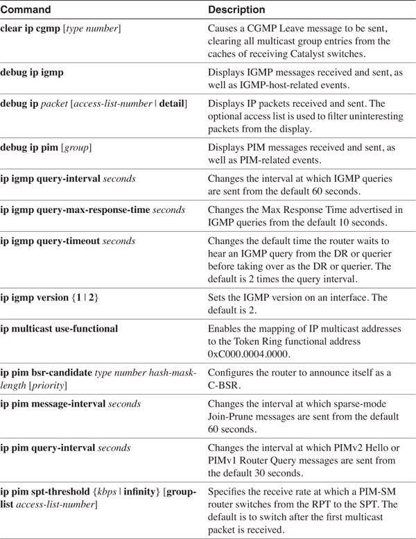

Review Questions
1 Give several reasons why replicated unicast is not a practical substitution for true multicast in a large network.
___________________________________________________________________________
___________________________________________________________________________
___________________________________________________________________________
2 What range of addresses is reserved for IP multicast?
___________________________________________________________________________
___________________________________________________________________________
___________________________________________________________________________
3 How many subnets can be created from a single Class D prefix?
___________________________________________________________________________
___________________________________________________________________________
___________________________________________________________________________
4 In what way do routers treat packets with destination addresses in the range 224.0.0.1–224.0.0.255 differently from other multicast addresses?
___________________________________________________________________________
___________________________________________________________________________
___________________________________________________________________________
5 Write the Ethernet MAC addresses that correspond to the following IP addresses:
(a) 239.187.3.201
(b) 224.18.50.1
(c) 224.0.1.87
___________________________________________________________________________
___________________________________________________________________________
___________________________________________________________________________
6 What multicast IP address or addresses are represented by the MAC address 0100.5E06.2D54?
___________________________________________________________________________
___________________________________________________________________________
___________________________________________________________________________
7 Why is Token Ring a poor medium for delivering multicast packets?
___________________________________________________________________________
___________________________________________________________________________
___________________________________________________________________________
8 What is join latency?
___________________________________________________________________________
___________________________________________________________________________
___________________________________________________________________________
9 What is leave latency?
___________________________________________________________________________
___________________________________________________________________________
___________________________________________________________________________
10 What is a multicast DR (or querier)?
___________________________________________________________________________
___________________________________________________________________________
___________________________________________________________________________
11 What device sends IGMP Query messages?
___________________________________________________________________________
___________________________________________________________________________
___________________________________________________________________________
12 What device sends IGMP Membership Report messages?
___________________________________________________________________________
___________________________________________________________________________
___________________________________________________________________________
13 How is an IGMP Membership Report message used?
___________________________________________________________________________
___________________________________________________________________________
___________________________________________________________________________
14 What is the functional difference between a General IGMP Query and a Group-Specific IGMP Query?
___________________________________________________________________________
___________________________________________________________________________
___________________________________________________________________________
15 Is IGMPv2 compatible with IGMPv1?
___________________________________________________________________________
___________________________________________________________________________
___________________________________________________________________________
16 What IP protocol number signifies IGMP?
___________________________________________________________________________
___________________________________________________________________________
___________________________________________________________________________
17 What is the purpose of the Cisco Group Membership Protocol (CGMP)?
___________________________________________________________________________
___________________________________________________________________________
___________________________________________________________________________
18 What is the advantage of using IP Snooping rather than CGMP? What is the possible disadvantage?
___________________________________________________________________________
___________________________________________________________________________
___________________________________________________________________________
19 What devices send CGMP messages: routers, Ethernet switches, or both?
___________________________________________________________________________
___________________________________________________________________________
___________________________________________________________________________
20 What is Reverse Path Forwarding?
___________________________________________________________________________
___________________________________________________________________________
___________________________________________________________________________
21 How many hosts constitute a dense topology, and how many hosts constitute a sparse topology?
___________________________________________________________________________
___________________________________________________________________________
___________________________________________________________________________
22 What is the primary advantage of explicit joins over implicit joins?
___________________________________________________________________________
___________________________________________________________________________
___________________________________________________________________________
23 What is the primary structural difference between a source-based multicast tree and a shared multicast tree?
___________________________________________________________________________
___________________________________________________________________________
___________________________________________________________________________
24 What is multicast scoping?
___________________________________________________________________________
___________________________________________________________________________
___________________________________________________________________________
25 What are the two methods of IP multicast scoping?
___________________________________________________________________________
___________________________________________________________________________
___________________________________________________________________________
26 From the perspective of a multicast router, what is meant by upstream and what is meant by downstream?
___________________________________________________________________________
___________________________________________________________________________
___________________________________________________________________________
27 What is an RPF check?
___________________________________________________________________________
___________________________________________________________________________
___________________________________________________________________________
28 What is a prune? What is a graft?
___________________________________________________________________________
___________________________________________________________________________
___________________________________________________________________________
29 What is a prune lifetime? What happens when a prune lifetime expires?
___________________________________________________________________________
___________________________________________________________________________
___________________________________________________________________________
30 What is a route dependency? How does DVMRP signal a route dependency?
___________________________________________________________________________
___________________________________________________________________________
___________________________________________________________________________
31 Is DVMRP a dense-mode protocol or a sparse-mode protocol?
___________________________________________________________________________
___________________________________________________________________________
___________________________________________________________________________
32 Is MOSPF a dense-mode protocol or a sparse-mode protocol?
___________________________________________________________________________
___________________________________________________________________________
___________________________________________________________________________
33 What is the name and type number of the LSA used exclusively by MOSPF?
___________________________________________________________________________
___________________________________________________________________________
___________________________________________________________________________
34 Can an MOSPF router establish an adjacency with an OSPF router that does not support MOSPF?
___________________________________________________________________________
___________________________________________________________________________
___________________________________________________________________________
35 Define the following MOSPF router types:
(a) Interarea multicast forwarder
(b) Inter-AS multicast forwarder
(c) Wildcard multicast receiver
___________________________________________________________________________
___________________________________________________________________________
___________________________________________________________________________
36 Is CBT a dense-mode protocol or a sparse-mode protocol?
___________________________________________________________________________
___________________________________________________________________________
___________________________________________________________________________
37 What are a CBT parent router and a CBT child router?
___________________________________________________________________________
___________________________________________________________________________
___________________________________________________________________________
38 Describe the two ways a CBT DR can deliver packets from a source to the core and the circumstances under which each method is used.
___________________________________________________________________________
___________________________________________________________________________
___________________________________________________________________________
39 What is a PIM prune override?
___________________________________________________________________________
___________________________________________________________________________
___________________________________________________________________________
40 What is a PIM forwarder? How is a forwarder selected?
___________________________________________________________________________
___________________________________________________________________________
___________________________________________________________________________
41 What criteria does PIM use to select a DR?
___________________________________________________________________________
___________________________________________________________________________
___________________________________________________________________________
42 What is a PIM SPT? What is a PIM RPT?
___________________________________________________________________________
___________________________________________________________________________
___________________________________________________________________________
43 What two mechanisms are available for Cisco routers to automatically discover PIM-SM RPs?
___________________________________________________________________________
___________________________________________________________________________
___________________________________________________________________________
44 Of the mechanisms in Question 43, which should be used in multivendor router topologies?
___________________________________________________________________________
___________________________________________________________________________
___________________________________________________________________________
45 What is a C-RP?
___________________________________________________________________________
___________________________________________________________________________
___________________________________________________________________________
46 What is a BSR?
___________________________________________________________________________
___________________________________________________________________________
___________________________________________________________________________
47 What is an RP mapping agent?
___________________________________________________________________________
___________________________________________________________________________
___________________________________________________________________________
48 What is the difference between an (S, G) mroute entry and a (*, G) mroute entry?
___________________________________________________________________________
___________________________________________________________________________
___________________________________________________________________________
49 What is the major drawback with a bidirectional CBT tree between the source and core, as opposed to a PIM-SM unidirectional tree from the RP to the source?
___________________________________________________________________________
___________________________________________________________________________
___________________________________________________________________________
50 What is PIM-SM source registration?
___________________________________________________________________________
___________________________________________________________________________
___________________________________________________________________________
51 When does a Cisco router switch from a PIM-SM RPT to an SPT?
___________________________________________________________________________
___________________________________________________________________________
___________________________________________________________________________