Chapter 7. Large-Scale IP Multicast Routing
• Multicast Scoping—This section examines the reasons for limiting the scope of IP multicast traffic, and the implementation of the two methods for multicast scoping: TTL scoping and administrative scoping.
• Case Study: Multicasting Across Non-Multicast Domains—This case study introduces techniques for passing IP multicast traffic across routers that do not support IP multicast.
• Connecting to DVMRP Networks—This section demonstrates strategies for connecting Cisco routers to DVMRP networks, and what parts of DVMRP are and are not supported by Cisco IOS Software.
• Inter-AS Multicasting—This section introduces the issues and problems specific to routing IP multicast traffic between autonomous systems and discusses the operation of MBGP and MSDP as solutions to some of the problems.
• Case Study: Configuring MBGP—This case study demonstrates the configuration of Multiprotocol BGP.
• Case Study: Configuring MSDP—This case study demonstrates the configuration of MSDP.
• Case Study: MSDP Mesh Groups—This case study demonstrates the configuration of MSDP mesh groups.
• Case Study: Anycast RP—This case study demonstrates the configuration of Anycast RP.
• Case Study: MSDP Default Peers—This case study demonstrates the configuration of MSDP default peers.
The preceding two chapters explained the present state of IP multicast routing protocols and the basics of configuring Cisco IOS Software for multicast routing. As with unicast protocols, however, you must take additional measures as your multicast domain grows to maintain stability, scalability, and controllability. This chapter examines some of the techniques and protocols available to you to accomplish those objectives.
Multicast Scoping
A primary consideration when working with large-scale multicast domains is controlling the scope of the domain. You have read the discussion of the subject in Chapter 5, "Introduction to IP Multicast Routing," and you know that there are two methods of scoping multicast domains:
• TTL scoping
• Administrative scoping
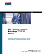
With TTL scoping, the TTL value of multicast packets is set in such a way that the packets can travel only a certain distance before the TTL is decremented to 0 and the packet is discarded. You can add some granularity to this rough method by setting boundaries on interfaces with the ip multicast ttl-threshold command. For example, an interface might be configured with ip multicast ttl-threshold 5. Only packets with TTL values greater than 5 are forwarded out of this interface. Any packets with TTL values of 5 or below are dropped. Table 7-1 shows an example of TTL scoping values. The values in this table, which is a repeat of Table 5-6, are a set of TTL values suggested for use with the MBone.
In Chapter 6, "Configuring and Troubleshooting IP Multicast Routing," you encountered several commands, such as the commands for enabling Auto-RP candidate RPs and mapping agents, that enable you to set the TTL values of the protocol messages for TTL scoping. You will encounter more commands in this chapter with the same option. However, you saw in Chapter 5 that TTL scoping lacks flexibility—a TTL boundary at an interface applies to all multicast packets. This is fine for an absolute boundary, but at times you will want some packets to be blocked and others to be forwarded.
Table 7-1 MBone TTL Thresholds
For this purpose, administrative scoping provides much more flexibility. Administrative scoping is just a procedure in which the multicast group address range 224.0.0.0–239.255.255.255 is partitioned in such a way that certain ranges of addresses are assigned certain scopes. Various domain boundaries can then be created by filtering on these address ranges. Administrative scoping is the subject of RFC 23651, and Table 7-2 shows the partitions that RFC suggests. You have already seen how the link-local scope of 224.0.0.0/24 is used. Packets with multicast addresses in this range—such as IGMP (224.0.0.1 and 224.0.0.2), OSPF (224.0.0.5 and 224.0.0.6), EIGRP (224.0.0.10), and PIM (224.0.0.13)—are never forwarded by a router and thus are restricted to the scope of the data link on which they were originated.
Table 7-2 RFC 2365 Administrative Partitions

Adding the ip multicast boundary command to an interface creates an administrative boundary. The command just references an IP access list, which specifies the group address range to be permitted or denied at the interface, as demonstrated in Example 7-1.
Example 7-1 Adding the ip multicast boundary Command to an Interface Creates an Administrative Boundary
interface Ethernet0
ip address 10.1.2.3 255.255.255.0
ip multicast boundary 10
!
interface Ethernet1
ip address 10.83.15.5 255.255.255.0
ip multicast boundary 20
!
access-list 10 deny 239.192.0.0 0.3.255.255
access-list 10 permit 224.0.0.0 15.255.255.255
access-list 20 permit 239.135.0.0 0.0.255.255
access-list 20 deny 224.0.0.0 15.255.255.255
Interface E0 marks a boundary at which organization-local packets, as defined in Table 7-2, are blocked, while global-scoped packets are passed. The boundary at E1 permits packets whose destination addresses fall within the 239.135.0.0/16 range and denies all other multicast packets. This address range falls within an undefined range in Table 7-2 and therefore has been given some special meaning by the local network administrator.
Case Study: Multicasting Across Non-Multicast Domains
One challenge you will face is connecting diverse multicast domains across domains in which multicast is not supported. This may certainly be the case when multicasting is required in only certain areas of a large routing domain. You would not want to enable multicast on every router in the unicast domain just to provide connectivity to a relatively small number of multicast routers. A second and very common example is connecting multicast domains across the decidedly unicast Internet.
In Figure 7-1, two PIM domains are separated by a unicast-only IP domain. The unicast domain might be the backbone of an enterprise network, or it might be the Internet itself. The important point is that the two multicast domains must have connectivity across it. The solution is a simple one: Create a tunnel between the two routers that can carry the PIM traffic.

Figure 7-1 PIM Domains Separated by a Unicast-Only IP Domain
Example 7-2 shows the tunnel configurations of the two routers depicted in Figure 7-1.
Example 7-2 Configuring Godzilla and Mothra to Provide Connectivity Between the Multicast Domains Through the Unicast-Only Domain
Godzillainterface Tunnel0
ip unnumbered Ethernet0
ip pim sparse-dense-mode
tunnel source Ethernet0
tunnel destination 10.224.6.2
!
interface Ethernet0
ip address 10.224.1.2 255.255.255.0
!
interface Serial0.407 point-to-point
description PVC to R7
ip address 192.168.50.1 255.255.255.0
ip pim sparse-dense-mode
frame-relay interface-dlci 407
!
router ospf 1
passive-interface Tunnel0
network 10.0.0.0 0.255.255.255 area 0
network 192.168.0.0 0.0.255.255 area 0
!
ip mroute 172.16.0.0 255.255.0.0 Tunnel0
_______________________________________________________________________
Mothrainterface Tunnel0
ip unnumbered Ethernet0
ip pim sparse-dense-mode
tunnel source Ethernet0
tunnel destination 10.224.1.2
!
interface Ethernet0
ip address 10.224.6.2 255.255.255.0
!
interface Serial1.506 point-to-point
description PVC to R6
ip address 172.16.35.1 255.255.255.0
ip pim sparse-dense-mode
frame-relay interface-dlci 506
!
router ospf 1
passive-interface Tunnel0
network 0.0.0.0 255.255.255.255 area 0
!
ip mroute 192.168.0.0 255.255.0.0 Tunnel0
You already have seen a tunnel used in Chapter 6 to provide for load sharing across equal-cost paths. The configuration here is similar. The tunnel source is the Ethernet interface on each router, but PIM is not configured on that physical interface—only on the tunnel. GRE encapsulation, the default tunnel mode, is used. OSPF is configured to run passively on TU0 to ensure that no unicast traffic traverses the tunnel. Finally, static multicast routes are configured, referencing all possible source addresses from the opposite domain and showing their upstream interface as TU0. Recall from Chapter 6 that this route is necessary to prevent RPF failures. Without it, RPF checks would use the OSPF routes and determine the upstream interface to be the routers’ E0 interfaces. As a result, all packets arriving on TU0 would fail the RPF check.
Note
If the DVMRP routers do not support GRE encapsulation, you can use IP-in-IP.
Example 7-3 shows the results of the configuration.
Example 7-3 A PIM Adjacency Is Formed Across the GRE Tunnel

Connecting to DVMRP Networks
You might, on occasion, have to connect your PIM router to a DVMRP router. This is not necessarily a large-scale multicast issue—routers that can speak only DVMRP can be encountered in an internetwork of any size. However, the most likely circumstance is when you are connecting to the MBone.
When you configure an interface on a Cisco router to run PIM, it listens for DVMRP Probe messages. When Probes are heard, as demonstrated in the output in Example 7-4, Cisco IOS Software automatically enables DVMRP on the interface. No special configuration is required. PIM routes are advertised to the DVMRP neighbor in DVMRP Report messages. DVMRP Report messages learned from the neighbor are kept in a separate DVMRP routing table shown in Example 7-5, but it is still PIM on the Cisco router that makes the multicast forwarding decisions. DVMRP Graft messages are sent and received normally, but it is the handling of Prunes and Probes that makes the Cisco IOS Software implementation of DVMRP different from a full implementation.
Example 7-4 This Router Is Receiving DVMRP Probe Messages on Interface E0 from Neighbor 10.224.1.1
Godzilla#debug ip dvmrp detail
DVMRP debugging is on
Godzilla#
DVMRP: Received Probe on Ethernet0 from 10.224.1.1
DVMRP: Aging routes, 0 entries expired
DVMRP: Received Probe on Ethernet0 from 10.224.1.1
DVMRP: Aging routes, 0 entries expired
DVMRP: Received Probe on Ethernet0 from 10.224.1.1
DVMRP: Aging routes, 0 entries expired
Example 7-5 The show ip dvmrp route Command Displays DVMRPSpecific Route Information
Godzilla#show ip dvmrp route
DVMRP Routing Table - 7 entries
10.224.2.0/24 [0/1] uptime 00:04:21, expires 00:02:38
via 10.224.1.1, Ethernet0, [version mrouted 3.255] [flags: GPM]
10.224.3.0/24 [0/1] uptime 00:04:21, expires 00:02:38
via 10.224.1.1, Ethernet0, [version mrouted 3.255] [flags: GPM]
10.224.4.0/24 [0/1] uptime 00:04:21, expires 00:02:38
via 10.224.1.1, Ethernet0, [version mrouted 3.255] [flags: GPM]
10.224.5.0/24 [0/1] uptime 00:04:21, expires 00:02:38
via 10.224.1.1, Ethernet0, [version mrouted 3.255] [flags: GPM]
10.224.6.0/24 [0/1] uptime 00:04:21, expires 00:02:38
via 10.224.1.1, Ethernet0, [version mrouted 3.255] [flags: GPM]
172.16.70.0/24 [0/1] uptime 00:04:21, expires 00:02:38
via 10.224.1.1, Ethernet0, [version mrouted 3.255] [flags: GPM]
192.168.50.0/24 [0/1] uptime 00:04:21, expires 00:02:38
via 10.224.1.1, Ethernet0, [version mrouted 3.255] [flags: GPM]
The first difference between a full implementation of DVMRP and a Cisco IOS Software-based implementation of DVMRP is the handling of Probes. As already mentioned, the detection of Probe messages is how a Cisco router discovers DVMRP neighbors. Suppose, however, that the DVMRP neighbor is on a multiaccess network, and more than one Cisco router is attached to the same network. If one of the Cisco routers were to originate a Probe, the neighboring Cisco routers would mistakenly assume the originator is a DVMRP router rather than a PIM router, as illustrated by Figure 7-2. Therefore, Cisco routers listen for Probe messages but do not originate them.
Figure 7-2 If the Top Cisco Router Were to Generate a DVMRP Probe Message, the Bottom Cisco Router Would Mistakenly Record the Originator as a DVMRP Neighbor; Therefore, Cisco Routers Do Not Generate DVMRP Probes
The second difference is the handling of Prune messages. Recall from the DVMRP discussion in Chapter 5 that a DVMRP router is required to maintain state for each downstream neighbor. If a downstream neighbor sends a Prune message, only that neighbor’s state is pruned. Traffic is still forwarded on the interface unless all DVMRP neighbors send a Prune. This addresses the situation in which there are multiple downstream neighbors on a multiaccess network, and it prevents a Prune from one neighbor causing an unwanted Prune from another neighbor.
Note
Also recall from Chapter 5 that PIM-DM uses a Prune override mechanism to address this problem, instead of requiring the maintenance of neighbor states.
However, Cisco routers do not maintain DVMRP neighbor state. Therefore, to avoid the problem of one downstream neighbor’s Prunes pruning traffic needed by another downstream neighbor, Cisco routers ignore DVMRP Prune messages received on multiaccess interfaces. On point-to-point interfaces, Prunes are received and processed normally, because by definition there can be only one downstream neighbor. Cisco routers send Prune messages normally on both multiaccess and point-to-point interfaces on which there are DVMRP neighbors.
The difficulty, as this approach stands, should be apparent to you. If DVMRP routers connected across a multiaccess network to upstream Cisco routers cannot prune themselves, the Cisco routers forward unwanted multicast traffic into the DVMRP domain. The solution to the difficulty is, once again, tunnels.
In Figure 7-3, a Cisco router is connected to two DVMRP routers across a multiaccess network. By creating tunnels to each of the DVMRP routers, Cisco IOS Software sees the DVMRP neighbors as connected via point-to-point links rather than a multiaccess link. The Cisco router then accepts prunes.

Figure 7-3 Tunnels Are Used to Create Point-to-Point Connections to the DVMRP Routers Across the Multiaccess Network, so DVMRP Pruning Works Correctly
Example 7-6 shows the configuration for the Cisco router in Figure 7-3.
Example 7-6 Configuring the Cisco Router in Figure 7-3 to Accept Prunes via Point-to-Point Links
interface Tunnel0
ip unnumbered Ethernet0
ip pim sparse-dense-mode
tunnel source Ethernet0
tunnel destination 10.1.1.2
tunnel mode dvmrp
!
interface Tunnel1
no ip address
ip pim sparse-dense-mode
tunnel source Ethernet0
tunnel destination 10.1.1.4
tunnel mode dvmrp
!
interface Ethernet0
ip address 10.1.1.1 255.255.255.0
The only significant difference from the earlier tunnel configurations you have seen is that the tunnel mode is set to DVMRP rather than the default GRE. As with the earlier tunnel configurations, PIM is configured on the tunnels but not on the physical interface. If there were also Cisco PIM routers on the multiaccess network, just configure PIM on the Ethernet interface so that the DVMRP routers connect over the tunnels and the PIM routers connect over the Ethernet.
Note
Remember that if multicast sources are reachable via the DVMRP routers, you must configure static mroutes to avoid RPF failures.
Inter-AS Multicasting
A challenge facing any multicast routing protocol (or any unicast routing protocol, for that matter) is scaling efficiently to the set of hosts requiring delivery of packets. You have seen how dense mode protocols such as PIM-DM and DVMRP do not scale well; by definition, the protocols assume that most hosts in the multicast domain are group members. PIM-SM, being a sparse mode protocol, scales better because it assumes most hosts in the multicast domain are not group members. Yet the assumption of both dense mode and sparse mode protocols is that they span a single domain. In other words, all the IP multicast routing protocols you have examined so far can be considered multicast IGPs.
How, then, can multicast packets be delivered across AS boundaries while maintaining the autonomy of each AS?
The PIM-SM Internet Draft begins to address the issue by defining a PIM Multicast Border Router (PMBR). The PMBR resides at the edge of a PIM domain and builds special branches to all RPs in the domain, as illustrated in Figure 7-4. Each branch is represented by a (*,*, RP) entry, where the two wildcard components represent all source and group addresses that map to that RP. When an RP receives traffic from a source, it forwards the traffic to the PMBR, which then forwards the traffic into the neighboring domain. The PMBR depends on the neighboring domain to send it prunes for any unwanted traffic, and the PMBR then sends prunes to the RP.
Figure 7-4 A PIM Multicast Border Router Forms Multicast Branches to Each RP in Its Domain Called (*, *, RP) Branches. RPs Forward All Source Traffic to the PMBR Along These Branches
The shortcoming of the PMBR concept is this flood-and-prune behavior. In fact, PMBRs were proposed primarily to connect PIM-SM domains to DVMRP domains. Because of the poor scalability inherent in the approach, Cisco IOS Software does not support PMBRs.
Accepting that PIM-SM is the de facto standard IP multicast routing protocol, the question of how to route multicast traffic between autonomous systems can be reduced to a question of how to route between PIM-SM domains. Two issues must be addressed:
• When a source is in one domain and group members are in other domains, RPF procedures must remain valid.
• To preserve autonomy, a domain cannot rely on an RP in another domain.
PIM-SM is protocol-independent, so the first issue seems easy enough to resolve. Just as PIM uses the unicast IGP routes to determine RPF interfaces within a domain, it can use BGP routes to determine RPF interfaces to sources in other autonomous systems. When moving traffic between domains, however, you may want your multicast traffic to use different links from your unicast traffic, as shown in Figure 7-5. If a multicast packet arrives on link A, and BGP indicates that the unicast route to the packet’s source is via link B, the RPF check fails. Static mroutes could be used to prevent RPF problems, but they are obviously not practical on a large scale. Instead, BGP must be extended so that it can indicate whether an advertised prefix is to be used for unicast routing, multicast RPF checks, or both.

Figure 7-5 Inter-AS Traffic Engineering Requirements May Dictate That Multicast Traffic Pass Over a Link Separate from Unicast Traffic
As it happens, PIM can take advantage of existing extensions to BGP. The extended version of BGP is called Multiprotocol BGP (MBGP) and is described in RFC 2283.2 Although the extensions were created to allow BGP to carry reachability information for protocols such as IPv6 and IPX, the widespread application of MBGP is to advertise multicast sources. As a result, the "M" in MBGP is frequently and inaccurately thought to represent "multicast" rather than "multiprotocol."
The most common application of MBGP is for peer connections at NAPs among service providers that have agreed to exchange multicast traffic. As Figure 7-6 shows, the autonomous systems may be peered for unicast traffic but must share a separate peering point for multicast traffic. Some prefixes will be advertised over both the unicast and multicast NAPs, so MBGP is used to differentiate multicast RPF paths from unicast paths.

Figure 7-6 MBGP Is Used When Separate Peering Points Are Required for Multicast and Unicast
The second inter-AS PIM issue (to preserve autonomy, a domain cannot rely on an RP in another domain) stems from the fact that an AS does not want to depend on an RP that it does not control. If each AS places its own RPs, however, there must be a protocol that each RP can use to share its source information with other RPs across AS boundaries and in turn discover sources known by other RPs, as illustrated in Figure 7-7. That protocol is the Multicast Source Discovery Protocol (MSDP).3

Figure 7-7 Multicast Source Discovery Protocol Is Spoken Between RPs and Allows Each RP to Discover Sources Known by Other RPs
The following two sections describe the MBGP extensions and the operation of MSDP.
Multiprotocol Extensions for BGP (MBGP)
RFC 2283 extends BGP for multiprotocol support by defining two new attributes:
• Multiprotocol Reachable NLRI, or MP_REACH_NLRI (type 14)
• Multiprotocol Unreachable NLRI, or MP_UNREACH_NLRI (type 15)
Both attributes are optional, nontransitive. Recall from Chapter 2, "Introduction to Border Gateway Protocol 4," that this means BGP speakers are not required to support the attributes, and BGP speakers that do not support the attributes do not pass them to their peers.
The MP_REACH_NLRI attribute advertises feasible routes, and MP_UNREACH_NLRI withdraws feasible routes. The Network Layer Reachability Information (NLRI) contained in the attributes is the protocol-specific destination information. When MBGP is used for IP multicast, the NLRI is always an IPv4 prefix describing one or more multicast sources. Remember that PIM routers do not use this information for packet forwarding but only for determining the RPF interface toward a particular source. These two new attributes provide the capability of signaling to a BGP peer whether a particular prefix is to be used for unicast routing, multicast RPF, or both.
The MP_REACH_NLRI consists of one or more [Address Family Information, Next Hop Information, NLRI] triples. The MP_UNREACH_NLRI consists of one or more [Address Family Information, Unfeasible Routes Length, Withdrawn Routes] triples.
Note
The complete format of the MP_REACH_NLRI is more complicated than is indicated here—some fields are irrelevant to IP multicast. For a complete description, see RFC 2283.
The Address Family Information consists of an Address Family Identifier (AFI) and a Subsequent AFI (Sub-AFI). The AFI for IPv4 is 1, so it is always set to 1 for IP multicast.
The sub-AFI describes whether the NLRI is to be used for unicast routing only, multicast RPF information only, or both, as documented in Table 7-3.
Table 7-3 Subsequent Address Family Identifiers

Operation of Multicast Source Discovery Protocol (MSDP)
The purpose of MSDP is, as the name states, to discover multicast sources in other PIM domains. The advantage of running MSDP is that your own RPs exchange source information with RPs in other domains; your group members do not have to be directly dependent on another domain’s RP.
Note
You will see in some subsequent case studies how MSDP can prove useful for sharing source information within a single domain, too.
MSDP uses TCP (port 639) for its peering connections. As with BGP, using point-to-point TCP peering means that each peer must be explicitly configured. When a PIM DR registers a source with its RP as illustrated in Figure 7-8, the RP sends a Source Active (SA) message to all of its MSDP peers.
Figure 7-8 RPs Advertise Sources to Their MSDP Neighbors with Source Active Messages
The SA contains the following:
• The address of the multicast source
• The group address to which the source is sending
• The IP address of the originating RP
Each MSDP peer that receives the SA floods the SA to all of its own peers downstream from the originator. In some cases, such as the RPs in AS 6 and AS 7 of Figure 7-8, an RP may receive a copy of an SA from more than one MSDP peer. To prevent looping, the RP consults the BGP next-hop database to determine the next hop toward the SA’s originator. If both MBGP and unicast BGP are configured, MBGP is checked first, and then unicast BGP. That next-hop neighbor is the RPF peer for the originator, and SAs received from the originator on any interface other than the interface to the RPF peer are dropped. The SA flooding process is, therefore, called peer RPF flooding. Because of the peer RPF flooding mechanism, BGP or MBGP must be running in conjunction with MSDP.
When an RP receives an SA, it checks to see whether there are any members of the SA’s group in its domain by checking to see whether there are interfaces on the group’s (*, G) outgoing interface list. If there are no group members, the RP does nothing. If there are group members, the RP sends an (S, G) join toward the source. As a result, a branch of the source tree is constructed across AS boundaries to the RP. As multicast packets arrive at the RP, they are forwarded down its own shared tree to the group members in the RP’s domain. The members’ DRs then have the option of joining the RPT tree to the source using standard PIM-SM procedures.
The originating RP continues to send periodic SAs for the (S, G) every 60 seconds for as long as the source is sending packets to the group. When an RP receives an SA, it has the option to cache the message. Suppose, for example, that an RP receives an SA for (172.16.5.4, 228.1.2.3) from originating RP 10.5.4.3. The RP consults its mroute table and finds that there are no active members for group 228.1.2.3, so it passes the SA message to its peers downstream of 10.5.4.3 without caching the message. If a host in the domain then sends a join to the RP for group 228.1.2.3, the RP adds the interface toward the host to the outgoing interface list of its (*, 224.1.2.3) entry. Because the previous SA was not cached, however, the RP has no knowledge of the source. Therefore, the RP must wait until the next SA message is received before it can initiate a join to the source.
If, on the other hand, the RP is caching SAs, the router will have an entry for (172.16.5.4, 228.1.2.3) and can join the source tree as soon as a host requests a join. The trade-off here is that in exchange for reducing the join latency, memory is consumed caching SA messages that may or may not be needed. If the RP belongs to a very large MSDP mesh, and there are large numbers of SAs, the memory consumption can be significant.
By default, Cisco IOS Software does not cache SAs. You can enable caching with the command ip msdp cache-sa-state. To help alleviate possible memory stress, you can link the command to an extended access list that specifies what (S, G) pairs to cache.
If an RP has an MSDP peer that is caching SAs, you can reduce the join latency at the RP without turning on caching by using SA Request and SA Response messages. When a host requests a join to a particular group, the RP sends an SA Request message to its caching peer(s). If a peer has cached source information for the group in question, it sends the information to the requesting RP with an SA Response message. The requesting RP uses the information in the SA Response but does not forward the message to any other peers. If a noncaching RP receives an SA Request, it sends an error message back to the requestor.
To enable a Cisco router to send SA Request messages, use the ip msdp sa-request command to specify the IP address or name of a caching peer. You can use the command multiple times to specify multiple caching peers.
MSDP Message Formats
MSDP messages are carried in TCP segments. When two routers are configured as MSDP peers, the router with the higher IP address listens on TCP port 639, and the router with the lower IP address attempts an active connect to port 639.
The MSDP messages use a TLV (Type/Length/Value) format and may be one of five types, shown in Table 7-4. The following sections detail the format of each message type.

Source Active TLV
When an MSDP RP receives a PIM Register message from an IP multicast source, it sends a Source Active message to its peers. Figure 7-9 shows the MSDP Source Active TLV format. SA messages are subsequently sent every 60 seconds until the source is no longer active. Multiple (S, G) entries can be advertised by a single SA.
Figure 7-9 The MSDP Source Active TLV Format
The fields for the MSDP Source Active TLV format are defined as follows:
• Entry Count specifies the number of (S, G) entries being advertised by the specified RP address.
• RP Address is the IP address of the originating RP.
• Reserved is set to all zeroes.
• Sprefix Length specifies the prefix length of the associated source address. This length is always 32.
• Group Address is the multicast IP address to which the associated source is sending multicast packets.
• Source Address is the IP address of the active source.
Source Active Request TLV
SA Request Messages, the format of which is shown in Figure 7-10, are used to request (S, G) information from MSPD peers that are caching SA state. SA Request messages should be sent only to caching peers (noncaching peers will return an error notification) and are sent only by RPs that are explicitly configured to do so.

Figure 7-10 The MSDP Source Active Request TLV Format
The fields for the MSDP Source Active Request TLV format are defined as follows:
• Gprefix Length specifies the length of the group address prefix.
• Group Address Prefix specifies the group address for which source information is requested.
Source Active Response TLV
SA Response messages, the format of which is shown in Figure 7-11, are sent by a caching peer in response to an SA Request message. They provide the requesting peer the source address and RP address associated with the specified group address. The format is the same as the SA message.

Figure 7-11 The MSPD Source Active Response TLV Format
Keepalive TLV
The active side (the peer with the lower IP address) of an MSDP connection tracks the passive side of the connection with a 75-second Keepalive timer. If no MSDP message is received from the passive side before the Keepalive timer expires, the active peer resets the TCP connection. If an MSDP message is received, the timer is reset. If the passive peer has no other MSDP messages to send, it sends a Keepalive message to prevent the active peer from resetting the connection. As Figure 7-12 shows, the Keepalive message is a simple 24-bit TLV consisting of a type and length field.

Figure 7-12 The MSDP Keepalive TLV Format
Notification TLV
A Notification message is sent when an error is detected. Figure 7-13 shows the Notification message format.

Figure 7-13 The MSDP Notification TLV Format
The fields for the MSDP Notification TLV format are defined as follows:
• Length = x + 5 is the length of the TLV, where x is the length of the data field and 5 is the first 5 octets.
• O is the open bit. If this bit is cleared, the connection must be closed upon receipt of the Notification. Table 7-5 shows the states of the O bit for different error subcodes. MC indicates must close; the O bit is always cleared. CC indicates can close; the O bit might be cleared.
• Error code is a 7-bit unsigned integer indicating the Notification type. Table 7-5 lists the error codes.
• Error Subcode is an 8-bit unsigned integer that may offer more details about the error code. If the error code has no subcode, this field is zero. Table 7-5 shows the possible error subcodes associated with the error codes.
• Data is a variable-length field containing information specific to the error code and error subcode. The various data fields are not covered in this chapter; see the MSDP Internet Draft for more information on the possible contents of this field.
Table 7-5 MSDP Error Codes and Subcodes

Case Study: Configuring MBGP
Figure 7-14 depicts three autonomous systems. AS 200 is advertising unicast prefixes 172.16.226.0/24 and 172.16.227.0/24 to transit AS 100 and is used for normal inter-AS routing. AS 200 also has several multicast sources. These are hosts at 172.16.224.1 and 172.16.225.50. Additionally, several multicast sources are on subnet 172.16.227.0/24, and that prefix is advertised not only as a unicast prefix but also as a multicast source prefix.
Figure 7-14 AS 200 Is Advertising Several Prefixes and Addresses; Some Are Unicast, Some Are Multicast, and One Is Both
Example 7-7 shows the configurations of Gorgo and Rodan in Figure 7-14.
Example 7-7 The MBGP Configurations of Gorgo and Rodan in Figure 7-14
Gorgorouter bgp 200Rodan
no synchronization
network 172.16.226.0 mask 255.255.255.0
network 172.16.227.0 mask 255.255.255.0
neighbor 192.168.1.2 remote-as 100
no auto-summary
!
address-family ipv4 multicast
neighbor 192.168.1.2 activate
network 172.16.224.1 mask 255.255.255.255
network 172.16.225.50 mask 255.255.255.255
network 172.16.227.0 mask 255.255.255.0
exit-address-family
_______________________________________________________________________router bgp 100
no synchronization
neighbor 192.168.1.1 remote-as 200
neighbor 192.168.254.2 remote-as 100
neighbor 192.168.254.2 update-source Loopback0
neighbor 192.168.254.2 next-hop-self
!
address-family ipv4 multicast
neighbor 192.168.1.1 activate
neighbor 192.168.254.2 activate
neighbor 192.168.254.2 next-hop-self
exit-address-family
The unicast portion of both routers’ BGP configurations is no different from the configurations you observed in Chapter 3, "Configuring and Troubleshooting Border Gateway Protocol 4." Neighbors and their AS numbers are identified, as are the two unicast prefixes that Gorgo is to advertise into AS 100.
Note
This chapter assumes you are already familiar with unicast BGP configuration. If some of the IBGP tools such as next-hop-self and update-source are not clear to you, you are encouraged to review Chapter 3.
MBGP is activated with the address-family ipv4 multicast command. Recall from the section "Multiprotocol Extensions for BGP (MBGP)" that MBGP uses two new route attributes—MP_REACH_NLRI and MP_UNREACH_NLRI—and that the attributes’ Address Family Indicator (AFI) code for IPv4 is 1. The multicast keyword sets the attributes’ Sub-AFI to multicast. Following the address-family command, MBGP is configured very similarly to unicast BGP. MBGP neighbors are identified, and the prefixes to be advertised as multicast are identified. The activate keyword is used to show that MBGP is to be activated for that neighbor. The peer’s AS number is specified only under BGP, not MBGP. Notice that IBGP configurations, such as next-hop-self, are used under MBGP just as they are with BGP. You also can configure policies separately for MBGP neighbors. The final command, exit-address-family, is entered automatically by Cisco IOS Software to mark the end of the MBGP configuration stanzas.
Enabling address-family ipv4 multicast implicitly enables the address-family ipv4 unicast command. Although the command is never displayed in the configuration, it is applied to the unicast BGP configuration. Its result is that the prefixes specified under that configuration section are given the MP_REACH_NLRI attribute and are assigned a unicast Sub-AFI. Notice that the prefix 172.16.227.0/24 appears in Gorgo’s configuration under both BGP and MBGP. This prefix is then advertised as both unicast and multicast (Sub-AFI = 3).
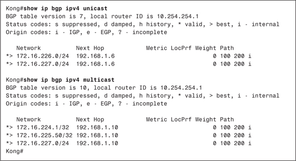
In Example 7-8, the show ip bgp ipv4 command is used to show the results of the configurations. First the unicast keyword is used, and then the multicast keyword is used, and the prefixes whose Sub-AFI matches the keyword are displayed. Notice again that 172.16.227.0/24 is included in both displays because it has been configured as both a unicast and a multicast prefix.
Note
The output of show ip bgp ipv4 unicast is the same as the output of show ip bgp.
Example 7-8 The show ip bgp ipv4 Command Displays Prefixes According to Their Sub-AFI Values

The configurations of Megalon and Kong from Figure 7-14 are a bit more complicated, because separate links are used for unicast BGP and for MBGP. Example 7-9 shows the configurations for these two routers.
Example 7-9 Configuring Megalon and Kong to Use Separate Data Links for Multicast and Unicast
Megalonrouter bgp 100
no synchronization
no bgp default ipv4-unicast
neighbor 192.168.1.5 remote-as 300
neighbor 192.168.1.5 activate
neighbor 192.168.1.9 remote-as 300
neighbor 192.168.254.1 remote-as 100
neighbor 192.168.254.1 update-source Loopback0
neighbor 192.168.254.1 activate
neighbor 192.168.254.1 next-hop-self
no auto-summary
!
address-family ipv4 multicast
neighbor 192.168.1.9 activate
neighbor 192.168.254.1 activate
exit-address-family
_______________________________________________________________________
Kongrouter bgp 300
no synchronization
no bgp default ipv4-unicast
neighbor 192.168.1.6 remote-as 100
neighbor 192.168.1.6 activate
neighbor 192.168.1.10 remote-as 100
no auto-summary
!
address-family ipv4 multicast
neighbor 192.168.1.10 activate
exit-address-family
The MBGP configurations show that only the 192.168.1.8/30 subnet is used for MBGP peering, and there are some new commands under the unicast BGP section. Remember that when the address-family ipv4 multicast command is invoked, the address-family ipv4 unicast command is invoked automatically and implicitly. In the case of subnet 192.168.1.8/30, unicast BGP traffic is unwanted. Therefore, the command no ip default ipv4-unicast is used to prevent this automatic behavior. Then, the neighbor activate command is used to explicitly enable unicast BGP on the desired links. Notice that the 192.168.2.1/30 and 192.168.1.4/30 subnets are activated for unicast, but the 192.168.1.8/30 subnet is not. This link has only the AS number specified under BGP so that peering can occur.
Example 7-10 shows the results of the configurations in Example 7-9. The output here looks similar to that in Example 7-8, in that the unicast and multicast prefixes are correctly classified. In this case, however, the next-hop address of the unicast prefixes is 192.168.1.6, and the next-hop address (RPF neighbor) of the multicast prefixes is 192.168.1.10.
Example 7-10 AS 300 Has Received the Prefixes Advertised by AS 200, Using the Correct Next-Hop Addresses for the Unicast-Only and Multicast-Only Links Between Kong and Megalon
Example 7-11 shows the practical application of BGP versus MBGP advertisements. Using the 172.16.227.0/24 prefix, which is advertised both as unicast and multicast, a route lookup is performed for 172.16.227.1. The display shows that the route carries a next-hop address of 192.168.1.6, which is the unicast-only link in Figure 7-14. Next, an RPF lookup is performed on the same address. That lookup returns a next-hop address of 192.168.1.10, the multicast-only link. So the same address references two different links, depending on the function for which the address is being used.
Example 7-11 An IP Route Lookup for 172.16.227.1 Shows the Next Hop to Be 192.168.1.6, but an RPF Lookup of the Same Address Shows a Next Hop of 192.168.1.10
Kong#show ip route 172.16.227.1
Routing entry for 172.16.227.0/24
Known via "bgp 300", distance 20, metric 0
Tag 100, type external
Last update from 192.168.1.6 04:10:21 ago
Routing Descriptor Blocks:
* 192.168.1.6, from 192.168.1.6, 04:10:21 ago
Route metric is 0, traffic share count is 1
AS Hops 2
Kong#show ip rpf 172.16.227.1
RPF information for ? (172.16.227.1)
RPF interface: Serial1
RPF neighbor: ? (192.168.1.10)
RPF route/mask: 172.16.227.0/24
RPF type: mbgp
RPF recursion count: 0
Doing distance-preferred lookups across tables
Kong#
It is worth emphasizing one last time that MBGP does not affect the forwarding of multicast traffic. Further configuration is needed in a situation such as the parallel links depicted in Figure 7-14 to force multicast traffic over the multicast-only link. MBGP just allows the dissemination of RPF information across AS boundaries.
Case Study: Configuring MSDP
Figure 7-15 again shows the routers from the preceding case study. Here, the four routers are also RPs for their respective autonomous systems, and the illustration shows their RP addresses.
Figure 7-15 MSDP Sessions Are Configured Between the Four RPs
MSDP is enabled quite simply with the command ip msdp peer, specifying the peer’s IP address. Example 7-12 shows the MSDP configurations for the four routers in Figure 7-15.
Example 7-12 Configuring MSDP Sessions Between the Four RPs in Figure 7-15
Gorgoip msdp peer 192.168.1.2Kong
_______________________________________________________________________ip msdp peer 192.168.1.10Rodan
_______________________________________________________________________ip msdp peer 192.168.1.1Megalon
ip msdp peer 192.168.254.2 connect-source Loopback0
_______________________________________________________________________ip msdp peer 192.168.254.1 connect-source Loopback0
ip msdp peer 192.168.1.9
The peering between Gorgo and Rodan, and between Kong and Megalon, is quite straightforward. Each has only a single link over which to peer, so the session is configured between the two physical interface addresses. Between Rodan and Megalon, however, the peering is between loopback addresses. As with IBGP peering, MSDP sessions between loopback interfaces provide more resiliency. If the link shown between Rodan and Megalon in Figure 7-15 should fail, and if there is another path between the routers (not shown in the illustration), the TCP session can be rerouted. By default, the source address of the TCP packets carrying the MSDP session is the address of the originating physical interface. For peering to an address that is not part of a directly connected subnet, the connect-source option is used to change the default source address.
Example 7-13 displays the status of Megalon’s two MSDP sessions using the show ip msdp peer command. Such expected information as the state of the connection, uptime, and messages sent/received appears.
Example 7-13 The show ip msdp peer Command Displays the Status of MSDP Peering Sessions
Megalon#show ip msdp peer
MSDP Peer 192.168.254.1 (?), AS 100
Description:
Connection status:
State: Up, Resets: 0, Connection source: Loopback0 (192.168.254.2)
Uptime(Downtime): 3d22h, Messages sent/received: 5683/5677
Output messages discarded: 0
Connection and counters cleared 3d22h ago
SA Filtering:
Input filter: none, route-map: none
Output filter: none, route-map: none
SA-Requests:
Input filter: none
Sending SA-Requests to peer: disabled
Peer ttl threshold: 0
Input queue size: 0, Output queue size: 0
MSDP Peer 192.168.1.9 (?), AS 300
Description:
Connection status:
State: Up, Resets: 0, Connection source: none configured
Uptime(Downtime): 3d22h, Messages sent/received: 5674/5694
Output messages discarded: 0
Connection and counters cleared 3d22h ago
SA Filtering:
Input filter: none, route-map: none
Output filter: none, route-map: none
SA-Requests:
Input filter: none
Sending SA-Requests to peer: disabled
Peer ttl threshold: 0
Input queue size: 0, Output queue size: 0
Megalon#
Example 7-13 also shows fields for displaying filters that might have been configured for SA and SA Request messages. You have several options for filtering at an MSDP router to control and scope MSDP activity. You can do the following:
• Control the local sources that are allowed to register with the RP.
• Control the SA messages the RP sends to and receives from its MSDP peers.
• Control the SA Request messages the RP sends to and receives from its peers.
Other options for larger-scale MSDP environments are the addition of descriptions for each peer and configurable TTL values for the MSDP messages. Example 7-14 shows a more elaborate configuration for router Megalon in Figure 7-15.
Note
The configuration shown here is for demonstration purposes only. No argument is made as to the practicality of the configuration.
Example 7-14 A More-Complex MSDP Configuration
ip pim rp-address 192.168.254.2
ip msdp peer 192.168.254.1 connect-source Loopback0
ip msdp description 192.168.254.1 Rodan in AS 100
ip msdp sa-filter out 192.168.254.1 list 101
ip msdp filter-sa-request 192.168.254.1 list 1
ip msdp sa-request 192.168.254.1
ip msdp ttl-threshold 192.168.254.1 5
ip msdp peer 192.168.1.9
ip msdp description 192.168.1.9 Kong in AS 300
ip msdp sa-filter in 192.168.1.9 list 101
ip msdp sa-filter out 192.168.1.9 list 103
ip msdp sa-request 192.168.1.9
ip msdp ttl-threshold 192.168.1.9 2
ip msdp cache-sa-state list 101
ip msdp redistribute list 102
!
access-list 1 permit 229.50.0.0 0.0.255.255
access-list 101 permit ip 10.254.0.0 0.0.255.255 224.0.0.0 31.255.255.255
access-list 102 permit ip 192.168.224.0 0.0.0.255 224.0.0.0 31.255.255.255
access-list 103 permit ip 172.16.0.0 0.0.255.255 230.0.0.0 0.255.255.255
access-list 103 permit ip 192.168.224.0 0.0.0.255 224.0.0.0 31.255.255.255
The two statements enabling MSDP to Rodan and Kong, as shown in Example 7-12, remain. But added to the configuration is a text description for each peer, using the ip msdp description command. The description always appears directly after the ip msdp peer command for a specific peer, and it is obviously useful when there are large numbers of MSDP peers.
SA caching is enabled with ip msdp cache-sa-state, and in this configuration, an optional access list is referenced. Access list 101 specifies that Megalon will cache only SA messages for (S, G) pairs whose source address begins with 10.254.0.0/16. The group can be any multicast address (224.0.0.0/3).
An ip msdp sa-request statement is entered for each of the two peers to further reduce join latency. If the router receives a join message for a particular group, it sends an SA Request message to the two neighbors. The assumption here, as previously discussed, is that the two neighbors are configured to cache SA messages.
SA Requests to Rodan (192.168.254.1) are further restricted with the ip msdp filter-sa-request command. This filter references access list 1, which allows only 229.50.0.0/16. The result is that Megalon will request only source information from Rodan for groups whose addresses fall under prefix 229.50.0.0/16.
Next, Megalon is configured to send only SA messages for a subset of the possible sources that might send PIM-SM Register messages to it. The ip msdp redistribute statement references access list 102, which in turn permits source prefixes of 192.168.224.0/24 and group address prefixes of 224.0.0.0/3 (all multicast groups). Any source can still register with the RP, within the limits of the RP’s PIM-SM configuration, but only those sources whose first 24 address bits are 192.168.224 are advertised in SA messages.
The forwarding of SA messages to MSDP peers is regulated with the ip msdp sa-filter out command. This filter applies to all SA messages, whether locally originated or received from another MSDP peer, whereas the ip msdp redistribute command applies only to locally originated SA messages. Megalon has two of these statements. For neighbor Rodan (192.168.254.1), only messages from source prefix 10.254.0.0/16 are forwarded, as specified by access list 101. Megalon sends to Kong (192.168.1.9) only SA messages that are permitted by access list 103. This access list permits messages whose source prefix is 172.16.0.0/16 and whose group addresses belong to 230.0.0.0/8, or sources whose prefix is 192.168.224.0/24 originating packets for any multicast group.
You can also filter incoming SA messages with the ip msdp sa-filter in command. Using this command, Megalon accepts SA messages from Kong only if the (S, G) pair is permitted by access list 101. Notice that this is the same constraint that is placed on outgoing SA messages to Rodan.
Finally, the TTL values of the MSDP messages are regulated with the ip msdp ttl-threshold command. The TTL of messages sent to Rodan is set to 5, whereas the TTL of messages sent to Kong is set to 2.
Example 7-15 shows the results of this configuration. Compare this display with the display in Example 7-13, and you can see the descriptions, filters, and TTL thresholds that have changed.
Example 7-15 This Display Reflects the Changes Made to Megalon’s MSDP Configuration
Megalon#show ip msdp peer
MSDP Peer 192.168.254.1 (?), AS 100
Description: Rodan in AS 100
Connection status:
State: Up, Resets: 0, Connection source: Loopback0 (192.168.254.2)
Uptime(Downtime): 4d14h, Messages sent/received: 6624/6617
Output messages discarded: 0
Connection and counters cleared 4d14h ago
SA Filtering:
Input filter: none, route-map: none
Output filter: 101, route-map: none
SA-Requests:
Input filter: 1
Sending SA-Requests to peer: enabled
Peer ttl threshold: 5
Input queue size: 0, Output queue size: 0
MSDP Peer 192.168.1.9 (?), AS 300
Description: Kong in AS 300
Connection status:
State: Up, Resets: 0, Connection source: none configured
Uptime(Downtime): 4d14h, Messages sent/received: 6614/6634
Output messages discarded: 0
Connection and counters cleared 4d14h ago
SA Filtering:
Input filter: 101, route-map: none
Output filter: 102, route-map: none
SA-Requests:
Input filter: none
Sending SA-Requests to peer: enabled
Peer ttl threshold: 2
Input queue size: 0, Output queue size: 0
Megalon#
In addition to access lists, you can link incoming and outgoing SA filters to route maps for even better granularity of control and application of policy. You also can use route maps in conjunction with MSDP redistribution, as well as AS path access lists.
Case Study: MSDP Mesh Groups
In the preceding case study, routers Rodan and Megalon are RPs in the same AS. Large multicast domains can frequently have many RPs to share the workload or to localize multicast trees. Although MSPD has been presented so far as a tool for sharing inter-AS source information, it also proves useful when there are multiple RPs in a single domain, and sources always register to certain RPs but members throughout the domain must find any source.
Every RP in the domain commonly has an MSDP peering session to every other RP in the domain, for redundancy and robustness. Figure 7-16 shows an example. The four RPs in the illustration are in the same AS, and each is peered to the other three. The four routers may or may not be directly connected and are probably physically remote from each other.

Figure 7-16 A Full MSDP Mesh Exists Between These Four Routers
Example 7-16 shows the configurations of the four routers in Figure 7-16.
Example 7-16 Configuring MSDP on the Four Routers in Figure 7-16
Frankensteinip pim rp-address 10.100.1.1Wolfman
ip msdp peer 10.100.1.3 connect-source Loopback0
ip msdp description 10.100.1.3 to Mummy
ip msdp peer 10.100.1.2 connect-source Loopback0
ip msdp description 10.100.1.2 to Wolfman
ip msdp peer 10.100.1.4 connect-source Loopback0
ip msdp description 10.100.1.4 to Dracula
_______________________________________________________________________ip pim rp-address 10.100.1.2Mummy
ip msdp peer 10.100.1.1 connect-source Loopback0
ip msdp description 10.100.1.1 to Frankenstein
ip msdp peer 10.100.1.3 connect-source Loopback0
ip msdp description 10.100.1.3 to Mummy
ip msdp peer 10.100.1.4 connect-source Loopback0
ip msdp description 10.100.1.4 to Dracula
_______________________________________________________________________ip pim rp-address 10.100.1.3Dracula
ip msdp peer 10.100.1.1 connect-source Loopback0
ip msdp description 10.100.1.1 to Frankenstein
ip msdp peer 10.100.1.2 connect-source Loopback0
ip msdp description 10.100.1.2 to Wolfman
ip msdp peer 10.100.1.4 connect-source Loopback0
ip msdp description 10.100.1.4 to Dracula
_______________________________________________________________________ip pim rp-address 10.100.1.4
ip msdp peer 10.100.1.1 connect-source Loopback0
ip msdp description 10.100.1.1 to Frankenstein
ip msdp peer 10.100.1.2 connect-source Loopback0
ip msdp description 10.100.1.2 to Wolfman
ip msdp peer 10.100.1.3 connect-source Loopback0
ip msdp description 10.100.1.3 to Mummy
The problem with the configuration as it stands is that an SA message generated by one router is flooded by all the other routers, causing large numbers of peer RPF flooding failures and resulting MSDP notification messages. If every RP has an MSDP connection to every other RP, however, no flooding is necessary. Every RP receives a copy of every SA directly from the originator. To remedy the flooding problem, an MSDP mesh group is built.
An MSDP mesh group is a set of fully meshed MSDP peers such as the ones shown in Figure 7-16, but no transiting of SA messages takes place. That is, when an RP receives an SA from a peer, it does not forward the message to any other peer.
Mesh groups are configured with the ip msdp mesh-group command. The group is given an arbitrary name (so that one RP can belong to more than one mesh group, if necessary), and the members of the mesh group are specified. The configurations in Example 7-17 add the RPs in Figure 7-16 to a mesh group named Boogeymen.
Example 7-17 Adding the RPs in Figure 7-16 to Mesh Group Boogeymen
Frankensteinip pim rp-address 10.100.1.1Wolfman
ip msdp peer 10.100.1.3 connect-source Loopback0
ip msdp description 10.100.1.3 to Mummy
ip msdp peer 10.100.1.2 connect-source Loopback0
ip msdp description 10.100.1.2 to Wolfman
ip msdp peer 10.100.1.4 connect-source Loopback0
ip msdp description 10.100.1.4 to Dracula
ip msdp mesh-group Boogeymen 10.100.1.3
ip msdp mesh-group Boogeymen 10.100.1.2
ip msdp mesh-group Boogeymen 10.100.1.4
_______________________________________________________________________ip pim rp-address 10.100.1.2Mummy
ip msdp peer 10.100.1.1 connect-source Loopback0
ip msdp description 10.100.1.1 to Frankenstein
ip msdp peer 10.100.1.3 connect-source Loopback0
ip msdp description 10.100.1.3 to Mummy
ip msdp peer 10.100.1.4 connect-source Loopback0
ip msdp description 10.100.1.4 to Dracula
ip msdp mesh-group Boogeymen 10.100.1.1
ip msdp mesh-group Boogeymen 10.100.1.3
ip msdp mesh-group Boogeymen 10.100.1.4
_______________________________________________________________________ip pim rp-address 10.100.1.3Dracula
ip msdp peer 10.100.1.1 connect-source Loopback0
ip msdp description 10.100.1.1 to Frankenstein
ip msdp peer 10.100.1.2 connect-source Loopback0
ip msdp description 10.100.1.2 to Wolfman
ip msdp peer 10.100.1.4 connect-source Loopback0
ip msdp description 10.100.1.4 to Dracula
ip msdp mesh-group Boogeymen 10.100.1.1
ip msdp mesh-group Boogeymen 10.100.1.2
ip msdp mesh-group Boogeymen 10.100.1.4
_______________________________________________________________________ip pim rp-address 10.100.1.4
ip msdp peer 10.100.1.1 connect-source Loopback0
ip msdp description 10.100.1.1 to Frankenstein
ip msdp peer 10.100.1.2 connect-source Loopback0
ip msdp description 10.100.1.2 to Wolfman
ip msdp peer 10.100.1.3 connect-source Loopback0
ip msdp description 10.100.1.3 to Mummy
ip msdp mesh-group Boogeymen 10.100.1.1
ip msdp mesh-group Boogeymen 10.100.1.2
ip msdp mesh-group Boogeymen 10.100.1.3
Case Study: Anycast RP
Designers of large, geographically diverse PIM-SM domains must often wrestle with the dilemma of where to most efficiently place the RPs. PIM-SM allows only a single group-to-RP mapping, which presents several problems in large domains:4
• Possible traffic bottlenecks
• Lack of scalable register decapsulation (when using shared trees)
• Slow failover when an active RP fails
• Possible suboptimal forwarding of multicast packets
• Dependence on remote RPs
You read in Chapters 5 and 6 about different schemes for alleviating some of these problems, such as the hashing algorithm used with the PIMv2 bootstrap protocol and Auto-RP filtering. None of these tools offer a completely acceptable solution. Anycast RP is a method of allowing the mapping of a single group to multiple RPs. The RPs can be distributed throughout the domain, and all use the same RP address. As a result, a "virtual RP" is created. MSDP is fundamental to the creation of a virtual RP.
Note
Generically, anycasting means that packets can be sent to a single address, and one of several devices can respond to the address.
Figure 7-17 shows an example where the same routers from the preceding case study are used, but all four routers are running Auto-RP and are announcing an RP address of 10.100.254.1. Source DRs within the domain know of just the one RP address and register with the closest physical RP. Normally, this causes partitioning of the PIM domain. Using an MSDP mesh group, however, the anycast RPs can exchange source information within the group.
Figure 7-17 The Four Routers Form a Virtual RP, Announcing a Single RP Address of 10.100.254.1, and Using MSDP to Exchange Information About Sources That Have Registered to Each Router
The unicast routing protocol of each anycast RP advertises the common RP address. From the perspective of source and group DRs, there is just a single RP at this address, with several routes to it. A DR chooses the shortest route, which in reality leads to the nearest anycast RP. If the anycast RP fails, the unicast protocol announces the route to the RP as unfeasible. The DR sees only the unfeasible route and chooses the next-best route, which in reality leads to the next-nearest anycast RP. As a result, RP failover is linked to and almost as fast as the unicast reconvergence time.
The MSDP peering takes place as before, between the LO0 interfaces; however, another loopback interface is used to configure the RP address that the routers announce. Normally, MSDP uses the RP address in its SA messages. Because all four routers are announcing the same RP address, MSDP must be configured to use a unique address in its SA messages. The ip msdp originator-id command accomplishes this. Example 7-18 shows the relevant configurations of the four routers, using mesh groups and ip msdp originator-id.
Example 7-18 Configuring Frankenstein, Wolfman, Mummy, and Dracula for Anycast RP
Frankensteininterface Loopback0Wolfman
ip address 10.100.1.1 255.255.255.255
!
interface Loopback5
ip address 10.100.254.1 255.255.255.255
ip pim sparse-dense-mode
!
router ospf 1
router-id 10.100.1.1
network 0.0.0.0 255.255.255.255 area 0
!
router bgp 6500
bgp router-id 10.100.1.1
neighbor Boogeymen peer-group
neighbor Boogeymen remote-as 6500
neighbor Boogeymen update-source Loopback0
neighbor 10.100.1.2 peer-group Boogeymen
neighbor 10.100.1.3 peer-group Boogeymen
neighbor 10.100.1.4 peer-group Boogeymen
!
address-family ipv4 multicast
neighbor 10.100.1.2 activate
neighbor 10.100.1.3 activate
neighbor 10.100.1.4 activate
exit-address-family
!
ip pim send-rp-announce Loopback5 scope 20
ip pim send-rp-discovery Loopback5 scope 20
ip msdp peer 10.100.1.3 connect-source Loopback0
ip msdp description 10.100.1.3 to Mummy
ip msdp peer 10.100.1.2 connect-source Loopback0
ip msdp description 10.100.1.2 to Wolfman
ip msdp peer 10.100.1.4 connect-source Loopback0
ip msdp description 10.100.1.4 to Dracula
ip msdp mesh-group Boogeymen 10.100.1.3
ip msdp mesh-group Boogeymen 10.100.1.2
ip msdp mesh-group Boogeymen 10.100.1.4
ip msdp cache-sa-state
ip msdp originator-id Loopback0
_______________________________________________________________________interface Loopback0Mummy
ip address 10.100.1.2 255.255.255.255
!
interface Loopback5
ip address 10.100.254.1 255.255.255.255
ip pim sparse-dense-mode
!
router ospf 1
router-id 10.100.1.2
network 0.0.0.0 255.255.255.255 area 0
!
router bgp 6500
bgp router-id 10.100.1.2
neighbor Boogeymen peer-group
neighbor Boogeymen remote-as 6500
neighbor Boogeymen update-source Loopback0
neighbor 10.100.1.1 peer-group Boogeymen
neighbor 10.100.1.3 peer-group Boogeymen
neighbor 10.100.1.4 peer-group Boogeymen
!
address-family ipv4 multicast
neighbor 10.100.1.1 activate
neighbor 10.100.1.3 activate
neighbor 10.100.1.4 activate
exit-address-family
!
ip pim send-rp-announce Loopback5 scope 20
ip pim send-rp-discovery Loopback5 scope 20
ip msdp peer 10.100.1.1 connect-source Loopback0
ip msdp description 10.100.1.1 to Frankenstein
ip msdp peer 10.100.1.3 connect-source Loopback0
ip msdp description 10.100.1.3 to Mummy
ip msdp peer 10.100.1.4 connect-source Loopback0
ip msdp description 10.100.1.4 to Dracula
ip msdp mesh-group Boogeymen 10.100.1.1
ip msdp mesh-group Boogeymen 10.100.1.3
ip msdp mesh-group Boogeymen 10.100.1.4
ip msdp cache-sa-state
ip msdp originator-id Loopback0
_______________________________________________________________________interface Loopback0Dracula
ip address 10.100.1.3 255.255.255.255
!
interface Loopback5
ip address 10.100.254.1 255.255.255.255
ip pim sparse-dense-mode
!
router ospf 1
router-id 10.100.1.3
network 0.0.0.0 255.255.255.255 area 0
!
router bgp 6500
bgp router-id 10.100.1.3
neighbor Boogeymen peer-group
neighbor Boogeymen remote-as 6500
neighbor Boogeymen update-source Loopback0
neighbor 10.100.1.1 peer-group Boogeymen
neighbor 10.100.1.2 peer-group Boogeymen
neighbor 10.100.1.4 peer-group Boogeymen
!
address-family ipv4 multicast
neighbor 10.100.1.1 activate
neighbor 10.100.1.2 activate
neighbor 10.100.1.4 activate
exit-address-family
ip pim send-rp-announce Loopback5 scope 20
ip pim send-rp-discovery Loopback5 scope 20
ip msdp peer 10.100.1.1 connect-source Loopback0
ip msdp description 10.100.1.1 to Frankenstein
ip msdp peer 10.100.1.2 connect-source Loopback0
ip msdp description 10.100.1.2 to Wolfman
ip msdp peer 10.100.1.4 connect-source Loopback0
ip msdp description 10.100.1.4 to Dracula
ip msdp mesh-group Boogeymen 10.100.1.1
ip msdp mesh-group Boogeymen 10.100.1.2
ip msdp mesh-group Boogeymen 10.100.1.4
ip msdp cache-sa-state
ip msdp originator-id Loopback0
_______________________________________________________________________interface Loopback0
ip address 10.100.1.4 255.255.255.255
!
interface Loopback5
ip address 10.100.254.1 255.255.255.255
ip pim sparse-dense-mode
!
router ospf 1
router-id 10.100.1.4
network 0.0.0.0 255.255.255.255 area 0
!
router bgp 6500
bgp router-id 10.100.1.4
neighbor Boogeymen peer-group
neighbor Boogeymen remote-as 6500
neighbor Boogeymen update-source Loopback0
neighbor 10.100.1.1 peer-group Boogeymen
neighbor 10.100.1.2 peer-group Boogeymen
neighbor 10.100.1.3 peer-group Boogeymen
!
address-family ipv4 multicast
neighbor 10.100.1.1 activate
neighbor 10.100.1.2 activate
neighbor 10.100.1.3 activate
exit-address-family
!
ip pim send-rp-announce Loopback5 scope 20
ip pim send-rp-discovery Loopback5 scope 20
ip msdp peer 10.100.1.1 connect-source Loopback0
ip msdp description 10.100.1.1 to Frankenstein
ip msdp peer 10.100.1.2 connect-source Loopback0
ip msdp description 10.100.1.2 to Wolfman
ip msdp peer 10.100.1.3 connect-source Loopback0
ip msdp description 10.100.1.3 to Mummy
ip msdp mesh-group Boogeymen 10.100.1.1
ip msdp mesh-group Boogeymen 10.100.1.2
ip msdp mesh-group Boogeymen 10.100.1.3
ip msdp cache-sa-state
ip msdp originator-id Loopback0
In Example 7-18, each of the four routers is configured as both an Auto-RP candidate RP and a mapping agent. You also can use static mapping or PIMv2 bootstrap with anycast RP. All four routers in this example are configured to cache SA messages.
Interface LO5 is used on each router to configure the virtual RP address, whereas LO0 is the endpoint of the MSDP sessions. Notice in the configurations that the Auto-RP commands reference LO5, whereas the ip msdp originator-id command references LO0. This is vital, because MSDP must have unique IP addresses at the endpoints of its peering sessions.
The OSPF and BGP stanzas are shown for an important reason. Recall that OSPF and BGP use the highest IP address configured on any loopback interface as its router ID. Unfortunately, the IP address on LO5 is higher on each router than the IP address on LO0. As a result, the OSPF and BGP processes on each router would by default use a router ID of 10.100.254.1. One of many undesirable results would be the thrashing of the OSPF databases as each router’s LSAs try to override the other routers’ LSAs. One solution is to always use a virtual RP address that is numerically lower than any other loopback address, but there are obvious impracticalities in this and some large vulnerabilities to inadvertent configuration mistakes. A better solution, used in this example, is to force each router to use its unique LO0 address with the router-id statement under the OSPF and BGP configurations.
Notice also that the LO0 interfaces are not running PIM. These interfaces are unnecessary to PIM functionality, and serve only to provide router-specific IP addresses for MSDP peering.
Case Study: MSDP Default Peers
If an AS is a stub or nontransit AS, and particularly if the AS is not multihomed, there is little or no reason to run BGP to its transit AS. A static default route at the stub AS, and a static route pointing to the stub prefixes at the transit AS, is generally sufficient. But what if the stub AS is also a multicast domain and its RP must peer with an RP in the neighboring domain? The overview of the MSDP operation explained that MSDP depends on the BGP next-hop database for its peer RPF checks.
You can disable this dependency on BGP with the ip msdp default-peer command. MSDP just accepts all SA messages from default peers. Figure 7-18 shows a simple example. Here, the stub AS is peered to the transit AS by a single link. RPF checks are not necessary, because there is only one path and therefore no possibility of loops.
Figure 7-18 BGP Is Typically Not Run Between a Stub AS and Its Transit AS, but This Can Cause a Problem for MSDP
Example 7-19 shows the MSDP configuration of the two routers.
Example 7-19 MSDP Configurations for Routers Jason and Freddy
Jasonip msdp peer 172.16.224.1 connect-source Loopback0Freddy
ip msdp default-peer 172.16.224.1
_______________________________________________________________________ip msdp peer 192.168.1.1 connect-source Loopback0
ip msdp default-peer 192.168.1.1
A stub AS also might want to have MSDP peering with more than one RP for the sake of redundancy, as shown in Figure 7-19. SA messages cannot just be accepted from both default peers, because there is no RPF check mechanism. Instead, SA messages are accepted from only one peer. If that peer fails, messages are then accepted from the other peer. The underlying assumption here, of course, is that both default peers are sending the same SA messages.

Figure 7-19 Jason Is Connected to More Than One Default MSDP Peer
Example 7-20 shows the configuration for Jason.
Example 7-20 Configuring Jason to Have Redundant Peering with Both Freddy and Norman
ip msdp peer 172.16.224.1 connect-source Loopback0
ip msdp peer 172.16.224.2 connect-source Loopback0
ip msdp default-peer 172.16.224.1
ip msdp default-peer 172.16.224.2
Under normal circumstances, the active default peer is the first peer in the configuration—in this case, 172.16.224.1. SAs are not accepted from 172.16.224.2 unless 172.16.224.1 fails.
The RP in a transit AS is likely to have more than one default MSDP peer, as shown in Figure 7-20. Just listing the default peers, as was shown in the preceding example, does not work, because SAs would be accepted by only a single peer. To cause the RP to accept SA messages from multiple peers while still providing loop avoidance in the absence of a peer RPF check, BGP-style prefix lists are used. The RP then accepts SA messages from all of its default peers, but only for source prefixes allowed by each peer’s associated prefix list. The underlying assumption here is that each AS is using distinct prefixes, so loop avoidance is ensured.
Figure 7-20 The RP in the Transit AS Has Three Default MSDP Peers
Example 7-21 shows the configuration for Freddy.
Example 7-21 Configuring an RP to Accept SA Messages from Multiple Peers
ip msdp peer 192.168.1.1 connect-source Loopback0
ip msdp peer 192.168.2.1 connect-source Loopback0
ip msdp peer 192.168.3.1 connect-source Loopback0
ip msdp default-peer 192.168.1.1 prefix-list AS1
ip msdp default-peer 192.168.2.1 prefix-list AS2
ip msdp default-peer 192.168.3.1 prefix-list AS3
!
ip prefix-list AS1 seq 5 permit 192.168.1.0/24 le 32
ip prefix-list AS2 seq 5 permit 192.168.2.0/24 le 32
ip prefix-list AS3 seq 5 permit 192.168.3.0/24 le 32
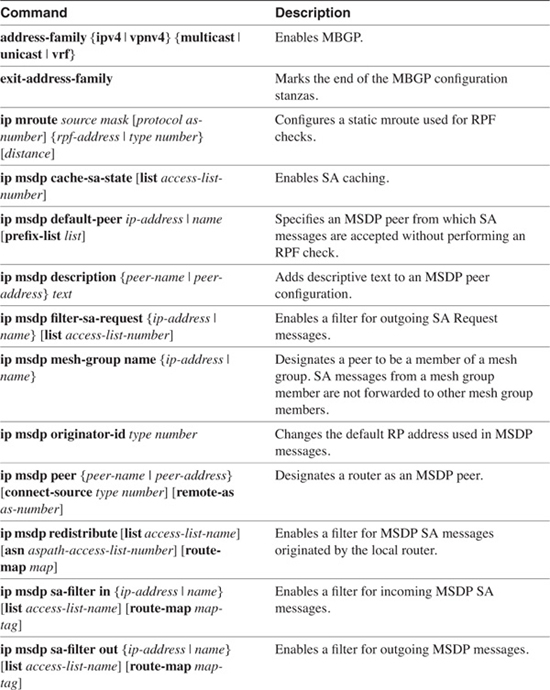
Command Summary
Table 7-6 lists and describes the commands discussed in this chapter.

End Notes
1David Meyer, "RFC 2365: Administratively Scoped IP Multicast," (Work in Progress).
2Tony Bates, Ravi Chandra, Dave Katz, and Yakov Rekhter, "RFC 2283: Multiprotocol Extensions for BGP-4," (Work in Progress).
3Dino Farinacci et al., "Multicast Source Discovery Protocol (MSDP)," draft-ietf-msdp-spec-05.txt, February, 2000.
4Dorain Kim, David Meyer, Henry Kilmer, and Dino Farinacci, "Anycast RP Mechanism Using PIM and MSDP," draft-ietf-mboned-anycast-rp-05.txt, January, 2000.
Looking Ahead
You have, at this point, invested a sizeable portion of your time to learning not only the ins and outs of IP routing, but also the problems presented by the growing complexity of routing in modern IP networks. Many of the solutions to these problems involve working with (or around) the limitations of IPv4 and its associated routing protocols. The next chapter shows how the newest version of the IP protocol, IPv6, has been created with the lessons of IPv4 firmly in mind. When most people think of IPv6, they think primarily of 128-bit addresses and the alleviation of the IPv4 addressing limitations. As you will see, however, IPv6 is much more. It is designed for better security, better inter-AS qualities, and better support for multicasting, while at the same time eliminating many of the unnecessary complexities of IPv4.
Review Questions
1 In the section "Multicast Scoping," a sample configuration is given for administrative scoping. The boundary at interface E0 blocks organization-local packets (destination addresses whose prefixes match 239.192.0.0/14) but passes packets with global scope. Will a packet with a group address 224.0.0.50 pass this boundary?
___________________________________________________________________________
___________________________________________________________________________
___________________________________________________________________________
2 How does Cisco IOS Software handle DVMRP Prune messages on point-to-point and multiaccess interfaces that are configured to run PIM?
___________________________________________________________________________
___________________________________________________________________________
___________________________________________________________________________
3 Why does Cisco IOS Software accept DVMRP Probe messages, but does not send them?
___________________________________________________________________________
___________________________________________________________________________
___________________________________________________________________________
4 What is a PIM (*,*, RP) entry?
___________________________________________________________________________
___________________________________________________________________________
___________________________________________________________________________
5 How does Multiprotocol BGP (MBGP) differ from normal BGP?
___________________________________________________________________________
___________________________________________________________________________
___________________________________________________________________________
6 What is the MBGP AFI?
___________________________________________________________________________
___________________________________________________________________________
___________________________________________________________________________
7 Is the following statement true or false? MSDP carries information about multicast sources and group members between RPs in different PIM domains.
___________________________________________________________________________
___________________________________________________________________________
___________________________________________________________________________
8 What is the transport protocol for MSDP?
___________________________________________________________________________
___________________________________________________________________________
___________________________________________________________________________
9 What is an MSDP SA message?
___________________________________________________________________________
___________________________________________________________________________
___________________________________________________________________________
10 How does an MSDP RP determine whether an SA was received on an RPF interface?
___________________________________________________________________________
___________________________________________________________________________
___________________________________________________________________________
11 What is SA caching?
___________________________________________________________________________
___________________________________________________________________________
___________________________________________________________________________
12 Is there an alternative to reducing join latency without enabling SA caching?
___________________________________________________________________________
___________________________________________________________________________
___________________________________________________________________________