Chapter 5. Adjust and Troubleshoot Single-Area OSPF
Objectives
Upon completion of this chapter, you will be able to answer the following questions:
![]() What are the commands to modify the OSPF interface priority to influence DR/BDR election?
What are the commands to modify the OSPF interface priority to influence DR/BDR election?
![]() What are the commands to configure OSPF to propagate a default route?
What are the commands to configure OSPF to propagate a default route?
![]() What commands are available to modify OSPF interface settings to improve network performance?
What commands are available to modify OSPF interface settings to improve network performance?
![]() What are the commands to configure OSPF authentication to secure routing updates?
What are the commands to configure OSPF authentication to secure routing updates?
![]() What are the process and tools available to troubleshoot a single-area OSPF network?
What are the process and tools available to troubleshoot a single-area OSPF network?
![]() What is the process to troubleshoot missing route entries in a single-area OSPFv2 routing table?
What is the process to troubleshoot missing route entries in a single-area OSPFv2 routing table?
![]() What is the process to troubleshoot missing route entries in a single-area OSPFv3 routing table?
What is the process to troubleshoot missing route entries in a single-area OSPFv3 routing table?
Key Terms
This chapter uses the following key terms. You can find the definitions in the Glossary.
Point-to-point page 251
Broadcast multiaccess page 251
Nonbroadcast multiaccess (NBMA) page 252
Point-to-multipoint page 252
Virtual links page 253
designated router (DR) page 255
backup designated router (BDR) page 255
autonomous system boundary router (ASBR) page 268
single-homed page 268
OSPF Hello and Dead intervals page 273
MD5 authentication page 280
Introduction (5.0.1.1)
OSPF is a popular link-state routing protocol that can be fine-tuned in many ways. Some of the most common methods of fine-tuning include manipulating the Designated Router/Backup Designated Router (DR/BDR) election process, propagating default routes, fine-tuning the OSPFv2 and OSPFv3 interfaces, and enabling authentication.
This chapter of OSPF describes these tuning features, the configuration mode commands to implement these features for both IPv4 and IPv6, and the components and commands used to troubleshoot OSPFv2 and OSPFv3.
![]() Class Activity 5.0.1.2: DR and BDR Election
Class Activity 5.0.1.2: DR and BDR Election
You are trying to decide how to influence the selection of the designated router and backup designated router for your OSPF network. This activity simulates that process.
Three separate designated-router election scenarios will be presented. The focus is on electing a DR and BDR for your group. Refer to the PDF for this activity for the remaining instructions.
If additional time is available, two groups can be combined to simulate DR and BDR elections.
Advanced Single-Area OSPF Configurations (5.1)
This section assumes a certain level of expertise in basic OSPF configuration. However, it does include a brief review to help refresh the reader before proceeding to the more advanced topics of OSPF operation in multiaccess networks, default route propagation, fine-tuning OSPF interfaces, and securing OSPF routing updates.
Routing in the Distribution and Core Layers (5.1.1)
This topic briefly reviews routing concepts and single-area OSPF configuration.
Routing Versus Switching (5.1.1.1)
A scalable network requires a hierarchical network design. The focus of the preceding chapters was on the access and distribution layers. Layer 2 switches, link aggregation, LAN redundancy, and wireless LANs are all technologies that provide or enhance user access to network resources.
Scalable networks also require optimal reachability between sites. Remote network reachability is provided by routers and Layer 3 switches, which operate in the distribution and core layers, as shown in Figure 5-1.
Routers and Layer 3 switches learn about remote networks in one of two ways:
![]() Manually: Remote networks are manually entered into the route table using static routes.
Manually: Remote networks are manually entered into the route table using static routes.
![]() Dynamically: Remote routes are automatically learned using a dynamic routing protocol such as Enhanced Interior Gateway Routing Protocol (EIGRP) or Open Shortest Path First (OSPF).
Dynamically: Remote routes are automatically learned using a dynamic routing protocol such as Enhanced Interior Gateway Routing Protocol (EIGRP) or Open Shortest Path First (OSPF).
Static Routing (5.1.1.2)
The example in Figure 5-2 provides a sample scenario of static routing.

A network administrator can manually configure a static route to reach a specific network. Unlike a dynamic routing protocol, static routes are not automatically updated and must be manually reconfigured anytime the network topology changes. A static route does not change until the administrator manually reconfigures it.
Static routing has three primary uses:
![]() Providing ease of routing table maintenance in smaller networks that are not expected to grow significantly.
Providing ease of routing table maintenance in smaller networks that are not expected to grow significantly.
![]() Routing to and from stub networks. A stub network is a network accessed by a single route, and the router has only one neighbor.
Routing to and from stub networks. A stub network is a network accessed by a single route, and the router has only one neighbor.
![]() Using a single default route to represent a path to any network that does not have a more specific match with another route in the routing table. Default routes are used to send traffic to any destination beyond the next upstream router.
Using a single default route to represent a path to any network that does not have a more specific match with another route in the routing table. Default routes are used to send traffic to any destination beyond the next upstream router.
Dynamic Routing Protocols (5.1.1.3)
Routing protocols allow routers to dynamically share information about remote networks, as shown in Figure 5-3.

Routers receiving the update automatically add this information to their own routing tables. The routing protocols then determine the best path, or route, to each network. A primary benefit of dynamic routing protocols is that routers exchange routing information when there is a topology change. This exchange allows routers to automatically learn about new networks and also to find alternate paths when there is a link failure to a current network.
Compared to static routing, dynamic routing protocols require less administrative overhead. However, the expense of using dynamic routing protocols is dedicating part of a router’s resources for protocol operation, including CPU time and network link bandwidth. Despite the benefits of dynamic routing, static routing still has its place. There are times when static routing is more appropriate and other times when dynamic routing is the better choice. However, it is important to understand that static and dynamic routing are not mutually exclusive. Rather, most networks use a combination of dynamic routing protocols and static routes.
The two most common dynamic routing protocols are EIGRP and OSPF. The focus of this chapter is on OSPF.
All dynamic routing protocols are capable of advertising and propagating static routes in their routing updates.
Open Shortest Path First (5.1.1.4)
OSPF is a commonly implemented link-state routing protocol. It was developed as a replacement for the distance vector routing protocol Routing Information Protocol (RIP). However, OSPF has significant advantages over RIP in that it offers faster convergence and scales to much larger network implementations.
![]() Classless: It is classless by design; therefore, it supports VLSM and CIDR.
Classless: It is classless by design; therefore, it supports VLSM and CIDR.
![]() Efficient: Routing changes trigger routing updates (no periodic updates). It uses the SPF algorithm to choose the best path.
Efficient: Routing changes trigger routing updates (no periodic updates). It uses the SPF algorithm to choose the best path.
![]() Fast convergence: It quickly propagates network changes.
Fast convergence: It quickly propagates network changes.
![]() Scalable: It works well in small and large network sizes. Routers can be grouped into areas to support a hierarchical system.
Scalable: It works well in small and large network sizes. Routers can be grouped into areas to support a hierarchical system.
![]() Secure: It supports Message Digest 5 (MD5) authentication. When enabled, OSPF routers only accept encrypted routing updates from peers with the same preshared password.
Secure: It supports Message Digest 5 (MD5) authentication. When enabled, OSPF routers only accept encrypted routing updates from peers with the same preshared password.
Configuring Single-Area OSPF (5.1.1.5)
The focus of this chapter is to adjust and troubleshoot OSPF. However, it is a good idea to review a basic implementation of the OSPF routing protocol. Figure 5-4 displays the topology used for configuring OSPFv2.

The routers in the topology have a starting configuration, including enabled interface addresses. There is currently no static routing or dynamic routing configured on any of the routers. All interfaces on Routers R1, R2, and R3 (except the loopback on R2) are within the OSPF backbone area. The ISP router is used as the routing domain’s gateway to the Internet.
Example 5-1 shows the configuration for R1.
Example 5-1 Basic Single-Area OSPFv2 Configuration for R1
R1(config)# interface gigabitethernet 0/0
R1(config-if)# bandwidth 1000000
R1(config-if)# router ospf 10
R1(config-router)# router-id 1.1.1.1
R1(config-router)# auto-cost reference-bandwidth 1000
R1(config-router)# network 172.16.1.0 0.0.0.255 area 0
R1(config-router)# network 172.16.3.0 0.0.0.255 area 0
R1(config-router)# network 192.168.10.4 0.0.0.3 area 0
R1(config-router)# passive-interface g0/0
The Gigabit Ethernet 0/0 interface is configured to reflect its true bandwidth of 1,000,000 kilobits (that is 1,000,000,000 b/s). Next, from OSPF router configuration mode, the router ID is assigned, the reference bandwidth is adjusted to account for fast interfaces, and the three networks attached to R1 are advertised. Notice how the wildcard mask is used to identify the specific networks.
Example 5-2 shows the configuration for R2.
Example 5-2 Basic Single-Area OSPFv2 Configuration for R2
R2(config)# interface gigabitethernet 0/0
R2(config-if)# bandwidth 1000000
R2(config-if)# router ospf 10
R2(config-router)# router-id 2.2.2.2
R2(config-router)# auto-cost reference-bandwidth 1000
R2(config-router)# network 172.16.2.1 0.0.0.0 area 0
R2(config-router)# network 172.16.3.2 0.0.0.0 area 0
R2(config-router)# network 192.168.10.9 0.0.0.0 area 0
R2(config-router)# passive-interface g0/0
The Gigabit Ethernet 0/0 interface is configured to reflect its true bandwidth, the router ID is assigned, the reference bandwidth is adjusted to account for fast interfaces, and the three networks attached to R2 are advertised. Notice how the use of the wildcard mask can be avoided by identifying the actual router interface with a quad-zero mask. This effectively makes OSPF use the subnet mask assigned to the router interface as the advertised network mask.
Example 5-3 shows the configuration for R3, which is similar to R1 and R2.
Example 5-3 Basic Single-Area OSPFv2 Configuration for R3
R3(config)# interface GigabitEthernet0/0
R3(config-if)# bandwidth 1000000
R3(config-if)# router ospf 10
R3(config-router)# router-id 3.3.3.3
R3(config-router)# auto-cost reference-bandwidth 1000
R3(config-router)# network 192.168.1.1 0.0.0.0 area 0
R3(config-router)# network 192.168.10.6 0.0.0.0 area 0
R3(config-router)# network 192.168.10.10 0.0.0.0 area 0
R3(config-router)# passive-interface g0/0
R3(config-router)#
*Aug 28 17:15:26.547: %OSPF-5-ADJCHG: Process 10, Nbr 1.1.1.1 on Serial0/0/0 from
LOADING to FULL, Loading Done
*Aug 28 17:15:26.863: %OSPF-5-ADJCHG: Process 10, Nbr 2.2.2.2 on Serial0/0/1 from
LOADING to FULL, Loading Done
R3(config-router)#
Notice the informational messages displaying that R3 has established a full neighbor adjacency with R1 with router ID 1.1.1.1 and R2 with router ID 2.2.2.2. The OSPF network has converged.
Verifying Single-Area OSPF (5.1.1.6)
Useful commands to verify OSPF include the following:
![]() show ip ospf neighbor: This command verifies that the router has formed an adjacency with its neighboring routers. If the router ID of the neighboring router is not displayed, or if it does not show as being in a state of FULL, the two routers have not formed an OSPF adjacency. Example 5-4 shows output for R2.
show ip ospf neighbor: This command verifies that the router has formed an adjacency with its neighboring routers. If the router ID of the neighboring router is not displayed, or if it does not show as being in a state of FULL, the two routers have not formed an OSPF adjacency. Example 5-4 shows output for R2.
Example 5-4 show ip ospf neighbor Command
R2# show ip ospf neighbor
Neighbor ID Pri State Dead Time Address Interface
3.3.3.3 0 FULL/ - 00:00:39 192.168.10.10 Serial0/0/1
1.1.1.1 0 FULL/ - 00:00:32 172.16.3.1 Serial0/0/0
![]() show ip protocols: This command provides a quick way to verify vital OSPF configuration information. This includes the OSPF process ID, the router ID, networks the router is advertising, the neighbors the router is receiving updates from, and the default administrative distance, which is 110 for OSPF. Example 5-5 shows the output for R2.
show ip protocols: This command provides a quick way to verify vital OSPF configuration information. This includes the OSPF process ID, the router ID, networks the router is advertising, the neighbors the router is receiving updates from, and the default administrative distance, which is 110 for OSPF. Example 5-5 shows the output for R2.
Example 5-5 show ip protocols Command
R2# show ip protocols
*** IP Routing is NSF aware ***
Routing Protocol is "ospf 10"
Outgoing update filter list for all interfaces is not set
Incoming update filter list for all interfaces is not set
Router ID 2.2.2.2
Number of areas in this router is 1. 1 normal 0 stub 0 nssa
Maximum path: 4
Routing for Networks:
172.16.2.1 0.0.0.0 area 0
172.16.3.2 0.0.0.0 area 0
192.168.10.9 0.0.0.0 area 0
Passive Interface(s):
GigabitEthernet0/0
Routing Information Sources:
Gateway Distance Last Update
3.3.3.3 110 00:34:32
1.1.1.1 110 00:35:05
Distance: (default is 110)
![]() show ip ospf: This command is used to display the OSPF process ID and router ID as well as the OSPF SPF and OSPF area information. Example 5-6 shows the output for R2.
show ip ospf: This command is used to display the OSPF process ID and router ID as well as the OSPF SPF and OSPF area information. Example 5-6 shows the output for R2.
Example 5-6 show ip ospf Command
R2# show ip ospf
Routing Process "ospf 10" with ID 2.2.2.2
Start time: 01:37:24.332, Time elapsed: 01:32:17.412
Supports only single TOS(TOS0) routes
Supports opaque LSA
Supports Link-local Signaling (LLS)
Supports area transit capability
Supports NSSA (compatible with RFC 3101)
Event-log enabled, Maximum number of events: 1000, Mode: cyclic
Router is not originating router-LSAs with maximum metric
Initial SPF schedule delay 5000 msecs
Minimum hold time between two consecutive SPFs 10000 msecs
Maximum wait time between two consecutive SPFs 10000 msecs
Incremental-SPF disabled
Minimum LSA interval 5 secs
Minimum LSA arrival 1000 msecs
LSA group pacing timer 240 secs
Interface flood pacing timer 33 msecs
Retransmission pacing timer 66 msecs
Number of external LSA 0. Checksum Sum 0x000000
Number of opaque AS LSA 0. Checksum Sum 0x000000
Number of DCbitless external and opaque AS LSA 0
Number of DoNotAge external and opaque AS LSA 0
Number of areas in this router is 1. 1 normal 0 stub 0 nssa
Number of areas transit capable is 0
External flood list length 0
IETF NSF helper support enabled
Cisco NSF helper support enabled
Reference bandwidth unit is 1000 mbps
Area BACKBONE(0)
Number of interfaces in this area is 3
Area has no authentication
SPF algorithm last executed 01:30:07.268 ago
SPF algorithm executed 3 times
Area ranges are
Number of LSA 3. Checksum Sum 0x02033A
Number of opaque link LSA 0. Checksum Sum 0x000000
Number of DCbitless LSA 0
Number of indication LSA 0
Number of DoNotAge LSA 0
Flood list length 0
![]() show ip ospf interface: This command provides a detailed list for every OSPF-enabled interface and is very useful to determine whether the network statements were correctly composed. Example 5-7 shows the output for the Serial 0/0/1 interface on R2.
show ip ospf interface: This command provides a detailed list for every OSPF-enabled interface and is very useful to determine whether the network statements were correctly composed. Example 5-7 shows the output for the Serial 0/0/1 interface on R2.
Example 5-7 show ip ospf interface Command
R2# show ip ospf interface serial 0/0/1
Serial0/0/1 is up, line protocol is up
Internet Address 192.168.10.9/30, Area 0, Attached via Network Statement
Process ID 10, Router ID 2.2.2.2, Network Type POINT_TO_POINT, Cost: 976
Topology-MTID Cost Disabled Shutdown Topology Name
0 976 no no Base
Transmit Delay is 1 sec, State POINT_TO_POINT
Timer intervals configured, Hello 10, Dead 40, Wait 40, Retransmit 5
oob-resync timeout 40
Hello due in 00:00:03
Supports Link-local Signaling (LLS)
Cisco NSF helper support enabled
IETF NSF helper support enabled
Index 3/3, flood queue length 0
Next 0x0(0)/0x0(0)
Last flood scan length is 1, maximum is 1
Last flood scan time is 0 msec, maximum is 0 msec
Neighbor Count is 1, Adjacent neighbor count is 1
Adjacent with neighbor 3.3.3.3
Suppress hello for 0 neighbor(s)
![]() show ip ospf interface brief: This command is useful to display a summary and status of OSPF-enabled interfaces. Example 5-8 shows the output for R2.
show ip ospf interface brief: This command is useful to display a summary and status of OSPF-enabled interfaces. Example 5-8 shows the output for R2.
Example 5-8 show ip ospf interface brief Command
R2# show ip ospf interface brief
Interface PID Area IP Address/Mask Cost State Nbrs F/C
Gi0/0 10 0 172.16.2.1/24 1 DR 0/0
Se0/0/1 10 0 192.168.10.9/30 647 P2P 1/1
Se0/0/0 10 0 172.16.3.2/30 647 P2P 1/1
Configuring Single-Area OSPFv3 (5.1.1.7)
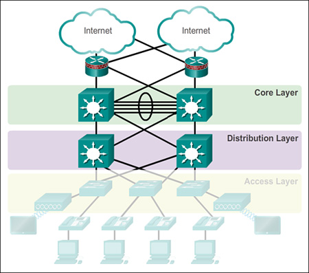
The following is a review of a basic implementation of the OSPFv3 routing protocol for IPv6. Figure 5-5 displays the topology used for configuring OSPFv3.
The routers in the topology have a starting configuration, including enabled interface IPv6 addresses. There is currently no static routing or dynamic routing configured on any of the routers. All interfaces on Routers R1, R2, and R3 (except the loopback on R2) are within the OSPF backbone area. Example 5-9 shows the OSPFv3 configuration for R1.
Example 5-9 Basic Single-Area OSPFv3 Configuration for R1
R1(config)# ipv6 router ospf 10
R1(config-rtr)# router-id 1.1.1.1
R1(config-rtr)# auto-cost reference-bandwidth 1000
R1(config-rtr)# interface GigabitEthernet0/0
R1(config-if)# bandwidth 1000000
R1(config-if)# ipv6 ospf 10 area 0
R1(config-if)# interface Serial0/0/0
R1(config-if)# ipv6 ospf 10 area 0
R1(config-if)# interface Serial0/0/1
R1(config-if)# ipv6 ospf 10 area 0
From OSPFv3 router configuration mode on R1, the router ID is manually assigned and the reference bandwidth is adjusted to account for fast interfaces. Next the interfaces participating in OSPFv3 are configured. The Gigabit Ethernet 0/0 is also configured to reflect its true bandwidth. Notice how there is no wildcard mask required when configuring OSPFv3.
![]() show ipv6 ospf neighbor: This command verifies that the router has formed an adjacency with its neighboring routers. If the router ID of the neighboring router is not displayed, or if it does not show as being in a state of FULL, the two routers have not formed an OSPF adjacency. Example 5-10 shows the output for R1.
show ipv6 ospf neighbor: This command verifies that the router has formed an adjacency with its neighboring routers. If the router ID of the neighboring router is not displayed, or if it does not show as being in a state of FULL, the two routers have not formed an OSPF adjacency. Example 5-10 shows the output for R1.
Example 5-10 show ipv6 ospf neighbor Command
R1# show ipv6 ospf neighbor
OSPFv3 Router with ID (1.1.1.1) (Process ID 10)
Neighbor ID Pri State Dead Time Interface ID Interface
3.3.3.3 0 FULL/ - 00:00:39 6 Serial0/0/1
2.2.2.2 0 FULL/ - 00:00:36 6 Serial0/0/0
![]() show ipv6 protocols: This command provides a quick way to verify vital OSPFv3 configuration information, including the OSPF process ID, the router ID, and the interfaces enabled for OSPFv3. Example 5-11 shows the output for R1.
show ipv6 protocols: This command provides a quick way to verify vital OSPFv3 configuration information, including the OSPF process ID, the router ID, and the interfaces enabled for OSPFv3. Example 5-11 shows the output for R1.
Example 5-11 show ipv6 protocols Command
R1# show ipv6 protocols
IPv6 Routing Protocol is "connected"
IPv6 Routing Protocol is "ND"
IPv6 Routing Protocol is "ospf 10"
Router ID 1.1.1.1
Number of areas: 1 normal, 0 stub, 0 nssa
Interfaces (Area 0):
Serial0/0/1
Serial0/0/0
GigabitEthernet0/0
Redistribution:
None
![]() show ipv6 route ospf: This command provides specifics about OSPFv3 routes in the routing table. Example 5-12 shows the output for R1.
show ipv6 route ospf: This command provides specifics about OSPFv3 routes in the routing table. Example 5-12 shows the output for R1.
Example 5-12 show ipv6 route ospf Command
R1# show ipv6 route ospf
IPv6 Routing Table - default - 10 entries
Codes: C - Connected, L - Local, S - Static, U - Per-user Static route
B - BGP, R - RIP, H - NHRP, I1 - ISIS L1
I2 - ISIS L2, IA - ISIS interarea, IS - ISIS summary, D - EIGRP
EX - EIGRP external, ND - ND Default, NDp - ND Prefix, DCE - Destination
NDr - Redirect, O - OSPF Intra, OI - OSPF Inter, OE1 - OSPF ext 1
OE2 - OSPF ext 2, ON1 - OSPF NSSA ext 1, ON2 - OSPF NSSA ext 2
O 2001:DB8:CAFE:2::/64 [110/657]
via FE80::2, Serial0/0/0
O 2001:DB8:CAFE:3::/64 [110/1304]
via FE80::2, Serial0/0/0
O 2001:DB8:CAFE:A002::/64 [110/1294]
via FE80::2, Serial0/0/0
![]() show ipv6 ospf interface brief: This command is useful to display a summary and status of OSPFv3-enabled interfaces. Example 5-13 shows the output for R1.
show ipv6 ospf interface brief: This command is useful to display a summary and status of OSPFv3-enabled interfaces. Example 5-13 shows the output for R1.
Example 5-13 show ipv6 ospf interface Command
R1# show ipv6 ospf interface serial 0/0/0
Serial0/0/0 is up, line protocol is up
Link Local Address FE80::1, Interface ID 7
Area 0, Process ID 10, Instance ID 0, Router ID 1.1.1.1
Network Type POINT_TO_POINT, Cost: 647
Transmit Delay is 1 sec, State POINT_TO_POINT
Timer intervals configured, Hello 10, Dead 40, Wait 40, Retransmit 5
Hello due in 00:00:01
Graceful restart helper support enabled
Index 1/3/3, flood queue length 0
Next 0x0(0)/0x0(0)/0x0(0)
Last flood scan length is 2, maximum is 4
Last flood scan time is 0 msec, maximum is 0 msec
Neighbor Count is 1, Adjacent neighbor count is 1
Adjacent with neighbor 2.2.2.2
Suppress hello for 0 neighbor(s)
![]() Lab 5.1.1.9: Configuring Basic Single-Area OSPFv2
Lab 5.1.1.9: Configuring Basic Single-Area OSPFv2
In this lab, you will complete the following objectives:
![]() Part 1: Build the Network and Configure Basic Device Settings
Part 1: Build the Network and Configure Basic Device Settings
![]() Part 2: Configure and Verify OSPF Routing
Part 2: Configure and Verify OSPF Routing
![]() Part 3: Change Router ID Assignments
Part 3: Change Router ID Assignments
![]() Part 4: Configure OSPF Passive Interfaces
Part 4: Configure OSPF Passive Interfaces
![]() Part 5: Change OSPF Metrics
Part 5: Change OSPF Metrics
OSPF in Multiaccess Networks (5.1.2)
In a multiaccess environment, OSPF incorporates a mechanism to reduce the amount of OSPF message overhead. This topic discusses OSPF network types and the details of the DR/BDR election process.
OSPF Network Types (5.1.2.1)
To configure OSPF adjustments, start with a basic implementation of the OSPF routing protocol.
OSPF defines the following five network types:
![]() Point-to-point: Two routers interconnected over a common link. No other routers are on the link. This is often the configuration in WAN links, as shown in Figure 5-6.
Point-to-point: Two routers interconnected over a common link. No other routers are on the link. This is often the configuration in WAN links, as shown in Figure 5-6.

![]() Broadcast multiaccess: Multiple routers interconnected over an Ethernet network, as shown in Figure 5-7.
Broadcast multiaccess: Multiple routers interconnected over an Ethernet network, as shown in Figure 5-7.

![]() Nonbroadcast multiaccess (NBMA): Multiple routers interconnected in a network that does not allow broadcasts, such as Frame Relay, as shown in Figure 5-8.
Nonbroadcast multiaccess (NBMA): Multiple routers interconnected in a network that does not allow broadcasts, such as Frame Relay, as shown in Figure 5-8.

![]() Point-to-multipoint: Multiple routers interconnected in a hub-and-spoke topology over an NBMA network. Often used to connect branch sites (spokes) to a central site (hub), as shown in Figure 5-9.
Point-to-multipoint: Multiple routers interconnected in a hub-and-spoke topology over an NBMA network. Often used to connect branch sites (spokes) to a central site (hub), as shown in Figure 5-9.

![]() Virtual links: Special OSPF network used to interconnect distant OSPF areas to the backbone area, as shown in Figure 5-10.
Virtual links: Special OSPF network used to interconnect distant OSPF areas to the backbone area, as shown in Figure 5-10.

A multiaccess network is a network with multiple devices on the same shared media, which are sharing communications. Ethernet LANs are the most common example of broadcast multiaccess networks. In broadcast networks, all devices on the network see all broadcast and multicast frames. They are multiaccess networks because there can be numerous hosts, printers, routers, and other devices that are all members of the same network.
Challenges in Multiaccess Networks (5.1.2.2)
Multiaccess networks can create two challenges for OSPF regarding the flooding of LSAs:
![]() Creation of multiple adjacencies: Ethernet networks could potentially interconnect many OSPF routers over a common link. Creating adjacencies with every router is unnecessary and undesirable. This would lead to an excessive number of LSAs exchanged between routers on the same network.
Creation of multiple adjacencies: Ethernet networks could potentially interconnect many OSPF routers over a common link. Creating adjacencies with every router is unnecessary and undesirable. This would lead to an excessive number of LSAs exchanged between routers on the same network.
![]() Extensive flooding of LSAs: Link-state routers flood their link-state packets when OSPF is initialized, or when there is a change in the topology. This flooding can become excessive.
Extensive flooding of LSAs: Link-state routers flood their link-state packets when OSPF is initialized, or when there is a change in the topology. This flooding can become excessive.
The following formula can be used to calculate the number of required adjacencies. The number of adjacencies required for any number of routers (designated as n) on a multiaccess network is:
n (n – 1) / 2
Figure 5-11 shows a simple topology of four routers, all of which are attached to the same multiaccess Ethernet network.

Without some type of mechanism to reduce the number of adjacencies, collectively these routers would form six adjacencies: 4 (4 – 1) / 2 = 6. Table 5-1 shows that as routers are added to the network, the number of adjacencies increases dramatically.

OSPF Designated Router (5.1.2.3)
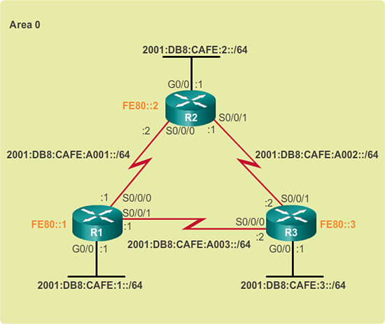
The solution to managing the number of adjacencies and the flooding of LSAs on a multiaccess network is the designated router (DR). On multiaccess networks, OSPF elects a DR to be the collection and distribution point for LSAs sent and received. A backup designated router (BDR) is also elected in case the DR fails. The BDR listens passively to this exchange and maintains a relationship with all the routers. If the DR stops producing Hello packets, the BDR promotes itself and assumes the role of DR.
All other non-DR or non-BDR routers become a DROTHER (a router that is neither the DR nor the BDR). DROTHERs only form full adjacencies with the DR and BDR in the network. Instead of flooding LSAs to all routers in the network, DROTHERs only send their LSAs to the DR and BDR using the multicast address 224.0.0.6 (all DR routers).
In Figure 5-12, R1 sends LSAs to the DR. The BDR also listens.

The DR is responsible for forwarding the LSAs from R1 to all other routers. The DR uses the multicast address 224.0.0.5 (all OSPF routers). The end result is that there is only one router doing all the flooding of all LSAs in the multiaccess network, as shown in Figure 5-13.
DR/BDR elections only occur in multiaccess networks and do not occur in point-to-point networks.
Verifying DR/BDR Roles (5.1.2.4)
In the multiaccess topology shown in Figure 5-14, there are three routers interconnected over a common Ethernet multiaccess network, 192.168.1.0/28. Each router is configured with the indicated IP address on the Gigabit Ethernet 0/0 interface.

Because the routers are connected over a common multiaccess broadcast network, OSPF has automatically elected a DR and BDR. In this example, R3 has been elected as the DR because its router ID is 3.3.3.3, which is the highest in this network. R2 is the BDR because it has the second-highest router ID in the network.
To verify the roles of the router, use the show ip ospf interface command, as shown in Figure 5-15.
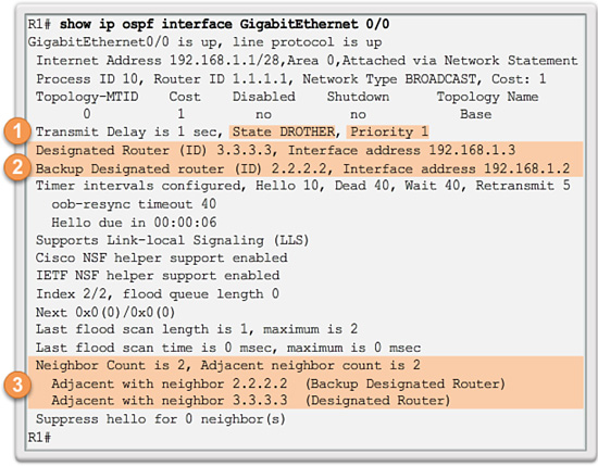
The output generated by R1 confirms that
![]() R1 is not the DR or BDR, but is a DROTHER with a default priority of 1. (1)
R1 is not the DR or BDR, but is a DROTHER with a default priority of 1. (1)
![]() The DR is R3 with router ID 3.3.3.3 at IP address 192.168.1.3, while the BDR is R2 with router ID 2.2.2.2 at IP address 192.168.1.2. (2)
The DR is R3 with router ID 3.3.3.3 at IP address 192.168.1.3, while the BDR is R2 with router ID 2.2.2.2 at IP address 192.168.1.2. (2)
![]() R1 has two adjacencies: one with the BDR and one with the DR. (3)
R1 has two adjacencies: one with the BDR and one with the DR. (3)
Figure 5-16 shows the output for R2.

The output for R2 confirms that
![]() R2 is the BDR with a default priority of 1. (1)
R2 is the BDR with a default priority of 1. (1)
![]() The DR is R3 with router ID 3.3.3.3 at IP address 192.168.1.3, while the BDR is R2 with router ID 2.2.2.2 at IP address 192.168.1.2. (2)
The DR is R3 with router ID 3.3.3.3 at IP address 192.168.1.3, while the BDR is R2 with router ID 2.2.2.2 at IP address 192.168.1.2. (2)
![]() R2 has two adjacencies: one with a neighbor with router ID 1.1.1.1 (R1) and the other with the DR. (3)
R2 has two adjacencies: one with a neighbor with router ID 1.1.1.1 (R1) and the other with the DR. (3)
Figure 5-17 shows the output for R3.

The output for R3 confirms that
![]() R3 is the DR with a default priority of 1. (1)
R3 is the DR with a default priority of 1. (1)
![]() The DR is R3 with router ID 3.3.3.3 at IP address 192.168.1.3, while the BDR is R2 with router ID 2.2.2.2 at IP address 192.168.1.2. (2)
The DR is R3 with router ID 3.3.3.3 at IP address 192.168.1.3, while the BDR is R2 with router ID 2.2.2.2 at IP address 192.168.1.2. (2)
![]() R3 has two adjacencies: one with a neighbor with router ID 1.1.1.1 (R1) and the other with the BDR. (3)
R3 has two adjacencies: one with a neighbor with router ID 1.1.1.1 (R1) and the other with the BDR. (3)
Verifying DR/BDR Adjacencies (5.1.2.5)
To verify the OSPF adjacencies, use the show ip ospf neighbor command, as shown in Figure 5-18.

Unlike serial links that only display a state of FULL/-, the state of neighbors in multi-access networks can be
![]() FULL/DROTHER: This is a DR or BDR router that is fully adjacent with a non-DR or BDR router. These two neighbors can exchange Hello packets, updates, queries, replies, and acknowledgments.
FULL/DROTHER: This is a DR or BDR router that is fully adjacent with a non-DR or BDR router. These two neighbors can exchange Hello packets, updates, queries, replies, and acknowledgments.
![]() FULL/DR: The router is fully adjacent with the indicated DR neighbor. These two neighbors can exchange Hello packets, updates, queries, replies, and acknowledgments.
FULL/DR: The router is fully adjacent with the indicated DR neighbor. These two neighbors can exchange Hello packets, updates, queries, replies, and acknowledgments.
![]() FULL/BDR: The router is fully adjacent with the indicated BDR neighbor. These two neighbors can exchange Hello packets, updates, queries, replies, and acknowledgments.
FULL/BDR: The router is fully adjacent with the indicated BDR neighbor. These two neighbors can exchange Hello packets, updates, queries, replies, and acknowledgments.
![]() 2-WAY/DROTHER: The non-DR or BDR router has a neighbor relationship with another non-DR or BDR router. These two neighbors exchange Hello packets.
2-WAY/DROTHER: The non-DR or BDR router has a neighbor relationship with another non-DR or BDR router. These two neighbors exchange Hello packets.
The normal state for an OSPF router is usually FULL. If a router is stuck in another state, it is an indication that there are problems in forming adjacencies. The only exception to this is the 2-WAY state, which is normal in a multiaccess broadcast network.
In multiaccess networks, DROTHERs only form FULL adjacencies with the DR and BDR. However, DROTHERs will still form a 2-WAY neighbor adjacency with any DROTHERs that join the network. This means that all DROTHER routers in the multiaccess network still receive Hello packets from all other DROTHER routers. In this way, they are aware of all routers in the network. When two DROTHER routers form a neighbor adjacency, the neighbor state displays as 2-WAY/DROTHER.
The output generated by R1 confirms that R1 has adjacencies with router
![]() R2 with router ID 2.2.2.2 is in a FULL state, and the role of R2 is BDR. (1)
R2 with router ID 2.2.2.2 is in a FULL state, and the role of R2 is BDR. (1)
![]() R3 with router ID 3.3.3.3 is in a FULL state, and the role of R3 is DR. (2)
R3 with router ID 3.3.3.3 is in a FULL state, and the role of R3 is DR. (2)
Figure 5-19 shows the output for R2.

The output for R2 confirms that R2 has adjacencies with router
![]() R1 with router ID 1.1.1.1 is in a FULL state, and R1 is neither the DR nor BDR. (1)
R1 with router ID 1.1.1.1 is in a FULL state, and R1 is neither the DR nor BDR. (1)
![]() R3 with router ID 3.3.3.3 is in a FULL state, and the role of R3 is DR. (2)
R3 with router ID 3.3.3.3 is in a FULL state, and the role of R3 is DR. (2)
Figure 5-20 shows the output for R3.

The output for R3 confirms that R3 has adjacencies with router
![]() R1 with router ID 1.1.1.1 is in a FULL state, and R1 is neither the DR nor BDR. (1)
R1 with router ID 1.1.1.1 is in a FULL state, and R1 is neither the DR nor BDR. (1)
![]() R2 with router ID 2.2.2.2 is in a FULL state, and the role of R2 is BDR. (2)
R2 with router ID 2.2.2.2 is in a FULL state, and the role of R2 is BDR. (2)
Default DR/BDR Election Process (5.1.2.6)
How do the DR and BDR get elected? The OSPF DR and BDR election decision is based on the following criteria, in sequential order:
1. The routers in the network elect the router with the highest interface priority as the DR. The router with the second-highest interface priority is elected as the BDR. The priority can be configured to be any number between 0 and 255. The higher the priority, the more likely the router will be selected as the DR. If the priority is set to 0, the router is not capable of becoming the DR. The default priority of multiaccess broadcast interfaces is 1. Therefore, unless otherwise configured, all routers have an equal priority value and must rely on another tie-breaking method during the DR/BDR election.
2. If the interface priorities are equal, the router with the highest router ID is elected the DR. The router with the second-highest router ID is the BDR.
Recall that the router ID is determined in one of three ways:
![]() The router ID can be manually configured.
The router ID can be manually configured.
![]() If no router IDs are configured, the router ID is determined by the highest loopback IP address.
If no router IDs are configured, the router ID is determined by the highest loopback IP address.
![]() If no loopback interfaces are configured, the router ID is determined by the highest active IPv4 address.
If no loopback interfaces are configured, the router ID is determined by the highest active IPv4 address.
In an IPv6 network, if there are no IPv4 addresses configured on the router, the router ID must be manually configured with the router-id rid command; otherwise, OSPFv3 does not start.
All Ethernet router interfaces have a default priority of 1. As a result, based on the selection criteria previously listed, the OSPF router ID is used to elect the DR and BDR. R3, with the highest router ID, becomes the DR, and R2, with the second-highest router ID, becomes the BDR.
The DR and BDR election process takes place as soon as the first router with an OSPF-enabled interface is active on the multiaccess network. This can happen when the routers are powered on, or when the OSPF network command for that interface is configured. The election process only takes a few seconds. If all of the routers on the multiaccess network have not finished booting, it is possible that a router with a lower router ID becomes the DR. (This can be a lower-end router that takes less time to boot.)
DR/BDR Election Process (5.1.2.7)
OSPF DR and BDR elections are not preemptive. If a new router with a higher priority or higher router ID is added to the network after the DR and BDR election, the newly added router does not take over the DR or the BDR role. This is because those roles have already been assigned. The addition of a new router does not initiate a new election process.
After the DR is elected, it remains the DR until one of the following events occurs:
![]() The DR fails
The DR fails
![]() The OSPF process on the DR fails or is stopped
The OSPF process on the DR fails or is stopped
![]() The multiaccess interface on the DR fails or is shut down
The multiaccess interface on the DR fails or is shut down
If the DR fails, the BDR is automatically promoted to DR. This is the case even if another DROTHER with a higher priority or router ID is added to the network after the initial DR/BDR election. However, after a BDR is promoted to DR, a new BDR election occurs and the DROTHER with the higher priority or router ID is elected as the new BDR.
Figures 5-21 to 5-24 illustrate various scenarios relating to the DR and BDR election process.


In Figure 5-21, the current DR (R3) fails; therefore, the preelected BDR (R2) assumes the role of DR. Subsequently, an election is held to choose a new BDR. Because R1 is the only DROTHER, it is elected as the BDR.
In Figure 5-22, R3 has rejoined the network after several minutes of being unavailable. Because the DR and BDR already exist, R3 does not take over either role; instead, it becomes a DROTHER.
In Figure 5-23, a new router (R4) with a higher router ID is added to the network. DR (R2) and BDR (R1) retain the DR and BDR roles. R4 automatically becomes a DROTHER.
In Figure 5-24, R2 has failed. The BDR (R1) automatically becomes the DR, and an election process selects R4 as the BDR because it has the higher router ID.
The OSPF Priority (5.1.2.8)
The DR becomes the focal point for the collection and distribution of LSAs; therefore, this router must have sufficient CPU and memory capacity to handle the workload. It is possible to influence the DR/BDR election process through configurations.
If the interface priorities are equal on all routers, the router with the highest router ID is elected the DR. It is possible to configure the router ID to manipulate the DR/BDR election. However, this process only works if there is a stringent plan for setting the router ID on all routers. In large networks, this can be cumbersome.
Instead of relying on the router ID, it is better to control the election by setting interface priorities. Priorities are an interface-specific value, which means that it provides better control on a multiaccess network. This also allows a router to be the DR in one network and a DROTHER in another.
To set the priority of an interface, use the following commands:
![]() ip ospf priority value: OSPFv2 interface command
ip ospf priority value: OSPFv2 interface command
![]() ipv6 ospf priority value: OSPFv3 interface command
ipv6 ospf priority value: OSPFv3 interface command
The value can be
![]() 0: Does not become a DR or BDR.
0: Does not become a DR or BDR.
![]() 1 – 255: The higher the priority value, the more likely the router becomes the DR or BDR on the interface.
1 – 255: The higher the priority value, the more likely the router becomes the DR or BDR on the interface.
In the multiaccess broadcast topology shown in Figure 5-14, all routers have an equal OSPF priority because the priority value defaults to 1 for all router interfaces. Therefore, the router ID is used to determine the DR (R3) and BDR (R2). Changing the priority value on an interface from 1 to a higher value would enable the router to become a DR or BDR router during the next election.
If the interface priority is configured after OSPF is enabled, the administrator must shut down the OSPF process on all routers, and then reenable the OSPF process, to force a new DR/BDR election.
Changing the OSPF Priority (5.1.2.9)
Recall in Figure 5-14 that R3 is the DR and R2 is the BDR. It has been decided that
![]() R1 should be the DR and will be configured with a priority of 255.
R1 should be the DR and will be configured with a priority of 255.
![]() R2 should be the BDR and will be left with the default priority of 1.
R2 should be the BDR and will be left with the default priority of 1.
![]() R3 should never be a DR or BDR and will be configured with a priority of 0.
R3 should never be a DR or BDR and will be configured with a priority of 0.
Example 5-14 shows the commands to change the R1 interface Gigabit 0/0 priority from 1 to 255 and to change the R3 interface Gigabit 0/0 priority from 1 to 0.
Example 5-14 Changing the Interface Priority
R1(config)# interface GigabitEthernet 0/0
R1(config-if)# ip ospf priority 255
R1(config-if)# end
R1#![]()
R3(config)# interface GigabitEthernet 0/0
R3(config-if)# ip ospf priority 0
R3(config-if)# end
R3#
The changes do not automatically take effect because the DR and BDR are already elected. Therefore, the OSPF election must be negotiated using one of the following methods:
![]() Shut down the router interfaces and then reenable them starting with the DR, then the BDR, and then all other routers.
Shut down the router interfaces and then reenable them starting with the DR, then the BDR, and then all other routers.
![]() Reset the OSPF process using the clear ip ospf process privileged EXEC mode command on all routers.
Reset the OSPF process using the clear ip ospf process privileged EXEC mode command on all routers.
Example 5-15 displays how to clear the OSPF process on R1.
Example 5-15 Clearing the OSPF Process on R1
R1# clear ip ospf process
Reset ALL OSPF processes? [no]: yes
R1#
*Apr 6 16:00:44.282: %OSPF-5-ADJCHG: Process 10, Nbr 2.2.2.2 on GigabitEthernet0/0
from FULL to DOWN, Neighbor Down: Interface down or detached
*Apr 6 16:00:44.282: %OSPF-5-ADJCHG: Process 10, Nbr 3.3.3.3 on GigabitEthernet0/0
from FULL to DOWN, Neighbor Down: Interface down or detached
R1#
Assume that the clear ip ospf process privileged EXEC mode command has also been configured on R2 and R3. Notice the OSPF state information generated.
The output displayed in Example 5-16 confirms that R1 is now the DR with a priority of 255 and identifies the new neighbor adjacencies of R1.
Example 5-16 Verifying Role and Adjacencies on R1
R1# show ip ospf interface GigabitEthernet 0/0
GigabitEthernet0/0 is up, line protocol is up
Internet Address 192.168.1.1/28, Area 0, Attached via Network Statement
Process ID 10, Router ID 1.1.1.1, Network Type BROADCAST, Cost: 1
Topology-MTID Cost Disabled Shutdown Topology Name
0 1 no no Base
Transmit Delay is 1 sec, State DR, Priority 255
Designated Router (ID) 1.1.1.1, Interface address 192.168.1.1
Backup Designated router (ID) 2.2.2.2, Interface address 192.168.1.2
Timer intervals configured, Hello 10, Dead 40, Wait 40, Retransmit 5
oob-resync timeout 40
Hello due in 00:00:05
Supports Link-local Signaling (LLS)
Cisco NSF helper support enabled
IETF NSF helper support enabled
Index 2/2, flood queue length 0
Next 0x0(0)/0x0(0)
Last flood scan length is 1, maximum is 2
Last flood scan time is 0 msec, maximum is 0 msec
Neighbor Count is 2, Adjacent neighbor count is 2
Adjacent with neighbor 2.2.2.2 (Backup Designated Router)
Adjacent with neighbor 3.3.3.3
Suppress hello for 0 neighbor(s)
R1# show ip ospf neighbor
Neighbor ID Pri State Dead Time Address Interface
2.2.2.2 1 FULL/BDR 00:00:30 192.168.1.2 GigabitEthernet0/0
3.3.3.3 0 FULL/DROTHER 00:00:38 192.168.1.3 GigabitEthernet0/0
R1#
![]() Activity 5.1.2.10: Identify OSPF Network Type Terminology
Activity 5.1.2.10: Identify OSPF Network Type Terminology
Go to the course online to perform this practice activity.
![]() Activity 5.1.2.11: Select the Designated Router
Activity 5.1.2.11: Select the Designated Router
Go to the course online to perform this practice activity.
 Packet Tracer Activity 5.1.2.12: Determining the DR and BDR
In this activity, you will examine DR and BDR roles and watch the roles change when there is a change in the network. You will then modify the priority to control the roles and force a new election. Finally, you will verify that routers are filling the desired roles.
![]() Lab 5.1.2.13: Configuring OSPFv2 on a Multiaccess Network
Lab 5.1.2.13: Configuring OSPFv2 on a Multiaccess Network
In this lab, you will complete the following objectives:
![]() Part 1: Build the Network and Configure Basic Device Settings
Part 1: Build the Network and Configure Basic Device Settings
![]() Part 2: Configure and Verify OSPFv2 on the DR, BDR, and DROTHER
Part 2: Configure and Verify OSPFv2 on the DR, BDR, and DROTHER
![]() Part 3: Configure OSPFv2 Interface Priority to Determine the DR and BDR
Part 3: Configure OSPFv2 Interface Priority to Determine the DR and BDR
Default Route Propagation (5.1.3)
Without some mechanism for advertising a default route to other OSPF routers in the organization, each router would need to be configured with a static default route. This topic discusses how to configure a router to send other OSPF routers a default route.
Propagating a Default Static Route in OSPFv2 (5.1.3.1)
With OSPF, the router connected to the Internet is used to propagate a default route to other routers in the OSPF routing domain. This router is sometimes called the edge, the entrance, or the gateway router. However, in OSPF terminology, the router located between an OSPF routing domain and a non-OSPF network is also called the autonomous system boundary router (ASBR).
In Figure 5-25, R2 is single-homed to a service provider. Therefore, all that is required for R2 to reach the Internet is a default static route to the service provider.

In this example, a loopback interface with IP address 209.165.200.225 is used to simulate the connection to the service provider.
To propagate a default route, the edge router (R2) must be configured with
![]() A default static route using the ip route 0.0.0.0 0.0.0.0 {ip-address | exit-intf} command.
A default static route using the ip route 0.0.0.0 0.0.0.0 {ip-address | exit-intf} command.
![]() The default-information originate router configuration mode command. This instructs R2 to be the source of the default route information and propagate the default static route in OSPF updates.
The default-information originate router configuration mode command. This instructs R2 to be the source of the default route information and propagate the default static route in OSPF updates.
Example 5-17 shows how to configure a fully specified default static route to the service provider and then propagate that route in the OSPF process.
Example 5-17 Configuring and Propagating a Default Route in OSPFv2
R2(config)# ip route 0.0.0.0 0.0.0.0 loopback 0 209.165.200.226
R2(config)# router ospf 10
R2(config-router)# default-information originate
R2(config-router)# end
R2#
Verifying the Propagated Default Route (5.1.3.2)
Verify the default route settings on R2 using the show ip route command, as shown in Example 5-18.
Example 5-18 Verifying the Default Route on R2
R2# show ip route | begin Gateway
Gateway of last resort is 209.165.200.226 to network 0.0.0.0
S* 0.0.0.0/0 [1/0] via 209.165.200.226, Loopback0
172.16.0.0/16 is variably subnetted, 5 subnets, 3 masks
O 172.16.1.0/24 [110/65] via 172.16.3.1, 00:01:44, Serial0/0/0
C 172.16.2.0/24 is directly connected, GigabitEthernet0/0
L 172.16.2.1/32 is directly connected, GigabitEthernet0/0
C 172.16.3.0/30 is directly connected, Serial0/0/0
L 172.16.3.2/32 is directly connected, Serial0/0/0
O 192.168.1.0/24 [110/65] via 192.168.10.10, 00:01:12, Serial0/0/1
192.168.10.0/24 is variably subnetted, 3 subnets, 2 masks
O 192.168.10.4/30 [110/128] via 192.168.10.10, 00:01:12, Serial0/0/1
[110/128] via 172.16.3.1, 00:01:12, Serial0/0/0
C 192.168.10.8/30 is directly connected, Serial0/0/1
L 192.168.10.9/32 is directly connected, Serial0/0/1
209.165.200.0/24 is variably subnetted, 2 subnets, 2 masks
C 209.165.200.224/30 is directly connected, Loopback0
L 209.165.200.225/32 is directly connected, Loopback0
The output in Example 5-19 verifies that the default route has been propagated to R1.
Example 5-19 Verifying That R1 Received the Default Route
R1# show ip route | begin Gateway
Gateway of last resort is 172.16.3.2 to network 0.0.0.0
O*E2 0.0.0.0/0 [110/1] via 172.16.3.2, 00:19:37, Serial0/0/0
172.16.0.0/16 is variably subnetted, 5 subnets, 3 masks
C 172.16.1.0/24 is directly connected, GigabitEthernet0/0
L 172.16.1.1/32 is directly connected, GigabitEthernet0/0
O 172.16.2.0/24 [110/65] via 172.16.3.2, 00:21:19, Serial0/0/0
C 172.16.3.0/30 is directly connected, Serial0/0/0
L 172.16.3.1/32 is directly connected, Serial0/0/0
O 192.168.1.0/24 [110/65] via 192.168.10.6, 00:20:49, Serial0/0/1
192.168.10.0/24 is variably subnetted, 3 subnets, 2 masks
C 192.168.10.4/30 is directly connected, Serial0/0/1
L 192.168.10.5/32 is directly connected, Serial0/0/1
O 192.168.10.8/30 [110/128] via 192.168.10.6, 00:20:49, Serial0/0/1
[110/128] via 172.16.3.2, 00:20:49, Serial0/0/0
R1#
Notice that the route source is O*E2, signifying that it was learned using OSPF. The asterisk identifies this as a good candidate for the default route. The E2 designation identifies that it is an external route.
External routes are either external type 1 or external type 2. The difference between the two is in the way the cost (metric) of the route is being calculated. The cost of a type 2 route is always the external cost, regardless of the interior cost to reach that route. A type 1 cost is the addition of the external cost and the internal cost used to reach that route. A type 1 route is always preferred over a type 2 route for the same destination.
Propagating a Default Static Route in OSPFv3 (5.1.3.3)
The process of propagating a default static route in OSPFv3 is almost identical to that in OSPFv2.
In Figure 5-26, R2 is single-homed to a service provider. Therefore, all that is required for R2 to reach the Internet is a default static route to the service provider.

In this example, a loopback interface with the IP address of 2001:DB8:FEED:1::1/64 is used to simulate the connection to the service provider.
To propagate a default route, the edge router (R2) must be configured with
![]() A default static route using the ipv6 route ::/0 {ipv6-address | exit-intf} command.
A default static route using the ipv6 route ::/0 {ipv6-address | exit-intf} command.
![]() The default-information originate router configuration mode command. This instructs R2 to be the source of the default route information and propagate the default static route in OSPF updates.
The default-information originate router configuration mode command. This instructs R2 to be the source of the default route information and propagate the default static route in OSPF updates.
Example 5-20 shows how to configure a fully specified default static route to the service provider and propagate that route in OSPF.
Example 5-20 Configuring and Propagating a Default Route in OSPFv3
R2(config)# ipv6 route 0::/0 loopback0 2001:DB8:FEED:1::2
R2(config)# ipv6 router ospf 10
R2(config-rtr)# default-information originate
R2(config-rtr)# end
R2#
Verifying the Propagated IPv6 Default Route (5.1.3.4)
Verify the default static route setting on R2 using the show ipv6 route command, as shown in Example 5-21.
Example 5-21 Verifying the Default Route on R2
R2# show ipv6 route static
IPv6 Routing Table - default - 12 entries
Codes: C - Connected, L - Local, S - Static, U - Per-user Static route
B - BGP, R - RIP, H - NHRP, I1 - ISIS L1
I2 - ISIS L2, IA - ISIS interarea, IS - ISIS summary, D - EIGRP
EX - EIGRP external, ND - ND Default, NDp - ND Prefix, DCE - Destination
NDr - Redirect, O - OSPF Intra, OI - OSPF Inter, OE1 - OSPF ext 1
OE2 - OSPF ext 2, ON1 - OSPF NSSA ext 1, ON2 - OSPF NSSA ext 2
S ::/0 [1/0]
via 2001:DB8:FEED:1::2, Loopback0
The output in Example 5-22 verifies that the default route has been propagated to R1.
Example 5-22 Verifying That R1 Received the Default Route
R1# show ipv6 route ospf | begin OE2 ::/0
OE2 ::/0 [110/1], tag 10
via FE80::2, Serial0/0/0
O 2001:DB8:CAFE:2::/64 [110/648]
via FE80::2, Serial0/0/0
O 2001:DB8:CAFE:3::/64 [110/648]
via FE80::2, Serial0/0/0
O 2001:DB8:CAFE:A002::/64 [110/1294]
via FE80::2, Serial0/0/0
Notice that the route source is OE2, signifying that it was learned using OSPFv3. The E2 designation identifies that it is an external route. Unlike the IPv4 routing table, IPv6 does not use the asterisk to signify that the route is a good candidate for the default route.
Packet Tracer Activity 5.1.3.5: Propagating a Default Route in OSPFv2
In this activity, you will configure an IPv4 default route to the Internet and propagate that default route to other OSPF routers. You will then verify that the default route is in downstream routing tables and that hosts can now access a web server on the Internet.
Fine-Tuning OSPF Interfaces (5.1.4)
In some situations, the default behavior of OSPF might not be acceptable. This topic discusses how to modify the timer values on OSPF interfaces to fine-tune the operation of OSPF.
OSPF Hello and Dead Intervals (5.1.4.1)
The OSPF Hello and Dead intervals are configurable on a per-interface basis. The OSPF intervals must match or a neighbor adjacency does not occur.
To verify the currently configured interface intervals, use the show ip ospf interface command, as shown in Example 5-23. The Serial 0/0/0 Hello and Dead intervals are set to the default 10 seconds and 40 seconds, respectively.
Example 5-23 Verifying the OSPF Intervals on R1
R1# show ip ospf interface serial 0/0/0
Serial0/0/0 is up, line protocol is up
Internet Address 172.16.3.1/30, Area 0, Attached via Network Statement
Process ID 10, Router ID 1.1.1.1, Network Type POINT_TO_POINT, Cost: 64
Topology-MTID Cost Disabled Shutdown Topology Name
0 64 no no Base
Transmit Delay is 1 sec, State POINT_TO_POINT
Timer intervals configured, Hello 10, Dead 40, Wait 40, Retransmit 5
oob-resync timeout 40
Hello due in 00:00:03
Supports Link-local Signaling (LLS)
Cisco NSF helper support enabled
IETF NSF helper support enabled
Index 2/2, flood queue length 0
Next 0x0(0)/0x0(0)
Last flood scan length is 1, maximum is 1
Last flood scan time is 0 msec, maximum is 0 msec
Neighbor Count is 1, Adjacent neighbor count is 1
Adjacent with neighbor 2.2.2.2
Suppress hello for 0 neighbor(s)
R1#
Example 5-24 provides an example of using a filtering technique to display the OSPF intervals for the OSPF-enabled interface Serial 0/0/0 on R1.
Example 5-24 Filtering for OSPF Timer Intervals on R1
R1# show ip ospf interface | include Timer
Timer intervals configured, Hello 10, Dead 40, Wait 40, Retransmit 5
Timer intervals configured, Hello 10, Dead 40, Wait 40, Retransmit 5
Timer intervals configured, Hello 10, Dead 40, Wait 40, Retransmit 5
R1#
In Example 5-25, the show ip ospf neighbor command is used on R1 to verify that R1 is adjacent to R2 and R3.
Example 5-25 Verifying OSPF Dead Timer Values on R1
R1# show ip ospf neighbor
Neighbor ID Pri State Dead Time Address Interface
3.3.3.3 0 FULL/ - 00:00:35 192.168.10.6 Serial0/0/1
2.2.2.2 0 FULL/ - 00:00:33 172.16.3.2 Serial0/0/0
R1#
Notice in the output that the Dead Time is counting down from 40 seconds. By default, this value is refreshed every 10 seconds when R1 receives a Hello from the neighbor.
Modifying OSPFv2 Intervals (5.1.4.2)
It might be desirable to change the OSPF timers so that routers detect network failures in less time. Doing this increases traffic, but sometimes the need for quick convergence is more important than the extra traffic it creates.
The default Hello and Dead intervals are based on best practices and should only be altered in rare situations.
OSPF Hello and Dead intervals can be modified manually using the following interface configuration mode commands:
![]() ip ospf hello-interval seconds
ip ospf hello-interval seconds
![]() ip ospf dead-interval seconds
ip ospf dead-interval seconds
Use the no ip ospf hello-interval and no ip ospf dead-interval commands to reset the intervals to their default.
In Example 5-26, the Hello interval is modified to 5 seconds.
Example 5-26 Modifying the OSPFv2 Timer Intervals on R1
R1(config)# interface Serial 0/0/0
R1(config-if)# ip ospf hello-interval 5
R1(config-if)# ip ospf dead-interval 20
R1(config-if)# end
*Apr 7 17:28:21.529: %OSPF-5-ADJCHG: Process 10, Nbr 2.2.2.2 on Serial0/0/0 from
FULL to DOWN, Neighbor Down: Dead timer expired
R1#
Immediately after changing the Hello interval, the Cisco IOS automatically modifies the Dead interval to four times the Hello interval. However, it is always good practice to explicitly modify the timer instead of relying on an automatic IOS feature so that modifications are documented in the configuration. Therefore, the Dead interval is also manually set to 20 seconds on the R1 Serial 0/0/0 interface.
As displayed by the highlighted OSPFv2 adjacency message in Example 5-26, when the Dead Timer on R1 expires, R1 and R2 lose adjacency. This is because the values have only been altered on one side of the serial link between R1 and R2. Recall that the OSPF Hello and Dead intervals must match between neighbors.
Use the show ip ospf neighbor command on R1 to verify the neighbor adjacencies, as shown in Example 5-27.
Example 5-27 Verifying Lost Neighbor Adjacency with R2
R1# show ip ospf neighbor
Neighbor ID Pri State Dead Time Address Interface
3.3.3.3 0 FULL/ - 00:00:37 192.168.10.6 Serial0/0/1
R1#
Notice that the only neighbor listed is the 3.3.3.3 (R3) router and that R1 is no longer adjacent with the 2.2.2.2 (R2) neighbor. The timers set on Serial 0/0/0 do not affect the neighbor adjacency with R3.
To restore adjacency between R1 and R2, the R2 Serial 0/0/0 interface Hello interval is set to 5 seconds, as shown in Example 5-28.
Example 5-28 Modifying the OSPFv2 Hello Interval on R2
R2(config)# interface serial 0/0/0
R2(config-if)# ip ospf hello-interval 5
*Apr 7 17:41:49.001: %OSPF-5-ADJCHG: Process 10, Nbr 1.1.1.1 on Serial0/0/0 from
LOADING to FULL, Loading Done
R2(config-if)# end
R2#
Almost immediately, the IOS displays a message that adjacency has been established with a state of FULL. Verify the interface intervals using the show ip ospf interface command, as shown in Example 5-29.
Example 5-29 Verifying Reestablished Neighbor Adjacency with R1
R2# show ip ospf interface s0/0/0 | include Timer
Timer intervals configured, Hello 5, Dead 20, Wait 20, Retransmit 5
R2#
R2# show ip ospf neighbor
Neighbor ID Pri State Dead Time Address Interface
3.3.3.3 0 FULL/ - 00:00:35 192.168.10.10 Serial0/0/1
1.1.1.1 0 FULL/ - 00:00:17 172.16.3.1 Serial0/0/0
R2#
Notice that the Hello time is 5 seconds and that the Dead Time was automatically set to 20 seconds instead of the default 40 seconds. Remember that the OSPF automatically sets the Dead interval to four times the Hello interval.
OSPFv3 Hello and Dead intervals can be modified manually using the following interface configuration mode commands:
![]() ipv6 ospf hello-interval seconds
ipv6 ospf hello-interval seconds
![]() ipv6 ospf dead-interval seconds
ipv6 ospf dead-interval seconds
Use the no ipv6 ospf hello-interval and no ipv6 ospf dead-interval commands to reset the intervals to their default.
Refer to the IPv6 topology shown previously in Figure 5-26. Assume that the network has converged using OSPFv3. Example 5-30 shows the commands to modify the OSPFv3 Hello interval to 5 seconds.
Example 5-30 Modifying the OSPFv3 Timer Intervals on R1
R1(config)# interface Serial 0/0/0
R1(config-if)# ipv6 ospf hello-interval 5
R1(config-if)# ipv6 ospf dead-interval 20
R1(config-if)# end
R1#
*Apr 10 15:03:51.175: %OSPFv3-5-ADJCHG: Process 10, Nbr 2.2.2.2 on Serial0/0/0 from
FULL to DOWN, Neighbor Down: Dead timer expired
R1#
Immediately after changing the Hello interval, the Cisco IOS automatically modifies the Dead interval to four times the Hello interval. However, as with OSPFv2, it is always good practice to explicitly modify the timer instead of relying on an automatic IOS feature so that modifications are documented in the configuration. Therefore, the Dead interval is also manually set to 20 seconds on the R1 Serial 0/0/0 interface.
After the Dead timer on R1 expires, R1 and R2 lose adjacency, as displayed by the highlighted OSPFv3 adjacency message in Example 5-30, because the values have only been altered on one side of the serial link between R1 and R2. Recall that the OSPFv3 Hello and Dead intervals must be equivalent between neighbors.
Use the show ipv6 ospf neighbor command on R1 to verify the neighbor adjacencies, as shown in Example 5-31.
Example 5-31 Verifying Lost Neighbor Adjacency with R2
R1# show ipv6 ospf neighbor
R1#
Notice that R1 is no longer adjacent with the 2.2.2.2 (R2) neighbor. To restore adjacency between R1 and R2, the R2 Serial 0/0/0 interface Hello interval is set to 5 seconds, as shown in Example 5-32.
Example 5-32 Modifying the OSPFv3 Hello Interval on R3
R2(config)# interface serial 0/0/0
R2(config-if)# ipv6 ospf hello-interval 5
R2(config-if)#
*Apr 10 15:07:28.815: %OSPFv3-5-ADJCHG: Process 10, Nbr 1.1.1.1 on Serial0/0/0 from LOADING to FULL, Loading Done
R2(config-if)# end
R2#
Almost immediately, the IOS displays a message that adjacency has been established with a state of FULL. Verify the interface intervals using the show ipv6 ospf interface command, as shown in Example 5-33.
Example 5-33 Verifying Reestablished Neighbor Adjacency with R1
R2# show ipv6 ospf interface s0/0/0 | include Timer
Timer intervals configured, Hello 5, Dead 20, Wait 20, Retransmit 5
R2#
R2# show ipv6 ospf neighbor
OSPFv3 Router with ID (2.2.2.2) (Process ID 10)
Neighbor ID Pri State Dead Time Interface ID Interface
3.3.3.3 0 FULL/ - 00:00:38 7 Serial0/0/1
1.1.1.1 0 FULL/ - 00:00:19 6 Serial0/0/0
R2#
Notice that the Hello timer is 5 seconds and that the Dead timer was automatically set to 20 seconds instead of the default 40 seconds. Remember that the OSPF automatically sets the Dead interval to four times the Hello interval.
Secure OSPF (5.1.5)
As long as OSPF is configured correctly between two neighbors, the OSPF messages will be received and used to update the link-state database. This means that anyone knowing or guessing the correct configurations can manipulate the routing behavior of an unsuspecting OSPF router. This topic discusses the importance of authenticating routing updates and how to enable authentication in OSPFv2.
Routers Are Targets (5.1.5.1)
The role of routers in a network is so crucial that they are often the targets of network attacks. Network administrators must be aware that routers are at risk from attack just as much as end-user systems.
In general, routing systems can be attacked by disrupting the routing peers or by falsifying the information carried within the routing protocol. Falsified routing information can generally be used to cause systems to misinform (lie to) each other, cause a denial of service (DoS) attack, or cause traffic to follow a path it would not normally follow. The consequences of falsifying routing information are
![]() Redirecting traffic to create routing loops (shown in Figure 5-27)
Redirecting traffic to create routing loops (shown in Figure 5-27)

![]() Redirecting traffic so that it can be monitored on an insecure link
Redirecting traffic so that it can be monitored on an insecure link
![]() Redirecting traffic to discard it
Redirecting traffic to discard it
For example, in Figure 5-27, an attacker has been able to connect directly to the link between Routers R1 and R2. The attacker injects false routing information destined to Router R1 only, indicating that R2 is the preferred destination to the 192.168.10.10/32 host route. Although R1 has a routing table entry to the directly connected 192.168.10.0/24 network, it adds the injected route to its routing table because of the longer subnet mask. A route with a longer matching subnet mask is considered to be superior to a route with a shorter subnet mask. Consequently, when a router receives a packet, it selects the longer subnet mask, because it is a more precise route to the destination.
When PC3 sends a packet to PC1 (192.168.10.10/24), R1 does not forward the packet to the PC1 host. Instead, it routes the packet to Router R2, because the apparent best path to 192.168.10.10/32 is through R2. When R2 gets the packet, it looks in its routing table and forwards the packet back to R1, which creates the loop.
To mitigate against routing protocol attacks, configure OSPF authentication.
Secure Routing Updates (5.1.5.2)
When neighbor authentication has been configured on a router, the router authenticates the source of each routing update packet that it receives. This is accomplished by the exchange of an authenticating key (sometimes referred to as a password) that is known to both the sending and the receiving router.
To exchange routing update information in a secure manner, enable OSPF authentication. OSPF authentication can either be none (or null), simple, or Message Digest 5 (MD5).
OSPF supports three types of authentication:
![]() Null: This is the default method and means that no authentication is used for OSPF.
Null: This is the default method and means that no authentication is used for OSPF.
![]() Simple password authentication: This is also referred to as plaintext authentication because the password in the update is sent in plaintext over the network. This is considered to be a legacy method of OSPF authentication.
Simple password authentication: This is also referred to as plaintext authentication because the password in the update is sent in plaintext over the network. This is considered to be a legacy method of OSPF authentication.
![]() MD5 authentication: This is the most secure and recommended method of authentication. MD5 authentication provides higher security because the password is never exchanged between peers. Instead it is calculated using the MD5 algorithm. Matching results authenticate the sender.
MD5 authentication: This is the most secure and recommended method of authentication. MD5 authentication provides higher security because the password is never exchanged between peers. Instead it is calculated using the MD5 algorithm. Matching results authenticate the sender.
Figure 5-28 shows an example of MD5 authentication between two neighbors.
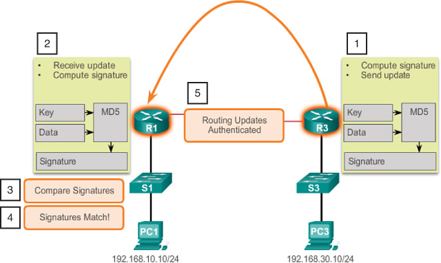
In the figure, R3 uses the MD5 algorithm to generate a signature (sometimes called a “hash”) and includes it in the authentication field inside the message header for routing update (1). R1 receives the message and does the same MD5 calculation (2). R1 then compares the generated signature with the one received from R3 (3). If the signatures match (4), the routing update is authenticated (5) and will be used by R1 to make routing decisions. If the signatures do not match, R1 discards the message.
MD5 Authentication (5.1.5.3)
Figure 5-29 shows another example of how MD5 authentication is used to authenticate two neighboring OSPF routers.

In the figure, R1 combines the routing message with the preshared secret key and calculates the signature using the MD5 algorithm. The signature is also known as a hash value. R1 adds the signature to the routing message and sends it to R2. MD5 does not encrypt the message; therefore, the content is easily readable. R2 opens the packet, combines the routing message with the preshared secret key, and calculates the signature using the MD5 algorithm.
![]() If the signatures match, R2 accepts the routing update.
If the signatures match, R2 accepts the routing update.
![]() If the signatures do not match, R2 discards the update.
If the signatures do not match, R2 discards the update.
OSPFv3 (OSPF for IPv6) does not include any authentication capabilities of its own. Instead it relies entirely on IPsec to secure communications between neighbors using the ipv6 ospf authentication ipsec spi interface configuration mode command. This is beneficial in simplifying the OSPFv3 protocol and standardizing its authentication mechanism.
Configuring OSPF MD5 Authentication (5.1.5.4)
OSPF supports routing protocol authentication using MD5. MD5 authentication can be enabled globally for all interfaces or on a per-interface basis.
To enable OSPF MD5 authentication globally, configure
![]() The ip ospf message-digest-key key md5 password interface configuration mode command
The ip ospf message-digest-key key md5 password interface configuration mode command
![]() The area area-id authentication message-digest router configuration mode command
The area area-id authentication message-digest router configuration mode command
This method forces authentication on all OSPF-enabled interfaces. If an interface is not configured with the ip ospf message-digest-key command, it will not be able to form adjacencies with other OSPF neighbors.
To provide more flexibility, authentication is now supported on a per-interface basis. To enable MD5 authentication on a per-interface basis, configure
![]() The ip ospf message-digest-key key md5 password interface configuration mode command
The ip ospf message-digest-key key md5 password interface configuration mode command
![]() The ip ospf authentication message-digest interface configuration mode command
The ip ospf authentication message-digest interface configuration mode command
Global and per-interface OSPF MD5 authentication can be used on the same router. However, the interface setting overrides the global setting. MD5 authentication passwords do not have to be the same throughout an area; however, they do need to be the same between neighbors.
For example, assume that all routers in the previous Figure 5-25 have converged using OSPF and that routing is functioning properly. OSPF authentication will be implemented on all routers.
OSPF MD5 Authentication Example (5.1.5.5)
Example 5-34 shows the configurations for R1 to enable OSPF MD5 authentication on all interfaces.
Example 5-34 Enabling MD5 Authentication Globally on R1
R1(config)# router ospf 10
R1(config-router)# area 0 authentication message-digest
R1(config-router)# exit
*Apr 8 09:58:09.899: %OSPF-5-ADJCHG: Process 10, Nbr 2.2.2.2 on Serial0/0/0 from
FULL to DOWN, Neighbor Down: Dead timer expired
*Apr 8 09:58:28.627: %OSPF-5-ADJCHG: Process 10, Nbr 3.3.3.3 on Serial0/0/1 from
FULL to DOWN, Neighbor Down: Dead timer expired
R1(config)# interface GigabitEthernet 0/0
R1(config-if)# ip ospf message-digest-key 1 md5 CISCO-123
R1(config-if)# exit
R1(config)# interface Serial 0/0/0
R1(config-if)# ip ospf message-digest-key 1 md5 CISCO-123
R1(config-if)# exit
R1(config)# interface Serial 0/0/1
R1(config-if)# ip ospf message-digest-key 1 md5 CISCO-123
R1(config-if)#
Notice the informational messages stating that the OSPF neighbor adjacencies with R2 and R3 have changed to the Down state, because R2 and R3 have not yet been configured to support MD5 authentication.
As an alternative to globally enabling MD5 authentication, Example 5-35 demonstrates how to configure R1 to enable OSPF MD5 authentication on a per-interface basis.
Example 5-35 Enabling OSPF MD5 Authentication on the R1 Interfaces
R1(config)# interface GigabitEthernet 0/0
R1(config-if)# ip ospf message-digest-key 1 md5 CISCO-123
R1(config-if)# ip ospf authentication message-digest
R1(config-if)# exit
R1(config)# interface Serial 0/0/0
R1(config-if)# ip ospf message-digest-key 1 md5 CISCO-123
R1(config-if)# ip ospf authentication message-digest
R1(config-if)# exit
R1(config)# interface Serial 0/0/1
R1(config-if)# ip ospf message-digest-key 1 md5 CISCO-123
R1(config-if)# ip ospf authentication message-digest
R1(config-if)# exit
R1(config)#
*Apr 8 10:20:10.647: %OSPF-5-ADJCHG: Process 10, Nbr 2.2.2.2 on Serial0/0/0 from
FULL to DOWN, Neighbor Down: Dead timer expired
*Apr 8 10:20:50.007: %OSPF-5-ADJCHG: Process 10, Nbr 3.3.3.3 on Serial0/0/1 from
FULL to DOWN, Neighbor Down: Dead timer expired
R1(config)#
Again, notice how the OSPF neighbor adjacencies have changed to the Down state.
Verifying OSPF MD5 Authentication (5.1.5.6)
Assume that R2 and R3 are correctly configured for authentication. To verify that OSPF MD5 authentication is enabled, use the show ip ospf interface privileged EXEC mode command. By verifying that the routing table is complete, successful authentication can be confirmed.
Example 5-36 verifies the OSPF MD5 authentication on the Serial 0/0/0 interface on R1.
Example 5-36 Verifying the OSPF MD5 Authentication Settings on R1
R1# show ip ospf interface Serial 0/0/0
Serial0/0/0 is up, line protocol is up
Internet Address 172.16.3.1/30, Area 0, Attached via Network Statement
Process ID 10, Router ID 1.1.1.1, Network Type POINT_TO_POINT, Cost: 64
Topology-MTID Cost Disabled Shutdown Topology Name
0 64 no no Base
Transmit Delay is 1 sec, State POINT_TO_POINT
Timer intervals configured, Hello 5, Dead 20, Wait 20, Retransmit 5
oob-resync timeout 40
Hello due in 00:00:02
Supports Link-local Signaling (LLS)
Cisco NSF helper support enabled
IETF NSF helper support enabled
Index 2/2, flood queue length 0
Next 0x0(0)/0x0(0)
Last flood scan length is 1, maximum is 1
Last flood scan time is 0 msec, maximum is 0 msec
Neighbor Count is 1, Adjacent neighbor count is 1
Adjacent with neighbor 2.2.2.2
Suppress hello for 0 neighbor(s)
Message digest authentication enabled
Youngest key id is 1
R1# show ip ospf interface | include Message
Message digest authentication enabled
Message digest authentication enabled
Message digest authentication enabled
R1#
Example 5-37 confirms that the authentication is successful. R1 has received routes from both R2 and R3.
Example 5-37 Verifying the Routing Table on R1
R1# show ip route ospf | begin Gateway
Gateway of last resort is 172.16.3.2 to network 0.0.0.0
O*E2 0.0.0.0/0 [110/1] via 172.16.3.2, 00:33:17, Serial0/0/0
172.16.0.0/16 is variably subnetted, 5 subnets, 3 masks
O 172.16.2.0/24 [110/65] via 172.16.3.2, 00:33:17, Serial0/0/0
O 192.168.1.0/24 [110/65] via 192.168.10.6, 00:30:43, Serial0/0/1
192.168.10.0/24 is variably subnetted, 3 subnets, 2 masks
O 192.168.10.8/30 [110/128] via 192.168.10.6, 00:30:43, Serial0/0/1
[110/128] via 172.16.3.2, 00:33:17, Serial0/0/0
R1#
Packet Tracer Activity 5.1.5.7: Configuring OSPFv2 Advanced Features
In this activity, OSPF is already configured and all end devices currently have full connectivity. You will modify the default OSPF routing configuration by changing the Hello and Dead timers, adjusting the bandwidth of a link, and enabling OSPF authentication. Then you will verify that full connectivity is restored for all end devices.
![]() Lab 5.1.5.8: Configuring OSPFv2 Advanced Features
Lab 5.1.5.8: Configuring OSPFv2 Advanced Features
In this lab, you will complete the following objectives:
![]() Part 1: Build the Network and Configure Basic Device Settings
Part 1: Build the Network and Configure Basic Device Settings
![]() Part 2: Configure and Verify OSPF Routing
Part 2: Configure and Verify OSPF Routing
![]() Part 3: Change OSPF Metrics
Part 3: Change OSPF Metrics
![]() Part 4: Configure and Propagate a Static Default Route
Part 4: Configure and Propagate a Static Default Route
![]() Part 5: Configure OSPF Authentication
Part 5: Configure OSPF Authentication
Troubleshooting Single-Area OSPF Implementations (5.2)
Troubleshooting is a key skill for a network administrator. This section reviews the unique aspects of troubleshooting single-area OSPFv2 and OSPFv3.
Components of Troubleshooting Single-Area OSPF (5.2.1)
This topic reviews the OSPF states and common OSPF verification commands. Using these commands in a systematic troubleshooting method is then discussed.
Overview (5.2.1.1)
OSPF is a popularly implemented routing protocol used in large enterprise networks. Troubleshooting problems related to the exchange of routing information is one of the most essential skills for a network professional who is involved in the implementation and maintenance of large, routed enterprise networks that use OSPF as the IGP.
Issues with forming OSPF adjacencies include
![]() The interfaces are not on the same network.
The interfaces are not on the same network.
![]() OSPF network types do not match.
OSPF network types do not match.
![]() OSPF Hello or Dead timers do not match.
OSPF Hello or Dead timers do not match.
![]() The interface to neighbor is incorrectly configured as passive.
The interface to neighbor is incorrectly configured as passive.
![]() There is a missing or incorrect OSPF network command.
There is a missing or incorrect OSPF network command.
![]() Authentication is misconfigured.
Authentication is misconfigured.
OSPF States (5.2.1.2)
To troubleshoot OSPF, it is important to understand how OSPF routers traverse different OSPF states when adjacencies are being established. Figure 5-30 shows the OSPF states from DOWN to FULL.

The following reviews some specific details about the OSPF states:
Down State
![]() No Hello packets received = Down.
No Hello packets received = Down.
![]() Router sends Hello packets.
Router sends Hello packets.
![]() Transition to Init state.
Transition to Init state.
Init State
![]() Hello packets are received from the neighbor.
Hello packets are received from the neighbor.
![]() They contain the sending router’s router ID.
They contain the sending router’s router ID.
![]() Transition to Two-Way state.
Transition to Two-Way state.
Two-Way State
![]() On Ethernet links, elect a DR and a BDR.
On Ethernet links, elect a DR and a BDR.
![]() Transition to ExStart state.
Transition to ExStart state.
![]() Negotiate master/slave relationship and DBD packet sequence number.
Negotiate master/slave relationship and DBD packet sequence number.
![]() The master initiates the DBD packet exchange.
The master initiates the DBD packet exchange.
Exchange State
![]() Routers exchange DBD packets.
Routers exchange DBD packets.
![]() If additional router information is required, transition to Loading; otherwise, transition to Full.
If additional router information is required, transition to Loading; otherwise, transition to Full.
Loading State
![]() LSRs and LSUs are used to gain additional route information.
LSRs and LSUs are used to gain additional route information.
![]() Routes are processed using the SPF algorithm.
Routes are processed using the SPF algorithm.
![]() Transition to the Full state.
Transition to the Full state.
Full State
![]() Routers have converged.
Routers have converged.
When troubleshooting OSPF neighbors, be aware that the FULL or 2WAY state is normal. All other states are transitory; that is, the router should not remain in those states for extended periods of time.
OSPF Troubleshooting Commands (5.2.1.3)
There are many different OSPF commands that can be used to help in the troubleshooting process. The following summarizes the most common of these commands:
![]() show ip protocols (Example 5-38): Used to verify vital OSPF configuration information, including the OSPF process ID, the router ID, networks the router is advertising, the neighbors the router is receiving updates from, and the default administrative distance, which is 110 for OSPF.
show ip protocols (Example 5-38): Used to verify vital OSPF configuration information, including the OSPF process ID, the router ID, networks the router is advertising, the neighbors the router is receiving updates from, and the default administrative distance, which is 110 for OSPF.
Example 5-38 Verify the OSPF Settings on R1
R1# show ip protocols
*** IP Routing is NSF aware ***
Routing Protocol is "ospf 10"
Outgoing update filter list for all interfaces is not set
Incoming update filter list for all interfaces is not set
Router ID 1.1.1.1
Number of areas in this router is 1. 1 normal 0 stub 0 nssa
Maximum path: 4
Routing for Networks:
172.16.1.1 0.0.0.0 area 0
172.16.3.1 0.0.0.0 area 0
192.168.10.5 0.0.0.0 area 0
Passive Interface(s):
GigabitEthernet0/0
Routing Information Sources:
Gateway Distance Last Update
3.3.3.3 110 00:08:35
2.2.2.2 110 00:08:35
Distance: (default is 110)
R1#
![]() show ip ospf neighbor (Example 5-39): Used to verify that the router has formed an adjacency with its neighboring routers. Displays the neighbor router ID, neighbor priority, OSPF state, Dead timer, neighbor interface IP address, and interface that the neighbor is accessible through. If the router ID of the neighboring router is not displayed, or if it does not show as a state of FULL or 2WAY, the two routers have not formed an OSPF adjacency. If two routers do not establish adjacency, link-state information will not be exchanged. Incomplete link-state databases can cause inaccurate SPF trees and routing tables. Routes to destination networks might not exist or might not be the most optimum path.
show ip ospf neighbor (Example 5-39): Used to verify that the router has formed an adjacency with its neighboring routers. Displays the neighbor router ID, neighbor priority, OSPF state, Dead timer, neighbor interface IP address, and interface that the neighbor is accessible through. If the router ID of the neighboring router is not displayed, or if it does not show as a state of FULL or 2WAY, the two routers have not formed an OSPF adjacency. If two routers do not establish adjacency, link-state information will not be exchanged. Incomplete link-state databases can cause inaccurate SPF trees and routing tables. Routes to destination networks might not exist or might not be the most optimum path.
Example 5-39 Verify the OSPF Neighbor Adjacencies on R1
R1# show ip ospf neighbor
Neighbor ID Pri State Dead Time Address Interface
2.2.2.2 1 FULL/BDR 00:00:30 192.168.1.2 GigabitEthernet0/0
3.3.3.3 0 FULL/DROTHER 00:00:38 192.168.1.3 GigabitEthernet0/0
R1#
![]() show ip ospf interface (Example 5-40): Used to display the OSPF parameters configured on an interface, such as the OSPF process ID that the interface is assigned to, the area that the interfaces are in, the cost of the interface, and the Hello and Dead intervals. Adding the interface name and number to the command displays output for a specific interface.
show ip ospf interface (Example 5-40): Used to display the OSPF parameters configured on an interface, such as the OSPF process ID that the interface is assigned to, the area that the interfaces are in, the cost of the interface, and the Hello and Dead intervals. Adding the interface name and number to the command displays output for a specific interface.
Example 5-40 Verify the OSPF Interface Settings of S0/0/0 on R1
R1# show ip ospf interface Serial 0/0/0
Serial0/0/0 is up, line protocol is up
Internet Address 172.16.3.1/30, Area 0, Attached via Network Statement
Process ID 10, Router ID 1.1.1.1, Network Type POINT_TO_POINT, Cost: 64
Topology-MTID Cost Disabled Shutdown Topology Name
0 64 no no Base
Transmit Delay is 1 sec, State POINT_TO_POINT
Timer intervals configured, Hello 5, Dead 20, Wait 20, Retransmit 5
oob-resync timeout 40
Hello due in 00:00:02
Supports Link-local Signaling (LLS)
Cisco NSF helper support enabled
IETF NSF helper support enabled
Index 2/2, flood queue length 0
Next 0x0(0)/0x0(0)
Last flood scan length is 1, maximum is 1
Last flood scan time is 0 msec, maximum is 0 msec
Neighbor Count is 1, Adjacent neighbor count is 1
Adjacent with neighbor 2.2.2.2
Suppress hello for 0 neighbor(s)
Message digest authentication enabled
Youngest key id is 1
R1#
![]() show ip ospf (Example 5-41): Used to examine the OSPF process ID and router ID. Additionally, this command displays the OSPF area information, as well as the last time the SPF algorithm was calculated.
show ip ospf (Example 5-41): Used to examine the OSPF process ID and router ID. Additionally, this command displays the OSPF area information, as well as the last time the SPF algorithm was calculated.
Example 5-41 Displaying the OSPF Parameters on R1
R1# show ip ospf
Routing Process "ospf 10" with ID 1.1.1.1
Start time: 00:02:19.116, Time elapsed: 00:01:00.796
Supports only single TOS(TOS0) routes
Supports opaque LSA
Supports Link-local Signaling (LLS)
Supports area transit capability
Supports NSSA (compatible with RFC 3101)
Event-log enabled, Maximum number of events: 1000, Mode: cyclic
Router is not originating router-LSAs with maximum metric
Initial SPF schedule delay 5000 msecs
Minimum hold time between two consecutive SPFs 10000 msecs
Maximum wait time between two consecutive SPFs 10000 msecs
Incremental-SPF disabled
Minimum LSA interval 5 secs
Minimum LSA arrival 1000 msecs
LSA group pacing timer 240 secs
Interface flood pacing timer 33 msecs
Retransmission pacing timer 66 msecs
Number of external LSA 1. Checksum Sum 0x00A1FF
Number of opaque AS LSA 0. Checksum Sum 0x000000
Number of DCbitless external and opaque AS LSA 0
Number of DoNotAge external and opaque AS LSA 0
Number of areas in this router is 1. 1 normal 0 stub 0 nssa
Number of areas transit capable is 0
External flood list length 0
IETF NSF helper support enabled
Cisco NSF helper support enabled
Reference bandwidth unit is 100 mbps
Area BACKBONE(0)
Number of interfaces in this area is 3
Area has no authentication
SPF algorithm last executed 00:00:36.936 ago
SPF algorithm executed 3 times
Area ranges are
Number of LSA 3. Checksum Sum 0x016D60
Number of opaque link LSA 0. Checksum Sum 0x000000
Number of DCbitless LSA 0
Number of indication LSA 0
Number of DoNotAge LSA 0
Flood list length 0
R1#
![]() show ip route ospf (Example 5-42): Used to display only the OSPF-learned routes in the routing table. The output shows that R1 has learned about four remote networks through OSPF.
show ip route ospf (Example 5-42): Used to display only the OSPF-learned routes in the routing table. The output shows that R1 has learned about four remote networks through OSPF.
Example 5-42 Verify the OSPF Routes in the Routing Table on R1
R1# show ip route ospf | begin Gateway
Gateway of last resort is 172.16.3.2 to network 0.0.0.0
O*E2 0.0.0.0/0 [110/1] via 172.16.3.2, 00:33:17, Serial0/0/0
172.16.0.0/16 is variably subnetted, 5 subnets, 3 masks
O 172.16.2.0/24 [110/65] via 172.16.3.2, 00:33:17, Serial0/0/0
O 192.168.1.0/24 [110/65] via 192.168.10.6, 00:30:43, Serial0/0/1
192.168.10.0/24 is variably subnetted, 3 subnets, 2 masks
O 192.168.10.8/30 [110/128] via 192.168.10.6, 00:30:43, Serial0/0/1
[110/128] via 172.16.3.2, 00:33:17, Serial0/0/0
R1#
![]() clear ip ospf [ process-id ] process: Used to reset the OSPFv2 neighbor adjacencies.
clear ip ospf [ process-id ] process: Used to reset the OSPFv2 neighbor adjacencies.
Components of Troubleshooting OSPF (5.2.1.4)
As shown in Figure 5-31, OSPF problems usually relate to
![]() Neighbor adjacencies
Neighbor adjacencies
![]() Missing routes
Missing routes
![]() Path selection
Path selection

When troubleshooting neighbor issues, verify whether the router has established adjacencies with neighboring routers using the show ip ospf neighbors command. If there is no adjacency, the routers cannot exchange routes. Verify whether interfaces are operational and enabled for OSPF using the show ip interface brief and the show ip ospf interface commands. If the interfaces are operational and enabled for OSPF, ensure that interfaces on both routers are configured for the same OSPF area and the interfaces are not configured as passive interfaces.
If adjacency between two routers is established, verify that there are OSPF routes in the routing table using the show ip route ospf command. If there are no OSPF routes, verify that there are no other routing protocols with lower administrative distances running in the network. Verify whether all the required networks are advertised into OSPF. Also verify whether an access list is configured on a router that would filter either incoming or outgoing routing updates.
If all the required routes are in the routing table, but the path that traffic takes is not correct, verify the OSPF cost on interfaces on the path. Also be careful in cases where the interfaces are faster than 100 Mb/s, because all interfaces above this bandwidth have the same OSPF cost by default.
![]() Activity 5.2.1.5: Identify the Troubleshooting Command
Activity 5.2.1.5: Identify the Troubleshooting Command
Go to the course online to perform this practice activity.
Troubleshoot Single-Area OSPFv2 Routing Issues (5.2.2)
This topic discusses a specific example of troubleshooting a single-area OSPFv2 issue.
Troubleshooting Neighbor Issues (5.2.2.1)
This example will highlight how to troubleshoot neighbor problems. In the previous OSPFv2 topology, shown in Figure 5-25, all the routers have been configured to support OSPF routing. A quick look at the R1 routing table, as shown in Example 5-43, reveals that it is not adding any OSPF routes.
Example 5-43 OSPF Routes Not Installed in R1 Routing Table
R1# show ip route | begin Gateway
Gateway of last resort is not set
172.16.0.0/16 is variably subnetted, 4 subnets, 3 masks
C 172.16.1.0/24 is directly connected, GigabitEthernet0/0
L 172.16.1.1/32 is directly connected, GigabitEthernet0/0
C 172.16.3.0/30 is directly connected, Serial0/0/0
L 172.16.3.1/32 is directly connected, Serial0/0/0
R1#
There are multiple reasons why this could be. However, a prerequisite for the neighbor relationship to form between two routers is OSI Layer 3 connectivity. The output in Example 5-44 confirms that the S0/0/0 interface is up and active. The successful ping also confirms that the R2 serial interface is active.
Example 5-44 Verify Layer 3 Connectivity to R2
R1# show ip interface brief
Interface IP-Address OK? Method Status Protocol
Embedded-Service-Engine0/0 unassigned YES unset administratively down down
GigabitEthernet0/0 172.16.1.1 YES manual up up
GigabitEthernet0/1 unassigned YES unset administratively down down
Serial0/0/0 172.16.3.1 YES manual up up
Serial0/0/1 unassigned YES TFTP up up
R1#
R1# ping 172.16.3.2
Type escape sequence to abort.
Sending 5, 100-byte ICMP Echos to 172.16.3.2, timeout is 2 seconds:
!!!!!
Success rate is 100 percent (5/5), round-trip min/avg/max = 12/14/16 ms
R1#
A successful ping does not mean that an adjacency will form because it is possible to have overlapping subnets. You still have to verify that interfaces on the connected devices share the same subnet. If the ping was not successful, check the cabling and verify that interfaces on connected devices are configured correctly and operational.
For an interface to be enabled for OSPF, a matching network command must be configured under the OSPF routing process. Active OSPF interfaces can be verified using the show ip ospf interface command. The output in Example 5-45 verifies that the Serial 0/0/0 interface is enabled for OSPF. If connected interfaces on two routers are not enabled for OSPF, the neighbors will not form an adjacency.
Example 5-45 Verify That OSPF Is Enabled on the R1 Interfaces
R1# show ip ospf interface serial 0/0/0
Serial0/0/0 is up, line protocol is up
Internet Address 172.16.3.1/30, Area 0, Attached via Network Statement
Process ID 10, Router ID 1.1.1.1, Network Type POINT_TO_POINT, Cost: 64
Topology-MTID Cost Disabled Shutdown Topology Name
0 64 no no Base
Transmit Delay is 1 sec, State POINT_TO_POINT
Timer intervals configured, Hello 5, Dead 20, Wait 20, Retransmit 5
oob-resync timeout 40
No Hellos (Passive interface)
Supports Link-local Signaling (LLS)
Cisco NSF helper support enabled
IETF NSF helper support enabled
Index 2/2, flood queue length 0
Next 0x0(0)/0x0(0)
Last flood scan length is 1, maximum is 1
Last flood scan time is 0 msec, maximum is 0 msec
Neighbor Count is 0, Adjacent neighbor count is 0
Suppress hello for 0 neighbor(s)
Message digest authentication enabled
Youngest key id is 1
R1#
Verify the OSPF settings using the show ip protocols command. The output in Example 5-46 verifies that OSPF is enabled and also lists the networks being advertised as enabled by the network command.
Example 5-46 Verify OSPF Settings on R1
R1# show ip protocols
*** IP Routing is NSF aware ***
Routing Protocol is "ospf 10"
Outgoing update filter list for all interfaces is not set
Incoming update filter list for all interfaces is not set
Router ID 1.1.1.1
Number of areas in this router is 1. 1 normal 0 stub 0 nssa
Maximum path: 4
Routing for Networks:
172.16.1.1 0.0.0.0 area 0
172.16.3.1 0.0.0.0 area 0
Passive Interface(s):
GigabitEthernet0/0
Serial0/0/0
Routing Information Sources:
Gateway Distance Last Update
3.3.3.3 110 00:50:03
2.2.2.2 110 04:27:25
Distance: (default is 110)
R1#
If an IP address on an interface falls within a network that has been enabled for OSPF, the interface will be enabled for OSPF. However, notice that the Serial 0/0/0 interface is listed as passive. Recall that the passive-interface command stops both outgoing and incoming routing updates because the effect of the command causes the router to stop sending and receiving Hello packets over an interface. For this reason, the routers will not become neighbors.
To disable the interface as passive, use the no passive-interface router configuration mode command, as shown in Example 5-47.
Example 5-47 Removing the passive-interface Command
R1(config)# router ospf 10
R1(config-router)# no passive-interface s0/0/0
R1(config-router)#
*Apr 9 13:14:15.454: %OSPF-5-ADJCHG: Process 10, Nbr 2.2.2.2 on Serial0/0/0 from
LOADING to FULL, Loading Done
R1(config-router)# end
R1#
After you disable the passive interface, the routers become adjacent, as indicated by the automatically generated information message. A quick verification of the routing table, as shown in Example 5-48, confirms that OSPF is now exchanging routing information.
Example 5-48 Verify That OSPF Routes Are Now in the R1 Routing Table
R1# show ip route ospf | begin Gateway
Gateway of last resort is 172.16.3.2 to network 0.0.0.0
O*E2 0.0.0.0/0 [110/1] via 172.16.3.2, 00:00:18, Serial0/0/0
172.16.0.0/16 is variably subnetted, 5 subnets, 3 masks
O 172.16.2.0/24 [110/65] via 172.16.3.2, 00:00:18, Serial0/0/0
O 192.168.1.0/24 [110/129] via 172.16.3.2, 00:00:18, Serial0/0/0
192.168.10.0/30 is subnetted, 1 subnets
O 192.168.10.8 [110/128] via 172.16.3.2, 00:00:18, Serial0/0/0
R1#
Another problem that can arise is when two neighboring routers have mismatched MTU sizes on their connecting interfaces. The MTU size is the largest network layer packet that the router will forward out each interface. Routers default to an MTU size of 1500 bytes. However, this value can be changed for IPv4 packets using the ip mtu size interface configuration command or the ipv6 mtu size interface command for IPv6 packets. If two connecting routers had mismatched MTU values, they would still attempt to form an adjacency but they would not exchange their LSDBs and the neighbor relationship would fail.
Troubleshooting OSPF Routing Table Issues (5.2.2.2)
Again, referring to the previous OSPFv2 topology in Figure 5-25 all the routers have been configured to support OSPF routing.
A quick look at the R1 routing table in Example 5-49 reveals that it receives default route information, the R2 LAN (172.16.2.0/24) and the link between R2 and R3 (192.168.10.8/30). However, it does not receive the R3 LAN OSPF route.
Example 5-49 Verify OSPF Routes in the R1 Routing Table
R1# show ip route | begin Gateway
Gateway of last resort is 172.16.3.2 to network 0.0.0.0
O*E2 0.0.0.0/0 [110/1] via 172.16.3.2, 00:05:26, Serial0/0/0
172.16.0.0/16 is variably subnetted, 5 subnets, 3 masks
C 172.16.1.0/24 is directly connected, GigabitEthernet0/0
L 172.16.1.1/32 is directly connected, GigabitEthernet0/0
O 172.16.2.0/24 [110/65] via 172.16.3.2, 00:05:26, Serial0/0/0
C 172.16.3.0/30 is directly connected, Serial0/0/0
L 172.16.3.1/32 is directly connected, Serial0/0/0
192.168.10.0/30 is subnetted, 1 subnets
O 192.168.10.8 [110/128] via 172.16.3.2, 00:05:26, Serial0/0/0
R1#
The output in Example 5-50 verifies the OSPF settings on R3. Notice that R3 only advertises the link between R3 and R2. It does not advertise the R3 LAN (192.168.1.0/24).
Example 5-50 Verify OSPF Settings on R3
R3# show ip protocols
*** IP Routing is NSF aware ***
Routing Protocol is "ospf 10"
Outgoing update filter list for all interfaces is not set
Incoming update filter list for all interfaces is not set
Router ID 3.3.3.3
Number of areas in this router is 1. 1 normal 0 stub 0 nssa
Maximum path: 4
Routing for Networks:
192.168.10.8 0.0.0.3 area 0
Passive Interface(s):
Embedded-Service-Engine0/0
GigabitEthernet0/0
GigabitEthernet0/1
GigabitEthernet0/3
RG-AR-IF-INPUT1
Routing Information Sources:
Gateway Distance Last Update
1.1.1.1 110 00:02:48
2.2.2.2 110 00:02:48
Distance: (default is 110)
R3#
For an interface to be enabled for OSPF, a matching network command must be configured under the OSPF routing process. The output in Example 5-51 confirms that the R3 LAN is not advertised in OSPF.
Example 5-51 Verify the OSPF Router Configuration on R3
R3# show running-config | section router ospf
router ospf 10
router-id 3.3.3.3
passive-interface default
no passive-interface Serial0/0/1
network 192.168.10.8 0.0.0.3 area 0
R3#
The configuration in Example 5-52 adds a network command for the R3 LAN. R3 should now advertise the R3 LAN to its OSPF neighbors.
Example 5-52 Add R3 LAN to Routing Configuration
R3# conf t
Enter configuration commands, one per line. End with CNTL/Z.
R3(config)# router ospf 10
R3(config-router)# network 192.168.1.0 0.0.0.255 area 0
R3(config-router)# end
R3#
The output in Example 5-53 verifies that the R3 LAN is now in the routing table of R1.
Example 5-53 Verify R1 Now Has Route to R3 LAN
R1# show ip route ospf | begin Gateway
Gateway of last resort is 172.16.3.2 to network 0.0.0.0
O*E2 0.0.0.0/0 [110/1] via 172.16.3.2, 00:08:38, Serial0/0/0
172.16.0.0/16 is variably subnetted, 5 subnets, 3 masks
O 172.16.2.0/24 [110/65] via 172.16.3.2, 00:08:38, Serial0/0/0
O 192.168.1.0/24 [110/129] via 172.16.3.2, 00:00:37, Serial0/0/0
192.168.10.0/30 is subnetted, 1 subnets
O 192.168.10.8 [110/128] via 172.16.3.2, 00:08:38, Serial0/0/0
R1#
Packet Tracer Activity 5.2.2.3: Troubleshooting Single-Area OSPFv2
In this activity, you will troubleshoot OSPF routing issues using ping and show commands to identify errors in the network configuration. Then, you will document the errors you discover and implement an appropriate solution. Finally, you will verify that end-to-end connectivity is restored.
Troubleshoot Single-Area OSPFv3 Routing Issues (5.2.3)
This topic discusses a specific example of troubleshooting a single-area OSPFv3 issue.
OSPFv3 Troubleshooting Commands (5.2.3.1)
Refer back to the OSPFv3 topology in Figure 5-26. Troubleshooting OSPFv3 is almost identical to OSPFv2; therefore, many OSPFv3 commands and troubleshooting criteria also apply to OSPFv3.
For example, the following are the equivalent commands used with OSPFv3:
![]() show ipv6 protocols (Example 5-54): This command is used to verify vital OSPFv3 configuration information, including the OSPFv3 process ID, the router ID, and the interfaces the router is receiving updates from.
show ipv6 protocols (Example 5-54): This command is used to verify vital OSPFv3 configuration information, including the OSPFv3 process ID, the router ID, and the interfaces the router is receiving updates from.
Example 5-54 Verify the OSPFv3 Settings on R1
R1# show ipv6 protocols
IPv6 Routing Protocol is "connected"
IPv6 Routing Protocol is "ND"
IPv6 Routing Protocol is "ospf 10"
Router ID 1.1.1.1
Number of areas: 1 normal, 0 stub, 0 nssa
Interfaces (Area 0):
Serial0/0/0
GigabitEthernet0/0
Redistribution:
None
R1#
![]() show ipv6 ospf neighbor (Example 5-55): Used to verify that the router has formed an adjacency with its neighboring routers. This output displays the neighbor router ID, the neighbor priority, OSPFv3 state, Dead timer, neighbor interface ID, and the interface that the neighbor is accessible through. If the router ID of the neighboring router is not displayed, or if it does not show as a state of FULL or 2WAY, the two routers have not formed an OSPFv3 adjacency. If two routers do not establish adjacency, link-state information will not be exchanged. Incomplete link-state databases can cause inaccurate SPF trees and routing tables. Routes to destination networks might not exist, or they might not be the most optimum paths.
show ipv6 ospf neighbor (Example 5-55): Used to verify that the router has formed an adjacency with its neighboring routers. This output displays the neighbor router ID, the neighbor priority, OSPFv3 state, Dead timer, neighbor interface ID, and the interface that the neighbor is accessible through. If the router ID of the neighboring router is not displayed, or if it does not show as a state of FULL or 2WAY, the two routers have not formed an OSPFv3 adjacency. If two routers do not establish adjacency, link-state information will not be exchanged. Incomplete link-state databases can cause inaccurate SPF trees and routing tables. Routes to destination networks might not exist, or they might not be the most optimum paths.
Example 5-55 Verify the OSPFv3 Neighbor Adjacencies on R1
R1# show ipv6 ospf neighbor
Neighbor ID Pri State Dead Time Interface ID Interface
2.2.2.2 1 FULL/- 00:00:33 7 Serial0/0/0
R1#
![]() show ipv6 ospf interface (Example 5-56): Used to display the OSPFv3 parameters configured on an interface, such as the OSPFv3 process ID that the interface is assigned to, the area that the interfaces are in and the cost of the interface, and the Hello and Dead intervals. Adding the interface name and number to the command displays output for a specific interface.
show ipv6 ospf interface (Example 5-56): Used to display the OSPFv3 parameters configured on an interface, such as the OSPFv3 process ID that the interface is assigned to, the area that the interfaces are in and the cost of the interface, and the Hello and Dead intervals. Adding the interface name and number to the command displays output for a specific interface.
Example 5-56 Verify the OSPFv3 Interface Settings of S0/0/0 on R1
R1# show ipv6 ospf interface s0/0/0
Serial0/0/0 is up, line protocol is up
Link Local Address FE80::1, Interface ID 6
Area 0, Process ID 10, Instance ID 0, Router ID 1.1.1.1
Network Type POINT_TO_POINT, Cost: 647
Transmit Delay is 1 sec, State POINT_TO_POINT
Timer intervals configured, Hello 10, Dead 40, Wait 40, Retransmit 5
Hello due in 00:00:08
Graceful restart helper support enabled
Index 1/2/2, flood queue length 0
Next 0x0(0)/0x0(0)/0x0(0)
Last flood scan length is 2, maximum is 6
Last flood scan time is 0 msec, maximum is 0 msec
Neighbor Count is 1, Adjacent neighbor count is 1
Adjacent with neighbor 2.2.2.2
Suppress hello for 0 neighbor(s)
R1#
![]() show ipv6 ospf (Example 5-57): Used to examine the OSPF process ID and router ID, as well as information about the LSA transmissions.
show ipv6 ospf (Example 5-57): Used to examine the OSPF process ID and router ID, as well as information about the LSA transmissions.
Example 5-57 Verify the OSPFv3 Interface Settings of S0/0/0 on R1
R1# show ipv6 ospf
Routing Process "ospfv3 10" with ID 1.1.1.1
Event-log enabled, Maximum number of events: 1000, Mode: cyclic
Router is not originating router-LSAs with maximum metric
Initial SPF schedule delay 5000 msecs
Minimum hold time between two consecutive SPFs 10000 msecs
Maximum wait time between two consecutive SPFs 10000 msecs
Minimum LSA interval 5 secs
Minimum LSA arrival 1000 msecs
LSA group pacing timer 240 secs
Interface flood pacing timer 33 msecs
Retransmission pacing timer 66 msecs
Number of external LSA 1. Checksum Sum 0x0017E9
Number of areas in this router is 1. 1 normal 0 stub 0 nssa
Graceful restart helper support enabled
Reference bandwidth unit is 1000 mbps
RFC1583 compatibility enabled
Area BACKBONE(0)
Number of interfaces in this area is 2
SPF algorithm executed 8 times
Number of LSA 13. Checksum Sum 0x063D5D
Number of DCbitless LSA 0
Number of indication LSA 0
Number of DoNotAge LSA 0
Flood list length 0
R1#
![]() show ipv6 route ospf (Example 5-58): Used to display only the OSPFv3-learned routes in the routing table. The output shows that R1 has learned about four remote networks through OSPFv3.
show ipv6 route ospf (Example 5-58): Used to display only the OSPFv3-learned routes in the routing table. The output shows that R1 has learned about four remote networks through OSPFv3.
Example 5-58 Verify the OSPFv3 Routes in the R1 Routing Table
R1# show ipv6 route ospf
IPv6 Routing Table - default - 9 entries
Codes: C - Connected, L - Local, S - Static, U - Per-user Static route
B - BGP, R - RIP, H - NHRP, I1 - ISIS L1
I2 - ISIS L2, IA - ISIS interarea, IS - ISIS summary, D - EIGRP
EX - EIGRP external, ND - ND Default, NDp - ND Prefix, DCE - Destination
NDr - Redirect, O - OSPF Intra, OI - OSPF Inter, OE1 - OSPF ext 1
OE2 - OSPF ext 2, ON1 - OSPF NSSA ext 1, ON2 - OSPF NSSA ext 2
OE2 ::/0 [110/1], tag 10
via FE80::2, Serial0/0/0
O 2001:DB8:CAFE:2::/64 [110/648]
via FE80::2, Serial0/0/0
O 2001:DB8:CAFE:3::/64 [110/648]
via FE80::2, Serial0/0/0
O 2001:DB8:CAFE:A002::/64 [110/1294]
via FE80::2, Serial0/0/0
R1#
![]() clear ipv6 ospf [ process-id ] process: Used to reset the OSPFv3 neighbor adjacencies.
clear ipv6 ospf [ process-id ] process: Used to reset the OSPFv3 neighbor adjacencies.
Troubleshooting OSPFv3 (5.2.3.2)
Assume that all the routers in Figure 5-25 have been configured to support OSPFv3 routing. A quick look at the R1 IPv6 routing table in Example 5-59 reveals that it receives the default route, the R2 LAN (2001:DB8:CAFE:2::/64) and the link between R2 and R3 (2001:DB8:CAFE:A002::/64). However, it does not receive the R3 LAN OSPFv3 route (2001:DB8:CAFE:3::/64).
Example 5-59 Verify OSPFv3 Routes in the Routing Table of R1
R1# show ipv6 route ospf
IPv6 Routing Table - default - 8 entries
Codes: C - Connected, L - Local, S - Static, U - Per-user Static route
B - BGP, R - RIP, H - NHRP, I1 - ISIS L1
I2 - ISIS L2, IA - ISIS interarea, IS - ISIS summary, D - EIGRP
EX - EIGRP external, ND - ND Default, NDp - ND Prefix, DCE - Destination
NDr - Redirect, O - OSPF Intra, OI - OSPF Inter, OE1 - OSPF ext 1
OE2 - OSPF ext 2, ON1 - OSPF NSSA ext 1, ON2 - OSPF NSSA ext 2
OE2 ::/0 [110/1], tag 10
via FE80::2, Serial0/0/0
O 2001:DB8:CAFE:2::/64 [110/648]
via FE80::2, Serial0/0/0
O 2001:DB8:CAFE:A002::/64 [110/1294]
via FE80::2, Serial0/0/0
R1#
The output in Example 5-60 verifies the OSPFv3 settings on R3. Notice that OSPF is only enabled on the Serial 0/0/1 interface. It appears that it is not enabled on the G0/0 R3 interface.
Example 5-60 Verify OSPFv3 Settings on R3
R3# show ipv6 protocols
IPv6 Routing Protocol is "connected"
IPv6 Routing Protocol is "ND"
IPv6 Routing Protocol is "ospf 10"
Router ID 3.3.3.3
Number of areas: 1 normal, 0 stub, 0 nssa
Interfaces (Area 0):
Serial0/0/1
Redistribution:
None
R3#
Unlike OSPFv2, OSPFv3 does not use the network command. Instead, OSPFv3 is enabled directly on the interface. The output in Example 5-61 confirms that the R3 interface is not enabled for OSPFv3.
Example 5-61 Verify the OSPFv3 Router Configuration on R3
R3# show running-config interface g0/0
Building configuration...
Current configuration : 196 bytes
!
interface GigabitEthernet0/0
description R3 LAN
no ip address
duplex auto
speed auto
ipv6 address FE80::3 link-local
ipv6 address 2001:DB8:CAFE:3::1/64
end
R3#
The configuration in Example 5-62 enables OSPFv3 on the R3 Gigabit Ethernet 0/0 interface. R3 should now advertise the R3 LAN to its OSPFv3 neighbors.
Example 5-62 Enable OSPFv3 on the R3 LAN
R3# conf t
Enter configuration commands, one per line. End with CNTL/Z.
R3(config)# interface g0/0
R3(config-if)# ipv6 ospf 10 area 0
R3(config-if)# end
R3#
The output in Example 5-63 verifies that the R3 LAN is now in the routing table of R1.
Example 5-63 Verify OSPFv3 Routes in the Routing Table of R1
R1# show ipv6 route ospf
IPv6 Routing Table - default - 9 entries
Codes: C - Connected, L - Local, S - Static, U - Per-user Static route
B - BGP, R - RIP, H - NHRP, I1 - ISIS L1
I2 - ISIS L2, IA - ISIS interarea, IS - ISIS summary, D - EIGRP
EX - EIGRP external, ND - ND Default, NDp - ND Prefix, DCE - Destination
NDr - Redirect, O - OSPF Intra, OI - OSPF Inter, OE1 - OSPF ext 1
OE2 - OSPF ext 2, ON1 - OSPF NSSA ext 1, ON2 - OSPF NSSA ext 2
OE2 ::/0 [110/1], tag 10
via FE80::2, Serial0/0/0
O 2001:DB8:CAFE:2::/64 [110/648]
via FE80::2, Serial0/0/0
O 2001:DB8:CAFE:3::/64 [110/1295]
via FE80::2, Serial0/0/0
O 2001:DB8:CAFE:A002::/64 [110/1294]
via FE80::2, Serial0/0/0
R1#
![]() Lab 5.2.3.3: Troubleshooting Basic Single-Area OSPFv2 and OSPFv3
Lab 5.2.3.3: Troubleshooting Basic Single-Area OSPFv2 and OSPFv3
In this lab, you will complete the following objectives:
![]() Part 1: Build the Network and Load Device Configurations
Part 1: Build the Network and Load Device Configurations
![]() Part 2: Troubleshoot Layer 3 Connectivity
Part 2: Troubleshoot Layer 3 Connectivity
![]() Part 3: Troubleshoot OSPFv2
Part 3: Troubleshoot OSPFv2
![]() Part 4: Troubleshoot OSPFv3
Part 4: Troubleshoot OSPFv3
![]() Lab 5.2.3.4: Troubleshooting Advanced Single-Area OSPFv2
Lab 5.2.3.4: Troubleshooting Advanced Single-Area OSPFv2
In this lab, you will complete the following objectives:
![]() Part 1: Build the Network and Load Device Configurations
Part 1: Build the Network and Load Device Configurations
![]() Part 2: Troubleshoot OSPF
Part 2: Troubleshoot OSPF
Summary (5.3)
![]() Class Activity 5.3.1.1: OSPF Troubleshooting Mastery
Class Activity 5.3.1.1: OSPF Troubleshooting Mastery
You have decided to change your routing protocol from RIPv2 to OSPFv2. Your small- to medium-sized business network topology will not change from its original physical settings. Use the diagram on the PDF for this activity as your company’s small- to medium-sized business network design.
Your addressing design is complete and you then configure your routers with IPv4 and VLSM. OSPF has been applied as the routing protocol. However, some routers are sharing routing information with each other and some are not.
Open the PDF file that accompanies this modeling activity and follow the directions to complete the activity.
When the steps in the directions are complete, regroup as a class and compare recorded activity correction times. The group taking the shortest time to find and fix the configuration error will be declared the winner only after successfully explaining how they found the error, fixed it, and proved that the topology is now working.
Packet Tracer Activity 5.3.1.2: Skills Integration Challenge
In this Skills Integration Challenge, your focus is on OSPFv2 advanced configurations. IP addressing has been configured for all devices. You will configure OSPFv2 routing with passive interfaces and default route propagation. You will modify the OSPFv2 configuration by adjusting timers and establishing MD5 authentication. Finally, you will verify your configurations and test connectivity between end devices.
OSPF defines five network types: point-to-point, broadcast multiaccess, nonbroadcast multiaccess, point-to-multipoint, and virtual links.
Multiaccess networks can create two challenges for OSPF regarding the flooding of LSAs: creation of multiple adjacencies and extensive flooding of LSAs. The solution to managing the number of adjacencies and the flooding of LSAs on a multiaccess network is the DR and BDR. If the DR stops producing Hellos, the BDR promotes itself and assumes the role of DR.
The routers in the network elect the router with the highest interface priority as DR. The router with the second-highest interface priority is elected the BDR. The higher the priority, the more likely the router will be selected as the DR. If set to 0, the router is not capable of becoming the DR. The default priority of multiaccess broadcast interfaces is 1. Therefore, unless otherwise configured, all routers have an equal priority value and must rely on another tie-breaking method during the DR/BDR election. If the interface priorities are equal, the router with the highest router ID is elected the DR. The router with the second-highest router ID is the BDR. The addition of a new router does not initiate a new election process.
To propagate a default route in OSPF, the router must be configured with a default static route, and the default-information originate command must be added to the configuration. Verify routes with the show ip route or show ipv6 route command.
To assist OSPF in making the correct path determination, the reference bandwidth must be changed to a higher value to accommodate networks with links faster than 100 Mb/s. To adjust the reference bandwidth, use the auto-cost reference-bandwidth Mbps router configuration mode command. To adjust the interface bandwidth, use the bandwidth kilobits interface configuration mode command. The cost can be manually configured on an interface using the ip ospf cost value interface configuration mode command.
The OSPF Hello and Dead intervals must match or a neighbor adjacency does not occur. To modify these intervals, use the following interface commands:
![]() ip ospf hello-interval seconds
ip ospf hello-interval seconds
![]() ip ospf dead-interval seconds
ip ospf dead-interval seconds
![]() ipv6 ospf hello-interval seconds
ipv6 ospf hello-interval seconds
![]() ipv6 ospf dead-interval seconds
ipv6 ospf dead-interval seconds
OSPF supports three types of authentication: null, simple password authentication, and MD5 authentication. OSPF MD5 authentication can be configured globally or per interface. To verify that OSPF MD5 implementation is enabled, use the show ip ospf interface privileged EXEC mode command.
When troubleshooting OSPF neighbors, be aware that the FULL or 2WAY state is normal. The following commands summarize IPv4 OSPF troubleshooting:
![]() show ip protocols
show ip protocols
![]() show ip ospf neighbor
show ip ospf neighbor
![]() show ip ospf interface
show ip ospf interface
![]() show ip ospf
show ip ospf
![]() show ip route ospf
show ip route ospf
![]() clear ip ospf [process-id] process
clear ip ospf [process-id] process
Troubleshooting OSPFv3 is similar to OSPFv2. The following commands are the equivalent commands used with OSPFv3: show ipv6 protocols, show ipv6 ospf neighbor, show ipv6 ospf interface, show ipv6 ospf, show ipv6 route ospf, and clear ipv6 ospf [process-id] process.
Practice
The following activities provide practice with the topics introduced in this chapter. The Labs and Class Activities are available in the companion Scaling Networks Lab Manual (ISBN 978-1-58713-325-1). The Packet Tracer Activities PKA files are found in the online course.
![]() Class Activity 5.3.1.1: OSPF Troubleshooting Mastery
Class Activity 5.3.1.1: OSPF Troubleshooting Mastery
![]() Lab 5.1.2.13: Configuring OSPFv2 on a Multiaccess Network
Lab 5.1.2.13: Configuring OSPFv2 on a Multiaccess Network
![]() Lab 5.1.5.8: Configuring OSPFv2 Advanced Features
Lab 5.1.5.8: Configuring OSPFv2 Advanced Features
![]() Lab 5.2.3.3: Troubleshooting Basic Single-Area OSPFv2 and OSPFv3
Lab 5.2.3.3: Troubleshooting Basic Single-Area OSPFv2 and OSPFv3
![]() Lab 5.2.3.4: Troubleshooting Advanced Single-Area OSPFv2
Lab 5.2.3.4: Troubleshooting Advanced Single-Area OSPFv2
![]() Packet Tracer Activity 5.1.3.5: Propagating a Default Route in OSPFv2
Packet Tracer Activity 5.1.3.5: Propagating a Default Route in OSPFv2
![]() Packet Tracer Activity 5.1.5.7: Configuring OSPFv2 Advanced Features
Packet Tracer Activity 5.1.5.7: Configuring OSPFv2 Advanced Features
![]() Packet Tracer Activity 5.2.2.3: Troubleshooting Single-Area OSPFv2
Packet Tracer Activity 5.2.2.3: Troubleshooting Single-Area OSPFv2
![]() Packet Tracer Activity 5.3.1.2: Skills Integration Challenge
Packet Tracer Activity 5.3.1.2: Skills Integration Challenge
Check Your Understanding Questions
Complete all the review questions listed here to test your understanding of the topics and concepts in this chapter. The appendix “Answers to ‘Check Your Understanding’ Questions” lists the answers.
1. What is one reason to use the ip ospf priority command when the OSPF routing protocol is in use?
A. To provide a back door for connectivity during the convergence process
B. To influence the DR/BDR election process
C. To streamline and speed the convergence process
D. To activate the OSPF neighboring process
2. Refer to the command output in Example 5-64. These four routers are connected together on the same LAN segment. Based on the output shown, which of these routers will be elected to be the DR for the segment?
Example 5-64 Command Output for Question 2
R1# show ip ospf interface fa0/0
FastEthernet0/0 is up, line protocol is up
Internet Address 192.168.1.1/24, Area 0
Process ID 1, Router ID 1.1.1.1, Network Type BROADCAST, Cost: 1
Transmit Delay is 1 sec, <output omitted>, Priority 20![]()
R2# show ip ospf interface fa0/0
FastEthernet0/0 is up, line protocol is up
Internet Address 192.168.1.20/24, Area 0
Process ID 1, Router ID 2.2.2.2, Network Type BROADCAST, Cost: 1
Transmit Delay is 1 sec, <output omitted>, Priority 20
<output omitted>![]()
R3# show ip ospf interface fa0/0
FastEthernet0/0 is up, line protocol is up
Internet Address 192.168.1.33/24, Area 0
Process ID 1, Router ID 3.3.3.3, Network Type BROADCAST, Cost: 1
Transmit Delay is 1 sec, <output omitted>, Priority 1
<output omitted>![]()
R4# show ip ospf interface fa0/0
FastEthernet0/0 is up, line protocol is up
Internet Address 192.168.1.44/24, Area 0
Process ID 100, Router ID 4.4.4.4, Network Type BROADCAST, Cost: 1
Transmit Delay is 1 sec, <output omitted>, Priority 0
<output omitted>
B. R2
C. R3
D. R4
3. Which command will verify that a router running OSPFv3 has received a redistributed default static route from another OSPFv3 router?
A. show ip route
B. default-information originate
C. redistribute static
D. show ipv6 route
4. Consider the R1(config-if)# ip ospf message-digest-key 1 md5 CISCO-123 command. What is the function of the CISCO-123 portion of the command?
A. It is used to name the OSPFv2 process.
B. It is used as a password.
C. It is used to choose the type of authentication.
D. It is used as the key index.
5. Which of the following parameters should match in order for a pair of routers to form an adjacency when running OSPFv2? (Choose three.)
A. Router ID
B. OSPFv2 type of network
C. OSPFv2 process number
D. Hello timer
E. Interface priority
F. Subnet mask
6. Refer to the command output in Example 5-65. R1 and R3 are connected to each other through the local Serial 0/0/0 interface. Why are they not forming an adjacency?
Example 5-65 Command Output for Question 6
R3# show running-config | section router ospf
router ospf 10
router-id 10.10.10.3
passive-interface default
no passive-interface Serial0/0/0
network 192.168.10.12 0.0.0.3 area 0![]()
R1# show running-config | section router ospf
router ospf 1
router-id 10.10.10.1
passive-interface default
no passive-interface Serial0/0/0
network 192.168.10.8 0.0.0.3 area 0
A. The connecting interfaces are configured as passive.
B. They have different routing processes.
C. They have different router IDs.
D. They are in different subnets.
7. Refer to the command output in Example 5-66. Which command did an administrator issue to produce this output?
Example 5-66 Command Output for Question 7
Serial0/0/1 is up, line protocol is up
Internet Address 172.16.30.1/30, Area 0, Attached via Network Statement
Process ID 10, Router ID 2.2.2.2, Network Type POINT_TO_POINT, Cost: 64
Topology-MTID Cost Disabled Shutdown Topology Name
0 64 no no Base
Transmit Delay is 1 sec, State POINT_TO_POINT
Timer intervals configured, Hello 5, Dead 20, Wait 20, Retransmit 5
oob-resync timeout 40
Hello due in 00:00:02
Supports Link-local Signaling (LLS)
Cisco NSF helper support enabled
IETF NSF helper support enabled
Index 2/2, flood queue length 0
Next 0x0(0)/0x0(0)
Last flood scan length is 1, maximum is 1
Last flood scan time is 0 msec, maximum is 0 msec
Neighbor Count is 1, Adjacent neighbor count is 1
Adjacent with neighbor 1.1.1.1
Suppress hello for 0 neighbor(s)
Message digest authentication enabled
Youngest key id is 1
R1#
A. R1# show ip route ospf
B. R1# show ip ospf neighbor
C. R1# show ip ospf
D. R1# show ip ospf interface serial0/0/1
8. What statement describes a feature of the reference bandwidth in OSPFv3?
A. It prevents the router from automatically adjusting the bandwidth.
B. It should be the same on all routers in the domain.
C. It is set to 1 Gb/s by default.
D. It increases the speed of the link.
9. Fill in the blank. Do not use abbreviations.
The__________command is used when configuring an OSPFv2 router to redistribute only a static default route.
10. Refer to the command output in Example 5-67. Fill in the blank. Do not use abbreviations.
Example 5-67 Command Output for Question 10
IPv6 Routing Table - default - 8 entries
<output omitted>
OE2 ::/0 [110/1], tag 10
via FE80::2, Serial 0/0/0
O 2001:DB8:CAFE:2::/64 [110/648]
via FE80::2, Serial0/0/0
O 2001:DB8:CAFE:3::/64 [110/648]
via FE80::2, Serial0/0/0
O 2001:DB8:CAFE:A002::/64 [110/1294]
via FE80::2, Serial0/0/0
R1#
The__________command is used to display only OSPFv3-learned routes.
11. Refer to the command output in Example 5-68. Fill in the blank. Use a number.
Example 5-68 Command Output for Question 11
R1# show ipv6 protocols
IPv6 Routing Protocol is connected
IPv6 Routing Protocol is ND
IPv6 Routing Protocol is ospf 10
Router ID 1.1.1.1
Number of areas: 1 normal, 0 stub, 0 nssa
Interfaces (Area 0):
Serial0/0/0
GigabitEthernet0/0
Redistribution:
None
R1#
The process ID that is used for OSPFv3 on Router R1 is__________.
12. Fill in the blanks. What OSPF state is described by each of the following statements?
A router enters the__________state when it receives hello packets that contain the router ID of a neighboring device.
Routers enter the__________state after a DR and BDR are elected.
Routers exchange DBD packets during the__________state.