Chapter 7. EIGRP
Objectives
Upon completion of this chapter, you will be able to answer the following questions:
![]() What are the basic features of EIGRP?
What are the basic features of EIGRP?
![]() What types of packets are used to establish and maintain an EIGRP neighbor adjacency?
What types of packets are used to establish and maintain an EIGRP neighbor adjacency?
![]() How are EIGRP messages encapsulated?
How are EIGRP messages encapsulated?
![]() What are the commands to configure EIGRP for IPv4 in a small routed network?
What are the commands to configure EIGRP for IPv4 in a small routed network?
![]() What are the commands to verify an EIGRP for IPv4 implementation in a small routed network?
What are the commands to verify an EIGRP for IPv4 implementation in a small routed network?
![]() How are neighbor adjacencies formed using EIGRP?
How are neighbor adjacencies formed using EIGRP?
![]() What is the purpose of the metrics used by EIGRP?
What is the purpose of the metrics used by EIGRP?
![]() How does DUAL operate and use the topology table?
How does DUAL operate and use the topology table?
![]() What events trigger EIGRP updates?
What events trigger EIGRP updates?
![]() What are the differences between the characteristics and operation of EIGRP for IPv4 and EIGRP for IPv6?
What are the differences between the characteristics and operation of EIGRP for IPv4 and EIGRP for IPv6?
![]() What are the commands to configure EIGRP for IPv6 in a small routed network?
What are the commands to configure EIGRP for IPv6 in a small routed network?
![]() What are the commands to verify an EIGRP for IPv6 implementation in a small routed network?
What are the commands to verify an EIGRP for IPv6 implementation in a small routed network?
Key Terms
This chapter uses the following key terms. You can find the definitions in the Glossary.
Diffusing Update Algorithm (DUAL) page 363
Reliable Transport Protocol (RTP) page 363
partial updates page 365
bounded updates page 365
Hello packet page 367
Update packet page 368
Acknowledgment packet page 369
Query packet page 369
Reply packet page 369
type, length, value (TLV) page 373
Internet Assigned Numbers Authority (IANA) page 379
regional Internet registry (RIR) page 380
Border Gateway Protocol (BGP) page 380
composite metric page 402
Feasible Distance (FD) page 413
Feasible Successor (FS) page 413
Reported Distance (RD) page 413
Advertised Distance (AD) page 413
Feasible Condition (FC) page 413
Finite State Machine (FSM) page 414
Introduction (7.0.1.1)
Enhanced Interior Gateway Routing Protocol (EIGRP) is an advanced distance vector routing protocol developed by Cisco Systems. As the name suggests, EIGRP is an enhancement of another Cisco routing protocol, IGRP (Interior Gateway Routing Protocol). IGRP is an older classful, distance vector routing protocol, now obsolete since IOS Release 12.3.
EIGRP is a distance vector routing protocol that includes features found in link-state routing protocols. EIGRP is suited for many different topologies and media. In a well-designed network, EIGRP can scale to include multiple topologies and can provide extremely quick convergence times with minimal network traffic.
This chapter introduces EIGRP and provides basic configuration commands to enable it on a Cisco IOS router. It also explores the operation of the routing protocol and provides more detail on how EIGRP determines best path.
![]() Class Activity 7.0.1.2: Classless EIGRP
Class Activity 7.0.1.2: Classless EIGRP
EIGRP was introduced as a distance vector routing protocol in 1992. It was originally designed to work as a proprietary protocol on Cisco devices only. In 2013, EIGRP became a multivendor routing protocol, meaning that it can be used by other device vendors in addition to Cisco devices.
Complete the reflection questions that accompany the PDF file for this activity. Save your work and be prepared to share your answers with the class.
Characteristics of EIGRP (7.1)
This section discusses the basic characteristics and operation of EIGRP, including packet types and the EIGRP message format.
Basic Features of EIGRP (7.1.1)
Basic features of EIGRP include the Diffusing Update Algorithm (DUAL), protocol-dependent modules (PDM), the Reliable Transport Protocol (RTP), and authentication.
Features of EIGRP (7.1.1.1)
Figure 7-1 shows all the current routing protocols for IPv4 and IPv6.

EIGRP was initially released in 1992 as a proprietary protocol available only on Cisco devices. In 2013, Cisco released a basic functionality of EIGRP as an open standard to the IETF as an informational RFC. This means that other networking vendors can now implement EIGRP on their equipment to interoperate with both Cisco and non-Cisco routers running EIGRP. However, advanced features of EIGRP, such as EIGRP stub, needed for the Dynamic Multipoint Virtual Private Network (DMVPN) deployment, will not be released to the IETF. As an informational RFC, Cisco will continue to maintain control of EIGRP.
EIGRP includes features of both link-state and distance vector routing protocols. However, EIGRP is still based on the key distance vector routing protocol principle, in which information about the rest of the network is learned from directly connected neighbors.
EIGRP is an advanced distance vector routing protocol that includes features not found in other distance vector routing protocols like RIP and IGRP.
Diffusing Update Algorithm
As the computational engine that drives EIGRP, the Diffusing Update Algorithm (DUAL) resides at the center of the routing protocol. DUAL guarantees loop-free and backup paths throughout the routing domain. Using DUAL, EIGRP stores all available backup routes for destinations so that it can quickly adapt to alternate routes when necessary.
Establishing Neighbor Adjacencies
EIGRP establishes relationships with directly connected routers that are also enabled for EIGRP. Neighbor adjacencies are used to track the status of these neighbors.
Reliable Transport Protocol
The Reliable Transport Protocol (RTP) is unique to EIGRP and provides delivery of EIGRP packets to neighbors. RTP and the tracking of neighbor adjacencies set the stage for DUAL.
Partial and Bounded Updates
EIGRP uses the terms partial updates and bounded updates when referring to its updates. Unlike RIP, EIGRP does not send periodic updates and route entries do not age out. The term partial means that the update only includes information about the route changes, such as a new link or a link becoming unavailable. The term bounded refers to the propagation of partial updates that are sent only to those routers that the changes affect. This minimizes the bandwidth that is required to send EIGRP updates.
Equal and Unequal Cost Load Balancing
EIGRP supports equal cost load balancing and unequal cost load balancing, which allows administrators to better distribute traffic flow in their networks.
The term hybrid routing protocol is used in some older documentation to define EIGRP. However, this term is misleading because EIGRP is not a hybrid between distance vector and link-state routing protocols. EIGRP is solely a distance vector routing protocol; therefore, Cisco no longer uses this term to refer to it.
Protocol-Dependent Modules (7.1.1.2)
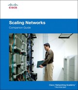
EIGRP has the capability to route several different protocols, including IPv4 and IPv6, using protocol-dependent modules (PDM). Although now obsolete, EIGRP also used PDMs to route Novell’s IPX and Apple Computer’s AppleTalk network layer protocols. EIGRP maintains three tables for each protocol, as shown in Figure 7-2.
PDMs are responsible for network layer protocol-specific tasks. An example is the EIGRP module that is responsible for sending and receiving EIGRP packets that are encapsulated in IPv4. This module is also responsible for parsing EIGRP packets and informing DUAL of the new information that is received. EIGRP asks DUAL to make routing decisions, but the results are stored in the IPv4 routing table.
PDMs are responsible for the specific routing tasks for each network layer protocol, including
![]() Maintaining the neighbor and topology tables of EIGRP routers that belong to that protocol suite
Maintaining the neighbor and topology tables of EIGRP routers that belong to that protocol suite
![]() Building and translating protocol-specific packets for DUAL
Building and translating protocol-specific packets for DUAL
![]() Interfacing DUAL to the protocol-specific routing table
Interfacing DUAL to the protocol-specific routing table
![]() Computing the metric and passing this information to DUAL
Computing the metric and passing this information to DUAL
![]() Implementing filtering and access lists
Implementing filtering and access lists
![]() Performing redistribution functions to and from other routing protocols
Performing redistribution functions to and from other routing protocols
![]() Redistributing routes that are learned by other routing protocols
Redistributing routes that are learned by other routing protocols
When a router discovers a new neighbor, it records the neighbor’s address and interface as an entry in the neighbor table. One neighbor table exists for each protocol-dependent module, such as IPv4. EIGRP also maintains a topology table. The topology table contains all destinations that are advertised by neighboring routers. There is also a separate topology table for each PDM.
Reliable Transport Protocol (7.1.1.3)
EIGRP uses Reliable Transport Protocol (RTP) for the delivery and reception of EIGRP packets. EIGRP was designed as a network layer independent routing protocol; because of this design, EIGRP cannot use the services of UDP or TCP. This allows EIGRP to be used for protocols other than those from the TCP/IP protocol suite, such as IPX and AppleTalk. Figure 7-3 conceptually shows how RTP operates.

Although “reliable” is part of its name, RTP includes both reliable delivery and unreliable delivery of EIGRP packets, similar to TCP and UDP, respectively. Reliable RTP requires an acknowledgment to be returned by the receiver to the sender. An unreliable RTP packet does not require an acknowledgment. For example, an EIGRP update packet is sent reliably over RTP and requires an acknowledgment. An EIGRP Hello packet is also sent over RTP, but unreliably. This means that EIGRP Hello packets do not require an acknowledgment.
RTP can send EIGRP packets as unicast or multicast.
![]() Multicast EIGRP packets for IPv4 use the reserved IPv4 multicast address 224.0.0.10.
Multicast EIGRP packets for IPv4 use the reserved IPv4 multicast address 224.0.0.10.
![]() Multicast EIGRP packets for IPv6 are sent to the reserved IPv6 multicast address FF02::A.
Multicast EIGRP packets for IPv6 are sent to the reserved IPv6 multicast address FF02::A.
Authentication (7.1.1.4)
RIPv2, EIGRP, OSPF, IS-IS, and BGP can each be configured to authenticate their routing information.
It is a good practice to authenticate transmitted routing information. Doing so ensures that routers only accept routing information from other routers that have been configured with the same password or authentication information.
Types of EIGRP Packets (7.1.2)
EIGRP uses five messages to communicate with other EIGRP routers in the network.
EIGRP Packet Types (7.1.2.1)
EIGRP uses five different packet types, some in pairs. EIGRP packets are sent using either RTP reliable or unreliable delivery and can be sent as a unicast, multicast, or sometimes both. EIGRP packet types are also called EIGRP packet formats or EIGRP messages. Table 7-1 lists and describes the five EIGRP packet types.

Hello packets: Used for neighbor discovery and to maintain neighbor adjacencies.
![]() Sent with unreliable delivery
Sent with unreliable delivery
![]() Multicast (on most network types)
Multicast (on most network types)
Update packets: Propagate routing information to EIGRP neighbors.
![]() Sent with reliable delivery
Sent with reliable delivery
![]() Unicast or multicast
Unicast or multicast
Acknowledgment packets: Used to acknowledge the receipt of an EIGRP message that was sent using reliable delivery.
![]() Sent with unreliable delivery
Sent with unreliable delivery
![]() Unicast
Unicast
Query packets: Used to query routes from neighbors.
![]() Sent with reliable delivery
Sent with reliable delivery
![]() Unicast or multicast
Unicast or multicast
Reply packets: Sent in response to an EIGRP query.
![]() Sent with unreliable delivery
Sent with unreliable delivery
![]() Unicast
Unicast
Figure 7-4 shows that EIGRP messages are typically encapsulated in IPv4 or IPv6 packets.

EIGRP for IPv4 messages use IPv4 as the network layer protocol. The IPv4 protocol field uses 88 to indicate that the data portion of the packet is an EIGRP for IPv4 message. EIGRP for IPv6 messages are encapsulated in IPv6 packets using the next header field of 88. Similar to the protocol field for IPv4, the IPv6 next header field indicates the type of data carried in the IPv6 packet.
EIGRP Hello Packets (7.1.2.2)
EIGRP uses small Hello packets to discover other EIGRP-enabled routers on directly connected links. Hello packets are used by routers to form EIGRP neighbor adjacencies, also known as neighbor relationships.
EIGRP Hello packets are sent as IPv4 or IPv6 multicasts, and use RTP unreliable delivery. This means that the receiver does not reply with an acknowledgment packet.
![]() The reserved EIGRP multicast address for IPv4 is 224.0.0.10.
The reserved EIGRP multicast address for IPv4 is 224.0.0.10.
![]() The reserved EIGRP multicast address for IPv6 is FF02::A.
The reserved EIGRP multicast address for IPv6 is FF02::A.
EIGRP routers discover neighbors and establish adjacencies with neighbor routers using the Hello packet. On most networks, EIGRP Hello packets are sent as multicast packets every five seconds. However, on multipoint, nonbroadcast multiple access (NBMA) networks, such as X.25, Frame Relay, and Asynchronous Transfer Mode (ATM) interfaces with access links of T1 (1.544 Mb/s) or slower, Hello packets are sent as unicast packets every 60 seconds. The default Hello intervals and hold timers are shown in Table 7-2.

EIGRP also uses Hello packets to maintain established adjacencies. An EIGRP router assumes that as long as it receives Hello packets from a neighbor, the neighbor and its routes remain viable.
EIGRP uses a Hold timer to determine the maximum time the router should wait to receive the next Hello before declaring that neighbor as unreachable. By default, the hold time is three times the Hello interval, or 15 seconds on most networks and 180 seconds on low-speed NBMA networks. If the hold time expires, EIGRP declares the route as down and DUAL searches for a new path by sending out queries.
EIGRP Update and Acknowledgment Packets (7.1.2.3)
The first two packets discussed are Update and Acknowledgment packets.
EIGRP Update Packets
EIGRP sends Update packets to propagate routing information. Update packets are sent only when necessary. EIGRP updates contain only the routing information needed and are sent only to those routers that require it.
Unlike RIP, EIGRP (another distance vector routing protocol) does not send periodic updates and route entries do not age out. Instead, EIGRP sends incremental updates only when the state of a destination changes. This can include when a new network becomes available, an existing network becomes unavailable, or a change occurs in the routing metric for an existing network.
EIGRP uses the terms partial and bounded when referring to its updates. The term partial means that the update only includes information about the route changes. The term bounded refers to the propagation of partial updates that are sent only to those routers that the changes affect.
By sending only the routing information that is needed only to those routers that need it, EIGRP minimizes the bandwidth that is required to send EIGRP updates.
EIGRP update packets use reliable delivery, which means that the sending router requires an acknowledgment. Update packets are sent as a multicast when required by multiple routers, or as a unicast when required by only a single router. In Figure 7-5, because the links are point-to-point, the updates are sent as unicasts.

EIGRP Acknowledgment Packets
EIGRP sends Acknowledgment (ACK) packets when reliable delivery is used. An EIGRP acknowledgment is an EIGRP Hello packet without any data. RTP uses reliable delivery for EIGRP update, query, and reply packets. EIGRP acknowledgment packets are always sent as an unreliable unicast. Unreliable delivery makes sense; otherwise, there would be an endless loop of acknowledgments.
In Figure 7-5, R2 has lost connectivity to the LAN attached to its Gigabit Ethernet interface. R2 immediately sends an update to R1 and R3 noting the downed route. R1 and R3 respond with an acknowledgment to let R2 know that they have received the update.
EIGRP Query and Reply Packets (7.1.2.4)
The next two EIGRP packet types discussed are Query and Reply packets.
EIGRP Query Packets
DUAL uses Query and Reply packets when searching for networks and other tasks. Queries and replies use reliable delivery. Queries can use multicast or unicast, whereas replies are always sent as unicast. In Figure 7-6, R2 has lost connectivity to the LAN and it sends out queries to all EIGRP neighbors searching for any possible routes to the LAN.

Because queries use reliable delivery, the receiving router must return an EIGRP acknowledgment. The acknowledgment informs the sender of the query that it has received the query message. To keep this example simple, acknowledgments were omitted in the graphic.
EIGRP Reply Packets
All neighbors must send a reply, regardless of whether they have a route to the downed network. Because replies also use reliable delivery, routers such as R2 must send an acknowledgment.
It might not be obvious why R2 would send out a query for a network it knows is down. Actually, only R2’s interface that is attached to the network is down. Another router could be attached to the same LAN and have an alternate path to this same network. Therefore, R2 queries for such a router before completely removing the network from its topology table.
![]() Activity 7.1.2.5: Identify the EIGRP Packet Type
Activity 7.1.2.5: Identify the EIGRP Packet Type
Go to the course online to perform this practice activity.
 Video Demonstration 7.1.2.6: Observing EIGRP Protocol Communications
Go to the course online to view this video.
EIGRP Messages (7.1.3)
This topic discusses how the EIGRP message is encapsulated and the specific fields inside EIGRP messages.
Encapsulating EIGRP Messages (7.1.3.1)
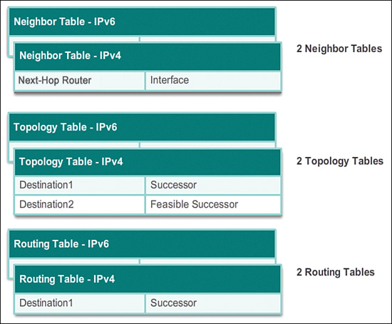
The data portion of an EIGRP message is encapsulated in a packet. This data field is called type, length, value (TLV). The types of TLVs relevant to this course are EIGRP parameters, IP internal routes, and IP external routes.
The EIGRP packet header is included with every EIGRP packet, regardless of its type. The EIGRP packet header and TLV are then encapsulated in an IPv4 packet. In the IPv4 packet header, the protocol field is set to 88 to indicate EIGRP, and the IPv4 destination address is set to the multicast 224.0.0.10. If the EIGRP packet is encapsulated in an Ethernet frame, the destination MAC address is also a multicast address, 01-00-5E-00-00-0A.
Figure 7-7 shows the Data Link Ethernet Frame. EIGRP for IPv4 is encapsulated in an IPv4 packet. EIGRP for IPv6 would use a similar type of encapsulation. EIGRP for IPv6 is encapsulated using an IPv6 header. The IPv6 destination address would be the multicast address FF02::A, and the next header field would be set to 88.
EIGRP Packet Header and TLV (7.1.3.2)
Every EIGRP message includes the header, as shown in Figure 7-8.

Important fields include the Opcode field and the Autonomous System Number field. Opcode specifies the EIGRP packet type as follows:
![]() Update
Update
![]() Query
Query
![]() Reply
Reply
![]() Hello
Hello
The autonomous system number specifies the EIGRP routing process. Unlike RIP, multiple instances of EIGRP can run on a network; the autonomous system number is used to track each running EIGRP process.
Figure 7-9 shows the EIGRP parameter’s TLV.

The EIGRP parameter’s message includes the weights that EIGRP uses for its composite metric. By default, only bandwidth and delay are weighted. Both are weighted equally; therefore, the K1 field for bandwidth and the K3 field for delay are both set to 1. The other K values are set to 0.
The Hold Time is the amount of time the EIGRP neighbor receiving this message should wait before considering the advertising router to be down.
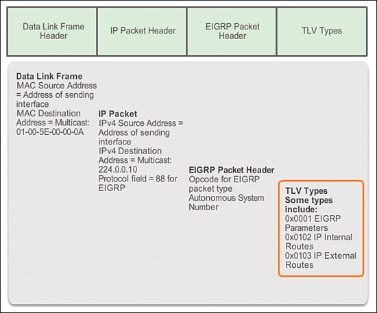
Figure 7-10 shows the IP Internal Routes TLV.
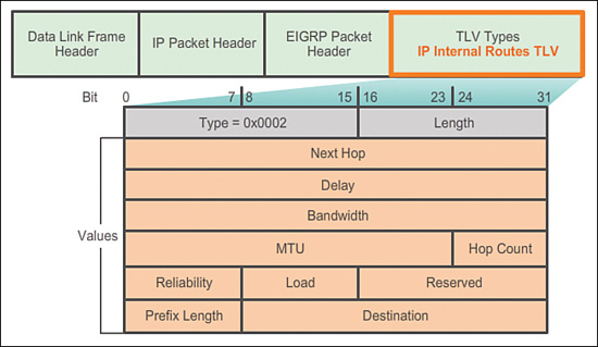
The IP internal message is used to advertise EIGRP routes within an autonomous system. Important fields include the metric fields (delay and bandwidth), the subnet mask field (prefix length), and the destination field.
Delay is calculated as the sum of delays from source to destination in units of 10 microseconds. Bandwidth is the lowest configured bandwidth of any interface along the route.
The subnet mask is specified as the prefix length or the number of network bits in the subnet mask. For example, the prefix length for the subnet mask 255.255.255.0 is 24, because 24 is the number of network bits.
The Destination field stores the address of the destination network. Although only 24 bits are shown in this figure, this field varies based on the value of the network portion of the 32-bit network address. For example, the network portion of 10.1.0.0/16 is 10.1; therefore, the Destination field stores the first 16 bits. Because the minimum length of this field is 24 bits, the remainder of the field is padded with 0s. If a network address is longer than 24 bits (192.168.1.32/27, for example), the Destination field is extended for another 32 bits (for a total of 56 bits) and the unused bits are padded with 0s.
Figure 7-11 shows the IP External Routes TLV.

The IP external message is used when external routes are imported into the EIGRP routing process. In this chapter, we will import or redistribute a default static route into EIGRP. Notice that the bottom half of the IP External Routes TLV includes all the fields used by the IP Internal TLV.
The maximum transmission unit (MTU) is not a metric used by EIGRP. The MTU is included in the routing updates, but it is not used to determine the routing metric.
Configuring EIGRP for IPv4 (7.2)
The section discusses the configuration and verification of EIGRP for IPv4.
Configuring EIGRP with IPv4 (7.2.1)
Configuring EIGRP for IPv4 can be done very quickly with a few commands. However, this topic also discusses configuring the router ID and setting interfaces as passive.
EIGRP Network Topology (7.2.1.1)
Figure 7-12 displays the topology that is used in this course to configure EIGRP for IPv4.

The types of serial interfaces and their associated bandwidths might not necessarily reflect the more common types of connections found in today’s networks. The bandwidths of the serial links used in this topology were chosen to help explain the calculation of the routing protocol metrics and the process of best path selection.
The routers in the topology have a starting configuration, including addresses on the interfaces. There is currently no static routing or dynamic routing configured on any of the routers.
Example 7-1 shows the interface configurations for the three EIGRP routers in the topology. Only Routers R1, R2, and R3 are part of the EIGRP routing domain. The ISP router is used as the routing domain’s gateway to the Internet.
Example 7-1 Interface Configurations
R1# show running-config
<Output omitted>
!
interface GigabitEthernet0/0
ip address 172.16.1.1 255.255.255.0
!
interface Serial0/0/0
ip address 172.16.3.1 255.255.255.252
clock rate 64000
!
interface Serial0/0/1
ip address 192.168.10.5 255.255.255.252
!![]()
R2# show running-config
<Output omitted>
!
interface GigabitEthernet0/0
ip address 172.16.2.1 255.255.255.0
!
interface Serial0/0/0
ip address 172.16.3.2 255.255.255.252
!
interface Serial0/0/1
ip address 192.168.10.9 255.255.255.252
clock rate 64000
!
interface Serial0/1/0
ip address 209.165.200.225 255.255.255.224
!![]()
R3# show running-config
<Output omitted>
!
interface GigabitEthernet0/0
ip address 192.168.1.1 255.255.255.0
!
interface Serial0/0/0
ip address 192.168.10.6 255.255.255.252
clock rate 64000
!
interface Serial0/0/1
ip address 192.168.10.10 255.255.255.252
!
Autonomous System Numbers (7.2.1.2)
EIGRP uses the router eigrp autonomous-system command to enable the EIGRP process. The autonomous system number referred to in the EIGRP configuration is not associated with the Internet Assigned Numbers Authority (IANA) globally assigned autonomous system numbers used by external routing protocols.
So what is the difference between the IANA globally assigned autonomous system number and the EIGRP autonomous system number?
An IANA globally assigned autonomous system is a collection of networks under the administrative control of a single entity that presents a common routing policy to the Internet. In Figure 7-13, companies A, B, C, and D are all under the administrative control of ISP1. ISP1 presents a common routing policy for all these companies when advertising routes to ISP2.

The guidelines for the creation, selection, and registration of an autonomous system are described in RFC 1930. Global autonomous system numbers are assigned by IANA, the same authority that assigns IP address space. The local regional Internet registry (RIR) is responsible for assigning an autonomous system number to an entity from its block of assigned autonomous system numbers. Prior to 2007, autonomous system numbers were 16-bit numbers ranging from 0 to 65,535. Today, 32-bit autonomous system numbers are assigned, increasing the number of available autonomous system numbers to over 4 billion.
Usually Internet Service Providers (ISPs), Internet backbone providers, and large institutions connecting to other entities require an autonomous system number. These ISPs and large institutions use the exterior gateway routing protocol Border Gateway Protocol (BGP) to propagate routing information. BGP is the only routing protocol that uses an actual autonomous system number in its configuration.
The vast majority of companies and institutions with IP networks do not need an autonomous system number, because they are controlled by a larger entity, such as an ISP. These companies use interior gateway protocols, such as RIP, EIGRP, OSPF, and IS-IS to route packets within their own networks. They are one of many independent and separate networks within the autonomous system of the ISP. The ISP is responsible for the routing of packets within its autonomous system and between other autonomous systems.
The autonomous system number used for EIGRP configuration is only significant to the EIGRP routing domain. It functions as a process ID to help routers keep track of multiple, running instances of EIGRP. This is required because it is possible to have more than one instance of EIGRP running on a network. Each instance of EIGRP can be configured to support and exchange routing updates for different networks.
The Router EIGRP Command (7.2.1.3)
The Cisco IOS includes the processes to enable and configure several different types of dynamic routing protocols. The router global configuration mode command is used to begin the configuration of any dynamic routing protocol. The topology shown in Figure 7-12 is used to demonstrate this command. As shown in Example 7-2, when followed by a question mark (?), the router global configuration mode command lists all the available routing protocols supported by this specific IOS release running on the router.
Example 7-2 Router Configuration Command
R1# conf t
Enter configuration commands, one per line. End with CNTL/Z.
R1(config)# router ?
bgp Border Gateway Protocol (BGP)
eigrp Enhanced Interior Gateway Routing Protocol (EIGRP)
isis ISO IS-IS
iso-igrp IGRP for OSI networks
lisp Locator/ID Separation Protocol
mobile Mobile routes
odr On Demand stub Routes
ospf Open Shortest Path First (OSPF)
rip Routing Information Protocol (RIP)
R1(config)# router
The following global configuration mode command is used to enter the router configuration mode for EIGRP and begin the configuration of the EIGRP process:
Router(config)# router eigrp autonomous-system
The autonomous-system argument can be assigned to any 16-bit value between the number 1 and 65,535. All routers within the EIGRP routing domain must use the same autonomous system number.
Example 7-3 shows the configuration of the EIGRP process on Routers R1, R2, and R3. Notice that the prompt changes from a global configuration mode prompt to router configuration mode.
Example 7-3 Router Configuration Command for All Three Routers
R1(config)# router eigrp 1
R1(config-router)#![]()
R2(config)# router eigrp 1
R2(config-router)#![]()
R3(config)# router eigrp 1
R3(config-router)#
In this example, 1 identifies this particular EIGRP process running on this router. To establish neighbor adjacencies, EIGRP requires all routers in the same routing domain to be configured with the same autonomous system number, as shown in Example 7-3.
Both EIGRP and OSPF can support multiple instances of each routing protocol, although this type of multiple routing protocol implementation is not usually needed or recommended.
The router eigrp autonomous-system command does not start the EIGRP process itself. The router does not start sending updates. Rather, this command only provides access to configure the EIGRP settings.
To completely remove the EIGRP routing process from a device, use the no router eigrp autonomous-system global configuration mode command, which stops the EIGRP process and removes all existing EIGRP router configurations.
EIGRP Router ID (7.2.1.4)
The EIGRP router ID is used to uniquely identify each router in the EIGRP routing domain. The router ID is used in both EIGRP and OSPF routing protocols, although the role of the router ID is more significant in OSPF.
In EIGRP IPv4 implementations, the use of the router ID is not that apparent. EIGRP for IPv4 uses the 32-bit router ID to identify the originating router for redistribution of external routes. The need for a router ID becomes more evident in the discussion of EIGRP for IPv6. While the router ID is necessary for redistribution, the details of EIGRP redistribution are beyond the scope of this curriculum. For purposes of this curriculum, it is only necessary to understand what the router ID is and how it is derived.
Determining the Router ID
Cisco routers derive the router ID based on three criteria, in the following precedence:
1. Use the IPv4 address configured with the eigrp router-id router configuration mode command.
2. If the router ID is not configured, the router chooses the highest IPv4 address of any of its loopback interfaces.
3. If no loopback interfaces are configured, the router chooses the highest active IPv4 address of any of its physical interfaces.
If the network administrator does not explicitly configure a router ID using the eigrp router-id command, EIGRP generates its own router ID using either a loopback or physical IPv4 address. A loopback address is a virtual interface and is automatically in the up state when configured. The interface does not need to be enabled for EIGRP, meaning that it does not need to be included in one of the EIGRP network commands. However, the interface must be in the up/up state.
Using the criteria previously described, Figure 7-14 shows the default EIGRP router IDs that are determined by the routers’ highest active IPv4 address.

The eigrp router-id command is used to configure the router ID for EIGRP. Some versions of IOS will accept the command router-id, without first specifying eigrp. The running config, however, will display eigrp router-id regardless of which command is used.
Configuring the EIGRP Router ID (7.2.1.5)
The eigrp router-id command is used to configure the EIGRP router ID and takes precedence over any loopback or physical interface IPv4 addresses. The command syntax is
Router(config)# router eigrp autonomous-system
Router(config-router)# eigrp router-id ipv4-address
The IPv4 address used to indicate the router ID is actually any 32-bit number displayed in dotted-decimal notation.
The router ID can be configured with any IPv4 address with two exceptions: 0.0.0.0 and 255.255.255.255. The router ID should be a unique 32-bit number in the EIGRP routing domain; otherwise, routing inconsistencies can occur.
Loopback Address Used as the Router ID
Another option to specify the EIGRP router ID is to use an IPv4 loopback address. The advantage of using a loopback interface, instead of the IPv4 address of a physical interface, is that unlike physical interfaces, it cannot fail. There are no actual cables or adjacent devices on which the loopback interface depends for being in the up state. Therefore, using a loopback address for the router ID can provide a more consistent router ID than using an interface address.
If the eigrp router-id command is not used and loopback interfaces are configured, EIGRP chooses the highest IPv4 address of any of its loopback interfaces. The following commands are used to enable and configure a loopback interface:
Router(config)# interface loopback number
Router(config-if)# ip address ipv4-address subnet-mask
The EIGRP router ID is not changed unless the EIGRP process is removed with the no router eigrp command or if the router ID is manually configured with the eigrp router-id command.
Example 7-4 shows the configuration of the router ID for the routers in Figure 7-14.
Example 7-4 Configuring and Verifying the EIGRP Router ID
R1(config)# router eigrp 1
R1(config-router)# eigrp router-id 1.1.1.1
R1(config-router)#![]()
R2(config)# router eigrp 1
R2(config-router)# eigrp router-id 2.2.2.2
R2(config-router)#![]()
R3(config)# router eigrp 1
R3(config-router)# eigrp router-id 3.3.3.3
R3(config-router)# end
R3# show ip protocols
*** IP Routing is NSF aware ***
Routing Protocol is "eigrp 1"
<Output omitted>
EIGRP-IPv4 Protocol for AS(1)
Metric weight K1=1, K2=0, K3=1, K4=0, K5=0
NSF-aware route hold timer is 240
Router-ID: 3.3.3.3
Topology : 0 (base)
Active Timer: 3 min
Distance: internal 90 external 170
<Output omitted>
Verifying the EIGRP Process
Example 7-4 displays the show ip protocols output for R3, including its router ID. The show ip protocols command displays the parameters and current state of any active routing protocol processes, including both EIGRP and OSPF. The show ip protocols command displays different types of output specific to each routing protocol.
The network Command (7.2.1.6)
EIGRP router configuration mode allows for the configuration of the EIGRP routing protocol. Figure 7-12 shows that R1, R2, and R3 all have networks that should be included within a single EIGRP routing domain. To enable EIGRP routing on an interface, use the network router configuration mode command and enter the classful network address for each directly connected network.
The network command has the same function as in all IGP routing protocols. The network command in EIGRP
![]() Enables any interface on this router that matches the network address in the network router configuration mode command to send and receive EIGRP updates
Enables any interface on this router that matches the network address in the network router configuration mode command to send and receive EIGRP updates
![]() The network of the interfaces is included in EIGRP routing updates.
The network of the interfaces is included in EIGRP routing updates.
The network command in EIGRP is as follows:
Router(config-router)# network ipv4-network-address
The ipv4-network-address argument is the classful IPv4 network address for this interface. Figure 7-15 shows the network commands configured for R1.

In the figure, a single classful network statement, network 172.16.0.0, is used on R1 to include both interfaces in subnets 172.16.1.0/24 and 172.16.3.0/30. Notice that only the classful network address is used.
Example 7-5 shows the network command used to enable EIGRP on R2’s interfaces for subnets 172.16.1.0/24 and 172.16.2.0/24.
Example 7-5 EIGRP Neighbor Adjacency Message
R2(config)# router eigrp 1
R2(config-router)# network 172.16.0.0
R2(config-router)#
*Feb 28 17:51:42.543: %DUAL-5-NBRCHANGE: EIGRP-IPv4 1: Neighbor 172.16.3.1
(Serial0/0/0) is up: new adjacency
R2(config-router)#
When EIGRP is configured on R2’s S0/0/0 interface, DUAL sends a notification message to the console stating that a neighbor adjacency with another EIGRP router on that interface has been established. This new adjacency happens automatically because both R1 and R2 use the same eigrp 1 autonomous system number, and both routers now send updates on their interfaces in the 172.16.0.0 network.
By default, the eigrp log-neighbor-changes router configuration mode command is enabled. This command is used to
![]() Display any changes in EIGRP neighbor adjacencies
Display any changes in EIGRP neighbor adjacencies
![]() Help verify neighbor adjacencies during configuration of EIGRP
Help verify neighbor adjacencies during configuration of EIGRP
![]() Advise the network administrator when any EIGRP adjacencies have been removed
Advise the network administrator when any EIGRP adjacencies have been removed
The network Command and Wildcard Mask (7.2.1.7)
By default, when using the network command and an IPv4 network address, such as 172.16.0.0, all interfaces on the router that belong to that classful network address are enabled for EIGRP. However, there can be times when the network administrator does not want to include all interfaces within a network when enabling EIGRP. For example, in Figure 7-16, assume that an administrator wants to enable EIGRP on R2, but only for the subnet 192.168.10.8 255.255.255.252, on the S0/0/1 interface.

To configure EIGRP to advertise specific subnets only, use the wildcard-mask option with the network command:
Router(config-router)# network network-address [wildcard-mask]
Think of a wildcard mask as the inverse of a subnet mask. The inverse of subnet mask 255.255.255.252 is 0.0.0.3. To calculate the inverse of the subnet mask, subtract the subnet mask from 255.255.255.255 as follows:
255.255.255.255
- 255.255.255.252
---------------
0. 0. 0. 3 Wildcard mask
Figure 7-17 continues the EIGRP network configuration of R2.

The network 192.168.10.8 0.0.0.3 command specifically enables EIGRP on the S0/0/1 interface, a member of the 192.168.10.8 255.255.255.252 subnet.
Some IOS versions also let you enter the subnet mask instead of a wildcard mask. Example 7-6 shows an example of configuring the same S0/0/1 interface on R2, but this time using a subnet mask in the network command.
Example 7-6 Alternative network Command Configuration Using a Subnet Mask
R2(config)# router eigrp 1
R2(config-router)# network 192.168.10.8 255.255.255.252
R2(config-router)# end
R2# show running-config | section eigrp 1
router eigrp 1
network 172.16.0.0
network 192.168.10.8 0.0.0.3
eigrp router-id 2.2.2.2
R2#
However, if the subnet mask is used, the IOS converts the command to the wildcard-mask format within the configuration. This is verified in the show running-config output in Example 7-6.
Example 7-7 shows the EIGRP configuration for Router R3.
Example 7-7 Configuring the network Command and Wildcard Mask on R3
R3(config)# router eigrp 1
R3(config-router)# network 192.168.1.0
R3(config-router)# network 192.168.10.4 0.0.0.3
*Feb 28 20:47:22.695: %DUAL-5-NBRCHANGE: EIGRP-IPv4 1: Neighbor 192.168.10.5
(Serial0/0/0) is up: new adjacency
R3(config-router)# network 192.168.10.8 0.0.0.3
*Feb 28 20:47:06.555: %DUAL-5-NBRCHANGE: EIGRP-IPv4 1: Neighbor 192.168.10.9
(Serial0/0/1) is up: new adjacency
R3(config-router)#
Passive Interface (7.2.1.8)
As soon as a new interface is enabled within the EIGRP network, EIGRP attempts to form a neighbor adjacency with any neighboring routers to send and receive EIGRP updates.
At times it might be necessary, or advantageous, to include a directly connected network in the EIGRP routing update, but not allow any neighbor adjacencies connected to that interface to form. The passive-interface command can be used to prevent the neighbor adjacencies. There are two primary reasons for enabling the passive-interface command:
![]() To suppress unnecessary update traffic, such as when an interface is a LAN interface, with no other routers connected
To suppress unnecessary update traffic, such as when an interface is a LAN interface, with no other routers connected
![]() To increase security controls, such as preventing unknown rogue routing devices from receiving EIGRP updates
To increase security controls, such as preventing unknown rogue routing devices from receiving EIGRP updates
Figure 7-18 shows that R1, R2, and R3 do not have EIGRP neighbors on their GigabitEthernet 0/0 interfaces. Yet, each router is still sending out a Hello message every 5 seconds.

The passive-interface router configuration mode command disables the transmission and receipt of EIGRP Hello packets on these interfaces.
Router(config)# router eigrp as-number
Router(config-router)# passive-interface interface-type interface-number
Example 7-8 shows the passive-interface command configured to suppress Hello packets on the LANs for all three routers.
Example 7-8 Configuring and Verifying EIGRP Passive Interfaces
R1(config)# router eigrp 1
R1(config-router)# passive-interface gigabitethernet 0/0![]()
R3(config)# router eigrp 1
R3(config-router)# passive-interface gigabitethernet 0/0![]()
R2(config)# router eigrp 1
R2(config-router)# passive-interface gigabitethernet 0/0
R2(config-router)# end
R2# show ip protocols
*** IP Routing is NSF aware ***
Routing Protocol is "eigrp 1"
Outgoing update filter list for all interfaces is not set
Incoming update filter list for all interfaces is not set
Default networks flagged in outgoing updates
Default networks accepted from incoming updates
Redistributing: static
EIGRP-IPv4 Protocol for AS(1)
Metric weight K1=1, K2=0, K3=1, K4=0, K5=0
NSF-aware route hold timer is 240
Router-ID: 2.2.2.2
Topology : 0 (base)
Active Timer: 3 min
Distance: internal 90 external 170
Maximum path: 4
Maximum hopcount 100
Maximum metric variance 1
Automatic Summarization: disabled
Maximum path: 4
Routing for Networks:
172.16.0.0
192.168.10.8/30
Passive Interface(s):
GigabitEthernet0/0
Routing Information Sources:
Gateway Distance Last Update
192.168.10.10 90 02:14:28
172.16.3.1 90 02:14:28
Distance: internal 90 external 170
R2#
Without a neighbor adjacency, EIGRP cannot exchange routes with a neighbor. Therefore, the passive-interface command prevents the exchange of routes on the interface. Although EIGRP does not send or receive routing updates on an interface configured with the passive-interface command, it still includes the address of the interface in routing updates sent out of other nonpassive interfaces.
To configure all interfaces as passive, use the passive-interface default command. To disable an interface as passive, use the no passive-interface interface-type interface-number command.
An example of using the passive interface to increase security controls is when a network must connect to a third-party organization for which the local administrator has no control, such as when connecting to an ISP network. In this case, the local network administrator would need to advertise the interface link through his own network, but would not want the third-party organization to receive or send routing updates to the local routing device, as this is a security risk.
Verifying the Passive Interface
To verify whether any interface on a router is configured as passive, use the show ip protocols privileged EXEC mode command, as shown in Example 7-8. Notice that although R3’s GigabitEthernet 0/0 interface is a passive interface, EIGRP still includes the interface’s network address of 192.168.1.0 in its routing updates.
Verifying EIGRP with IPv4 (7.2.2)
This topic discusses the verification commands unique to EIGRP as well as examines EIGRP routes in the routing table.
Verifying EIGRP: Examining Neighbors (7.2.2.1)
Before EIGRP can send or receive any updates, routers must establish adjacencies with their neighbors. EIGRP routers establish adjacencies with neighbor routers by exchanging EIGRP Hello packets.
As shown in Figure 7-19, use the show ip eigrp neighbors command to view the neighbor table and verify that EIGRP has established an adjacency with its neighbors.

For each router, you should be able to see the IPv4 address of the adjacent router and the interface that this router uses to reach that EIGRP neighbor. Using this topology, each router has two neighbors listed in the neighbor table.
The show ip eigrp neighbors command output includes
![]() H column: Lists the neighbors in the order that they were learned.
H column: Lists the neighbors in the order that they were learned.
![]() Address: IPv4 address of the neighbor.
Address: IPv4 address of the neighbor.
![]() Interface: Local interface on which this Hello packet was received.
Interface: Local interface on which this Hello packet was received.
![]() Hold: Current hold time. When a Hello packet is received, this value is reset to the maximum hold time for that interface, and then counts down to 0. If 0 is reached, the neighbor is considered down.
Hold: Current hold time. When a Hello packet is received, this value is reset to the maximum hold time for that interface, and then counts down to 0. If 0 is reached, the neighbor is considered down.
![]() Uptime: Amount of time since this neighbor was added to the neighbor table.
Uptime: Amount of time since this neighbor was added to the neighbor table.
![]() Smooth Round Trip Timer (SRTT) and Retransmission Timeout (RTO): Used by RTP to manage reliable EIGRP packets.
Smooth Round Trip Timer (SRTT) and Retransmission Timeout (RTO): Used by RTP to manage reliable EIGRP packets.
![]() Queue Count: Should always be 0. If more than 0, EIGRP packets wait to be sent.
Queue Count: Should always be 0. If more than 0, EIGRP packets wait to be sent.
![]() Sequence Number: Used to track updates, queries, and reply packets.
Sequence Number: Used to track updates, queries, and reply packets.
The show ip eigrp neighbors command is very useful for verifying and troubleshooting EIGRP. If a neighbor is not listed after adjacencies have been established with a router’s neighbors, check the local interface to ensure that it is activated with the show ip interface brief command. If the interface is active, try pinging the IPv4 address of the neighbor. If the ping fails, it means that the neighbor interface is down and must be activated. If the ping is successful and EIGRP still does not see the router as a neighbor, examine the following configurations:
![]() Are both routers configured with the same EIGRP autonomous system number?
Are both routers configured with the same EIGRP autonomous system number?
![]() Is the directly connected network included in the EIGRP network statements?
Is the directly connected network included in the EIGRP network statements?
Verifying EIGRP: show ip protocols Command (7.2.2.2)
As shown in Figure 7-20, the show ip protocols command displays the parameters and other information about the current state of any active IPv4 routing protocol processes configured on the router.

The show ip protocols command displays different types of output specific to each routing protocol.
The output in Figure 7-20 indicates several EIGRP parameters, including
1. EIGRP is an active dynamic routing protocol on R1 configured with the autonomous system number 1.
2. The EIGRP router ID of R1 is 1.1.1.1.
3. The EIGRP administrative distances on R1 are internal AD of 90 and external of 170 (default values).
4. By default, EIGRP does not automatically summarize networks. Subnets are included in the routing updates.
5. The Routing Information Sources are EIGRP neighbor adjacencies that indicate from which routers R1 will receive EIGRP routing updates.
The output from the show ip protocols command is useful in debugging routing operations. Information in the Routing Information Sources field can help identify a router suspected of delivering bad routing information. The Routing Information Sources field lists all the EIGRP routing sources that the Cisco IOS Software uses to build its IPv4 routing table. For each source, note the following:
![]() IPv4 address
IPv4 address
![]() Administrative distance
Administrative distance
![]() Time the last update was received from this source
Time the last update was received from this source
As shown in Table 7-3, EIGRP has a default AD of 90 for internal routes and 170 for routes imported from an external source, such as default routes.

When compared to other IGPs, EIGRP is the most preferred by the Cisco IOS, because it has the lowest administrative distance. EIGRP has a third AD value of 5, for summary routes.
Verifying EIGRP: Examine the IPv4 Routing Table (7.2.2.3)
Another way to verify that EIGRP and other functions of the router are configured properly is to examine the IPv4 routing tables with the show ip route command. As with any dynamic routing protocol, the network administrator must verify the information in the routing table to ensure that it is populated as expected, based on configurations entered. For this reason, it is important to have a good understanding of the routing protocol configuration commands, as well as the routing protocol operations and the processes used by the routing protocol to build the IP routing table.
Notice that the outputs used throughout this course are from Cisco IOS Release 15. Prior to IOS Release 15, EIGRP automatic summarization was enabled by default. The state of automatic summarization can make a difference in the information displayed in the IPv4 routing table. If a previous version of the IOS is used, automatic summarization can be disabled using the no auto-summary router configuration mode command:
Router(config-router)# no auto-summary
In Example 7-9, the IPv4 routing table is examined using the show ip route command.
Example 7-9 IPv4 Routing Tables
R1# show ip route
Codes: L - local, C - connected, S - static, R - RIP, M - mobile, B - BGP
D - EIGRP, EX - EIGRP external, O - OSPF, IA - OSPF inter area
<Output omitted>
Gateway of last resort is not set
172.16.0.0/16 is variably subnetted, 5 subnets, 3 masks
C 172.16.1.0/24 is directly connected, GigabitEthernet0/0
L 172.16.1.1/32 is directly connected, GigabitEthernet0/0
D 172.16.2.0/24 [90/2170112] via 172.16.3.2, 00:14:35, Serial0/0/0
C 172.16.3.0/30 is directly connected, Serial0/0/0
L 172.16.3.1/32 is directly connected, Serial0/0/0
D 192.168.1.0/24 [90/2170112] via 192.168.10.6, 00:13:57, Serial0/0/1
192.168.10.0/24 is variably subnetted, 3 subnets, 2 masks
C 192.168.10.4/30 is directly connected, Serial0/0/1
L 192.168.10.5/32 is directly connected, Serial0/0/1
D 192.168.10.8/30 [90/2681856] via 192.168.10.6, 00:50:42, Serial0/0/1
[90/2681856] via 172.16.3.2, 00:50:42, Serial0/0/0
R1#![]()
R2# show ip route
Codes: L - local, C - connected, S - static, R - RIP, M - mobile, B - BGP
D - EIGRP, EX - EIGRP external, O - OSPF, IA - OSPF inter area
<Output omitted>
Gateway of last resort is not set
172.16.0.0/16 is variably subnetted, 5 subnets, 3 masks
D 172.16.1.0/24 [90/2170112] via 172.16.3.1, 00:11:05, Serial0/0/0
C 172.16.2.0/24 is directly connected, GigabitEthernet0/0
L 172.16.2.1/32 is directly connected, GigabitEthernet0/0
C 172.16.3.0/30 is directly connected, Serial0/0/0
L 172.16.3.2/32 is directly connected, Serial0/0/0
D 192.168.1.0/24 [90/2170112] via 192.168.10.10, 00:15:16, Serial0/0/1
192.168.10.0/24 is variably subnetted, 3 subnets, 2 masks
D 192.168.10.4/30 [90/2681856] via 192.168.10.10, 00:52:00, Serial0/0/1
[90/2681856] via 172.16.3.1, 00:52:00, Serial0/0/0
C 192.168.10.8/30 is directly connected, Serial0/0/1
L 192.168.10.9/32 is directly connected, Serial0/0/1
209.165.200.0/24 is variably subnetted, 2 subnets, 2 masks
C 209.165.200.224/27 is directly connected, Loopback209
L 209.165.200.225/32 is directly connected, Loopback209
R2#![]()
R3# show ip route
Codes: L - local, C - connected, S - static, R - RIP, M - mobile, B - BGP
D - EIGRP, EX - EIGRP external, O - OSPF, IA - OSPF inter area
<Output omitted>
Gateway of last resort is not set
172.16.0.0/16 is variably subnetted, 3 subnets, 2 masks
D 172.16.1.0/24 [90/2170112] via 192.168.10.5, 00:12:00, Serial0/0/0
D 172.16.2.0/24 [90/2170112] via 192.168.10.9, 00:16:49, Serial0/0/1
D 172.16.3.0/30 [90/2681856] via 192.168.10.9, 00:52:55, Serial0/0/1
[90/2681856] via 192.168.10.5, 00:52:55, Serial0/0/0
192.168.1.0/24 is variably subnetted, 2 subnets, 2 masks
C 192.168.1.0/24 is directly connected, GigabitEthernet0/0
L 192.168.1.1/32 is directly connected, GigabitEthernet0/0
192.168.10.0/24 is variably subnetted, 4 subnets, 2 masks
C 192.168.10.4/30 is directly connected, Serial0/0/0
L 192.168.10.6/32 is directly connected, Serial0/0/0
C 192.168.10.8/30 is directly connected, Serial0/0/1
L 192.168.10.10/32 is directly connected, Serial0/0/1
R3#
EIGRP routes are denoted in the routing table with a D. The letter D is used to represent EIGRP because the protocol is based upon the DUAL algorithm.
The show ip route command verifies that routes received by EIGRP neighbors are installed in the IPv4 routing table. The show ip route command displays the entire routing table, including remote networks learned dynamically, directly connected, and static routes. For this reason, it is normally the first command used to check for convergence. After routing is correctly configured on all routers, the show ip route command reflects that each router has a full routing table, with a route to each network in the topology.
Notice that R1 has installed routes to three IPv4 remote networks in its IPv4 routing table:
![]() 172.16.2.0/24 network, received from Router R2 on the Serial0/0/0 interface
172.16.2.0/24 network, received from Router R2 on the Serial0/0/0 interface
![]() 192.168.1.0/24 network, received from Router R2 on the Serial0/0/1 interface
192.168.1.0/24 network, received from Router R2 on the Serial0/0/1 interface
![]() 192.168.10.8/30 network, received from both R2 on the Serial0/0/0 interface and from R3 on the Serial0/0/1 interface
192.168.10.8/30 network, received from both R2 on the Serial0/0/0 interface and from R3 on the Serial0/0/1 interface
R1 has two paths to the 192.168.10.8/30 network, because its cost or metric to reach that network is the same or equal using both routers. These are known as equal-cost routes. R1 uses both paths to reach this network, which is known as load balancing. The EIGRP metric is discussed later in this chapter.
For R2 and R3, notice that similar results are displayed, including equal-cost routes.
 Packet Tracer Activity 7.2.2.4: Configuring Basic EIGRP with IPv4
In this activity, you will implement basic EIGRP configurations including network commands, passive interfaces, and disabling automatic summarization. You will then verify your EIGRP configuration using a variety of show commands and testing end-to-end connectivity.
![]() Lab 7.2.2.5: Configuring Basic EIGRP with IPv4
Lab 7.2.2.5: Configuring Basic EIGRP with IPv4
In this lab, you will complete the following objectives:
![]() Part 1: Build the Network and Verify Connectivity
Part 1: Build the Network and Verify Connectivity
![]() Part 2: Configure EIGRP Routing
Part 2: Configure EIGRP Routing
![]() Part 3: Verify EIGRP Routing
Part 3: Verify EIGRP Routing
![]() Part 4: Configure Bandwidth and Passive Interfaces
Part 4: Configure Bandwidth and Passive Interfaces
Operation of EIGRP (7.3)
This section digs deeper into the details of EIGRP operations, including EIGRP convergence, metric calculation, and how DUAL installs and maintains the tables used by EIGRP.
EIGRP Initial Route Discovery (7.3.1)
Initial route discovery begins with forming a neighbor adjacency and proceeds from there through a series of steps until the topology table is complete.
EIGRP Neighbor Adjacency (7.3.1.1)
The goal of any dynamic routing protocol is to learn about remote networks from other routers and to reach convergence in the routing domain. Before any EIGRP update packets can be exchanged between routers, EIGRP must first discover its neighbors. EIGRP neighbors are other routers running EIGRP on directly connected networks.
EIGRP uses Hello packets to establish and maintain neighbor adjacencies. For two EIGRP routers to become neighbors, several parameters between the two routers must match. For example, two EIGRP routers must use the same EIGRP metric parameters and both must be configured using the same autonomous system number.
Each EIGRP router maintains a neighbor table, which contains a list of routers on shared links that have an EIGRP adjacency with this router. The neighbor table is used to track the status of these EIGRP neighbors.
Figure 7-21 shows two EIGRP routers exchanging initial EIGRP Hello packets.

When an EIGRP-enabled router receives a Hello packet on an interface, it adds that router to its neighbor table.
1. A new router (R1) comes up on the link and sends an EIGRP Hello packet through all its EIGRP-configured interfaces.
2. Router R2 receives the Hello packet on an EIGRP-enabled interface. R2 replies with an EIGRP update packet that contains all the routes it has in its routing table, except those learned through that interface (split horizon). However, the neighbor adjacency is not established until R2 also sends an EIGRP Hello packet to R1.
3. After both routers have exchanged Hellos, the neighbor adjacency is established. R1 and R2 update their EIGRP neighbor tables, adding the adjacent router as a neighbor.
EIGRP Topology Table (7.3.1.2)
EIGRP updates contain networks that are reachable from the router sending the update. As EIGRP updates are exchanged between neighbors, the receiving router adds these entries to its EIGRP topology table.
Each EIGRP router maintains a topology table for each routed protocol configured, such as IPv4 and IPv6. The topology table includes route entries for every destination that the router learns from its directly connected EIGRP neighbors.
Figure 7-22 shows the continuation of the initial route discovery process from the previous page.

It now shows the update of the topology table.
When a router receives an EIGRP routing update, it adds the routing information to its EIGRP topology table and replies with an EIGRP acknowledgment.
1. R1 receives the EIGRP update from neighbor R2 and includes information about the routes that the neighbor is advertising, including the metric to each destination. R1 adds all update entries to its topology table. The topology table includes all destinations advertised by neighboring (adjacent) routers and the cost (metric) to reach each network.
2. EIGRP update packets use reliable delivery; therefore, R1 replies with an EIGRP acknowledgment packet informing R2 that it has received the update.
3. R1 sends an EIGRP update to R2 advertising the routes that it is aware of, except those learned from R2 (split horizon).
4. R2 receives the EIGRP update from neighbor R1 and adds this information to its own topology table.
5. R2 responds to R1’s EIGRP update packet with an EIGRP acknowledgment.
EIGRP Convergence (7.3.1.3)
Figure 7-23 illustrates the final steps of the initial route discovery process.
1. After receiving the EIGRP update packets from R2, using the information in the topology table, R1 updates its IP routing table with the best path to each destination, including the metric and the next-hop router.
2. Similar to R1, R2 updates its IP routing table with the best path routes to each network.

At this point, EIGRP on both routers is considered to be in the converged state.
![]() Activity 7.3.1.4: Identify the Steps in Establishing EIGRP Neighbor Adjacencies
Activity 7.3.1.4: Identify the Steps in Establishing EIGRP Neighbor Adjacencies
Go to the course online to perform this practice activity.
Metrics (7.3.2)
Although EIGRP can use five different inputs to calculate a metric, it defaults to bandwidth and delay.
EIGRP Composite Metric (7.3.2.1)
By default, EIGRP uses the following values in its composite metric to calculate the preferred path to a network:
![]() Bandwidth: The slowest bandwidth among all the outgoing interfaces, along the path from source to destination.
Bandwidth: The slowest bandwidth among all the outgoing interfaces, along the path from source to destination.
![]() Delay: The cumulative (sum) of all interface delays along the path (in tens of microseconds).
Delay: The cumulative (sum) of all interface delays along the path (in tens of microseconds).
The following values can be used, but are not recommended, because they typically result in frequent recalculation of the topology table:
![]() Reliability: Represents the worst reliability between the source and destination, which is based on keepalives.
Reliability: Represents the worst reliability between the source and destination, which is based on keepalives.
![]() Load: Represents the worst load on a link between the source and destination, which is computed based on the packet rate and the configured bandwidth of the interface.
Load: Represents the worst load on a link between the source and destination, which is computed based on the packet rate and the configured bandwidth of the interface.
Although the MTU is included in the routing table updates, it is not a routing metric used by EIGRP.
The Composite Metric
Figure 7-24 shows the composite metric formula used by EIGRP.

The formula consists of values K1 to K5, known as EIGRP metric weights. K1 and K3 represent bandwidth and delay, respectively. K2 represents load, and K4 and K5 represent reliability. By default, K1 and K3 are set to 1, and K2, K4, and K5 are set to 0. The result is that only the bandwidth and delay values are used in the computation of the default composite metric. EIGRP for IPv4 and EIGRP for IPv6 use the same formula for the composite metric.
The metric calculation method (k values) and the EIGRP autonomous system number must match between EIGRP neighbors. If they do not match, the routers do not form an adjacency.
The default k values can be changed with the metric weights router configuration mode command:
Router(config-router)# metric weights tos k1 k2 k3 k4 k5
Modifying the metric weights value is generally not recommended and is beyond the scope of this course. However, its relevance is important in establishing neighbor adjacencies. If one router has modified the metric weights and another router has not, an adjacency does not form.
Verifying the k Values
The show ip protocols command is used to verify the k values. The command output for R1 is shown in Example 7-10.
Example 7-10 Verifying Metric K Values
R1# show ip protocols
*** IP Routing is NSF aware ***
Routing Protocol is "eigrp 1"
Outgoing update filter list for all interfaces is not set
Incoming update filter list for all interfaces is not set
Default networks flagged in outgoing updates
Default networks accepted from incoming updates
EIGRP-IPv4 Protocol for AS(1)
Metric weight K1=1, K2=0, K3=1, K4=0, K5=0
NSF-aware route hold timer is 240
Router-ID: 1.1.1.1
<Output omitted>
R1#
Notice that the k values on R1 are set to the default.
Examining Interface Values (7.3.2.2)
The show interfaces command displays interface information, including the parameters used to compute the EIGRP metric. Example 7-11 shows the show interface command for the Serial 0/0/0 interface on R1.
Example 7-11 Verifying Metrics with the show interface Command
R1# show interface serial 0/0/0
Serial0/0/0 is up, line protocol is up
Hardware is WIC MBRD Serial
Internet address is 172.16.3.1/30
MTU 1500 bytes, BW 1544 Kbit/sec, DLY 20000 usec,
reliability 255/255, txload 1/255, rxload 1/255
Encapsulation HDLC, loopback not set
<Output omitted>
R1# show interface gigabitethernet 0/0
GigabitEthernet0/0 is up, line protocol is up
Hardware is CN Gigabit Ethernet, address is fc99.4775.c3e0 (bia fc99.4775.c3e0)
Internet address is 172.16.1.1/24
MTU 1500 bytes, BW 100000 Kbit/sec, DLY 100 usec,
reliability 255/255, txload 1/255, rxload 1/255
Encapsulation ARPA, loopback not set
<Output omitted>
R1#
![]() BW: Bandwidth of the interface (in kilobits per second).
BW: Bandwidth of the interface (in kilobits per second).
![]() DLY: Delay of the interface (in microseconds).
DLY: Delay of the interface (in microseconds).
![]() Reliability: Reliability of the interface as a fraction of 255 (255/255 is 100% reliability), calculated as an exponential average over five minutes. By default, EIGRP does not include its value in computing its metric.
Reliability: Reliability of the interface as a fraction of 255 (255/255 is 100% reliability), calculated as an exponential average over five minutes. By default, EIGRP does not include its value in computing its metric.
![]() Txload, Rxload: Transmit and receive load on the interface as a fraction of 255 (255/255 is completely saturated), calculated as an exponential average over five minutes. By default, EIGRP does not include its value in computing its metric.
Txload, Rxload: Transmit and receive load on the interface as a fraction of 255 (255/255 is completely saturated), calculated as an exponential average over five minutes. By default, EIGRP does not include its value in computing its metric.
Throughout this course, bandwidth is referenced as kb/s. However, router output displays bandwidth using the Kbit/sec abbreviation. Router output also displays delay as µsec. In this course, delay is referenced as microseconds.
Bandwidth Metric (7.3.2.3)
The bandwidth metric is a static value used by some routing protocols, such as EIGRP and OSPF, to calculate their routing metric. The bandwidth is displayed in kilobits per second (kb/s). Most serial interfaces use the default bandwidth value of 1544 kb/s or 1,544,000 b/s (1.544 Mb/s). This is the bandwidth of a T1 connection. However, some serial interfaces use a different default bandwidth value. Figure 7-25 shows the topology now with bandwidth values labeled on the serial links.

The types of serial interfaces and their associated bandwidths might not necessarily reflect the more common types of connections found in networks today.
Always verify bandwidth with the show interfaces command.
The default value of the bandwidth might or might not reflect the actual physical bandwidth of the interface. If the actual bandwidth of the link differs from the default bandwidth value, the bandwidth value should be modified.
Configuring the Bandwidth Parameter
On most serial links, the bandwidth metric defaults to 1544 kb/s. Because both EIGRP and OSPF use bandwidth in default metric calculations, a correct value for bandwidth is very important to the accuracy of routing information.
Use the following interface configuration mode command to modify the bandwidth metric:
Router(config-if)# bandwidth kilobits-bandwidth-value
Use the no bandwidth command to restore the default value.
In Figure 7-25, the link between R1 and R2 has a bandwidth of 64 kb/s, and the link between R2 and R3 has a bandwidth of 1024 kb/s. Example 7-12 shows the configurations used on all three routers to modify the bandwidth on the appropriate serial interfaces.
Example 7-12 Bandwidth Configuration on All Three Routers
R1(config)# interface s 0/0/0
R1(config-if)# bandwidth 64![]()
R2(config)# interface s 0/0/0
R2(config-if)# bandwidth 64
R2(config-if)# exit
R2(config)# interface s 0/0/1
R2(config-if)# bandwidth 1024![]()
R3(config)# interface s 0/0/1
R3(config-if)# bandwidth 1024
Verifying the Bandwidth Parameter
Use the show interface command to verify the new bandwidth parameters, as shown in Example 7-13 for the link between R1 and R2.
Example 7-13 Verifying the Bandwidth Value
R1# show interface s 0/0/0
Serial0/0/0 is up, line protocol is up
Hardware is WIC MBRD Serial
Internet address is 172.16.3.1/30
MTU 1500 bytes, BW 64 Kbit/sec, DLY 20000 usec,
reliability 255/255, txload 1/255, rxload 1/255
<Output omitted>
R1#![]()
R2# show interface s 0/0/0
Serial0/0/0 is up, line protocol is up
Hardware is WIC MBRD Serial
Internet address is 172.16.3.2/30
MTU 1500 bytes, BW 64 Kbit/sec, DLY 20000 usec,
reliability 255/255, txload 1/255, rxload 1/255
<Output omitted>
R2#
It is important to modify the bandwidth metric on both sides of the link to ensure proper routing in both directions.
Modifying the bandwidth value does not change the actual bandwidth of the link. The bandwidth command only modifies the bandwidth metric used by routing protocols, such as EIGRP and OSPF.
Delay Metric (7.3.2.4)
Delay is the measure of the time it takes for a packet to traverse a route. The delay (DLY) metric is a static value based on the type of link to which the interface is connected and is expressed in microseconds. Delay is not measured dynamically. In other words, the router does not actually track how long packets take to reach the destination. The delay value, much like the bandwidth value, is a default value that can be changed by the network administrator.
When used to determine the EIGRP metric, delay is the cumulative (sum) of all interface delays along the path (measured in tens of microseconds).
Table 7-4 shows the default delay values for various interfaces.

Notice that the default value is 20,000 microseconds for serial interfaces and 10 microseconds for Gigabit Ethernet interfaces.
Use the show interface command to verify the delay value on an interface, as shown in Example 7-14.
Example 7-14 Verifying the Delay Value
R1# show interface s 0/0/0
Serial0/0/0 is up, line protocol is up
Hardware is WIC MBRD Serial
Internet address is 172.16.3.1/30
MTU 1500 bytes, BW 64 Kbit/sec, DLY 20000 usec,
reliability 255/255, txload 1/255, rxload 1/255
<Output omitted>
R1# show interface g 0/0
GigabitEthernet0/0 is up, line protocol is up
Hardware is CN Gigabit Ethernet, address is fc99.4775.c3e0 (bia fc99.4775.c3e0)
Internet address is 172.16.1.1/24
MTU 1500 bytes, BW 1000000 Kbit/sec, DLY 10 usec,
reliability 255/255, txload 1/255, rxload 1/255
<Output omitted>
R1#
Although an interface with various bandwidths can have the same delay value, by default, Cisco recommends not modifying the delay parameter, unless the network administrator has a specific reason to do so.
How to Calculate the EIGRP Metric (7.3.2.5)
Although EIGRP automatically calculates the routing table metric used to choose the best path, it is important that the network administrator understands how these metrics were determined. Figure 7-26 shows the composite metric used by EIGRP.

Using the default values for K1 and K3, the calculation can be simplified to the slowest bandwidth (or minimum bandwidth), plus the sum of all the delays.
In other words, by examining the bandwidth and delay values for all the outgoing interfaces of the route, we can determine the EIGRP metric as follows:
Step 1. Determine the link with the slowest bandwidth. Use that value to calculate bandwidth (10,000,000/bandwidth).
Step 2. Determine the delay value for each outgoing interface on the way to the destination. Add the delay values and divide by 10 (sum of delay/10).
Step 3. Add the computed values for bandwidth and delay, and multiply the sum by 256 to obtain the EIGRP metric.
The routing table output for R2 shows that the route to 192.168.1.0/24 has an EIGRP metric of 3,012,096.
Calculating the EIGRP Metric (7.3.2.6)
This example illustrates how EIGRP determines the metric displayed in R2’s routing table for the 192.168.1.0/24 network.
Bandwidth
EIGRP uses the slowest bandwidth in its metric calculation. The slowest bandwidth can be determined by examining each interface between R2 and the destination network 192.168.1.0. The Serial 0/0/1 interface on R2 has a bandwidth of 1024 kb/s. The GigabitEthernet 0/0 interface on R3 has a bandwidth of 1,000,000 kb/s. Therefore, the slowest bandwidth is 1024 kb/s and is used in the calculation of the metric.
EIGRP divides a reference bandwidth value of 10,000,000 by the interface bandwidth value in kb/s. This results in higher bandwidth values receiving a lower metric and lower bandwidth values receiving a higher metric. 10,000,000 is divided by 1024. If the result is not a whole number, the value is rounded down. In this case, 10,000,000 divided by 1024 equals 9,765.625. The .625 is dropped from this value to yield 9765 for the bandwidth portion of the composite metric, as shown in Figure 7-27.

Delay
The same outgoing interfaces are used to determine the delay value, as shown in Figure 7-28.

EIGRP uses the sum of all delays to the destination. The Serial 0/0/1 interface on R2 has a delay of 20,000 microseconds. The Gigabit 0/0 interface on R3 has a delay of 10 microseconds. The sum of these delays is divided by 10. In the example, (20,000+10)/10 results in a value of 2001 for the delay portion of the composite metric.
Calculate Metric
Use the calculated values for bandwidth and delay in the metric formula. This results in a metric of 3,012,096, as shown in Figure 7-29.

This value matches the value shown in the routing table for R2.
![]() Activity 7.3.2.7: Calculate the EIGRP Metric
Activity 7.3.2.7: Calculate the EIGRP Metric
Go to the course online to perform this practice activity.
DUAL and the Topology Table (7.3.3)
This topic discusses the terminology unique to EIGRP and DUAL as well as looks, in detail, at the EIGRP topology table.
DUAL Concepts (7.3.3.1)
EIGRP uses the Diffusing Update Algorithm (DUAL) to provide the best loop-free path and loop-free backup paths.
DUAL uses several terms, which are discussed in more detail throughout this section:
![]() Reported Distance (RD) or Advertised Distance (AD)
Reported Distance (RD) or Advertised Distance (AD)
![]() Feasible Condition or Feasibility Condition (FC)
Feasible Condition or Feasibility Condition (FC)
These terms and concepts are at the center of the loop avoidance mechanism of DUAL.
Introduction to DUAL (7.3.3.2)
EIGRP uses the convergence algorithm DUAL. Convergence is critical to a network to avoid routing loops.
Routing loops, even temporary ones, can be detrimental to network performance. Distance vector routing protocols, such as RIP, prevent routing loops with hold-down timers and split horizon. Although EIGRP uses both of these techniques, it uses them somewhat differently; the primary way that EIGRP prevents routing loops is with the DUAL algorithm.
The DUAL algorithm is used to obtain loop freedom at every instance throughout a route computation. This allows all routers involved in a topology change to synchronize at the same time. Routers that are not affected by the topology changes are not involved in the recomputation. This method provides EIGRP with faster convergence times than other distance vector routing protocols.
The decision process for all route computations is done by the DUAL Finite State Machine (FSM). An FSM is a workflow model, similar to a flowchart that is comprised of the following:
![]() A finite number of stages (states)
A finite number of stages (states)
![]() Transitions between those stages
Transitions between those stages
![]() Operations
Operations
The DUAL FSM tracks all routes; uses EIGRP metrics to select efficient, loop-free paths; and identifies the routes with the least-cost path to be inserted into the routing table.
Recomputation of the DUAL algorithm can be processor intensive. EIGRP avoids recomputation whenever possible by maintaining a list of backup routes that DUAL has already determined to be loop-free. If the primary route in the routing table fails, the best backup route is immediately added to the routing table.
Successor and Feasible Distance (7.3.3.3)
Figure 7-30 shows the topology for this topic.

A successor is a neighboring router that is used for packet forwarding and is the least-cost route to the destination network. The IP address of a successor is shown in a routing table entry right after the word via.
FD is the lowest calculated metric to reach the destination network. FD is the metric listed in the routing table entry as the second number inside the brackets. As with other routing protocols, this is also known as the metric for the route.
Examining the routing table for R2 in Figure 7-31, notice that EIGRP’s best path for the 192.168.1.0/24 network is through Router R3 and that the feasible distance is 3,012,096. This is the metric that was calculated in the previous topic.

Feasible Successors, Feasibility Condition, and Reported Distance (7.3.3.4)
DUAL can converge quickly after a change in the topology because it can use backup paths to other networks without recomputing DUAL. These backup paths are known as Feasible Successors (FS).
An FS is a neighbor that has a loop-free backup path to the same network as the successor, and it satisfies the Feasibility Condition (FC). R2’s successor for the 192.168.1.0/24 network is R3, providing the best path or lowest metric to the destination network. Notice in Figure 7-30 that R1 provides an alternative path, but is it an FS? Before R1 can be an FS for R2, R1 must first meet the FC.
The FC is met when a neighbor’s Reported Distance (RD) to a network is less than the local router’s feasible distance to the same destination network. If the reported distance is less, it represents a loop-free path. The reported distance is simply an EIGRP neighbor’s feasible distance to the same destination network. The reported distance is the metric that a router reports to a neighbor about its own cost to that network.
In Figure 7-32, R1’s feasible distance to 192.168.1.0/24 is 2,170,112.
![]() R1 reports to R2 that its FD to 192.168.1.0/24 is 2,170,112.
R1 reports to R2 that its FD to 192.168.1.0/24 is 2,170,112.
![]() From R2’s perspective, 2,170,112 is R1’s RD.
From R2’s perspective, 2,170,112 is R1’s RD.

R2 uses this information to determine whether R1 meets the FC and, therefore, can be an FS.
As shown in Figure 7-33, because the RD of R1 (2,170,112) is less than R2’s own FD (3,012,096), R1 meets the FC.

R1 is now an FS for R2 to the 192.168.1.0/24 network.
If there is a failure in R2’s path to 192.168.1.0/24 through R3 (successor), R2 immediately installs the path through R1 (FS) in its routing table. R1 becomes the new successor for R2’s path to this network, as shown in Figure 7-34.

Topology Table: show ip eigrp topology Command (7.3.3.5)
The EIGRP topology table contains all the routes that are known to each EIGRP neighbor. As an EIGRP router learns routes from its neighbors, those routes are installed in its EIGRP topology table.
As shown in Example 7-15, use the show ip eigrp topology command to view the topology table.
Example 7-15 Topology Table for R2
R2# show ip eigrp topology
EIGRP-IPv4 Topology Table for AS(1)/ID(2.2.2.2)
Codes: P - Passive, A - Active, U - Update, Q - Query, R - Reply,
r - reply Status, s - sia Status
P 172.16.2.0/24, 1 successors, FD is 2816
via Connected, GigabitEthernet0/0
P 192.168.10.4/30, 1 successors, FD is 3523840
via 192.168.10.10 (3523840/2169856), Serial0/0/1
via 172.16.3.1 (41024000/2169856), Serial0/0/0
P 192.168.1.0/24, 1 successors, FD is 3012096
via 192.168.10.10 (3012096/2816), Serial0/0/1
via 172.16.3.1 (41024256/2170112), Serial0/0/0
P 172.16.3.0/30, 1 successors, FD is 40512000
via Connected, Serial0/0/0
P 172.16.1.0/24, 1 successors, FD is 3524096
via 192.168.10.10 (3524096/2170112), Serial0/0/1
via 172.16.3.1 (40512256/2816), Serial0/0/0
P 192.168.10.8/30, 1 successors, FD is 3011840
via Connected, Serial0/0/1
R2#
The topology table lists all successors and FSs that DUAL has calculated to destination networks. Only the successor is installed into the IP routing table.
Topology Table: show ip eigrp topology Command (Cont.) (7.3.3.6)
As shown in Figure 7-35, the first line in the topology table displays the following:
![]() P: Route in the passive state. When DUAL is not performing its diffusing computations to determine a path for a network, the route is in a stable mode, known as the passive state. If DUAL recalculates or searches for a new path, the route is in an active state and displays an A. All routes in the topology table should be in the passive state for a stable routing domain.
P: Route in the passive state. When DUAL is not performing its diffusing computations to determine a path for a network, the route is in a stable mode, known as the passive state. If DUAL recalculates or searches for a new path, the route is in an active state and displays an A. All routes in the topology table should be in the passive state for a stable routing domain.
![]() 192.168.1.0/24: Destination network that is also found in the routing table.
192.168.1.0/24: Destination network that is also found in the routing table.
![]() 1 successors: Displays the number of successors for this network. If there are multiple equal-cost paths to this network, there are multiple successors.
1 successors: Displays the number of successors for this network. If there are multiple equal-cost paths to this network, there are multiple successors.
![]() FD is 3012096: FD, the EIGRP metric to reach the destination network. This is the metric displayed in the IP routing table.
FD is 3012096: FD, the EIGRP metric to reach the destination network. This is the metric displayed in the IP routing table.

As shown in Figure 7-36, the first subentry in the output shows the successor:
![]() via 192.168.10.10: Next-hop address of the successor, R3. This address is shown in the routing table.
via 192.168.10.10: Next-hop address of the successor, R3. This address is shown in the routing table.
![]() 3012096: FD to 192.168.1.0/24. It is the metric shown in the IP routing table.
3012096: FD to 192.168.1.0/24. It is the metric shown in the IP routing table.
![]() 2816: RD of the successor and is R3’s cost to reach this network.
2816: RD of the successor and is R3’s cost to reach this network.
![]() Serial 0/0/1: Outbound interface used to reach this network, also shown in the routing table.
Serial 0/0/1: Outbound interface used to reach this network, also shown in the routing table.
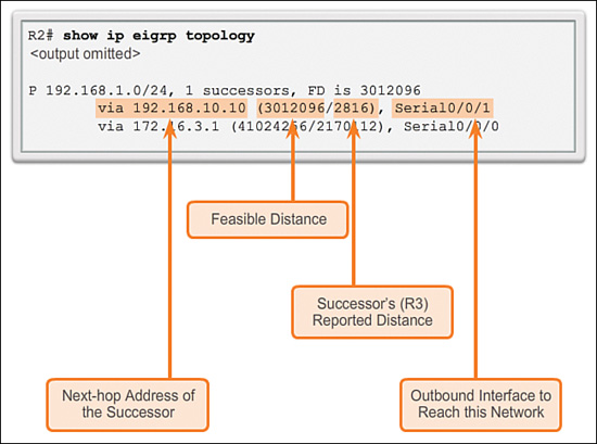
As shown in Figure 7-37, the second subentry shows the FS, R1 (if there is not a second entry, there are no FSs):
![]() via 172.16.3.1: Next-hop address of the FS, R1.
via 172.16.3.1: Next-hop address of the FS, R1.
![]() 41024256: R2’s new FD to 192.168.1.0/24, if R1 became the new successor and would be the new metric displayed in the IP routing table.
41024256: R2’s new FD to 192.168.1.0/24, if R1 became the new successor and would be the new metric displayed in the IP routing table.
![]() 2170112: RD of the FS, or R1’s metric to reach this network. The RD must be less than the current FD of 3,012,096 to meet the FC.
2170112: RD of the FS, or R1’s metric to reach this network. The RD must be less than the current FD of 3,012,096 to meet the FC.
![]() Serial 0/0/0: This is the outbound interface used to reach FS, if this router becomes the successor.
Serial 0/0/0: This is the outbound interface used to reach FS, if this router becomes the successor.

Topology Table: No Feasible Successor (7.3.3.7)
To see how DUAL uses successors and FSs, examine the routing table of R1, assuming that the network is converged.
Figure 7-38 displays a partial output from the show ip route command on R1.

The route to 192.168.1.0/24 shows that the successor is R3 through 192.168.10.6 with an FD of 2,170,112.
The IP routing table only includes the best path, the successor. To see whether there are any FSs, we must examine the EIGRP topology table. The topology table in Figure 7-39 only shows the successor 192.168.10.6, which is R3. There are no FSs.

By looking at the actual physical topology or network diagram, it is obvious that there is a backup route to 192.168.1.0/24 through R2. R2 is not an FS because it does not meet the FC. Although the topology clearly shows that R2 is a backup route, EIGRP does not have a map of the network topology. EIGRP is a distance vector routing protocol and only knows about remote network information through its neighbors.
DUAL does not store the route through R2 in the topology table. All links can be displayed using the show ip eigrp topology all-links command. This command displays links whether they satisfy the FC or not.
As shown in Figure 7-40, the show ip eigrp topology all-links command shows all possible paths to a network, including successors, FSs, and even those routes that are not FSs.

R1’s FD to 192.168.1.0/24 is 2,170,112 through the successor R3. For R2 to be considered an FS, it must meet the FC. R2’s RD to R1 to reach 192.168.1.0/24 must be less than the R1’s current FD. Per the figure, R2’s RD is 3,012,096, which is higher than R1’s current FD of 2,170,112.
Even though R2 looks like a viable backup path to 192.168.1.0/24, R1 has no idea that the path is not a potential loop back through itself. EIGRP is a distance vector routing protocol, without the ability to see a complete, loop-free topological map of the network. DUAL’s method of guaranteeing that a neighbor has a loop-free path is that the neighbor’s metric must satisfy the FC. By ensuring that the RD of the neighbor is less than its own FD, the router can assume that this neighboring router is not part of its own advertised route, thus always avoiding the potential for a loop.
R2 can be used as a successor if R3 fails; however, there is a longer delay before adding it to the routing table. Before R2 can be used as a successor, DUAL must do further processing.
![]() Activity 7.3.3.8: Determine the Feasible Successor
Activity 7.3.3.8: Determine the Feasible Successor
Go to the course online to perform this practice activity.
DUAL and Convergence (7.3.4)
DUAL is responsible for maintaining the EIGRP topology table and installing routes in the routing table.
DUAL Finite State Machine (FSM) (7.3.4.1)
The centerpiece of EIGRP is DUAL and its EIGRP route-calculation engine. The actual name of this technology is DUAL Finite State Machine (FSM). This FSM contains all the logic used to calculate and compare routes in an EIGRP network. Figure 7-41 shows a simplified version of the DUAL FSM.

An FSM is an abstract machine, not a mechanical device with moving parts. FSMs define a set of possible states that something can go through, what events cause those states, and what events result from those states. Designers use FSMs to describe how a device, computer program, or routing algorithm reacts to a set of input events.
FSMs are beyond the scope of this course. However, the concept is used to examine some of the output from EIGRP’s FSM using the debug eigrp fsm command. Use this command to examine what DUAL does when a route is removed from the routing table.
DUAL: Feasible Successor (7.3.4.2)
R2 is currently using R3 as the successor to 192.168.1.0/24. In addition, R2 currently lists R1 as an FS, as shown in Figure 7-42. Currently, all links are operational. The red X in the figure indicates a link failure to be simulated later.

The show ip eigrp topology output for R2 in Figure 7-43 verifies that R3 is the successor and R1 is the FS for the 192.168.1.0/24 network.

To understand how DUAL can use an FS when the path using the successor is no longer available, a link failure is simulated between R2 and R3. Before simulating the failure, DUAL debugging must be enabled using the debug eigrp fsm command on R2, as shown in Example 7-16.
Example 7-16 Debugging EIGRP Finite State Machine on R2
R2# debug eigrp fsm
EIGRP Finite State Machine debugging is on
R2# conf t
Enter configuration commands, one per line. End with CNTL/Z.
R2(config)# interface s 0/0/1
R2(config-if)# shutdown
<Output omitted>
EIGRP-IPv4(1):Find FS for dest 192.168.1.0/24. FD is 3012096, RD is 3012096 on tid 0
DUAL: AS(1) Removing dest 172.16.1.0/24, nexthop 192.168.10.10
DUAL: AS(1) RT installed 172.16.1.0/24 via 172.16.3.1
<Output omitted>
R2(config-if)# end
R2# undebug all
A link failure is simulated using the shutdown command on the Serial 0/0/1 interface on R2. The debug output displays the activity generated by DUAL when a link goes down. R2 must inform all EIGRP neighbors of the lost link, as well as update its own routing and topology tables. This example only shows selected debug output. In particular, notice that the DUAL FSM searches for and finds an FS for the route in the EIGRP topology table.
The FS R1 now becomes the successor and is installed in the routing table as the new best path to 192.168.1.0/24, as shown in Figure 7-44.

With an FS, this change in the routing table happens almost immediately.
As shown in Figure 7-45, the topology table for R2 now shows R1 as the successor and there are no new FSs.

If the link between R2 and R3 is made active again, R3 returns as the successor and R1 once again becomes the FS.
DUAL: No Feasible Successor (7.3.4.3)
Occasionally, the path to the successor fails and there are no FSs. In this instance, DUAL does not have a guaranteed loop-free backup path to the network, so the path is not in the topology table as an FS. If there are no FSs in the topology table, DUAL puts the network into the active state. DUAL actively queries its neighbors for a new successor.
R1 is currently using R3 as the successor to 192.168.1.0/24, as shown in Figure 7-46.

However, R1 does not have R2 listed as an FS, because R2 does not satisfy the FC. To understand how DUAL searches for a new successor when there is no FS, a link failure is simulated between R1 and R3.
Before the link failure is simulated, DUAL debugging is enabled with the debug eigrp fsm command on R1, as shown in Example 7-17.
Example 7-17 Debugging EIGRP Finite State Machine on R1
R1# debug eigrp fsm
EIGRP Finite State Machine debugging is on
R1# conf t
Enter configuration commands, one per line. End with CNTL/Z.
R1(config)# interface s 0/0/1
R1(config-if)# shutdown
<Output omitted>
EIGRP-IPv4(1): Find FS for dest 192.168.1.0/24. FD is 2170112, RD is 2170112
DUAL: AS(1) Dest 192.168.1.0/24 entering active state for tid 0.
EIGRP-IPv4(1): dest(192.168.1.0/24) active
EIGRP-IPv4(1): rcvreply: 192.168.1.0/24 via 172.16.3.2 metric 41024256/3012096
EIGRP-IPv4(1): reply count is 1
EIGRP-IPv4(1): Find FS for dest 192.168.1.0/24. FD is 72057594037927935, RD is
72057594037927935
DUAL: AS(1) Removing dest 192.168.1.0/24, nexthop 192.168.10.6
DUAL: AS(1) RT installed 192.168.1.0/24 via 172.16.3.2
<Output omitted>
R1(config-if)# end
R1# undebug all
A link failure is simulated using the shutdown command on the Serial 0/0/1 interface on R1.
When the successor is no longer available and there is no feasible successor, DUAL puts the route into an active state. DUAL sends EIGRP queries, asking other routers for a path to the network. Other routers return EIGRP replies, letting the sender of the EIGRP query know whether they have a path to the requested network. If none of the EIGRP replies have a path to this network, the sender of the query does not have a route to this network.
The highlighted debug output in Example 7-17 shows the 192.168.1.0/24 network put into the active state and EIGRP queries sent to other neighbors. R2 replies with a path to this network, which becomes the new successor and is installed into the routing table.
If the sender of the EIGRP queries receives EIGRP replies that include a path to the requested network, the preferred path is added as the new successor and added to the routing table. This process takes longer than if DUAL had an FS in its topology table and was able to quickly add the new route to the routing table. In Figure 7-47, notice that R1 has a new route to the 192.168.1.0/24 network. The new EIGRP successor is Router R2.

Figure 7-48 shows that the topology table for R1 now has R2 as the successor with no new FSs.

If the link between R1 and R3 is made active again, R3 returns as the successor. However, R2 is still not the FS, because it does not meet the FC.
Packet Tracer Activity 7.3.4.4: Investigating DUAL FSM
In this activity, you will modify the EIGRP metric formula to cause a change in the topology. This allows you to see how EIGRP reacts when a neighbor goes down because of unforeseen circumstances. You will then use the debug command to view topology changes and see how the DUAL Finite State Machine determines successor and feasible successor paths to reconverge the network.
Configuring EIGRP for IPv6 (7.4)
This section compares EIGRP for IPv4 and IPv6 as well as discusses EIGRP for IPv6 configuration and verification.
EIGRP for IPv4 Versus IPv6 (7.4.1)
EIGRP for IPv6 is very similar to EIGRP for IPv4, although IPv6 requires some unique considerations.
EIGRP for IPv6 (7.4.1.1)
Similar to its IPv4 counterpart, EIGRP for IPv6 exchanges routing information to populate the IPv6 routing table with remote prefixes. EIGRP for IPv6 was made available in Cisco IOS Release 12.4(6)T.
In IPv6, the network address is referred to as the prefix and the subnet mask is called the prefix length.
EIGRP for IPv4 runs over the IPv4 network layer, communicating with other EIGRP IPv4 peers, and advertising only IPv4 routes. EIGRP for IPv6 has the same functionality as EIGRP for IPv4 but uses IPv6 as the network layer transport, communicating with EIGRP for IPv6 peers and advertising IPv6 routes.
EIGRP for IPv6 also uses DUAL as the computation engine to guarantee loop-free paths and backup paths throughout the routing domain.
As with all IPv6 routing protocols, EIGRP for IPv6 has separate processes from its IPv4 counterpart. The processes and operations are basically the same as in the IPv4 routing protocol; however, they run independently. EIGRP for IPv4 and EIGRP for IPv6 each have separate EIGRP neighbor tables, EIGRP topology tables, and IP routing tables, as shown in Figure 7-49. EIGRP for IPv6 is a separate protocol-dependent module (PDM).

The EIGRP for IPv6 configuration and verification commands are very similar to those used in EIGRP for IPv4. These commands are described later in this section.
Comparing EIGRP for IPv4 and IPv6 (7.4.1.2)
Table 7-5 displays a quick comparison of EIGRP for IPv4 and EIGRP for IPv6.
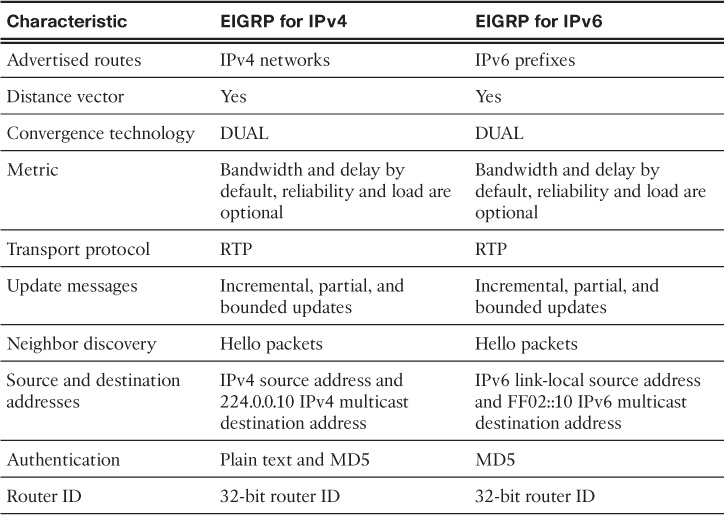
The following is a detailed explanation of the similarities and differences in the main features of EIGRP for IPv4 and EIGRP for IPv6:
![]() Advertised routes: EIGRP for IPv4 advertises IPv4 networks. EIGRP for IPv6 advertises IPv6 prefixes.
Advertised routes: EIGRP for IPv4 advertises IPv4 networks. EIGRP for IPv6 advertises IPv6 prefixes.
![]() Distance vector: Both EIGRP for IPv4 and IPv6 are advanced distance vector routing protocols. Both protocols use the same administrative distances.
Distance vector: Both EIGRP for IPv4 and IPv6 are advanced distance vector routing protocols. Both protocols use the same administrative distances.
![]() Convergence technology: EIGRP for IPv4 and IPv6 both use the DUAL algorithm. Both protocols use the same DUAL techniques and processes, including successor, FS, FD, and RD.
Convergence technology: EIGRP for IPv4 and IPv6 both use the DUAL algorithm. Both protocols use the same DUAL techniques and processes, including successor, FS, FD, and RD.
![]() Metric: Both EIGRP for IPv4 and IPv6 use bandwidth, delay, reliability, and load for their composite metric. Both routing protocols use the same composite metric and use only bandwidth and delay, by default.
Metric: Both EIGRP for IPv4 and IPv6 use bandwidth, delay, reliability, and load for their composite metric. Both routing protocols use the same composite metric and use only bandwidth and delay, by default.
![]() Transport protocol: The Reliable Transport Protocol (RTP) is responsible for guaranteed delivery of EIGRP packets to all neighbors for both protocols, EIGRP for IPv4 and IPv6.
Transport protocol: The Reliable Transport Protocol (RTP) is responsible for guaranteed delivery of EIGRP packets to all neighbors for both protocols, EIGRP for IPv4 and IPv6.
![]() Update messages: Both EIGRP for IPv4 and IPv6 send incremental updates when the state of a destination changes. The terms partial and bounded are used when referring to updates for both protocols.
Update messages: Both EIGRP for IPv4 and IPv6 send incremental updates when the state of a destination changes. The terms partial and bounded are used when referring to updates for both protocols.
![]() Neighbor discovery mechanism: EIGRP for IPv4 and EIGRP for IPv6 use a simple Hello mechanism to learn about neighboring routers and form adjacencies.
Neighbor discovery mechanism: EIGRP for IPv4 and EIGRP for IPv6 use a simple Hello mechanism to learn about neighboring routers and form adjacencies.
![]() Source and destination addresses: EIGRP for IPv4 sends messages to the multicast address 224.0.0.10. These messages use the source IPv4 address of the outbound interface. EIGRP for IPv6 sends its messages to the multicast address FF02::A. EIGRP for IPv6 messages are sourced using the IPv6 link-local address of the exit interface.
Source and destination addresses: EIGRP for IPv4 sends messages to the multicast address 224.0.0.10. These messages use the source IPv4 address of the outbound interface. EIGRP for IPv6 sends its messages to the multicast address FF02::A. EIGRP for IPv6 messages are sourced using the IPv6 link-local address of the exit interface.
![]() Authentication: EIGRP for IPv4 can use either plain text authentication or Message Digest 5 (MD5) authentication. EIGRP for IPv6 uses MD5.
Authentication: EIGRP for IPv4 can use either plain text authentication or Message Digest 5 (MD5) authentication. EIGRP for IPv6 uses MD5.
![]() Router ID: Both EIGRP for IPv4 and EIGRP for IPv6 use a 32-bit number for the EIGRP router ID. The 32-bit router ID is represented in dotted-decimal notation and is commonly referred to as an IPv4 address. If the EIGRP for IPv6 router has not been configured with an IPv4 address, the eigrp router-id command must be used to configure a 32-bit router ID. The process for determining the router ID is the same for both EIGRP for IPv4 and IPv6.
Router ID: Both EIGRP for IPv4 and EIGRP for IPv6 use a 32-bit number for the EIGRP router ID. The 32-bit router ID is represented in dotted-decimal notation and is commonly referred to as an IPv4 address. If the EIGRP for IPv6 router has not been configured with an IPv4 address, the eigrp router-id command must be used to configure a 32-bit router ID. The process for determining the router ID is the same for both EIGRP for IPv4 and IPv6.
IPv6 Link-Local Addresses (7.4.1.3)
Routers running a dynamic routing protocol such as EIGRP exchange messages between neighbors on the same subnet or link. Routers only need to send and receive routing protocol messages with their directly connected neighbors. These messages are always sent from the source IP address of the router that is doing the forwarding.
IPv6 link-local addresses are ideal for this purpose. An IPv6 link-local address enables a device to communicate with other IPv6-enabled devices on the same link and only on that link (subnet). Packets with a source or destination link-local address cannot be routed beyond the link from where the packet originated.
EIGRP for IPv6 messages are sent using
![]() Source IPv6 address: This is the IPv6 link-local address of the exit interface.
Source IPv6 address: This is the IPv6 link-local address of the exit interface.
![]() Destination IPv6 address: When the packet needs to be sent to a multicast address, it is sent to the IPv6 multicast address FF02::A, the all-EIGRP-routers with link-local scope. If the packet can be sent as a unicast address, it is sent to the link-local address of the neighboring router.
Destination IPv6 address: When the packet needs to be sent to a multicast address, it is sent to the IPv6 multicast address FF02::A, the all-EIGRP-routers with link-local scope. If the packet can be sent as a unicast address, it is sent to the link-local address of the neighboring router.
IPv6 link-local addresses are in the FE80::/10 range. The /10 indicates that the first 10 bits are 1111 1110 10xx xxxx, which results in the first hextet having a range of 1111 1110 1000 0000 (FE80) to 1111 1110 1011 1111 (FEBF).
![]() Activity 7.4.1.4: Compare EIGRPv4 and EIGRPv6
Activity 7.4.1.4: Compare EIGRPv4 and EIGRPv6
Go to the course online to perform this practice activity.
Configuring EIGRP for IPv6 (7.4.2)
This topic discusses the commands unique to configuring EIGRP for IPv6.
EIGRP for IPv6 Network Topology (7.4.2.1)
Figure 7-50 shows the network topology that is used for configuring EIGRP for IPv6.
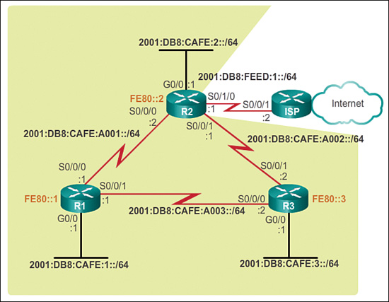
If the network is running dual-stack, using both IPv4 and IPv6 on all devices, EIGRP for both IPv4 and IPv6 can be configured on all the routers. However, in this section, the focus is solely on EIGRP for IPv6.
Only the IPv6 global unicast addresses have been configured on each router.
Example 7-18 displays the starting interface configurations on each router.
Example 7-18 IPv6 Interface Configurations
R1# show running-config
<Output omitted>
!
interface GigabitEthernet0/0
ipv6 address 2001:DB8:CAFE:1::1/64
!
interface Serial0/0/0
ipv6 address 2001:DB8:CAFE:A001::1/64
clock rate 64000
!
interface Serial0/0/1
ipv6 address 2001:DB8:CAFE:A003::1/64![]()
R2# show running-config
<Output omitted>
!
interface GigabitEthernet0/0
ipv6 address 2001:DB8:CAFE:2::1/64
!
interface Serial0/0/0
ipv6 address 2001:DB8:CAFE:A001::2/64
!
interface Serial0/0/1
ipv6 address 2001:DB8:CAFE:A002::1/64
clock rate 64000
!
interface Serial0/1/0
ipv6 address 2001:DB8:FEED:1::1/64![]()
R3# show running-config
<Output omitted>
!
interface GigabitEthernet0/0
ipv6 address 2001:DB8:CAFE:3::1/64
!
interface Serial0/0/0
ipv6 address 2001:DB8:CAFE:A003::2/64
clock rate 64000
!
interface Serial0/0/1
ipv6 address 2001:DB8:CAFE:A002::2/64
Notice the interface bandwidth values from the previous EIGRP for IPv4 configuration. Because EIGRP for IPv4 and IPv6 use the same metrics, modifying the bandwidth parameters influences both routing protocols.
Configuring IPv6 Link-Local Addresses (7.4.2.2)
Link-local addresses are automatically created when an IPv6 global unicast address is assigned to the interface. Global unicast addresses are not required on an interface; however, IPv6 link-local addresses are.
Unless configured manually, Cisco routers create the link-local address using the FE80::/10 prefix and the EUI-64 process. EUI-64 involves using the 48-bit Ethernet MAC address, inserting FFFE in the middle and flipping the seventh bit. For serial interfaces, Cisco uses the MAC address of an Ethernet interface. A router with several serial interfaces can assign the same link-local address to each IPv6 interface, because link-local addresses only need to be local on the link.
Link-local addresses created using the EUI-64 format, or in some cases random interface IDs, make it difficult to recognize and remember those addresses. Because IPv6 routing protocols use IPv6 link-local addresses for unicast addressing and next-hop address information in the routing table, it is common practice to make it an easily recognizable address. Configuring the link-local address manually provides the ability to create an address that is recognizable and easier to remember.
Link-local addresses can be configured manually using the same interface configuration mode command used to create IPv6 global unicast addresses, but with different parameters:
Router(config-if)# ipv6 address link-local-address link-local
A link-local address has a prefix within the range of FE80 to FEBF. When an address begins with this hextet (16-bit segment), the link-local keyword must follow the address.
Example 7-19 shows the configuration of a link-local address using the ipv6 address interface configuration mode command.
Example 7-19 Configuring Link-Local Addresses on R1
R1(config)# interface s 0/0/0
R1(config-if)# ipv6 address fe80::1 ?
link-local Use link-local address
R1(config-if)# ipv6 address fe80::1 link-local
R1(config-if)# exit
R1(config)# interface s 0/0/1
R1(config-if)# ipv6 address fe80::1 link-local
R1(config-if)# exit
R1(config)# interface g 0/0
R1(config-if)# ipv6 address fe80::1 link-local
R1(config-if)#
The link-local address FE80::1 is used to make it easily recognizable as belonging to router R1. The same IPv6 link-local address is configured on all of R1’s interfaces. FE80::1 can be configured on each link because it only has to be unique on that link. The configurations for R2 and R3 are similar to R1.
As shown in Figure 7-51, the show ipv6 interface brief command is used to verify the IPv6 link-local and global unicast addresses on all interfaces.

Configuring the EIGRP for IPv6 Routing Process (7.4.2.3)
The ipv6 unicast-routing global configuration mode command enables IPv6 routing on the router. This command is required before any IPv6 routing protocol can be configured. This command is not required to configure IPv6 addresses on the interfaces, but it is necessary for the router to be enabled as an IPv6 router.
EIGRP for IPv6
The following global configuration mode command is used to enter router configuration mode for EIGRP for IPv6:
Router(config)# ipv6 router eigrp autonomous-system
Similar to EIGRP for IPv4, the autonomous-system value must be the same on all routers in the routing domain, as shown in Example 7-20.
Example 7-20 Configuring the EIGRP for IPv6 Routing Process
#R1(config)# ipv6 router eigrp 2
% IPv6 routing not enabled
R1(config)# ipv6 unicast-routing
R1(config)# ipv6 router eigrp 2
R1(config-rtr)# eigrp router-id 1.0.0.0
R1(config-rtr)# no shutdown![]()
R2(config)# ipv6 unicast-routing
R2(config)# ipv6 router eigrp 2
R2(config-rtr)# eigrp router-id 2.0.0.0
R2(config-rtr)# no shutdown
R2(config-rtr)#![]()
R3(config)# ipv6 unicast-routing
R3(config)# ipv6 router eigrp 2
R3(config-rtr)# eigrp router-id 3.0.0.0
R3(config-rtr)# no shutdown
R3(config-rtr)#
Notice in the example that the EIGRP for IPv6 routing process could not be configured until IPv6 routing was enabled with the ipv6 unicast-routing global configuration mode command.
Router ID
The eigrp router-id command is used to configure the router ID. EIGRP for IPv6 uses a 32-bit value for the router ID. To obtain that value, EIGRP for IPv6 uses the same process as EIGRP for IPv4. The eigrp router-id command takes precedence over any loopback or physical interface IPv4 addresses. If an EIGRP for IPv6 router does not have any active interfaces with an IPv4 address, the eigrp router-id command is required.
The router ID should be a unique 32-bit number in the EIGRP for IP routing domain; otherwise, routing inconsistencies can occur.
The eigrp router-id command is used to configure the router ID for EIGRP. Some versions of IOS will accept the command router-id, without first specifying eigrp. The running config, however, will display eigrp router-id, regardless of which command is used.
By default, the EIGRP for IPv6 process is in a shutdown state. The no shutdown command is required to activate the EIGRP for IPv6 process, as shown in Example 7-20. This command is not required for EIGRP for IPv4. Although EIGRP for IPv6 is enabled, neighbor adjacencies and routing updates cannot be sent and received until EIGRP is activated on the appropriate interfaces.
Both the no shutdown command and a router ID are required for the router to form neighbor adjacencies.
The ipv6 eigrp Interface Command (7.4.2.4)
EIGRP for IPv6 uses a different method to enable an interface for EIGRP. Instead of using the network router configuration mode command to specify matching interface addresses, EIGRP for IPv6 is configured directly on the interface.
Use the following interface configuration mode command to enable EIGRP for IPv6 on an interface:
Router(config-if)# ipv6 eigrp autonomous-system
The autonomous-system value must be the same as the autonomous system number used to enable the EIGRP routing process. Similar to the network command used in EIGRP for IPv4, the ipv6 eigrp interface command
![]() Enables the interface to form adjacencies and send or receive EIGRP for IPv6 updates
Enables the interface to form adjacencies and send or receive EIGRP for IPv6 updates
![]() Includes the prefix (network) of this interface in EIGRP for IPv6 routing updates
Includes the prefix (network) of this interface in EIGRP for IPv6 routing updates
Example 7-21 shows the configuration to enable EIGRP for IPv6 on the interfaces for all three routers.
Example 7-21 Enabling EIGRP for IPv6 on the Interfaces
R1(config)# interface g0/0
R1(config-if)# ipv6 eigrp 2
R1(config-if)# exit
R1(config)# interface s 0/0/0
R1(config-if)# ipv6 eigrp 2
R1(config-if)# exit
R1(config)# interface s 0/0/1
R1(config-if)# ipv6 eigrp 2
R1(config-if)#![]()
R2(config)# interface g 0/0
R2(config-if)# ipv6 eigrp 2
R2(config-if)# exit
R2(config)# interface s 0/0/0
R2(config-if)# ipv6 eigrp 2
R2(config-if)# exit
%DUAL-5-NBRCHANGE: EIGRP-IPv6 2: Neighbor FE80::1 (Serial0/0/0) is up: new adjacency
R2(config)# interface s 0/0/1
R2(config-if)# ipv6 eigrp 2
R2(config-if)#![]()
R3(config)# interface g 0/0
R3(config-if)# ipv6 eigrp 2
R3(config-if)# exit
R3(config)# interface s 0/0/0
R3(config-if)# ipv6 eigrp 2
R3(config-if)#
*Mar 4 03:02:00.696: %DUAL-5-NBRCHANGE: EIGRP-IPv6 2: Neighbor FE80::1
(Serial0/0/0) is up: new adjacency
R3(config-if)# exit
R3(config)# interface s 0/0/1
R3(config-if)# ipv6 eigrp 2
R3(config-if)#
*Mar 4 03:02:17.264: %DUAL-5-NBRCHANGE: EIGRP-IPv6 2: Neighbor FE80::2
(Serial0/0/1) is up: new adjacency
Notice the message following the serial 0/0/0 interface in R2:
%DUAL-5-NBRCHANGE: EIGRP-IPv6 2: Neighbor FE80::1 (Serial0/0/0) is up: new adjacency
This message indicates that R2 has now formed an EIGRP-IPv6 adjacency with the neighbor at link-local address FE80::1. Because static link-local addresses were configured on all three routers, it is easy to determine that this adjacency is with Router R1 (FE80::1).
Passive Interface with EIGRP for IPv6
The same passive-interface command used for IPv4 is used to configure an interface as passive with EIGRP for IPv6. As shown in Example 7-22, the show ipv6 protocols command is used to verify the configuration.
Example 7-22 Configuring and Verifying EIGRP for IPv6 Passive Interfaces
R1(config)# ipv6 router eigrp 2
R1(config-rtr)# passive-interface gigabitethernet 0/0
R1(config-rtr)# end
R1# show ipv6 protocols
IPv6 Routing Protocol is "eigrp 2"
EIGRP-IPv6 Protocol for AS(2)
<output omitted>
Interfaces:
Serial0/0/0
Serial0/0/1
GigabitEthernet0/0 (passive)
Redistribution:
None
R1#
Verifying EIGRP for IPv6 (7.4.3)
Verifying EIGRP for IPv6 is similar to verifying EIGRP for IPv4. The commands are almost identical. Simply replace the ip with ipv6.
Verifying EIGRP for IPv6: Examining Neighbors (7.4.3.1)
Similar to EIGRP for IPv4, before any EIGRP for IPv6 updates can be sent or received, routers must establish adjacencies with their neighbors.
Use the show ipv6 eigrp neighbors command to view the neighbor table and verify that EIGRP for IPv6 has established an adjacency with its neighbors. The output shown in Figure 7-52 displays the IPv6 link-local address of the adjacent neighbor and the interface that this router uses to reach that EIGRP neighbor.

Using meaningful link-local addresses makes it easy to recognize the neighbors R2 at FE80::2 and R3 at FE80::3.
The output from the show ipv6 eigrp neighbors command includes
![]() H column: Lists the neighbors in the order that they were learned.
H column: Lists the neighbors in the order that they were learned.
![]() Address: IPv6 link-local address of the neighbor.
Address: IPv6 link-local address of the neighbor.
![]() Interface: Local interface on which this Hello packet was received.
Interface: Local interface on which this Hello packet was received.
![]() Hold: Current hold time. When a Hello packet is received, this value is reset to the maximum hold time for that interface and then counts down to 0. If 0 is reached, the neighbor is considered down.
Hold: Current hold time. When a Hello packet is received, this value is reset to the maximum hold time for that interface and then counts down to 0. If 0 is reached, the neighbor is considered down.
![]() Uptime: Amount of time since this neighbor was added to the neighbor table.
Uptime: Amount of time since this neighbor was added to the neighbor table.
![]() SRTT and RTO: Used by RTP to manage reliable EIGRP packets.
SRTT and RTO: Used by RTP to manage reliable EIGRP packets.
![]() Queue Count: Should always be 0. If it is more than 0, EIGRP packets are waiting to be sent.
Queue Count: Should always be 0. If it is more than 0, EIGRP packets are waiting to be sent.
![]() Sequence Number: Used to track updates, queries, and reply packets.
Sequence Number: Used to track updates, queries, and reply packets.
The show ipv6 eigrp neighbors command is useful for verifying and troubleshooting EIGRP for IPv6. If an expected neighbor is not listed, ensure that both ends of the link are up/up using the show ipv6 interface brief command. The same requirements exist for establishing neighbor adjacencies with EIGRP for IPv6 as they do for IPv4. If both sides of the link have active interfaces, check to see
![]() Are both routers configured with the same EIGRP autonomous system number?
Are both routers configured with the same EIGRP autonomous system number?
![]() Is the interface enabled for EIGRP for IPv6 with the correct autonomous system number?
Is the interface enabled for EIGRP for IPv6 with the correct autonomous system number?
Verifying EIGRP for IPv6: show ipv6 protocols Command (7.4.3.2)
The show ipv6 protocols command displays the parameters and other information about the state of any active IPv6 routing protocol processes currently configured on the router. The show ipv6 protocols command displays different types of output specific to each IPv6 routing protocol.
The output in Figure 7-53 is labeled for easy reference.
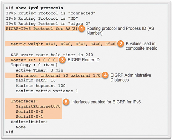
The labels in Figure 7-53 indicate several EIGRP for IPv6 parameters previously discussed, including
1. EIGRP for IPv6 is an active dynamic routing protocol on R1 configured with the autonomous system number 2.
2. These are the k values used to calculate the EIGRP composite metric. K1 and K3 are 1, by default, and K2, K4, and K5 are 0, by default.
3. The EIGRP for IPv6 router ID of R1 is 1.0.0.0.
4. Same as EIGRP for IPv4, EIGRP for IPv6 administrative distances have an internal AD of 90 and an external AD of 170 (default values).
5. The interfaces are enabled for EIGRP for IPv6.
The output from the show ipv6 protocols command is useful in debugging routing operations. The Interfaces section shows on which interfaces EIGRP for IPv6 has been enabled. This is useful in verifying that EIGRP is enabled on all the appropriate interfaces with the correct autonomous system number.
Verifying EIGRP for IPv6: Examine the IPv6 Routing Table (7.4.3.3)
As with any routing protocol, the goal is to populate the IP routing table with routes to remote networks and the best paths to reaching those networks. As with IPv4, it is important to examine the IPv6 routing table and determine whether it is populated with the correct routes.
The IPv6 routing table is examined using the show ipv6 route command. EIGRP for IPv6 routes are denoted in the routing table with a D, similar to its counterpart for IPv4.
Example 7-23 displays the EIGRP for IPv6 routes on all three routers.
Example 7-23 IPv6 EIGRP Routes
R1# show ipv6 route eigrp
<Output omitted>
D 2001:DB8:CAFE:2::/64 [90/3524096]
via FE80::3, Serial0/0/1
D 2001:DB8:CAFE:3::/64 [90/2170112]
via FE80::3, Serial0/0/1
D 2001:DB8:CAFE:A002::/64 [90/3523840]
via FE80::3, Serial0/0/1
R1#![]()
R2# show ipv6 route eigrp
<Output omitted>
D 2001:DB8:CAFE:1::/64 [90/3524096]
via FE80::3, Serial0/0/1
D 2001:DB8:CAFE:3::/64 [90/3012096]
via FE80::3, Serial0/0/1
D 2001:DB8:CAFE:A003::/64 [90/3523840]
via FE80::3, Serial0/0/1
R2#![]()
R3# show ipv6 route eigrp
<Output omitted>
D 2001:DB8:CAFE:1::/64 [90/2170112]
via FE80::1, Serial0/0/0
D 2001:DB8:CAFE:2::/64 [90/3012096]
via FE80::2, Serial0/0/1
D 2001:DB8:CAFE:A001::/64 [90/41024000]
via FE80::1, Serial0/0/0
via FE80::2, Serial0/0/1
R3#
The output in Example 7-23 shows that R1 has installed three EIGRP routes to remote IPv6 networks in its IPv6 routing table:
![]() 2001:DB8:CAFE:2::/64 through R3 (FE80::3) using its Serial 0/0/1 interface
2001:DB8:CAFE:2::/64 through R3 (FE80::3) using its Serial 0/0/1 interface
![]() 2001:DB8:CAFE:3::/64 through R3 (FE80::3) using its Serial 0/0/1 interface
2001:DB8:CAFE:3::/64 through R3 (FE80::3) using its Serial 0/0/1 interface
![]() 2001:DB8:CAFE:A002::/64 through R3 (FE80::3) using its Serial 0/0/1 interface
2001:DB8:CAFE:A002::/64 through R3 (FE80::3) using its Serial 0/0/1 interface
All three routes are using Router R3 as the next-hop router (successor). Notice that the routing table uses the link-local address as the next-hop address. Because each router has had all its interfaces configured with a unique and distinguishable link-local address, it is easy to recognize that the next-hop router through FE80::3 is Router R3. Also, notice that R3 has two equal-cost paths to 2001:DB8:CAFE:A001::/64. One path is through R1 at FE80::1, and the other path is through R2 at FE80::2.
Packet Tracer Activity 7.4.3.4: Configuring Basic EIGRP with IPv6
In this activity, you will configure the network with EIGRP routing for IPv6. You will also assign router IDs, configure passive interfaces, verify that the network is fully converged, and display routing information using show commands.
![]() EIGRP for IPv6 has the same overall operation and features as EIGRP for IPv4. There are a few major differences between them.
EIGRP for IPv6 has the same overall operation and features as EIGRP for IPv4. There are a few major differences between them.
![]() EIGRP for IPv6 is configured directly on the router interfaces.
EIGRP for IPv6 is configured directly on the router interfaces.
![]() With EIGRP for IPv6, a router ID is required on each router or the routing process does not start.
With EIGRP for IPv6, a router ID is required on each router or the routing process does not start.
![]() The EIGRP for IPv6 routing process uses a shutdown feature.
The EIGRP for IPv6 routing process uses a shutdown feature.
![]() Lab 7.4.3.5: Configuring Basic EIGRP for IPv6
Lab 7.4.3.5: Configuring Basic EIGRP for IPv6
In this lab, you will complete the following objectives:
![]() Part 1: Build the Network and Verify Connectivity
Part 1: Build the Network and Verify Connectivity
![]() Part 2: Configure EIGRP for IPv6 Routing
Part 2: Configure EIGRP for IPv6 Routing
![]() Part 3: Verify EIGRP for IPv6 Routing
Part 3: Verify EIGRP for IPv6 Routing
![]() Part 4: Configure and Verify Passive Interfaces
Part 4: Configure and Verify Passive Interfaces
Summary (7.5)
![]() Class Activity 7.5.1.1: Portfolio RIP and EIGRP
Class Activity 7.5.1.1: Portfolio RIP and EIGRP
You are preparing a portfolio file for comparison of RIP and EIGRP routing protocols.
Think of a network with three interconnected routers with each router providing a LAN for PCs, printers, and other end devices. The graphic on this page depicts one example of a topology like this.
In this modeling activity scenario, you will be creating, addressing, and configuring a topology, using verification commands, and comparing/contrasting RIP and EIGRP routing protocol outputs.
Complete the PDF reflection questions accompanying this activity. Save your work and be prepared to share your answers with the class. Also save a copy of your work for later use within this course or for portfolio reference.
EIGRP (Enhanced Interior Gateway Routing Protocol) is a classless, distance vector routing protocol. EIGRP is an enhancement of another Cisco routing protocol, IGRP (Interior Gateway Routing Protocol), which is now obsolete. EIGRP was initially released in 1992 as a Cisco-proprietary protocol available only on Cisco devices. In 2013, Cisco released a basic functionality of EIGRP as an open standard to the IETF.
EIGRP uses the source code of “D” for DUAL in the routing table. EIGRP has a default administrative distance of 90 for internal routes and 170 for routes imported from an external source, such as default routes.
EIGRP is an advanced distance vector routing protocol that includes features not found in other distance vector routing protocols like RIP. These features include Diffusing Update Algorithm (DUAL), establishing neighbor adjacencies, Reliable Transport Protocol (RTP), partial and bounded updates, and equal and unequal cost load balancing.
EIGRP uses PDMs (Protocol-Dependent Modules), giving it the capability to support different Layer 3 protocols, including IPv4 and IPv6. EIGRP uses RTP (Reliable Transport Protocol) as the transport layer protocol for the delivery of EIGRP packets. EIGRP uses reliable delivery for EIGRP updates, queries, and replies, and uses unreliable delivery for EIGRP Hellos and acknowledgments. Reliable RTP means that an EIGRP acknowledgment must be returned.
Before any EIGRP updates are sent, a router must first discover its neighbors. This is done with EIGRP Hello packets. The Hello and hold-down values do not need to match for two routers to become neighbors. The show ip eigrp neighbors command is used to view the neighbor table and verify that EIGRP has established an adjacency with its neighbors.
EIGRP does not send periodic updates like RIP. EIGRP sends partial or bounded updates, which include only the route changes and only to those routers that are affected by the change. The EIGRP composite metric uses bandwidth, delay, reliability, and load to determine the best path. By default, only bandwidth and delay are used.
At the center of EIGRP is DUAL (Diffusing Update Algorithm). The DUAL Finite State Machine is used to determine the best path and potential backup paths to every destination network. The successor is a neighboring router that is used to forward the packet using the least-cost route to the destination network. Feasible distance (FD) is the lowest calculated metric to reach the destination network through the successor. A feasible successor (FS) is a neighbor that has a loop-free backup path to the same network as the successor, and also meets the feasibility condition. The feasibility condition (FC) is met when a neighbor’s reported distance (RD) to a network is less than the local router’s feasible distance to the same destination network. The reported distance is simply an EIGRP neighbor’s feasible distance to the destination network.
EIGRP is configured with the router eigrp autonomous-system command. The autonomous-system value is actually a process ID and must be the same on all routers in the EIGRP routing domain. The network command is similar to that used with RIP. The network is the classful network address of the directly connected interfaces on the router. A wildcard mask is an optional parameter that can be used to include only specific interfaces.
Practice
The following activities provide practice with the topics introduced in this chapter. The Labs and Class Activities are available in the companion Scaling Networks Lab Manual (ISBN 978-1-58713-325-1). The Packet Tracer Activities PKA files are found in the online course.
![]() Class Activity 7.5.1.1: Portfolio RIP and EIGRP
Class Activity 7.5.1.1: Portfolio RIP and EIGRP
![]() Lab 7.4.3.5: Configuring Basic EIGRP for IPv6
Lab 7.4.3.5: Configuring Basic EIGRP for IPv6
![]() Packet Tracer Activity 7.3.4.4: Investigating DUAL FSM
Packet Tracer Activity 7.3.4.4: Investigating DUAL FSM
![]() Packet Tracer Activity 7.4.3.4: Configuring Basic EIGRP with IPv6
Packet Tracer Activity 7.4.3.4: Configuring Basic EIGRP with IPv6
Check Your Understanding Questions
Complete all the review questions listed to test your understanding of the topics and concepts in this chapter. The appendix “Answers to ‘Check Your Understanding’ Questions” lists the answers.
1. Which of the following protocols can be routed by EIGRP as a consequence of the PDM feature? (Choose two.)
A. RTP
B. UDP
C. IPv4
D. IPv6
E. TCP
2. Which IPv4 multicast address does an EIGRP-enabled router use to send query packets?
A. 224.0.0.5
B. 224.0.0.9
C. 224.0.0.12
D. 224.0.0.10
3. Which protocol number is used to indicate that an EIGRP packet is encapsulated in an IP packet?
A. 6
B. 17
C. 88
D. 89
4. In the router eigrp 100 command, what does the value 100 represent?
A. The router ID
B. The metric
C. The autonomous system number
D. The administrative distance
5. What address and wildcard mask can be used to enable EIGRP for only the subnet 192.168.100.192 255.255.255.192?
A. 192.168.100.192 0.0.0.7
B. 192.168.100.192 0.0.0.15
C. 192.168.100.192 0.0.0.63
D. 192.168.100.192 0.0.0.127
6. Refer to Example 7-24. A network administrator is verifying the EIGRP configuration. Which conclusion can be drawn?
Example 7-24 Command Output for Question 6
R1# show ip protocols
Routing Protocol is "eigrp 64515"
Outgoing update filter list for all interfaces is not set
Incoming update filter list for all interfaces is not set
Default networks flagged in outgoing updates
Default networks accepted from incoming updates
EIGRP metric weight K1=1, K2=0, K3=1, K4=0, K5=0
EIGRP maximum hopcount 100
EIGRP maximum metric variance 1
Redistributing: eigrp 64515
Automatic network summarization is not in effect
Maximum path: 4
Routing for Networks:
192.168.1.4/30
Routing Information Sources:
Gateway Distance Last Update
192.168.1.6 90 6284
Distance: internal 90 external 170
A. There are 90 internal networks and 170 external networks in the routing table.
B. Up to four paths to the same destination with different costs can be included in the routing table.
C. Subnetted networks are included in route updates.
D. Metric weight values have been changed from their default values.
7. Which of the following values are included by default in the calculation of an EIGRP metric? (Choose two.)
A. Hop count
B. Reliability
C. Bandwidth
D. Delay
E. Load
8. Which bandwidth value is used when calculating the EIGRP metric of a route?
A. The fastest bandwidth of all outgoing interfaces between the source and destination
B. The slowest bandwidth of all outgoing interfaces between the source and destination
C. The slowest bandwidth of all interfaces on the router
D. The fastest bandwidth of all interfaces on the router
9. Refer to Example 7-25. What does the value 2816 represent in the output display?
Example 7-25 Command Output for Question 9
R1# show ip eigrp topology
IP-EIGRP Topology Table for AS 64515
Codes: P - Passive, A - Active, U - Update, Q - Query, R - Reply,
r - Reply status
P 192.168.1.4/30, 1 successors, FD is 2169856
via Connected, Serial0/0/1
P 172.16.0.64/26, 1 successors, FD is 2170112
via 192.168.1.6 (2170112/2816), Serial0/0/1
R1#
B. Reported distance
C. Feasible distance
D. Administrative distance
10. Which of the following conditions occurring simultaneously will result in an EIGRP route going into the active state? (Choose two.)
A. The successor is down.
B. The network has been recalculated.
C. One neighbor has not met the feasibility condition.
D. The router is not sending queries.
E. There is no feasible successor.
11. What operational feature is different for EIGRP for IPv6 compared to EIGRP for IPv4?
A. Router ID configuration
B. Neighbor discovery mechanisms
C. The source and destination addresses used within the EIGRP messages
D. DUAL algorithm calculations
12. Which address will EIGRP for IPv6 use as the router ID?
A. The highest link-local address that is configured on any enabled interface
B. The highest IPv6 address that is configured on any enabled interface
C. The highest interface MAC address
D. The highest IPv4 address that is configured on an enabled interface
13. Which destination address is used by EIGRP for IPv6 messages?
A. The 32-bit router ID of the neighbor
B. The all-EIGRP-routers link-local multicast address
C. The IPv6 global unicast address of the neighbor
D. The unique local IPv6 address of the neighbor
14. Fill in the blank. What EIGRP packet type is described by the function?
The__________packet is used to distribute routing information.
The__________packet is used to form an EIGRP neighbor relationship.
The__________packet is used by an EIGRP router to request more information.
The__________packet is used in response to an EIGRP router searching for a network.
The__________packet is used to confirm reliable delivery of a packet
15. What are the default administrative distances for each of the following types of EIGRP route?
Internal__________
External__________
Summary__________