
Robotic sensing for assessing and monitoring civil infrastructures
H. Myung, H. Jeon and Y.-S. Bang, Korea Advanced Institute of Science and Technology (KAIST), Republic of Korea
Y. Wang, Georgia Institute of Technology, USA
Abstract:
This chapter discusses robotic sensing technologies for assessing and monitoring civil infrastructures. The chapter first reviews the use of robotic sensing techniques to monitor civil structures. Vision-based robotic sensing techniques that are used for structural crack detection and structural displacement monitoring are discussed in detail. Remote robotic sensing techniques for structural health monitoring (SHM) are discussed, including wireless sensing for SHM, wireless power transmission, and wireless sensor nodes based on microwave and lasers. Finally, vibration-based mobile wireless sensors including climbing robots for structural damage detection are overviewed. A case study for mobile sensor networks using climbing robots is introduced.
Key words
robotics; structured light (SL); remote sensing; mobile wireless sensors
15.1 Introduction
For several decades, various sensors and sensing systems have been developed to monitor the safety condition of structures. This chapter describes structural health monitoring (SHM) or inspection systems using robotic technologies. The field of robotics had been widely explored long before SHM technologies attracted significant attention. However, only in recent years have robotic prototypes developed to a level of maturity that makes them suitable for realistic application in SHM. This survey will include robotic systems equipped with various sensing technologies, such as optical sensors, laser sensors, mobile wireless sensors, etc. Details of some example systems are also provided in subsequent sections.
Thus far, robotic development for SHM has concentrated primarily on the inspection of structures rather than the continuous monitoring of structures. These robots have unique locomotion systems to provide mobility in the structures to be inspected, and are equipped with various sensors, such as vision cameras, lasers, radio frequency (RF), optical fibers, etc., to monitor and assess structural condition. Robots specialized for SHM application have only recently been developed, but their use is expected to largely increase in the near future.
Based on the literature, the locomotion mechanisms of SHM/inspection robots can be classified as follows:
1. Wheeled robots moving on horizontal surfaces: these include most common types of robots that use wheels for locomotion on relatively flat horizontal surfaces or guided rails. For example, Yu et al. (2007) proposed a mobile robot system for inspecting and measuring cracks in concrete structures. The safety of a subway inner wall is evaluated in this study. The mobile robot system was controlled to maintain a constant distance from walls while acquiring image data with a camera. There have not been many examples of wheeled locomotion, since this mechanism is not adequate for inspecting various structural elements other than the planar ground.
2. Wall-climbing/crawling robots: certain climbing and crawling mechanisms, some of which are bio-mimetic, have been developed for movement on vertical walls or uneven surfaces. Examples include gecko-like locomotion that can climb on smooth surfaces using directional adhesion, a vacuum-creating suction adhesion, and a climbing mechanism using adhesive materials. An article by M. Siegel deals with the status and prospects of remote and automated inspection methods for aircraft inspection (Siegel, 1997). Most of the methods use climbing and crawling devices. A climbing service robot for duct inspection and maintenance application in a nuclear reactor is another good example (Luk et al., 2001). Recently, a miniature crawler robot for structural inspection was introduced (Sheng et al., 2008). Their study dealt with the navigation of a miniature crawler robot performing an aircraft rivet inspection task. The authors used a vision-based localization algorithm and developed an efficient coverage path planning method. Teleoperated climbing inspection robots are often used, since they do not need complex navigation algorithms (Balaguer et al., 2000). Another type of robot for aerospace structures also used crawlers (Bar-Cohen and Backes, 2000). In addition, a bio-inspired miniature wall-climbing caterpillar robot has been developed by Zhang et al. (2010). A portable climbing robot used two legs that could adhere to a surface by suction cups (Bahr and Wu, 1994). As well as designing a wall-climbing robot, a control architecture based on fuzzy logic has been developed (Xiao, 2002; Xiao et al., 2004).
3. Snake-like robots: this type of robot is suitable for inspecting confined spaces and rough terrains that are hard to navigate, such as air ducts, pipes, and tubes too small for humans to enter. For example, Tokyo Tech’s Hirose-Fukushima Lab has developed some of the world’s most amazing mechanical snakes (Mori and Hirose, 2006; Guizzo, 2010).
4. Modular robots: by cascading multiple small modular robots, it is possible to build a robot capable of going through rough terrain and uneven surfaces. Self-reconfiguring modular robots have been developed, whereby multiple modules can automatically morph the configuration in arbitrary ways using small hooks for reconfigurable connection (Murata and Kurokawa, 2007). Recently, mobile sensor nodes have been developed by connecting two magnet-wheeled modules by a flexible beam (Lee et al., 2009; Zhu et al., 2010). This mobile sensing node can also attach an accelerometer to, or detach it from, the structural surface. Another example is a pair of wall-climbing robots with magnetic wheels (Fischer et al., 2007).
5. Aerial vehicles: robots in the form of quadrotors, helicopters, and airships can freely fly through and inspect structures. Quadrotors and miniature helicopters have been extensively tested. Most of the current prototypes have limited payload capacity and thus cannot carry many sensors (Pratt et al., 2008).
6. Underwater vehicles: submersible robots have been developed to inspect underwater structures. Several prototypes have been designed for inspecting oil storage tanks (Abdulla et al., 2010) and pipelines (Conte et al., 1996; Bodenmann et al., 2009).
Using a robot platform with an appropriate locomotion mechanism, different sensors can be incorporated for structural inspection purposes. Examples of these sensors, which can also be used in combination, are listed as follows:
1. Cameras: a camera is a useful sensor that can capture a lot of information, yet at the same time camera data are sensitive to illumination conditions (Lee and Shinozuka, 2006; Sheng et al., 2006). In order to achieve proper operation, it is important to calibrate the camera before use and compensate for noise and variations in illumination.
2. Optical scanners: the three-dimensional shape or motion of structures can be remotely reconstructed using optical scanners, although the cost of such scanners is usually high. Some low-cost solutions have recently been proposed and are still under development (Sergiyenko et al., 2009).
3. Fiber optics: fiber Bragg grating (FBG) sensors have been used for SHM. Some researchers have tried to use a PZT (lead zirconate titanate) transducer as a transmitter and an FBG as a receiver to detect impact andlor measure strain (Wild and Hinckley, 2007).
4. Combinations: a combination of different sensors carried by robots can provide more complete information about the structure. For example, a modular paired structured light (SL) system, which consists of lasers and a camera, was proposed to measure the 6-degrees of freedom (DOF) motion of large structures (Jeon et al., 2011a; Myung et al., 2011).
Besides using robots as sensor carriers, some research has also exploited robots for wirelessly delivering electrical power to SHM sensor nodes in close proximity. Inductive power transmission with RF signals (Huston et al., 2001), or optical delivery using power lasers can be used for this purpose (Park et al., 2010; Bang et al., 2011).
Robotic technologies have been utilized for inspecting/monitoring a large variety of structures. The following list provides a brief summary of different target structures for SHM or inspection robots.
1. Aircraft: since the aircraft surfaces to be inspected are not planar, several crawling or wall-climbing robots have been developed for aircraft inspection (Bar-Cohen and Backes, 2000). The researchers developed a multifunction automated crawling system (MACS) that offers an open architecture robotic platform for non-destructive evaluation (NDE) boards and sensors. MACS was designed to perform complex scanning tasks, taking advantage of its ability to easily turn or move forward and backward while attaching to a curved surface through suction cups.
2. Bridges and bridge cables: some robotic systems have been developed for bridge and bridge cable inspection. For steel bridge inspection, magnet-based locomotion has been explored (Mazumdar and Asada, 2010; Romero, 2010; Zhu, 2010). For cable inspection, wheel-based (Xu et al., 2008) or reconfigurable robots (Yuan et al., 2010) have been developed.
3. Power lines: power transmission lines have been inspected using cable climbing robots (Nayyerloo et al., 2009). The Hydro-Québec Research Institute in Canada unveiled their LineScout robot, which climbed on high-voltage power lines for inspection (Bouchard, 2010). Equipped with cameras, a thermo-infrared imager, and a smart navigation system, the LineScout robot can inspect line condition and determine locations in need of attention. In addition, a Tokyo-based company HiBot is working with the Kansai Electric Power Co. in Japan to deploy a new robot prototype in the field. Named Expliner, the robot can inspect several power cables simultaneously (Corley, 2009).
4. Pipelines, ducts, tubes, and sewages: narrow spaces that are not easily accessible for human beings can be inspected by a special robot with crawling mechanism. Robots for sewage inspection (Kirchner and Hertzberg, 1997; Adria et al., 2004), pipe cleaning and inspection (Li et al., 2009), and tube inspection (Kostin et al., 1999) have been developed.
15.2 Vision-based robotic sensing for structural health monitoring (SHM)
Due to the great advances in vision-based information processing technology, vision-based sensors or systems have been widely studied. Vision-based sensing is a highly important technique, particularly in robotics, and it is used for obstacle avoidance, mapping, and localization (Siegwart and Nourbakhsh, 2004). Also, in the field of civil engineering, much attention has been given to vision-based SHM, such as vision-based crack detection or vision-based structural displacement monitoring. In the following, various vision-based SHM systems and methods are introduced and their advantages and limitations are discussed.
15.2.1 Vision-based structural crack detection
Currently, to monitor structural conditions, inspectors periodically check visually for cracks on the structure, and the crack location is manually measured (Lim et al., 2011). Afterwards, structural safety is evaluated based on the number of cracks, their lengths and widths (Oh et al., 2009). As a result, the accuracy of the inspection may be lacking, and highly dependent on environmental conditions during the inspection and knowledge of the inspectors. Several research efforts related to a vision-based automated crack detection system using a mobile robot or a specially designed car (Tung et al., 2002; Yu et al., 2007; Oh et al., 2009; Lim et al., 2011) have been undertaken to address these problems. In most vision-based crack detection systems, a camera installed on the mobile robot or car captures images of the structure. Then various image processing techniques such as feature extraction and object recognition are used to detect cracks from the raw image. Since the size of the image is known from the geometry between the camera and the imaged object, the width and length of the crack can be calculated. Also, the location of the crack can be estimated using a localization system on the mobile robot.
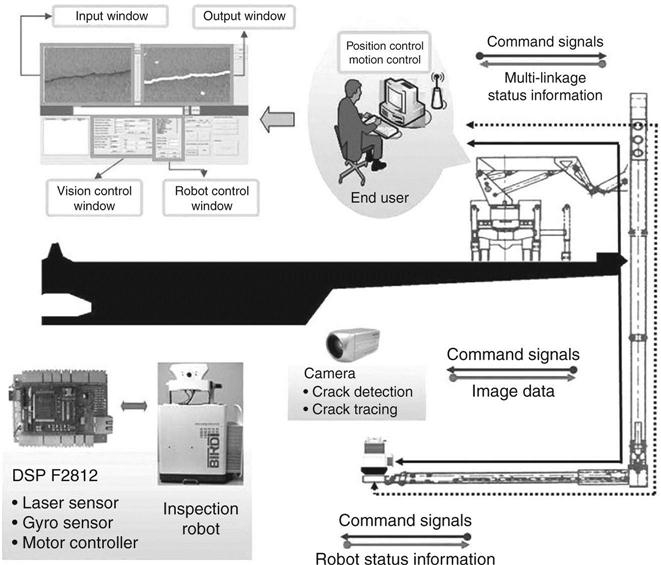
One example of vision-based crack detection systems applied to bridges is shown in Fig. 15.1. As shown in the figure, a specially designed car with a multi-linkage manipulator is used to monitor the condition of the bridge deck. By moving the multi-linkage manipulator, the entire structure can be monitored from a camera, which is mounted at the end of the manipulator. Although this system can detect cracks reliably, it is problematic when there is traffic, due to its large mass and low speed, or when the shape of the bridge is complex. Therefore, vision-based crack inspection systems with relatively small mobile robots have also been studied (Yu et al., 2007; Lim et al., 2011).
15.2.2 Vision-based structural displacement monitoring
Since most civil structures are subject to external loads such as traffic, earthquakes, and wind loads, it is important to monitor the structural behavior, especially the displacement, continuously. A number of studies have been performed on structural displacement monitoring methods or systems, and various sensors have been developed. Among the displacement measurement sensors or systems, vision-based displacement monitoring systems have gained great attention due to their low cost. Vision-based displacement monitoring systems most often use a high quality camera and artificial targets, or an SL, or laser range finder.
Since the 1960s, researchers have tried to use vision systems to directly measure structural displacement. Some approaches include the use of infrared lamp tracking systems (Marecos et al., 1969), laser beam pointing tracking systems (Isyumov et al., 1984), and transputer-based feature tracking systems (Stephen et al., 1993). Laser beams have been used at the Foyle Bridge (Leitch et al., 1989), where their images on target screens were tracked by a fixed camera. More recent examples have used specially manufactured optical devices to concurrently measure reference and target points using one image capturing device (Olaszek, 1999) or a high resolution camera system (Wahbeh et al., 2003), which required an expensive special purpose camera. Other researchers used a camera system with 30 × optical zooming capability installed far from the observation points at which artificial landmarks using light-emitting diodes (LEDs) are attached (Lee and Shinozuka, 2006). The problem with this approach is that it requires fixed observation points and precisely located landmarks. One current SHM system with vision sensors is installed on the Guangzhou New TV Tower, China, with a height of 610 m (Ni and Wong, 2009; Ni, 2009a). This system uses a high resolution camera with a telescopic lens having optical zooming capability observing markers at the target position. This system has some advantages, as it can directly measure displacement and its cost is relatively low. However, it can only measure 2D translational displacement and it is easily affected by external environmental conditions such as weather or illumination changes, due to the long distance between the target and the camera. For example, it cannot measure displacement in case of fog or obstructions in the line of sight (LoS). Another paper proposed a Kalman filtering scheme to fuse accelerometer signals with vision data for extracting 3D translation and rotation of a cubic target (Ni, 2009b). Others utilized a high resolution camera with a telescopic lens observing a cubic marker installed at the target position, which has the same limitations as before (Ni and Wong, 2009; Ni, 2009a).
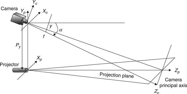
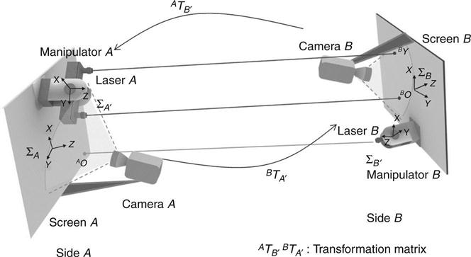
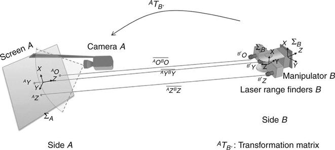
To mitigate those limitations, a novel vision-based displacement monitoring method has been introduced (Myung et al., 2011; Jeon et al., 2011a; Park et al., 2011b). To measure the three-dimensional translational and rotational displacements, and to make it robust to external environmental changes, Myung et al. developed a paired SL system. In a conventional SL approach, a simple pattern of beams is projected onto the target, and then depth and surface geometry are calculated from the image captured by a camera, as shown in Fig. 15.2 (Siegwart and Nourbakhsh, 2004). To precisely estimate long distance observations, a visually servoed paired (ViSP) SL system has been recently designed, as shown in Fig. 15.3 (Jeon et al., 2011a, b).The system is composed of two sides facing each other, each with a camera, one or two lasers, a screen, and a manipulator. Each laser projects its beams to the distant screen on the opposite side, and the camera near the screen captures the image of the screen. Due to the short distance between the screen and the camera, typically less than 20 cm, it is highly robust to environmental changes such as weather or illumination changes. A 2-DOF manipulator, which holds the lasers, controls the positions of the projected laser beams on the opposite side to be on the screen before it gets off the screen boundary. In this system, the relative 6-DOF displacement between the two sides can be calculated by using the positions of the three projected laser beams and the rotated angles of the manipulators.
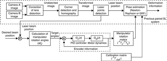
The entire process of the system operation is shown in Fig. 15.4. As shown in the figure, the camera on each side captures the image of the screen. Then, lens distortion is corrected. The boundary and the homography of the image are calculated from the undistorted image. After finding the boundary, the positions of the laser beams can be calculated from the known boundary size. The rotation angles of the 2-DOF manipulator are calculated from the current and desired positions of the laser beams. Afterwards, the manipulator rotation matrix is formed from encoder information taken from the motors for the proportional-integral-derivative (PID) controller. In this way, the 6-DOF displacement between two sides can be calculated by using the positions of the three laser beams and the manipulator rotation matrices.
The kinematics of the 6-DOF displacement defines the geometric relationship between the observed data m = ⌊AO, BO, AY⌋T, rotated angles of the manipulators, and estimated displacement p = [x,y,z,θ,φ,ψ]T.Here AO is the projected laser beam on the screen A and BO and BY are the projected laser beams on the screen B. The observed data can be calculated as follows:
[15.1]
 [15.1]
where, ATB and BTA are transformation matrices that transform the screen coordinates A and B, ATA, and BTB, are manipulator rotation matrices on sides A and B, respectively, L is the offset of a laser point from the center of a screen in the Y direction, and ZAB is the distance from screen A to screen B. The ATA can be represented as:
where θAene and ψAene are the rotated angles of the manipulator on side A about the X and Z axes, respectively. Since the laser beam is projected on the 2-DOF screen, the z component of the projected laser beams should be zero. By putting these three constraints together, the kinematic equation Mvs containing 6-DOF displacement p can be derived as follows (Jeon et al., 2011a):
[15.2]
The 6-DOF displacement p can be estimated by using the Newton-Raphson or EKF (extended Kalman filter) method (Moon and Stirling, 2000; Welch and Bishop, 2006; Jeon et al., 2011a).
Another approach to measuring the structural displacement in 6-DOF is to use 1-D laser range finders, as shown in Fig. 15.5. As the figure shows, at least three 1-D laser range finders project parallel beams onto the screen from the opposite side, and a camera near the screen captures the image of the screen. Unlike the previous SL-based system, not only the positions of the projected laser beams but also the distance measured from each laser range finder are used to calculate a relative 6-DOF displacement between the two sides. Since the laser range finders are installed only on one side and a single camera captures the image of the screen, the entire system is simpler than the previous system. However, the cost of the entire system is higher than SL systems, since the laser range finder with the data transmission function is more than five times more expensive on average than a 1-D laser projector.
15.3 Remote robotic sensing for SHM
15.3.1 Introduction to wireless sensing and wireless power transmission (WPT)
The RF or laser-based wireless sensing system is often used for remote monitoring of structural conditions. Wireless sensing nodes (WSN) can form a sensor network that assesses the condition of a structure. Eliminating the expensive cable installation, wireless sensing is considered to be a valuable method for the SHM of large structures. Nevertheless, large-scale field application of wireless sensing still faces many challenges. Even though designed to consume minimum energy, most WSNs operate with batteries that have limited life span. Therefore, the batteries should be monitored, replaced, or recharged regularly, requiring a significant amount of cost and labor for maintenance. To overcome these problems, WPT technology has been investigated to transmit energy to a remote receiver node for SHM. Power transmission is mainly achieved by either microwave or laser.
15.3.2 Wireless structural health monitoring
Since SHM of large civil infrastructures has gained great attention from recent collapses of bridges and buildings, wireless sensing technology is considered an important future sensing paradigm. Wireless sensors can constitute a network to share and gather measured data and to facilitate information aggregation for maintenance of a large structure.
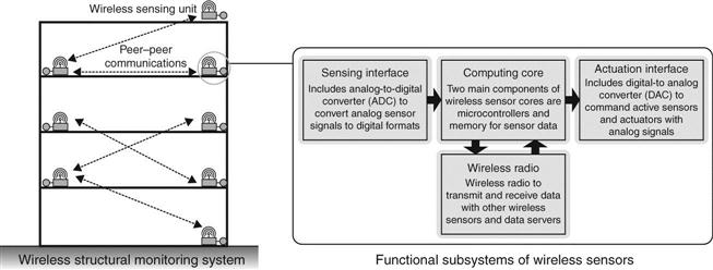
Performance of wireless sensors should be considered according to the purpose of SHM. Lynch (2005) introduced a wireless active sensing unit for SHM. As shown in Fig. 15.6, the wireless sensor system sends the measured data to the host after converting an analog sensor output to digital data via analog to digital converter (ADC). Some sensors, such as PZT, require an additional subsystem to excite the sensor. An impedance-based wireless sensor node was used to obtain the response of the PZT sensor (Mascarenas et al., 2007). A later version of the system was incorporated into a mobile robot system to expand the monitoring area using the robot’s mobility (Taylor et al., 2009). These wireless sensors used RF communication to send the response data to a base system. On the other hand, Park et al. (2011a) developed an optics-based wireless impedance measurement system, which transmits the response of the sensor through laser in continuous wave form, reducing computational load due to encoding sensor measurements.
15.3.3 Microwave-based WPT
Researchers have tried to develop a WPT system using microwave, because it has distinct advantages for distributing power through atmosphere and space, like broadcasting, toward multiple nodes. Several articles discuss the history of WPT using microwave (William, 1996; Matsumoto, 2002). Microwave-based WPT has been widely applied to operate many sensors installed around a site for SHM. Mascarenas et al. (2007) introduced a WPT system using 10 GHz X-band signals to supply power to the impedance sensing node. The performance of WPT at long distance was demonstrated with high power levels (Choi et al., 2004; Kim et al., 2006). However, doing so requires a large transmitter and receiver system. In the case of using WPT for SHM, the system size should be small and easy to install on a structure.
Autonomous robots can be used to access deployed sensors, transmit power, and collect the sensor information from a large WPT system. Todd et al. describes a sensor network paradigm using unmanned aerial vehicles (UAV) flown remotely or autonomously by a global positioning system (GPS)-based autopilot with RF communication system (Todd et al., 2007). The vehicle has onboard processing and storage systems to interrogate sensors, and gather and store data. The mobile robot system introduced above is also used as a WPT system for SHM that transmits energy to sensor nodes (Taylor et al., 2009). The WPT system as installed on the mobile robot communicates over 5.8 GHz to avoid interference with communication over the commonly used 2.4~2.5 GHz frequency. Experiments on sensing the acceleration of a bridge girder have been performed using WSNs operated by the WPT system. After approaching the wireless sensor node, the mobile robot begins to transmit power via the transmitter antenna. Received energy from the rectenna (receiver antenna) array installed on the mobile robot is stored in a capacitor for 40 s and used to operate a piezoelectric sensor for several seconds. Measured information is sent back to the mobile robot via RF.
In general, even though the transmitter antenna on the mobile robot is manually controlled to face the rectenna, the microwave-based WPT system needs careful design of the antennas and placement of the receiver sensors along with distributed beam forming of the microwave signal to increase efficiency.
15.3.4 Laser-based WPT
Compared to microwave, laser-based WPT has some advantages, such as reduced system size, collimated propagation, and no radio-frequency interference. The size of a given WPT system varies with the beam wavelength and its propagation characteristics. Laser wavelengths are significantly shorter than microwave, and the laser beam stays narrow over long distances. This means that the laser-based system can be more compact in size and lower in cost. In addition, interference with existing radio communication signals such as WiFi and cellular networks is avoided with the laser-based system. However, a significant limitation in laser-based WPT is that the laser and the receiver node should be at LoS to transmit power. In other words, the laser has to be directly aimed at the position of the receiver node.
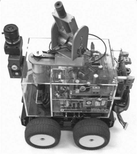
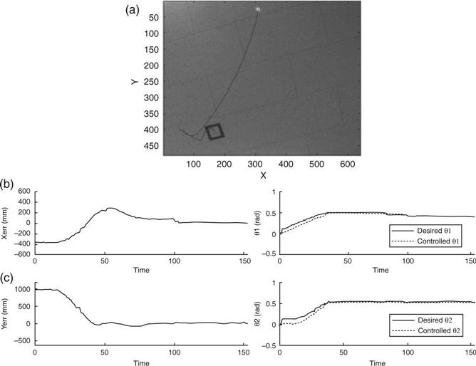
With the assumption that laser can be pointed to the desired position in advance, Park et al. (2010) developed a wireless sensing system for SHM that can provide a laser-based guided waveform to excite a PZT transducer. At the receiver node, the guided waveform can be measured with efficiency of 12.87% at up to 5 m distance. To obtain a higher efficiency, Ugur and Herbert (2006) developed a photovoltaic cavity converter system using Nd:YAG radiation for WPT, resulting in about 40% conversion efficiency. Laser flight testing with manual tracking of the laser indoors was demonstrated by Blackwell (2005). Laser-based WPT systems are restricted to motionless environments and manual operation. Although laser targeting can be done by a human operator over a short distance, it is difficult to control precisely. To resolve this problem, the laser targeting needs to be autonomously controlled by a robot system. Bang et al. (2011) introduced a mobile robot system that controls the robot’s manipulator for laser targeting using an image-based visual servoing (IBVS) technique, as shown in Fig. 15.7. They describe a robot system that can control the robot’s manipulator to project a laser to the receiver node position using visual information. The robot system consists of a camera, a laser, a 2-DOF manipulator, and a mobile platform. The camera is used to track positions of the projected laser points and the target object on a structure. Captured images are used to calculate the distance between the camera and the target. Laser targeting is done by controlling the manipulator. The velocity of the manipulator, ![]() , is related to the velocity of the image feature,
, is related to the velocity of the image feature, ![]() , by a total Jacobian, Jtot, as follows:
, by a total Jacobian, Jtot, as follows:
[15.3]
The total Jacobian is composed of the image Jacobian, Jimg, the transformation matrix, cTw, and the robot Jacobian, wJr, as follows:
[15.4]
The image Jacobian describes the relationship between the gradient of an image feature and the behavior of the corresponding object in a Cartesian space. The transformation matrix transforms the reference frame from the world frame to the camera frame. The robot Jacobian represents the kinematics of the robot’s manipulator. By defining an error function, containing the difference in the positions of the laser and the target, the desired velocity of the manipulator can be calculated using the pseudo inverse of the total Jacobian. A proportional control law is used to control the desired angles of the manipulator:
[15.5]
where Kp is the proportional gain of the controller.
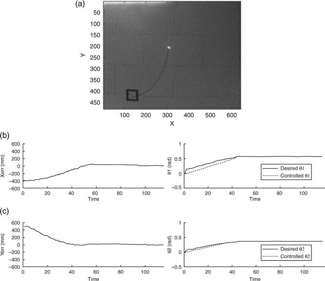
Relative position error will be continually reduced as the laser point approaches within the defined boundary around the target position. Figure 15.8 shows the result on a plane where the target is installed on the ceiling and in Fig. 15.9 with the ceiling tilted. Subfigure (a) in each figure shows the trajectory of the laser beam as controlled by the robot. Compared with the orthogonal ceiling, the performance on the tilted ceiling shows a bigger error near the target due to the error of the image Jacobian. However, the visual control law gives feedback information to the manipulator in order to eliminate position errors between the laser point and the target node. The experimental results validate that the proposed system has potential application to the laser-based WPT system.
15.4 Vibration-based mobile wireless sensors
Another recent advance in robotic sensing is to employ miniature robots as wireless sensor carriers that can autonomously navigate on a large structure. These robotic sensor carriers constitute a mobile sensor network. Each mobile sensing node can explore its surroundings and exchange information with its peers through wireless communication. The mobility of a sensing node has the potential to resolve some of the most critical challenges faced by static wireless sensor networks. For example, in order to provide enough information for updating the finite element model of a large-scale structure, measurement locations need to be as dense as possible. However, the cost of current high-precision wireless accelerometers is still prohibitive for dense deployment in practice. To resolve this difficulty, as illustrated in Fig. 15.10, a mobile sensor network offers flexible architectures. A relatively small number of mobile sensing nodes can provide adaptive and high spatial resolutions, while autonomously navigating through a large structure.
In addition, limited power supply is one of the largest constraints for wireless sensor networks (Churchill et al., 2003; Roundy, 2003; Sodano et al., 2004). This constraint can be alleviated by mobile sensor networks, if the mobile sensing nodes can periodically return to a base station for automatic recharging. Last but not least, for structural damage detection, mobile robots can be incorporated with functionality to excite a small section of the structure at a time, so that vibration signals can be obtained at a high signal-to-noise ratio. Compared with low-amplitude ambient vibrations that characterize structural global response, vibration signals caused by local excitation can provide more abundant information for component-level structural diagnosis. In the following, Section 15.4.1 provides a brief literature review on previous climbing robots and mobile sensor prototypes for civil structures. Section 15.4.2 showcases the performance of a recently developed magnet-wheeled mobile sensor for SHM.
15.4.1 Literature review on climbing robots and mobile sensors
Recent development in robotics has generated many prototypes that are capable of climbing in 3D environment. For example, the Robug IV prototype has eight legs and weighs 40 kg (Urwin-Wright et al., 2002). It uses pneumatic suction cups for adhesion and transports 5 kg of payload. Another prototype, Roma2, has two legs and also uses vacuum cups for 3D climbing (Balaguer et al., 2005). The Roma2 model has reduced kinematics and lighter weight (25 kg); it moves at a maximum speed of 2.5 cm/s during linear motion. Nevertheless, these robot prototypes are large and clumsy as mobile sensor carriers that need to move, for example, on a truss bridge.
Smaller robot prototypes have also been developed. Latest bio-mimetic research has led to the design of StickyBot, a wall-climbing robot prototype that was named by Time Magazine as one of the ‘Best Inventions in 2006’ (Kim et al., 2007). The StickyBot mimics gecko movement and can climb on smooth surfaces using directional adhesion. It weighs only 370 g and moves at a maximum speed of 4.0 cm/s. Waalbot, which uses elastomer adhesion, is another recent robot prototype that climbs on walls (Murphy and Sitti, 2007). Although these robot prototypes function well in controlled laboratory experiments, significant development is needed for tetherless operation in a tough outdoor environment. As robotic technologies continue to progress, small, agile, and tetherless 3D climbing robots are expected to become available in the near future.
Besides development in robotics, a number of mobile sensor network platforms have been investigated by researchers in computer science. These mobile sensor nodes are normally carried by wheeled vehicles and move on 2D floors, which therefore cannot fulfill the requirement of climbing on 3D civil structures in the field (Kahn et al., 1999; Dantu et al., 2005; O’Hara et al., 2005). Motivated by the interest in incorporating mobility into traditional sensors, a few robotic prototypes have been developed for SHM and damage detection. For example, a robot able to crawl on a 2D surface was developed for visually inspecting aircraft exteriors; the robot used ultrasonic motors for mobility and suction cups for adherence (Backes et al., 1997). A beam-crawler has been developed for wirelessly powering and interrogating battery-less peak-strain sensors; the crawler moves along the flange of an I-beam by wheels (Huston et al., 2001). In addition, based upon magnetic on-off robotic attachment devices, a magnetic walker has been developed for maneuvering on a 2D surface (Brian et al., 2004). Overall, although individual robots have been developed for structural inspection, mobile sensor networks with dynamic reconfiguration have rarely been explored by researchers.
15.4.2 Case study: development and validation of a mobile sensor network
This subsection describes in detail the development and validation of a prototype mobile sensor network for SHM. The mobile nodes are equipped with wireless accelerometers for high-fidelity vibration measurement with adaptive and dense spatial resolutions. The subsection begins with the mechatronic hardware and software implementation of the mobile sensing nodes. Laboratory validation experiments, including three damage scenarios, for the mobile sensing nodes are then presented. The subsection finally describes the field validation experiments of the mobile sensor nodes on a space frame steel bridge.
Design of a magnet-wheeled mobile sensing node
Figure 15.11a shows the picture of a magnet-wheeled mobile sensing node (Lee et al., 2009; Zhu et al., 2010). The width of the mobile sensing node is 0.152 m (6 in.), the height is 0.091 m (3.6 in.), and the length is 0.229 m (9 in.). The overall weight of the mobile sensing node is about 1 kg (2.2 lbs). The mobile sensing node consists of three substructures: a pair of two-wheel cars and a compliant connection beam. Each two-wheel car contains a body frame, two motorized wheels, batteries, a wireless sensing unit, as well as a number of sensors for motion control. The compliant connection beam is made of spring steel. An accelerometer (manufactured by Silicon Designs, Inc.) is mounted at the middle of the compliant beam between the two cars. The acceleration data are collected and processed by a wireless sensing unit. Each wireless sensing unit contains three basic modules: sensor signal digitization, a computational core, and wireless communication (Wang et al., 2007).
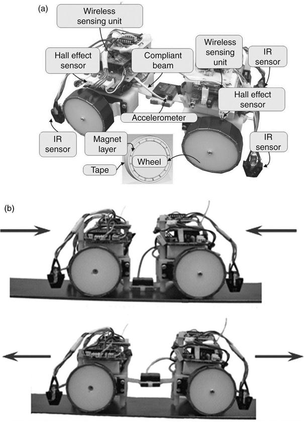
As shown in Fig. 15.11a, the wheels of the mobile sensing node are surrounded by thin magnets for providing sufficient attractive force to climb on ferromagnetic structures. Hall-effect sensors, which are capable of measuring the flux of a magnetic field, are fixed above the magnet wheels. As the wheel rotates, the north and south poles of the small magnets sequentially pass underneath the Hall-effect sensor. Therefore, the magnetic flux density measured by the Hall-effect sensor changes periodically, and the angular velocity of the wheel can be derived and then controlled in real time. In order to move the mobile sensing node (both forward and backward) safely on the underlying structural surface, infrared (IR) sensors are placed at both left and right sides of the front and rear two-wheel cars for surface boundary detection. When an IR sensor moves outside the surface boundary, changes can be captured from the strength of the reflected IR signal, so that the movement direction can be immediately corrected. Real-time feedback control of the motors is performed by the wireless sensing units.
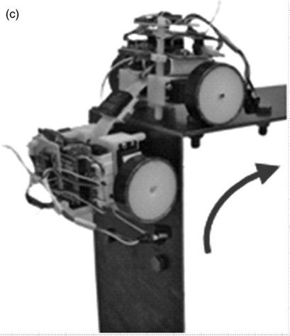
The other feature of the mobile sensing node is the ability to offer accurate acceleration measurement by firmly attaching the accelerometer onto the structural surface (Fig. 15.11b). The attaching procedure is achieved by commanding the two cars to move towards each other to bend the center of the compliant beam towards the structural surface. In addition, small-size magnet pieces are arranged around the center of the beam to further firmly attach the accelerometer onto the steel structural surface. After measurement, the two cars move in opposite directions to straighten the beam and lift the accelerometer away from the steel surface. After the accelerometer is lifted, the mobile sensing node resumes its mobility and moves to next location for another measurement. In addition, the compliant beam facilitates corner negotiation by the mobile sensing node (Fig. 15.11c). When the mobile sensing node climbs over a sharp corner, the front car and back car assist each other through the compliant connection beam. Thus, additional safety is achieved for corner negotiation, when comparing the compliant mechanism to a rigid body design. Detailed mechanical analysis for the compliant mechanism can be found in Guo et al. (2012).
Laboratory validation experiments for structural damage detection
A laboratory steel portal frame is constructed (Fig. 15.12). The span of the portal frame is 1.524 m (5 ft.) and the height is 0.914 m (3 ft.). The beam and two columns have the same rectangular section area of 0.152 m (6 in.) × 0.005 m (3/16 in.). Hinge connection is adopted at the base of each column. Each column is connected with the beam through a bolted angle plate, with four bolts on the beam and four bolts on the column. The torque of every bolt is initially set at 13.56 Nm (120 lbs-in.) for the undamaged structure.
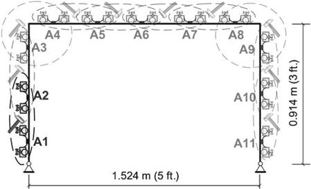
As shown in Fig. 15.12, two mobile sensing nodes are used to sequentially take measurements at every pair of locations (A1–A2, A2–A3,…, A10–A11). In the experiments, when the two mobile sensing nodes arrive at one pair of measurement locations, the accelerometers carried by both mobile nodes are attached onto the structural surface. A hammer impact is then applied at the middle of these two adjacent measurement locations. Impact responses at these two locations are recorded by the mobile sensing nodes. The mobile sensing nodes can either transmit the measurement data to the server, or conduct onboard analysis. After finishing the task at one location pair, the two mobile sensing nodes detach accelerometers from the structural surface, and move to the next pair of locations for next set of measurements. The sampling rate for acceleration measurement is assigned to be 2500 Hz.
Transmissibility function analysis, which can identify damage with output data only, is used to process the mobile sensor data for damage detection, (Zhang et al., 1999; Johnson et al., 2004; Kess and Adams, 2007; Devriendt and Guillaume, 2008). If external excitation is only applied at the k-th DOF, the transmissibility function Tij(ω) between the DOF i and reference-DOF j is defined as the ratio between the frequency spectra of the acceleration at DOFi and DOF j, Ai(ω) and Aj(ω):
[15.6]
It can be derived that for single excitation (at the k-th DOF), the transmissibility function is equivalent to the ratio between two entries of the frequency response function (FRF) matrix, Hik(ω) and Hjk(ω):
[15.7]
Equation [15.7] illustrates that transmissibility functions corresponding to inherent dynamic properties of the structure, and is independent of the excitation amplitude. In addition, Equation [15.6] shows that during experiments, the determination of transmissibility functions does not require measuring the excitation force. In order to reduce the effect of experimental uncertainties, the vibration experiments are repeated for N times (N = 20 in this study). Then the average transmissibility function ![]() is calculated:
is calculated:
[15.8]
where (Tij)l represents the transmissibility function Tij calculated from the l-th repeated test at DOFs i and j The damage indicator (DI) between DOFs i and j is defined as following:
[15.9]
 [15.9]
where ω1 and ω2 are the lower and upper boundaries of the interested frequency span; ![]() represents the average transmissibility function of the undamaged structure;
represents the average transmissibility function of the undamaged structure; ![]() represents the average transmissibility function of the damaged structure; ‘ln’ means natural logarithm. In this experimental study, ω1 and ω2 are set to 100 and 1000 Hz, respectively.
represents the average transmissibility function of the damaged structure; ‘ln’ means natural logarithm. In this experimental study, ω1 and ω2 are set to 100 and 1000 Hz, respectively.
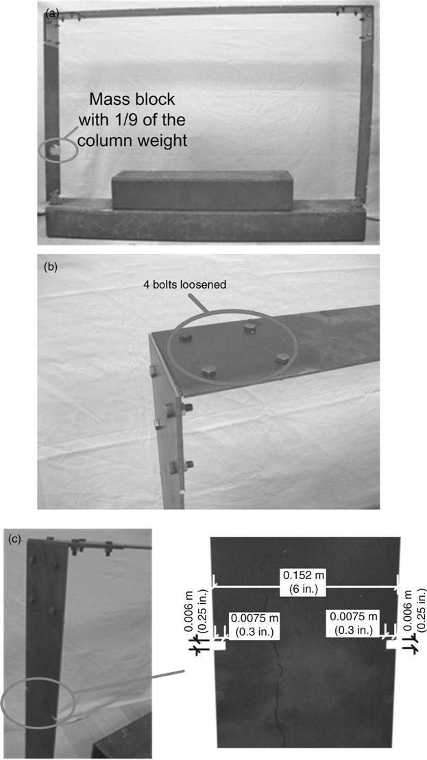
Three damage scenarios are studied. In Damage Scenario I (Fig. 15.13a), a steel mass block of 0.575 kg (1.27 lbs) is bonded at the left column between locations A1 and A2 (as marked in Fig. 15.12) for simulating a reversible damage. In contrast, the mass of the left column is 4.985 kg (10.99 lbs). In Damage Scenario II, four bolts at the upper left corner of the structure, which connect the beam and the angle plate, are loosened (Fig. 15.13b). The torque of each of the four bolts is reduced from 13.56 Nm (120 lbs-in.) to 0.565 Nm (5 lbs-in.). In Damage Scenario III, reduction in section area is introduced to the left column (Fig. 15.13c). The width of the section reduction is 0.006 m (0.25 in.), and the total length of the reduction is 0.0075 + 0.0075 = 0.015 m (0.6 in.). The location of the section reduction is at 0.533 m (21 in.) above the column base, which is between locations A2 and A3 marked in Fig. 15.12.
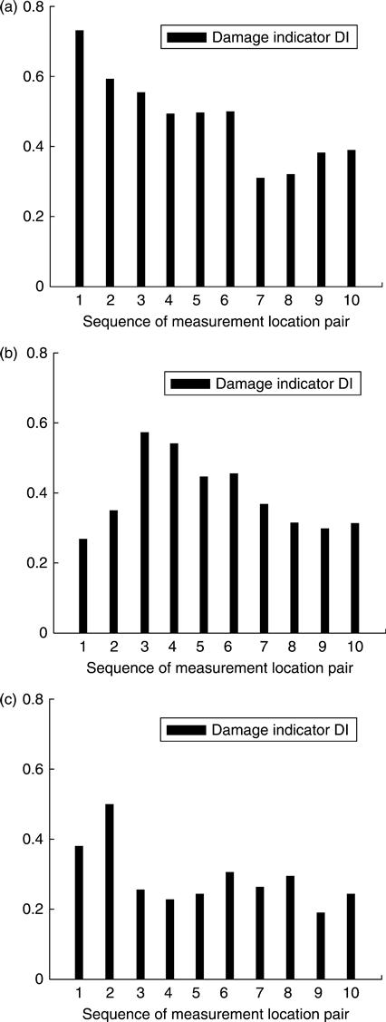
During the experiment for both the undamaged and damaged structures, the two mobile sensing nodes take measurement at every pair of locations (A1–A2, A2–A3,…,A10–A11) in sequence, and measurement at each location pair is repeatedly taken for 20 times. With all the experimental data sets, the average transmissibility functions for both the undamaged and damaged structures are computed for all ten location pairs using Equations [15.6] and [15.8]. The DIs are then obtained by Equation [15.9], and shown in Fig. 15.14. For each damage scenario, the sequence number of the location pair with the largest DI agrees with the correct damage location. For example, the largest DI in Damage Scenario II occurs at the third location pair i.e. locations A3–A4. This corresponds to the upper left corner of the frame where the bolts are loosened. It is demonstrated that using the high resolution data collected by a small number of mobile sensors, accurate damage detection has been achieved.
Field validation experiments for vibration modal analysis
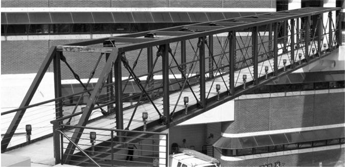
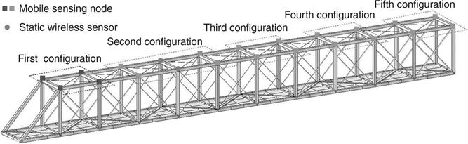
Field deployment of the flexure-based mobile sensing nodes is carried out on a steel pedestrian bridge (Zhu et al., 2011). The bridge consists of eleven chord units, each unit 9 ft. long. The length, width, and height of the bridge are 99, 7, and 9 ft., respectively (Fig. 15.15). The frame members are made of square tubes with cross section dimension of 6 in. × 6 in. Diagonal bracing members are allocated in vertical side planes and horizontal planes of the frame for enhancing structural stiffness.
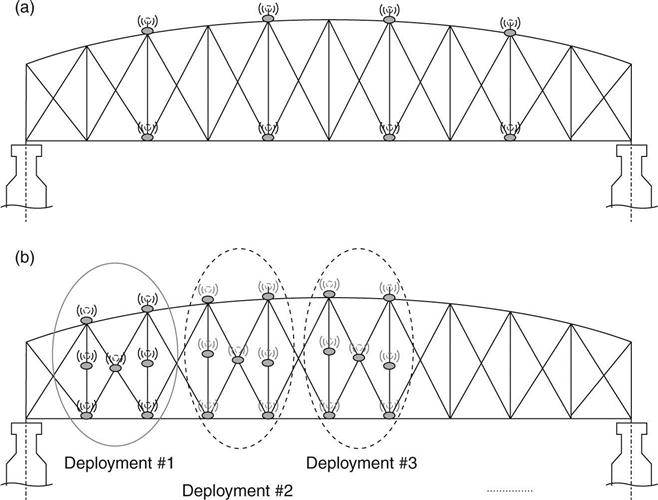
Four mobile sensing nodes are deployed in this experiment for navigating on the top plane of the frame. A total of five measurement configurations are adopted for the mobile sensing nodes. As shown in Fig. 15.16, each mobile configuration consists of four measurement locations. Two static wireless sensors are mounted as reference nodes for assembling the mode shapes of the bridge. At each measurement configuration, the mobile sensing nodes attach accelerometers onto the structural surface, and measure structural vibrations in the vertical direction.
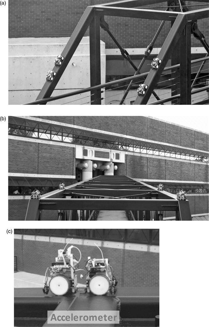
During testing, the mobile sensing nodes start from the inclined members at one side of the bridge (Fig. 15.17a), climb up over the corner, and then move to the first measurement configuration (Fig. 15.17b). Figure 15.17c shows a mobile sensing node that has attached an accelerometer onto the structural surface for vibration measurement. A vertical hammer impact is applied around the center of the bridge span. Acceleration data are collected by the mobile sensors at 200 Hz sampling rate, and wirelessly transmitted to a laptop server located at one side of the bridge. After finishing the measurement at the first configuration, the four mobile sensing nodes move to the second configuration and so on, till they cover the entire bridge span. At each configuration, the hammer impact and data collection procedures are repeatedly performed.
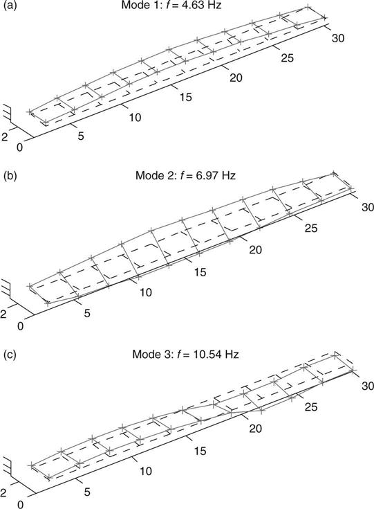
Upon data collection, the eigensystem realization algorithm (ERA) is applied to the mobile sensor data for extracting modal characteristics at each configuration (Juang and Pappa, 1985). The mode shapes of the entire bridge are assembled through the reference nodes with static wireless sensors. Figure 15.18 shows the first three mode shapes of the bridge that have significant vertical components. The first vertical mode shape shows all nodes moving along one direction, which is expected for such a simply supported bridge. With increasing complexities, other modes also agree with typical behavior of this type of structures. The field study again validated the performance of the mobile sensor network in collecting high spatialresolution data, with a limited number of sensing nodes and consuming little human effort.
15.5 Conclusions and future trends
Technological advances are providing unprecedented opportunities for adopting miniature robots for SHM applications. Carrying a variety of small-size sensors, SHM robots with unique locomotion systems can provide autonomous mobility while inspecting structures. Examples of different locomotion mechanisms include wheeled robots moving on horizontal surfaces, wall-climbing and crawling robots, snake-like robots, modular robots, aerial vehicles, underwater vehicles, etc. Various sensors, such as cameras, optical scanners, and their combinations have been incorporated for structural inspection purposes. SHM or inspection robots have been applied to different target structures, such as aircrafts, bridges and bridge cables, power lines, pipelines, ducts, tubes, sewage, etc.
In this chapter, vision-based robotic sensing for SHM was surveyed in depth as one of the emerging research field due to the recent advancement of the vision-based technology. The recent break-through in depth-image (RGB-depth) sensor technology is expected to boost up the related research. Remote robotic sensing might be another interesting research topic, thanks to the progress in wireless sensing and WPT technologies.
This chapter also presented exploratory work harnessing mobile sensor networks for SHM. Two mobile sensor nodes are demonstrated to first navigate on a laboratory portal frame. Cross-correlation function analysis is applied to mobile sensor data for damage detection and location. During field testing, a four-node mobile sensor network is used to navigate autonomously to different sections of a steel bridge, for measuring vibrations due to hammer impact and ambient excitation at high spatial resolution. Modal analysis is successfully conducted using the mobile sensor data.
Although robots specialized for SHM application have only recently been developed, their use is expected to largely increase in the near future. New SHM markets will be opened by equipping agile robot systems with advanced sensor technologies. In general, future work can be devoted to both implementation and analysis. With respect to implementation, more agile mobile sensors are needed for navigating on complicated real-world structures. In addition, a mobile excitation node can be developed for applying small-magnitude impact forces to one local area of a structure. With respect to analysis, efficient damage detection or condition evaluation algorithms are needed in order to best utilize high-density measurements provided by a group of mobile sensors. For example, substructure-based finite element model updating algorithms can be developed for efficiently analyzing dense mobile sensor data collected from one section of a large structure.