
17. Designing an Architecture
In most people’s vocabularies, design means veneer. It’s interior decorating. It’s the fabric of the curtains or the sofa. But to me, nothing could be further from the meaning of design. Design is the fundamental soul of a human-made creation that ends up expressing itself in successive outer layers of the product or service.
—Steve Jobs
We have discussed the building blocks for designing a software architecture, which principally are locating architecturally significant requirements; capturing quality attribute requirements; and choosing, generating, tailoring, and analyzing design decisions for achieving those requirements. All that’s missing is a way to pull the pieces together. The purpose of this chapter is to provide that way.
We begin by describing our strategy for designing an architecture and then present a packaging of these ideas into a method: the Attribute-Driven Design method.
17.1. Design Strategy
We present three ideas that are key to architecture design methods: decomposition, designing to architecturally significant requirements, and generate and test.
Decomposition
Architecture determines the quality attributes of a system. Hopefully, we have convinced you of that by now. The quality attributes are properties of the system as a whole. Latency, for example, is the time between the arrival of an event and the output of the processing of that event. Availability refers to the system providing services, and so forth.
Given the fact that quality attributes refer to the system as a whole, if we wish to design to achieve quality attribute requirements, we must begin with the system as a whole. As the design is decomposed, the quality attribute requirements can also be decomposed and assigned to the elements of the decomposition.
A decomposition strategy does not mean that we are assuming the design is a green-field design or that there are no constraints on the design to use particular preexisting components either externally developed or legacy. Just as when you choose a route from one point to another, you may choose to stop at various destinations along the route, constraints on the design can be accommodated by a decomposition strategy. You as the designer must keep in mind the constraints given to you and arrange the decomposition so that it will accommodate those constraints. In some contexts, the system may end up being constructed mostly from preexisting components; in others, the preexisting components may be a smaller portion of the overall system. In either case, the goal of the design activity is to generate a design that accommodates the constraints and achieves the quality and business goals for the system.
We have already talked about module decomposition, but there are other kinds of decompositions that one regularly finds in an architecture, such as the decomposition of a component in a components-and-connectors (C&C) pattern into its subcomponents. For example, a user interface implemented using the model-view-controller (MVC) pattern would be decomposed into a number of components for the model, one or more views, and one or more controllers.
Designing to Architecturally Significant Requirements
In Chapter 16, we discussed architecturally significant requirements (ASRs) and gave a technique for collecting and structuring them. These are the requirements that drive the architectural design; that is why they are significant. Driving the design means that these requirements have a profound effect on the architecture. In other words, you must design to satisfy these requirements. This raises two questions: What happens to the other requirements? and Do I design for one ASR at a time or all at once?
1. What about the non-ASR requirements? The choice of ASRs implies a prioritization of the requirements. Once you have produced a design that satisfies the ASRs, you know that you are in good shape. However, in the real world, there are other requirements that, while not ASRs, you would like to be able to satisfy. You have three options with respect to meeting these other requirements: (a) You can still meet the other requirements. (b) You can meet the other requirements with a slight adjustment of the existing design, and this slight adjustment does not keep the higher priority requirements from being met. (c) You cannot meet the other requirements under the current design. In case (a) or (b), there is nothing more to be done. You are happy. In case (c), you now have three options: (i) If you are close to meeting the requirement, you can see if the requirement can be relaxed. (ii) You can reprioritize the requirements and revisit the design. (iii) You can report that you cannot meet the requirement. All of these latter three options involve adjusting either the requirement or its priority. Doing so may have a business impact, and it should be reported up the management chain.
2. Design for all of the ASRs or one at a time? The answer to this question is a matter of experience. When you learn chess, you begin by learning that the horsey goes up two and over one. After you have been playing for a while, you internalize the moves of the knight and you can begin to look further ahead. The best players may look ahead a dozen or more moves. This situation applies to when you are designing to satisfy ASRs. Left to their own devices, novice architects will likely focus on one ASR at a time. But you can do better than that. Eventually, through experience and education, you will develop an intuition for designing, and you will employ patterns to aid you in designing for multiple ASRs.
Generate and Test
One way of viewing design is as a process of “generate and test.” This generate-and-test approach views a particular design as a hypothesis: namely, the design satisfies the requirements. Testing is the process of determining whether the design hypothesis is correct. If it is not, then another design hypothesis must be generated. Figure 17.1 shows this iteration.
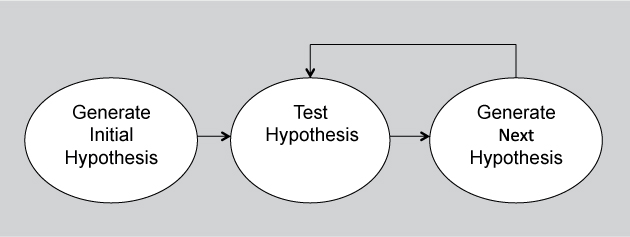
Figure 17.1. The generate-and-test process of architecture design
For this process to be effective, the generation of the next design hypothesis must build on the results of the tests. That is, the things wrong with the current design hypothesis are fixed in the next design hypothesis, and the things that are right are kept. If there is no coupling between the testing and the generation of the next design hypothesis, then this process becomes “guess and test” and that is not effective.
Generate and test as a design strategy leads to the following questions:
1. Where does the initial hypothesis come from?
2. What are the tests that are applied?
3. How is the next hypothesis generated?
4. When are you done?
We have already seen many of the elements of the answers to these questions. But now we can think about them and organize them more systematically.
Creating the Initial Hypothesis
Design solutions are created using “collateral” that is available to the project. Collateral can include existing systems, frameworks available to the project, known architecture patterns, design checklists, or a domain decomposition.
• Existing systems. Very few systems are completely unprecedented, even within a single organization. Organizations are in a particular business, their business leads to specialization, and specialization leads to the development of variations on a theme. It is likely that systems already exist that are similar to the system being constructed in your company.
Existing systems are likely to provide the most powerful collateral, because the business context and requirements for the existing system are likely to be similar to the business context and requirements for the new system, and many of the problems that occur have already been solved in the existing design.
A common special case is when the existing system you’re drawing on for knowledge is the same one that you’re building. This occurs when you’re evolving a system, not building one from scratch. The existing design serves as the initial design hypothesis. The “test” part of this process will reveal the parts that don’t work under the current (presumably changed) set of requirements and will therefore pinpoint the parts of the system’s design that need to change.
Another special case is when you have to combine existing legacy systems into a single system. In this case, the collection of legacy systems can be mined to determine the initial design hypothesis.
• Frameworks. A framework is a partial design (accompanied by code) that provides services that are common in particular domains. Frameworks exist in a great many domains, ranging from web applications to middleware systems to decision support systems. The design of the framework (especially the architectural assumptions it makes) provides the initial design hypothesis. For example, a design framework might constrain all communication to be via a broker, or via a publish-subscribe bus, or via callbacks. In each case this design framework has constrained your initial design hypothesis.
• Patterns and tactics. As we discussed in Chapter 13, a pattern is a known solution to a common problem in a given context. Cataloged architectural patterns, possibly augmented with tactics, should be considered as candidates for the design hypothesis you’re building.
• Domain decomposition. Another option for the initial design hypothesis comes from performing a domain decomposition. For example, most object-oriented analysis and design processes begin this way, identifying actors and entities in the domain. This decomposition will divide the responsibilities to make certain modifications easier, but by itself it does not speak to many other quality attribute requirements.
• Design checklists. The design checklists that we presented in Chapters 5–11 can guide an architect to making quality-attribute-targeted design choices. The point of using a checklist is to ensure completeness: Have I thought about all of the issues that might arise with respect to the many quality attribute concerns that I have? The checklist will provide guidance and confidence to an architect.
Choosing the Tests
Three sources provide the tests to be applied to the hypothesis:
1. The analysis techniques described in Chapter 14.
2. The design checklists for the quality attributes that we presented in Chapters 5–11 can also be used to test the design decisions already made, from the sources listed above. For the important quality attribute requirements, use the design checklists to assess whether the decisions you’ve made so far are sound and complete. For example, if testability is important for your system, the checklist says to ensure that the coordination model supports capturing the activity that led to a fault.
3. The architecturally significant requirements. If the hypothesis does not provide a solution for the ASRs, then it must be improved.
Generating the Next Hypothesis
After applying the tests, you might be done—everything looks good. On the other hand, you might still have some concerns; specifically, you might have a list of quality attribute problems associated with your analysis of the current hypothesis. This is the problem that tactics are intended to solve: to improve a design with respect to a particular quality attribute. Use the sets of tactics described in each of Chapters 5–11 to help you to choose the ones that will improve your design so that you can satisfy these outstanding quality attribute requirements.
Terminating the Process
You are done with the generate-and-test process when you either have a design that satisfies the ASRs or when you exhaust your budget for producing the design. In Chapter 22, we discuss how much time should be budgeted for producing the architecture.
If you do not produce such a design within budget, then you have two options depending on the set of ASRs that are satisfied. Your first option is to proceed to implementation with the best hypothesis you were able to produce, with the realization that some ASRs may not be met and may need to be relaxed or eliminated. This is the most common case. Your second option is to argue for more budget for design and analysis, potentially revisiting some of the major early design decisions and resuming generate and test from that point. If all else fails, you could suggest that the project be terminated. If all of the ASRs are critical and you were not able to produce an acceptable or nearly acceptable design, then the system you produce from the design will not be satisfactory and there is no sense in producing it.
17.2. The Attribute-Driven Design Method
The Attribute-Driven Design (ADD) method is a packaging of the strategies that we have just discussed. ADD is an iterative method that, at each iteration, helps the architect to do the following:
• Choose a part of the system to design.
• Marshal all the architecturally significant requirements for that part.
• Create and test a design for that part.
The output of ADD is not an architecture complete in every detail, but an architecture in which the main design approaches have been selected and vetted. It produces a “workable” architecture early and quickly, one that can be given to other project teams so they can begin their work while the architect or architecture team continues to elaborate and refine.
Inputs to ADD
Before beginning a design process, the requirements—functional, quality, and constraints—should be known. In reality, waiting for all of the requirements to be known means the project will never be finished, because requirements are continually arriving to a project as a result of increased knowledge on the part of the stakeholders and changes in the environment (technical, social, legal, financial, or political) over time. ADD can begin when a set of architecturally significant requirements is known.
This increases the importance of having the correct set of ASRs. If the set of ASRs changes after design has begun, then the design may well need to be reworked (a truth under any design method, not just ADD). To the extent that you have any influence over the requirements-gathering process, it would behoove you to lobby for collection of ASRs first. Although these can’t all be known a priori, as we saw in Chapter 16, quality attribute requirements are a good start.
In addition to the ASRs, input to ADD should include a context description. The context description gives you two vital pieces of information as a designer:
1. What are the boundaries of the system being designed? What is inside the system and what is outside the system must be known in order to constrain the problem and establish the scope of the architecture you are designing. The system’s scope is unknown or unclear surprisingly often, and it will help the architecture to nail down the scope as soon as you can.
2. What are the external systems, devices, users, and environmental conditions with which the system being designed must interact? By “environmental conditions” here we are referring to the system’s runtime environment. The system’s environmental conditions are an enumeration of factors such as where the input comes from, where the output goes, what forms they take, what quality attributes they have, and what forces may affect the operation of the system. It is possible that not all of the external systems are known at design time. In this case, the system must have some discovery mechanisms, but the context description should enumerate the assumptions that can be made about the external systems even if their specifics are not yet known. An example of accommodating environment conditions can be seen in a system that must be sent into space. In addition to handling its inputs, outputs, and quality attributes, such a system must accommodate failures caused by stray gamma rays, certainly a force affecting the operation of the system.
Output of ADD
The output of ADD is a set of sketches of architectural views. The views together will identify a collection of architectural elements and their relationships or interactions. One of the views produced will be a module decomposition view, and in that view each element will have an enumeration of its responsibilities listed.
Other views will be produced according to the design solutions chosen along the way. For example, if at one point in executing the method, you choose the service-oriented architecture (SOA) pattern for part of the system, then you will capture this in an SOA view (whose scope is that part of the system to which you applied the pattern).
The interactions of the elements are described in terms of the information being passed between the elements. For example, we might specify protocol names, synchronous, asynchronous, level of encryption, and so forth.
The reason we refer to “sketches” above is that ADD does not take the design so far as to include full-blown interface specifications, or even so far as choosing the names and parameter types of interface programs (methods). That can come later. ADD does identify the information that passes through the interfaces and important characteristics of the information. If any aspects of an interface have quality attribute implications, those are captured as annotations.
When the method reaches the end, you will have a full-fledged architecture that is roughly documented as a set of views. You can then polish this collection, perhaps merging some of the views as appropriate, to the extent required by your project. In an Agile project, this set of rough sketches may be all you need for quite a while, or for the life of the project.
17.3. The Steps of ADD
ADD is a five-step method:
1. Choose an element of the system to design.
2. Identify the ASRs for the chosen element.
3. Generate a design solution for the chosen element.
4. Inventory remaining requirements and select the input for the next iteration.
5. Repeat steps 1–4 until all the ASRs have been satisfied.
Step 1: Choose an Element of the System to Design
ADD works by beginning with a part of the system that has not yet been designed, and designing it. In this section, we’ll discuss how to make that choice.
For green-field designs, the “element” to begin with is simply the entire system. The first trip through the ADD steps will yield a broad, shallow design that will produce a set of newly identified architectural elements and their interactions. These elements will almost certainly require more design decisions to flesh out what they do and how they satisfy the ASRs allocated to them; during the next iteration of ADD, those elements become candidates for the “choose an element” step.
So, nominally, the first iteration of ADD will create a collection of elements that together constitute the entire system. The second iteration will take one of these elements—what we call the “chosen element”—and design it, resulting in still finer-grained elements. The third iteration will take another element—either one of the children of the whole system or one of the children that was created from the design of one of the children of the whole system—and so forth. For example, if you choose an SOA pattern in the first iteration, you might choose child elements such as service clients, service providers, and the SOA infrastructure components. In the next iteration through the loop, you would refine one of these child elements, perhaps the infrastructure components. In the next iteration you now have a choice: refine another child of the SOA pattern, such as a service provider, or refine one of the child elements of the infrastructure components. Figure 17.2 shows these choices as a decomposition tree, annotated with the ADD iteration that applies to each node. (The example components are loosely based on the Adventure Builder system, introduced in Chapter 13.) Figure 17.2 is a decomposition view of our hypothetical system after two iterations of ADD.
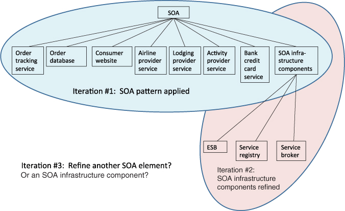
Figure 17.2. Iteration 1 applied the SOA pattern. Iteration 2 refined the infrastructure components. Where will iteration 3 take you?
There are cases when the first iteration of ADD is different. Perhaps you are not creating a system but evolving an existing one. Perhaps you are required to use a piece of software that your company already owns, and therefore must fit it into the design. There are many reasons why some of the design might already be done for you, and the first time through the steps of ADD you won’t pick “whole system” as the starting point. Nevertheless, step 1 still holds: All it requires is that at least one of the elements you know about needs further design.
There are two main refinement strategies to pursue with ADD: breadth first and depth first. Breadth first means that all of the second-level elements are designed before any of the third-level elements, and so forth. Depth first means that one downward chain is completed before beginning a second downward chain. The order that you should work through ADD is influenced by the business and technical contexts within which the project is operating. Some of the important factors include the following:
• Personnel availability may dictate a refinement strategy. If an important group or team has a window of availability that will close soon and will work on a particular part of the system, then it behooves the architect to design that part of the system to the point where it can be handed off for implementation—depth first. But if the team is not currently available but will be available at some definite time in the future, then you can defer their part of the design until later.
• Risk mitigation may dictate a refinement strategy. The idea is to design the risky parts of the system to enough depth so that problems can be identified and solved early. For example, if an unfamiliar technology is being introduced on the project, prototypes using that technology will likely be developed to gain understanding of its implications. These prototypes are most useful if they reflect the design of the actual system. A depth-first strategy can provide a context for technology prototyping. Using this context you can build the prototype in a fashion that allows for its eventual integration into the architecture. On the other hand, if the risk is in how elements at the same level of the design interact with each other to meet critical quality attributes, then a breadth-first strategy is in order.
• Deferral of some functionality or quality attribute concerns may dictate a mixed approach. For example, suppose the system being constructed has a medium-priority availability requirement. In this case you might adopt a strategy of employing redundancy for availability but defer detailed consideration of this redundancy strategy to allow for the rapid generation of the high-priority functionality in an intermediate release. You might therefore apply a breadth-first approach for everything but availability, and then in subsequent design iterations you revisit some of the elements to enable the addition of the responsibilities to support availability. In reality this approach will require some backtracking, where you revisit earlier decisions and refine them or modify them to accommodate this new requirement.
All else being equal, a breadth-first refinement strategy is preferred because it allows you to apportion the most work to the most teams soonest. Breadth first allows for consideration of the interaction among the elements at the same level.
Step 2: Identify the ASRs for This Element
In Chapter 16 we described a number of methods for discovering the ASRs for a system. One of those methods involved building a utility tree. To support the design process, the utility tree has an advantage over the other methods: it guides the stakeholders in prioritizing the QA requirements. The two factors used to prioritize the ASRs in a utility tree are business value and architectural impact. The business value of an ASR typically will not change throughout the design process and does not need to be reconsidered.
If the chosen element for design in step 1 is the whole system, then a utility tree can be a good source for the ASRs. Otherwise, construct a utility tree specifically focused on this chosen element, using the quality attribute requirements that apply to this element (you’ll see how to assign those in step 4). Those that are labeled (High, High) are the ASRs for this element. As an architect you will also need to pay attention to the (High, Medium) and (Medium, High) utility tree leaves as well. These will almost certainly also be ASRs for this element.
Step 3: Generate a Design Solution for the Chosen Element
This step is the heart of the ADD. It is the application of the generate-and-test strategy. Upon entry to this step, we have a chosen element for design and a list of ASRs that apply to it. For each ASR, we develop a solution by choosing a candidate design approach.
Your initial candidate design will likely be inspired by a pattern, possibly augmented by one or more tactics. You may then refine this candidate design by considering the design checklists that we gave for the quality attributes in Chapters 5–11. For ASRs that correspond to quality attributes, you can invoke those checklists to help you instantiate or refine the major design approach (such as a pattern) that you’ve chosen. For example, the layered pattern is helpful for building systems in which modifiability is important, but the pattern does not tell you how many layers you should have or what each one’s responsibility should be. But the checklist for the “allocation of responsibilities” design decision category for modifiability in Chapter 7 will help you ask the right questions to make that determination.
Although this step is performed for each ASR in turn, the sources of design candidates outlined above—patterns, tactics, and checklists—will usually do much better than that. That is, you’re likely to find design candidates that address several of your ASRs at once. This is because to the extent that the system you’re building is similar to others you know about, or to the extent that the problem you are solving is similar to the problems solved by patterns, it is likely that the solutions you choose will be solving a whole collection of ASRs simultaneously. If you can bring a solution to bear that solves more than one of your ASRs at once, so much the better.
The design decisions made in this step now become constraints on all future steps of the method.
Step 4: Verify and Refine Requirements and Generate Input for the Next Iteration
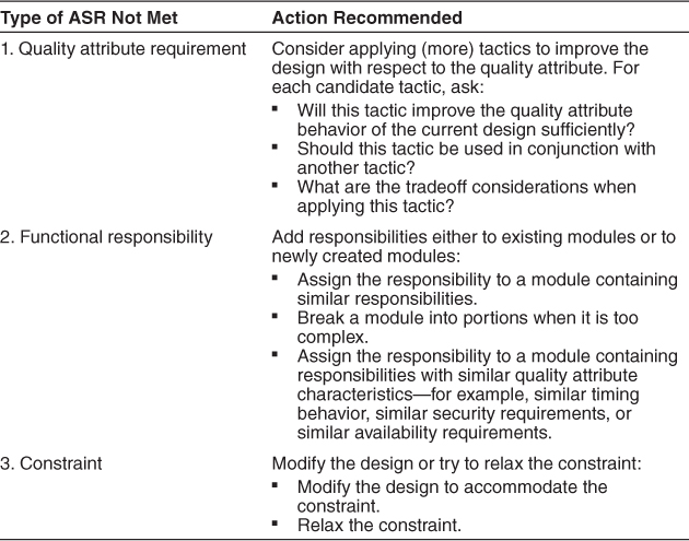
It’s possible that the design solution you came up with in the prior step won’t satisfy all the ASRs. Step 4 of ADD is a test step that is applied to your design for the element you chose to elaborate in step 1 of this iteration. One of the possible outcomes of step 4 is “backtrack,” meaning that an important requirement was not satisfied and cannot be satisfied by further elaborating this design. In this case, the design needs to be reconsidered.
The ASRs you have not yet satisfied could be related to the following:
1. A quality attribute requirement allocated to the parent element
2. A functional responsibility of the parent element
3. One or more constraints on the parent element
Table 17.1 summarizes the types of problems and the actions we recommend for each.
Table 17.1. Recommended Actions for Problems with the Current Hypothesis
In most real-world systems, requirements outstrip available time and resources. Consequently you will find yourself unable to meet some of the QA requirements, functional requirements, and constraints. These kinds of decisions are outside the scope of the ADD method, but they are clearly important drivers of the design process, and as an architect you will be continually negotiating decisions of this form.
Step 4 is about taking stock and seeing what requirements are left that still have not been satisfied by our design so far. At this point you should sequence through the quality attribute requirements, responsibilities, and constraints for the element just designed. For each one there are four possibilities:
1. The quality attribute requirement, functional requirement, or constraint has been satisfied. In this case, the design with respect to that requirement is complete; the next time around, when you further refine the design, this requirement will not be considered. For example, if a constraint is to use a particular middleware and the system is decomposed into elements that all use this middleware, the constraint has been satisfied and can be removed from consideration. An example of a quality attribute requirement being satisfied is a requirement to make it easy to modify elements and their interactions. If a publish-subscribe pattern can be shown to have been employed throughout the system, then this QA requirement can be said to be satisfied.
2. The quality attribute requirement, functional requirement, or constraint is delegated to one of the children. For example, if a constraint is to use a particular middleware and the decomposition has a child element that acts as the infrastructure, then delegating that constraint to that child will retain the constraint and have it be reconsidered when the infrastructure element is chosen for subsequent design. Similarly, with the example we gave earlier about providing extensibility, if there is as yet no identifiable plug-in manager, then this requirement is delegated to the child where the plug-in manager is likely to appear.
3. The quality attribute requirement, functional requirement, or constraint is distributed among the children. For example, a constraint might be to use .NET. In this case, .NET Remoting might become a constraint on one child and ASP.NET on another. Or a quality attribute requirement that constrains end-to-end latency of a certain operation to 2 seconds could be distributed among the element’s three children so that the latency requirement for one element is 0.8 seconds, the latency for a second element is 0.9 seconds, and the latency for a third is 0.3 seconds. When those elements are subsequently chosen for further design, those times will serve as constraints on them individually.
4. The quality attribute requirement, functional requirement, or constraint cannot be satisfied with the current design. In this case there are the same two options we discussed previously: you can either backtrack—revisit the design to see if the constraint or quality attribute requirement can be satisfied some other way—or push back on the requirement. This will almost certainly involve the stakeholders who care about that requirement, and you should have convincing arguments as to why the dropping of the requirement is necessary.
Report to the project manager that the constraint cannot be satisfied without jeopardizing other requirements. You must be prepared to justify such an assertion. Essentially, this is asking, “What’s more important—the constraint or these other requirements?”
Step 5: Repeat Steps 1–4 Until Done
After the prior steps, each element has a set of responsibilities, a set of quality attribute requirements, and a set of constraints assigned to it. If it’s clear that all of the requirements are satisfied, then this unequivocally ends the ADD process.
In projects in which there is a high degree of trust between you and the implementation teams, the ADD process can be terminated when only a sketch of the architecture is available. This could be as soon as two levels of breadth-first design, depending on the size of the system. In this case, you trust the implementation team to be able to flesh out the architecture design in a manner consistent with the overall design approaches you have laid out. The test for this is if you believe that you could begin implementation with the level of detail available and trust the implementation team to that extent. If you have less trust in the implementation team, then an additional level (or levels) of design may be necessary. (And, of course, you will need to subsequently ensure that the implementation is faithfully followed by the team.)
On the other hand, if there is a contractual arrangement between your organization and the implementation organization, then the specification of the portion of the system that the implementers are providing must be legally enforceable. This means that the ADD process must continue until that level of specificity has been achieved.
Finally, another condition for terminating ADD is when the project’s design budget has been exhausted. This happens more often than you might think.
Choosing when to terminate ADD and when to start releasing the architecture that you’ve sketched out are not the same decision. You can, and in many cases should, start releasing early architectural views based on the needs of the project (such as scheduled design reviews or customer presentations) and your confidence in the design so far. The unpalatable alternative is to make everyone wait until the architecture design is finished. You-can’t-have-it-until-it’s-done is particularly unpalatable in Agile projects, as we discussed in Chapter 15.
You should release the documentation with a caveat as to how likely you think it is to change. But even early broad-and-shallow architectural descriptions can be enormously helpful to implementers and other project staff. A first- or second-level module decomposition view, for instance, lets experts start scouring the marketplace for commercial products that provide the responsibilities of the identified modules. Managers can start making budgets and schedules for implementation that are based on the architecture and not just the requirements. Support staff can start building the infrastructure and file systems to hold project artifacts (these are often structured to mirror the module decomposition view). And early release invites early feedback.
17.4. Summary
The Attribute-Driven Design method is an application of the generate-and-test philosophy. It keeps the number of requirements that must be satisfied to a humanly achievable quantity. ADD is an iterative method that, at each iteration, helps the architect to do the following:
• Choose an element of the system to design.
• Marshal all the architecturally significant requirements for the chosen element.
• Create and test a design for that chosen element.
The output of ADD is not an architecture complete in every detail, but an architecture in which the main design approaches have been selected and validated. It produces a “workable” architecture early and quickly, one that can be given to other project teams so they can begin their work while the architect or architecture team continues to elaborate and refine.
ADD is a five-step method:
1. Choose the element of the system to design. For green-field designs, the “part” to begin with is simply the entire system. For designs that are already partially completed (either by external constraints or by previous iterations through ADD), the part is an element that is not yet designed. Choosing the next element can proceed in a breadth-first, depth-first, or mixed manner.
2. Identify the ASRs for the chosen element.
3. Generate a design solution for the chosen element, using design collateral such as existing systems, frameworks, patterns and tactics, and the design checklists from Chapters 5–11.
4. Verify and refine requirements and generate input for the next iteration. Either the design in step 3 will satisfy all of the chosen element’s ASRs or it won’t. If it doesn’t, then either they can be allocated to elements that will be elaborated in future iterations of ADD, or the existing design is inadequate and we must backtrack. Furthermore, non-ASR requirements will either be satisfied, allocated to children, or indicated as not achievable.
5. Repeat steps 1–4 until all the ASRs have been satisfied, or until the architecture has been elaborated sufficiently for the implementers to use it.
17.5. For Further Reading
You can view design as the process of making decisions; this is another philosophy of design. This view of design leads to an emphasis on design rationale and tools to capture design rationale. The view of design as the process of making decisions dates to the 1940s [Mettler 91], but it has been recently applied to architecture design most prominently by Philippe Kruchten [Kruchten 04], and Hans van Vliet and Jan Bosch [van Vliet 05].
The Software Engineering Institute has produced a number of reports describing the ADD method and its application in a variety of contexts. These include [Wojcik 06], [Kazman 04], and [Wood 07].
George Fairbanks has written an engaging book that describes a risk-driven process of architecture design, entitled Just Enough Software Architecture: A Risk-Driven Approach [Fairbanks 10].
Tony Lattanze has created an Architecture-Centric Design Method (ACDM), described in his book Architecting Software Intensive Systems: A Practitioners Guide [Lattanze 08].
Ian Gorton’s Essential Architecture, Second Edition, emphasizes the middleware aspects of a design [Gorton 10].
Woods and Rozanski have written Software Systems Architecture, Second Edition, which interprets the design process through the prism of different views [Woods 11].
A number of authors have compared five different industrial architecture design methods. You can find this comparison at [Hofmeister 07].
Raghvinder Sangwan and his colleagues describe the design of a building management system that was originally designed using object-oriented techniques and then was redesigned using ADD [Sangwan 08].
17.6. Discussion Questions
1. ADD does not help with the detailed design of interfaces for the architectural elements it identifies. Details of an interface include what each method does, whether you need to call a single all-encompassing method to perform the work of the element or many methods of finer-grained function, what exceptions are raised on the interface, and more. What are some examples where the specific design of an interface might bring more or less performance, security, or availability to a system? (By the way, if there are quality attribute implications to an interface, you can capture those as annotations on the element.)
2. What sets a constraint apart from other (even high-priority) requirements is that it is not negotiable. Should this consideration guide the design process? For example, would it be wise to design to satisfy all of the constraints before worrying about other ASRs?
3. In discussion question 4 of Chapter 16 you were asked to create a utility tree for an ATM. Now choose the two most important ASRs from that utility tree and create a design fragment using the ADD method employing and instantiating a pattern.