
Chapter 7
Architecture and Detailed Design
7.1 Introduction
The previous chapters explored the architectural analysis and design of the building automation system and showed that using the architecture-centric approach we arrive at an architecture that supports the business and mission goals of the application. This approach, however, leaves the fine-grained design details unspecified. Although such details are not a necessary part of architectural design, it is essential to understand the relationship between high-level architectural design and low-level detailed design and see how development work transitions from one to the other.
The mainstream methodology used in practice for detailed design is object-oriented analysis and design (OOAD) (Larman, 2005). Much of our discussion in Chapter 3 on achieving a broad functional understanding of a system forms an important part of OOAD as well. For instance, the natural starting point for OOAD is also a system context and is used for enumerating all of its actors. The goals of the actors in how they want to use the system become the basis for defining the use cases. The use cases are then elaborated to distill the functional responsibilities that a system must support to fulfill that use case. The elaboration is guided by a problem domain model that captures significant conceptual entities from the problem domain that are created, used, updated, or destroyed during the execution of the use cases. The problem domain model also becomes a basis for a standard vocabulary of significant concepts that are then used consistently for expressing use cases. OOAD, however, leverages this information for creating two additional artifacts: interfaces and a domain object model.
7.2 Defining Interfaces
We used the functional responsibilities derived in this manner to allocate responsibilities to individual components that were created as a part of elaborating the architecture in Chapter 5. For OOAD, the functional responsibilities derived from a use case are used for creating two types of classes for that use case: a boundary class that represents the interface that is used to interact with the components within the system and a request handler or a controller class that coordinates the invocation of components within the system to get the work done for the given use case. The actor initiates a use case through the boundary class (by generating an event, for instance), and the boundary class forwards the request from a user (the event that was generated, for instance) to the controller; the controller must then coordinate the invocation of a series of methods on components within the system in response to that event.
7.3 Creating the Domain Object Model
The problem domain model developed in Chapter 3 was used to create a standard vocabulary of terms that can be used in a consistent expression of all use cases. In OOAD, the domain model also becomes a motivator for creating classes known as entity classes. The entity classes represent significant concepts from the domain and house any important information associated with these concepts along with rules or logic for manipulating that information. They are created, used, updated, or destroyed during the execution of various use cases within the system and contain information of significant value. Therefore, entity classes together constitute a domain object model that is persisted in a persistent data store whose schema closely resembles this model.
The domain object model lives inside various components of the building automation architecture created in Chapter 5. For instance, it is natural for the rule domain object to reside in the rule manager component and for the device domain object to reside in the virtual device component. The components therefore may themselves play a role of a domain object manager or contain a controller class that manages access to these domain objects.
We capture the essence of this discussion in Figure 7.1. The figure shows that a user request is received through the boundary object that plays a role of an interface, which forwards the request to the controller object that plays a role of a request handler, which in turn invokes system operations on one or more objects that play a role of the domain object manager, which in turn invoke methods on one or more objects that play a role of domain object. The request handler eventually returns a system response to a user request.
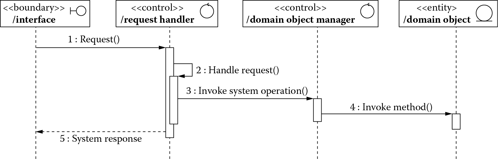
We illustrate this approach for the use case scenario in which a field device generates a change-of-value event (such as someone raises the temperature property value of a thermostat on a building floor) that must be processed by a rule manager for taking an appropriate action (such as turning on the heating unit for that floor).
7.3 The Rule Manager
Based on the conceptual pattern suggested in Figure 7.1, we consider the field device (i.e., the thermostat) to be the actor that generates a temperature change event that is first received by the virtual device component, a boundary class that plays the role of an interface into the building automation system. The virtual device publishes this event to the publish-subscribe connector, a controller class that plays the role of a request handler. It forwards the event to all those components that have subscribed to it. In our example, this happens to be the rule manager, a controller class that plays the role of a domain object manager. The rule manager invokes a rule evaluation method on one or more rule domain objects, and the results of this evaluation may suggest the rule manager further invoke a trigger method on one or more command domain objects to take the appropriate action. We show this conceptual sequence of actions in Figure 7.2.
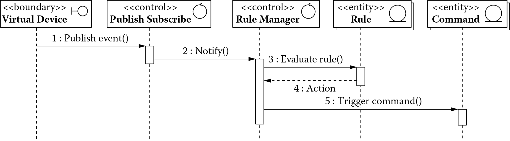
A conceptual sequence of actions triggered as a result of an event generated by a field device.
This conceptual sequence of actions can serve as a good backdrop to our understanding, and we may be tempted to start putting together our blueprint for implementing the rule manager. There are, however, a few other considerations that need to be made.
The distinction between architecture design and detailed design is in the mind of the beholder. What may be detailed design to one may well be architecture design to another. So, when the detailed design of the rule manager is assigned to a project team, they may first go through the same architecture-centric process, namely, attribute-driven design (Bass et al., 2013), which was followed in the previous chapters for the building automation system, and create the internal architecture of the rule manager to address any of its architectural responsibilities before they address its functional responsibilities. Table 7.1 shows all of these responsibilities.
Responsibilities of the Rule Manager
|
Responsibility |
Type |
Description |
|
Process multiple concurrent events |
Architectural |
A building automation system can have configurations ranging from 500 to 500,000 field devices, which can generate considerable load on the system. To minimize the latency in processing events generated from these devices, they must be processed concurrently. |
|
Evaluate and execute automation rules |
Functional |
Rules have a condition and an action. The condition specifies a threshold or value for one or more properties of one or more field devices that must be true for the action to be triggered. The action specifies commands that must be executed. |
|
Send automation commands |
Functional |
The commands to be executed in response to an action must be dispatched to the appropriate field devices. |
Table 7.1 is provided as an input to a project team, which they use to drive the design and development of the rule manager. We first create the internal architecture of the rule manager to address its architectural responsibilities. Then, we tackle the functional responsibilities.
7.3.1 Addressing Architectural Responsibilities
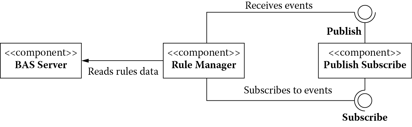
Our starting point would be the rule manager and its context (the other elements of the system with which it interacts) as presented in the final architecture of the building automation system. We show this in Figure 7.3.
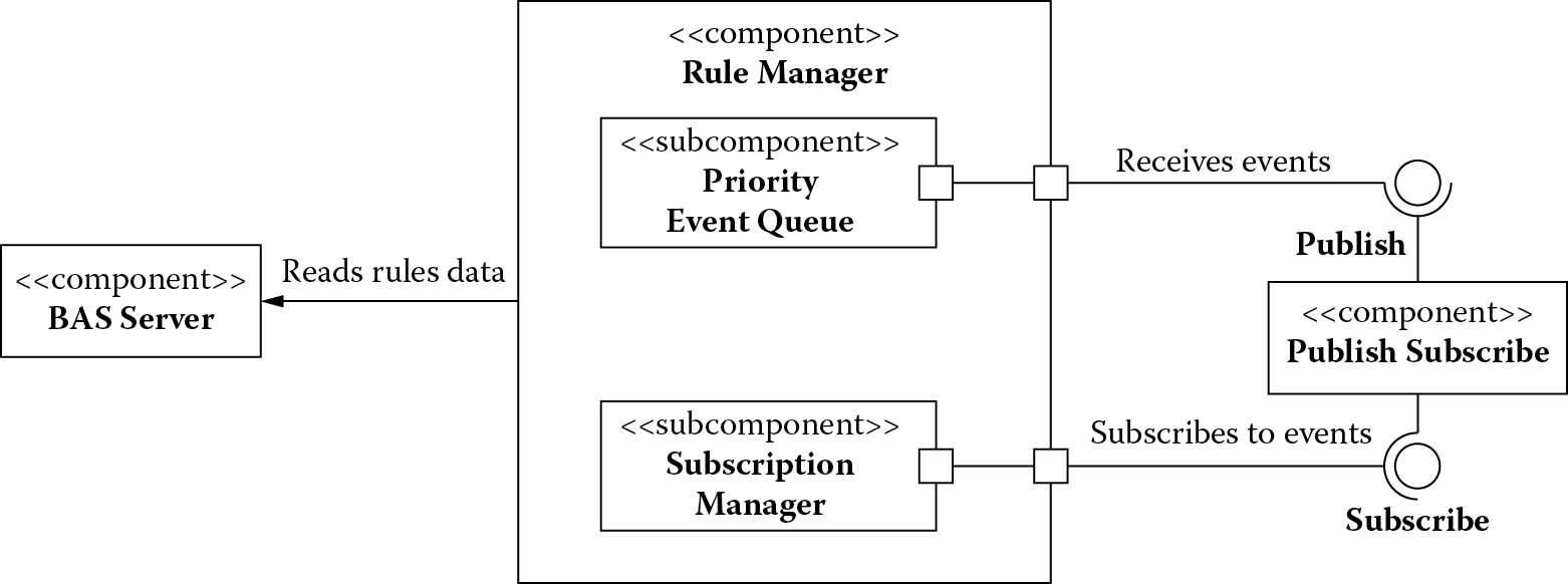
For the rule manager to process multiple concurrent events, our primary performance design concern is how best to manage the resources. For this, we use a schedule resources tactic and decompose the rule manager into a subscription manager that subscribes to events received by the publish-subscribe connector and a priority event queue that receives these subscribed events and queues them in a priority order. We show the results of this decomposition in Figure 7.4.
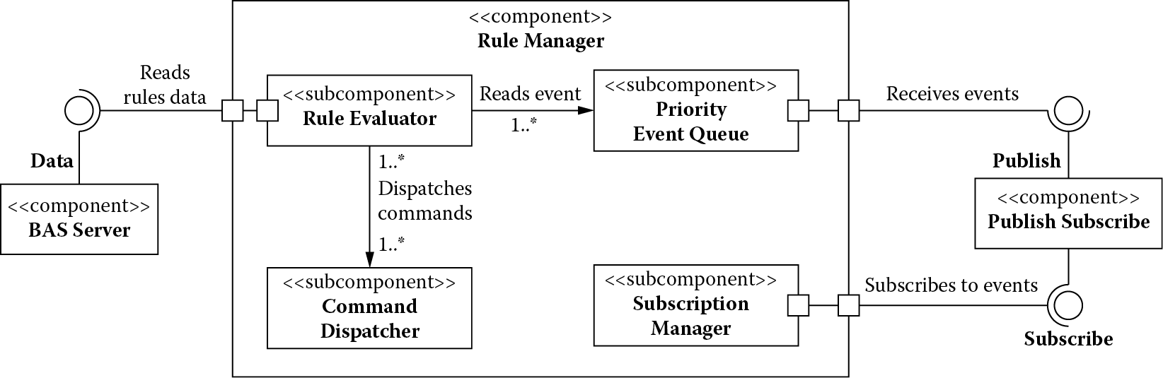
Next, we use the introduce concurrency tactic to process multiple events simultaneously. We further decompose the rule manager and introduce a subcomponent rule evaluator that reads events from the event queue and selects appropriate rules to evaluate in response to the given events. If the conditions for these rules are met, then it triggers the action, which may involve executing one or more commands. The command dispatcher subcomponent handles the dispatching of these commands. We show the results of this decomposition in Figure 7.5.
The rule manager maintains a pool of rule evaluators and command dispatchers so they can process rules and commands concurrently. Some of these benefits, however, are mostly visible when multiple computational nodes are available.
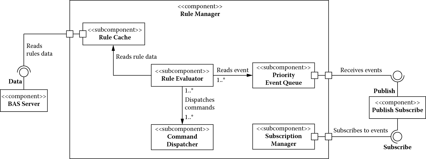
Finally, we notice that the rule evaluator reads the rules from the Building Automation System (BAS) server. We use the maintain multiple copies tactic and create a rule cache to further improve the performance. The rule manager is responsible for maintaining this cache. Figure 7.6 shows the addition of a cache.
We address the functional responsibilities next.
7.3.2 Addressing Functional Responsibilities
To handle evaluation and execution of automation rules, we need the capability to create and maintain these rules. To achieve this, we introduce a domain object rule and assign to it these responsibilities. Similarly, we introduce a domain object command that encapsulates all the information (such as the field device identifier, its properties and their values, etc.) required to execute a command. With these additions, Figure 7.7 shows the final architecture of the rule manager.
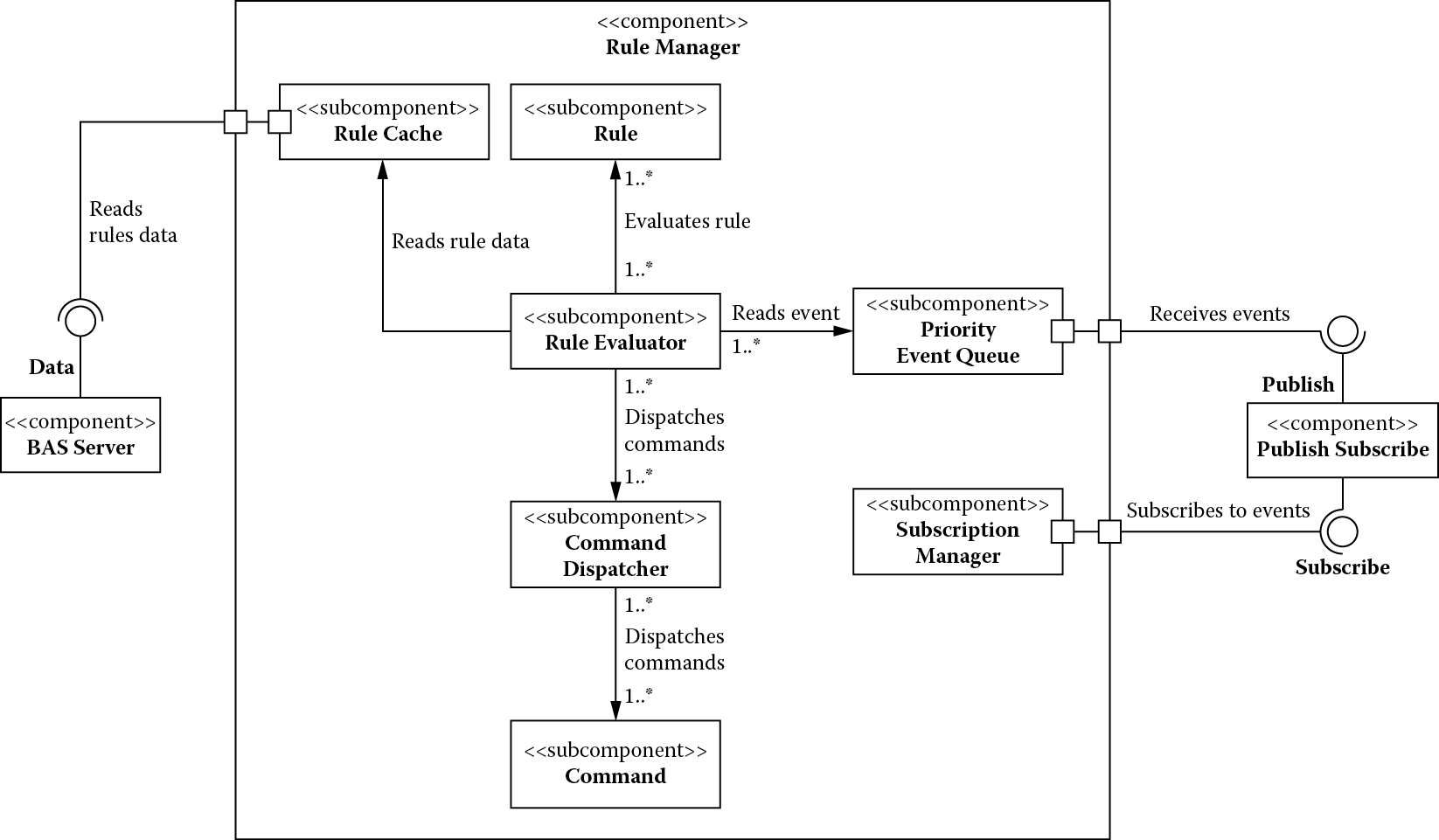
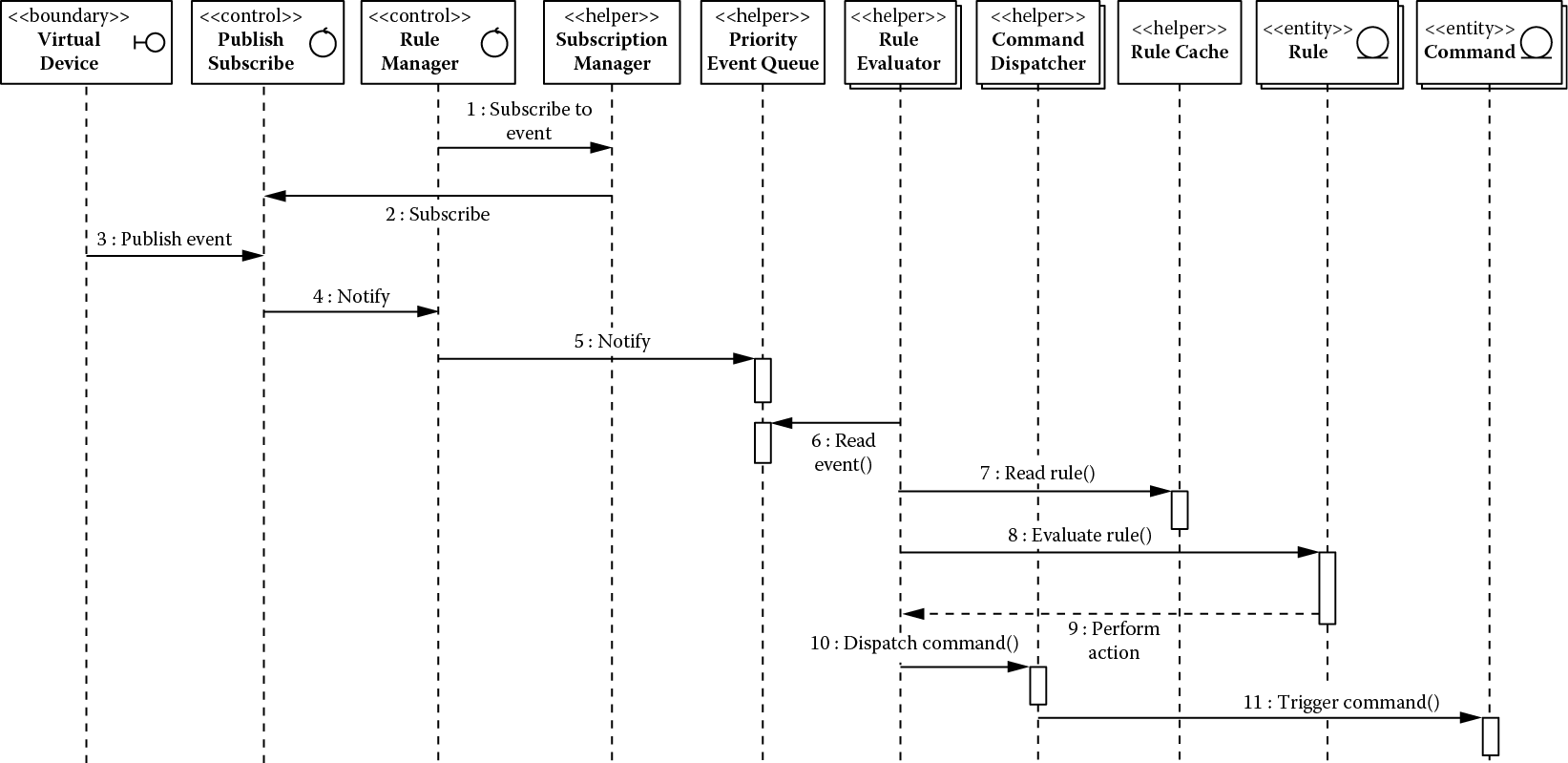
Figure 7.8 shows the interaction among the elements of the final architecture to handle an event generated by a field device. If we compare this figure with the conceptual diagram initially created in Figure 7.2, we see we have introduced several helper classes that address the performance design concerns related to the architecture responsibilities assigned to the rule manager.
7.4 Summary
The output at the end of architectural analysis and detailed design is a component architecture with its related design decisions traceable to the business goals and a substantial specification for system interfaces and domain and helper objects. System interfaces are a product of elaborating the use cases that describe the interaction of an actor at the boundary of a system and result in the creation of boundary and controller classes that manage this interaction. Domain objects are a product of the problem domain model that capture concepts from the problem domain of significant value. They result in creation of controller classes that manage the domain objects, entity classes that represent the domain objects, and the database schema used for persisting the domain objects. Helper classes result from addressing many of the architectural design concerns related to a component.
7.5 Question
- Using the techniques described in this chapter, create a detailed design for
- Alarm manager
- Presentation manager
- Publish-subscribe connector
References
L. Bass, P. Clements, and R. Kazman, Software Architecture in Practice, third edition. Boston: Addison-Wesley, 2013.
C. Larman, Applying UML and Patterns, third edition. Upper Saddle River, NJ: Prentice-Hall, 2005.