
Chapter 5
Creating the Architecture
5.1 Introduction
Chapter 4 discussed patterns and tactics that can be used for creating an architecture of a system. We can take the list of architectural drivers for a given system and, for each driver, consider patterns or tactics that might address design concerns inherent in that driver. When the first driver on the list is considered, it will yield a structure (based on patterns or tactics selected) that will satisfy its design concerns. We can then move to the next driver on the list and examine if the structure resulting from satisfying the first driver also satisfies the design concerns of this driver. If it does, we can move on to the next driver, but if it does not, we must examine how we refine this structure (using additional patterns or tactics) to satisfy these concerns. We continue to repeat this process until the structure has been sufficiently refined to yield a final architecture that addresses all design concerns associated with all the drivers on the list. It should be noted that design concerns are seldom completely addressed. Conflicting design concerns have to be traded against each other and reasonable compromise has to be reached. Hence, creating an architecture is about finding the middle ground by trading off competing and conflicting objectives.
The attribute-driven design (ADD) method (Bass et al., 2013; Woods, 2007), developed at the Software Engineering Institute (SEI), is one approach that follows a recursive refinement process similar to the one outlined. ADD requires as input (a) a prioritized set of architectural drivers and (b) the functional responsibilities of the system. In general, ADD starts with the highest-priority driver and picks the element of the system that is most relevant to address the design concerns of the driver. In a green field project, that element would be the system itself (at the beginning of such a project, the system is a black box that has not gone through any refinement) and is also assumed to be the one that fulfills all of the functional responsibilities given as input. This element is then refined or decomposed using appropriate patterns or tactics to satisfy the given architectural driver, and its functional responsibilities are reallocated among the child elements resulting from this decomposition. ADD then moves to the next high-priority architectural driver following the same refinement process all over again until all drivers have been considered and a final architecture reached that reflects a reasonable balance for all design concerns.
It should be noted that the act of decomposing elements to create new elements gives rise to additional responsibilities. These responsibilities would stem from the newly created elements addressing design concerns associated with the architectural driver they satisfy.
The following sections illustrate the application of the ADD method to the building automation system (Sangwan et al., 2008) introduced in the previous chapters.
5.2 Architecture of the Building Automation System
For ease of cross-referencing, the architectural drivers and functional responsibilities of the building automation system are reproduced from the previous chapters in Table 5.1 and Table 5.2. Recall that architectural drivers were derived from quality attribute scenarios and functional responsibilities and constraints with implied quality concerns (see Section 4.2). The functional responsibilities were derived from the system’s use cases (see Section 3.3).
Architectural Drivers and Functional Responsibilities of the Building Automation System
|
Architectural Driver |
||
|
No. |
Description |
Priority |
|
1 |
Support for adding new field device |
(H, H) |
|
2 |
International language support |
(H, M) |
|
3 |
Nonstandard unit support |
(H, M) |
|
4 |
Latency of alarm propagation |
(H, H) |
|
5 |
Load conditions |
(H, H) |
Note: H, high; M, medium.
Functional Responsibilities of the Building Automation System
|
Functional Responsibilities |
|
|
1 |
Send commands to a field device |
|
2 |
Receive events from a field device |
|
3 |
Perform semantic translation for device data |
|
4 |
Configure a field device |
|
5 |
Route data to a field device |
|
6 |
Evaluate and execute automation rules |
|
7 |
Send automation commands |
|
8 |
Generate alarm notifications |
|
9 |
Display device data |
|
10 |
Capture/relay user commands |
|
11 |
Display alarm notifications |
|
12 |
Edit/create automation rules |
|
13 |
Retrieve data from a field device |
|
14 |
Store field device configuration |
|
15 |
Propagate change-of-value notifications |
|
16 |
Authenticate and authorize users |
|
17 |
Persist rules, user preferences, alarms |
We start with a monolithic system as shown in Figure 5.1. We use standard Unified Modeling Language (UML) 2.0 notation and two views of the architecture. Figure 5.1 is a static module decomposition view that shows a decomposition hierarchy of modules (elements that represent coherent units of implementation) that make up the system. Figure 5.2 is a dynamic component and connector view that shows components (independently deployable and configurable elements) of the system and the connectors (communication links between components) that allow the components to interact with each other and exchange information. There may not necessarily be one-to-one mapping between modules and components; several modules may be deployed together as a component, or a module may be deployed across several components. When this is the case, a mapping between the two is provided in the narrative; otherwise, one-to-one mapping should be assumed.
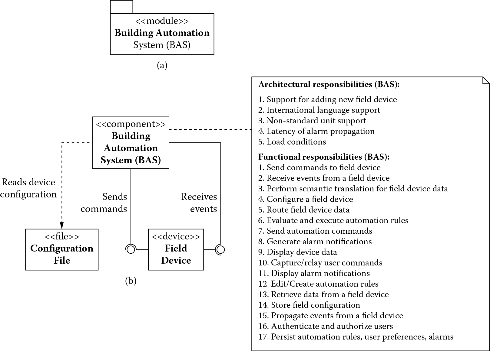
(a) Module decomposition view and (b) component-and-connector view of the monolithic building automation system.
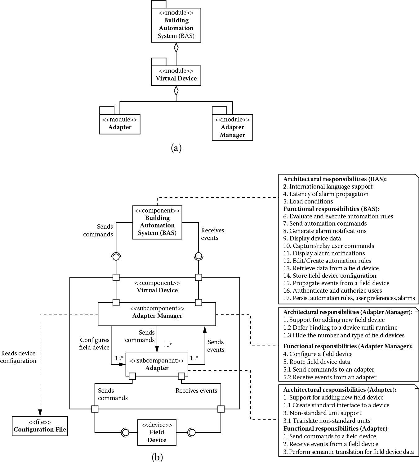
(a) Module decomposition view and (b) component-and-connector view showing building automation system after addressing support for adding new field devices.
Figure 5.1 shows BAS (Building Automation System) as the only module that makes up the building automation system, and Figure 5.1 shows BAS as the only component that interfaces with the field devices it manages and reads the initial configurations of the devices from a set of configuration files. The monolith, as the only system component, is responsible for all functionality (Table 5.2) to be implemented along with satisfying all the architectural drivers (Table 5.1). We show this allocation of responsibilities only in the component-and-connector view in Figure 5.1 (this choice is arbitrary, and the module decomposition view in Figure 5.1 could easily have been used). This convention is followed throughout this example.
Obviously, the monolithic structure cannot satisfy most of these architectural drivers, and we need to decompose it further until all of these drivers are satisfied. We begin with one of our highest-priority architectural drivers.
5.2.1 Support for Adding New Field Devices
Recall that this driver to provide support for adding new field devices is concerned with a field engineer being able to integrate a new field device into the building automation system while the system is operational. The system should continue to operate and experience no downtime or side effects. Having this dynamic reconfiguration and device management feature supports product variability so devices of varying capabilities from many different manufacturers can be integrated into the system.
As seen in previous discussions, these types of requirements relate to the modifiability quality attribute, the ease with which a new hardware device can be integrated into a system while it is in operation. To satisfy these requirements, we can apply the modifiability tactics to limit the impact of change and minimize the number of dependencies on the part of the system responsible for integrating new hardware devices. There are really three design concerns to be addressed:
- Limit the impact of a change: Our interest is to minimize the number of changes that need to be made when adding a new field device.
- Limit the ripple effect of a change: We would also like to minimize the number of dependencies on those elements that need to change as a result of adding a new field device; this would minimize the change from propagating to other parts of the system.
- Defer the binding time of a change: A new field device should be deployed when the system is in operation, and the field engineers or nonprogrammers should be able to manage such deployment.
We address these concerns by decomposing BAS into adapters for field devices, a tactic of anticipation of expected changes; this limits the impact of change to just the adapter. We use two additional architectural tactics to limit the ripple effect of change. First, we specify a standard interface to be exposed by all adapters (maintain existing interfaces). Second, we use the adapter as an intermediary responsible for semantic translation of all the data received from different field devices into a standard format. As a side effect, using the adapter as an intermediary for semantic translation of data also addresses architectural driver 3, which requires support for converting nonstandard units by different devices.
The adapters are assigned the following functional responsibilities:
- Send commands to the field device
- Receive events from field device
- Perform semantic translation for field device data
By virtue of addressing architectural drivers 1 and 3, adapters are assigned the following additional responsibilities:
- Create standard interface to a device
- Translate nonstandard units
Allocation of these responsibilities to the adapters leads to a realization that the BAS is still sensitive to a change in the number of field devices to which it is connected and must include logic to route commands and data to and from the correct adapter. To address this concern, we use the tactic of hiding information, introducing an adapter manager to hide information about the number and type of field devices actually connected. The adapter manager together with the adapters creates a virtual device; that is, for all other components of the building automation system, there is practically one field device to interact with at all times. The adapter manager internally maintains a routing table that associates logical identifiers with the field devices. The logical identifiers are associated with messages exchanged with BAS, and the adapter manager routes these messages to and from (adapters of) the correct field through the use of the routing table.
In addition, the adapter manager uses the following two architectural tactics to address deferring the binding time design concern:
- Runtime registration: This supports plug-and-play operation, allowing nonprogrammers to deploy new field devices.
- Configuration files: This tactic enables setting of configuration parameters, such as the type of a device and its initial property values, for bootstrapping a device at startup.
Essentially, when field engineers deploy a device, the adapter manager can read the configuration parameters from its configuration file, locate and deploy the correct adapter for the device, update the routing table, and start communicating with the device via its adapter.
The adapter manager is assigned the following functional responsibilities:
- Configure a field device
- Route data to a field device
By virtue of addressing architectural driver 1, the adapter manager is also assigned the following additional responsibilities:
- Defer binding to a field device until runtime
- Hide the number and type of field devices
The result of applying these tactics is shown in Figure 5.2.
Figure 5.2 shows how architectural driver 1 is satisfied partly by the adapter and partly by the adapter manager (by way of additional architectural responsibilities allocated to them), and together they implement what we refer to as a virtual device. BAS continues to act as a placeholder for the remaining architectural drivers and functional responsibilities that need to be addressed. Again, Figure 5.2 shows the static module decomposition and Figure 5.2 the dynamic component-and-connector view of the system, and we limit showing allocation of responsibilities to Figure 5.2.
At this stage, architecture driver 1 is satisfied (and as a side effect, so is architecture driver 3), and we can move on to the next driver or set of drivers in the priority order. For instance, in this iteration we only treated a single driver (architecture driver 1) to drive the decomposition of the system, but this need not be the case. Drivers that have similar needs can be addressed together. Therefore, in the next iteration, we treat architecture drivers 4 and 5 together because they have similar performance concerns.
5.2.2 Addressing Latency and Load Conditions
Recall that driver 4 is concerned with regulatory compliance whereby a life-critical alarm has to be reported within 3 s of the occurrence of the event that raised the alarm. Driver 4, on the other hand, is related to a constraint that requires the building automation system to handle a wide array of configurations, ranging from 500 to 500,000 field devices. This constraint alerts us to the fact that a large number of field devices could create a significant load on the system, which must be managed to avoid an undesirable impact on how quickly an alarm event can make it through the system.
All of these requirements relate to the performance quality attribute that targets the latency and throughput needs of a system to make it more responsive. To address the latency and throughput needs of drivers 4 and 5, we can apply performance tactics further decomposing BAS to manage the demand for the resources and manage the resources more effectively so they can more efficiently meet this demand. Therefore, there are two design concerns to be addressed:
- Manage demand for a resource: The arrival of change-of-property-value events from the various field devices (for example, a thermostat reporting a change in its temperature property value) and the evaluation of automation rules in response to these events (for example, if the temperature reported by the thermostat is too high, then check the status of the fire alarms and smoke detectors) are sources of resource demands and must be managed.
- Manage a resource: The demand on resources may also have to be managed to reduce the latency of life-critical events and alarm propagation.
To address these concerns, we move the responsibility of rule evaluation and execution, and alarm generation, respectively, from BAS to a separate rule manager component and an alarm manager component. By virtue of being separate, these components can now be easily moved to dedicated execution nodes if necessary. In doing so, we are making use of the increase available resources tactic to address the resource management concern (alarm-handling capability obtains its own resources for efficient handling of life-critical events) and the reduce computational overhead tactic to address the resource demand concern (we can colocate all alarm-handling elements on their own dedicated node and reduce the latency of interelement communication).
We use an additional tactic to address the resource management concern. This tactic relies on introducing concurrency to reduce delays in processing time. Concurrency is used inside the rule manager and the alarm manager components to perform simultaneous rule evaluations. The results of applying these tactics are shown in Figure 5.3.
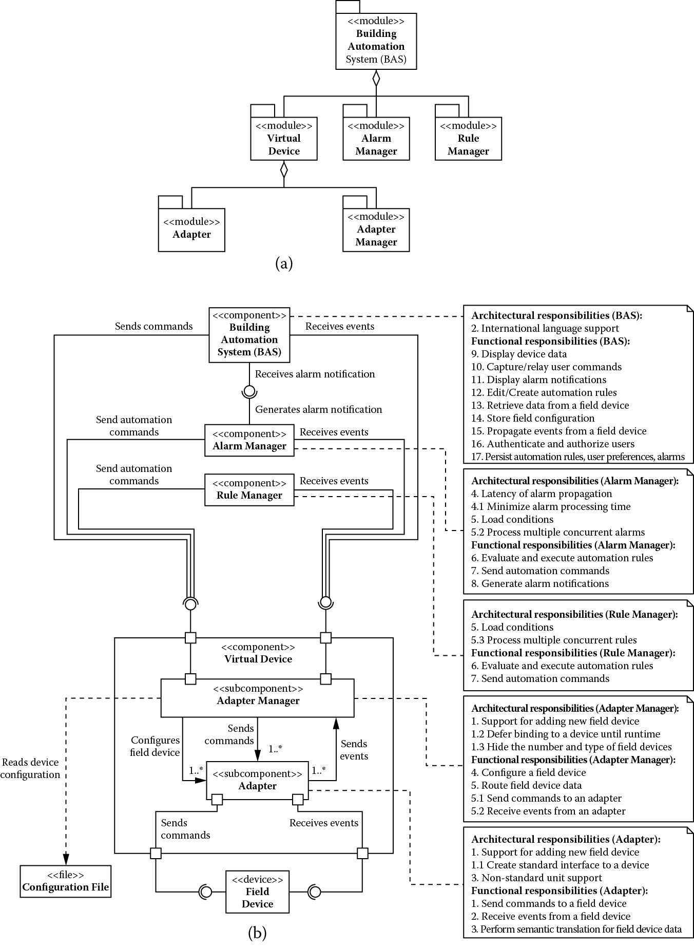
(a) Module decomposition view and (b) component-and-connector view showing building automation system after addressing support for performance architectural drivers.
As usual, we limit showing allocation of responsibilities to Figure 5.3, and BAS acts as a placeholder for the remaining architectural drivers and functional responsibilities that need to be addressed. The following functional responsibilities have been assigned to the rule manager and alarm manager components:
- Evaluate and execute automation rules
- Send automation commands
By virtue of addressing driver 5, they both also obtain an additional architectural responsibility:
- Process multiple concurrent rules
In addition, we assign the following functional responsibility to the alarm manager:
- Generate alarm notifications
Because it also handles driver 4, we assign the following architectural responsibility to the alarm manager:
- Minimize alarm-processing time
At this stage, architecture drivers 1, 3, 4, and 5 are satisfied, and only driver 2 remains. We address this driver in the next iteration.
5.2.3 Addressing International Language Support
Recall that driver 2 is concerned with a developer being able to package a version of the building automation system with new language support in 80 person-hours, giving users of the system the ability to personalize the user interface to a language and locale of their choice. These internationalization requirements relate to the modifiability quality attribute, the ease with which a system can be configured to support a new language and locale. To satisfy these requirements, we can apply the modifiability tactics to limit the impact of change and minimize the number of dependencies on the part of the system responsible for handling internationalization. There are two design concerns to be addressed:
- Localize changes: This relates to minimizing the number of changes to be made to configure the building automation system for a new language and locale.
- Prevention of ripple effects: This relates to minimizing the number of modules affected as a result of changes that result from configuring the building automation system for a new language and locale.
We address these concerns by further decomposing BAS into a separate presentation module and using the following modifiability tactics:
- Anticipation of expected changes: Changes related to language and locale are localized to a single presentation module.
- Intermediary: The presentation module also acts as an intermediary, preventing ripple effects of changes related to language and locale from propagating to the rest of the system.
We could have treated the building automation system as a collection of independently cooperating elements and chosen to associate a presentation manager with every module in the system, such as the alarm manager, rule manager, and virtual device. This would give us great flexibility in tailoring the user interface to the specific and unique human-computer interaction needs of a given module. However, the internationalization issues must be dealt with in multiple different modules. There is a trade-off between flexibility and modifiability. Because we do not need the added flexibility, we stick with the design decisions we have made. The results of applying these tactics are shown in Figure 5.4.
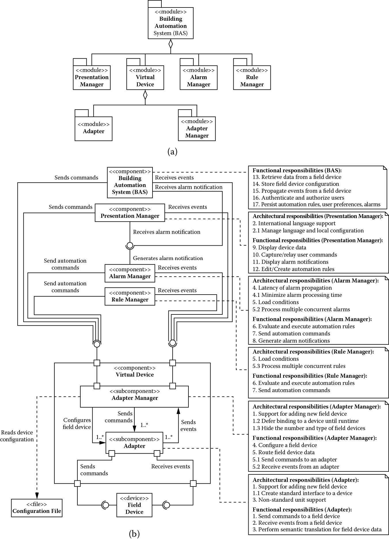
(a) Module decomposition view and (b) component-and-connector view showing building automation system after addressing support for international languages.
We assign the following responsibilities to the presentation module:
- Display device data
- Capture/relay user commands
- Display alarm conditions
- Edit/create automation rules
By virtue of addressing architectural driver 2, the presentation module receives the following additional architectural responsibility:
- Manage language and locale configuration
5.3 Architecture Trade-Offs
As previously mentioned, the architecture elaboration process we are using is iterative. Moreover, the tactics we choose to implement can often have a negative impact on the quality attributes they do not target specifically. In the case of the building automation system, we focused on modifiability and performance tactics, which can have a negative impact on each other. We revisit the modifiability and performance drivers next to address these issues.
5.3.1 Revisiting Modifiability Drivers
Introducing performance tactics resulted in creation of multiple components (rule manager and alarm manager, for instance) that now depend on the virtual device. Therefore, based on its current structure, we can predict that some changes to the virtual device have the potential to propagate to several other components of the building automation system. We would like to minimize the ripple effect of these changes. To achieve this objective, we introduce a publish-subscribe bus as shown in Figure 5.5.
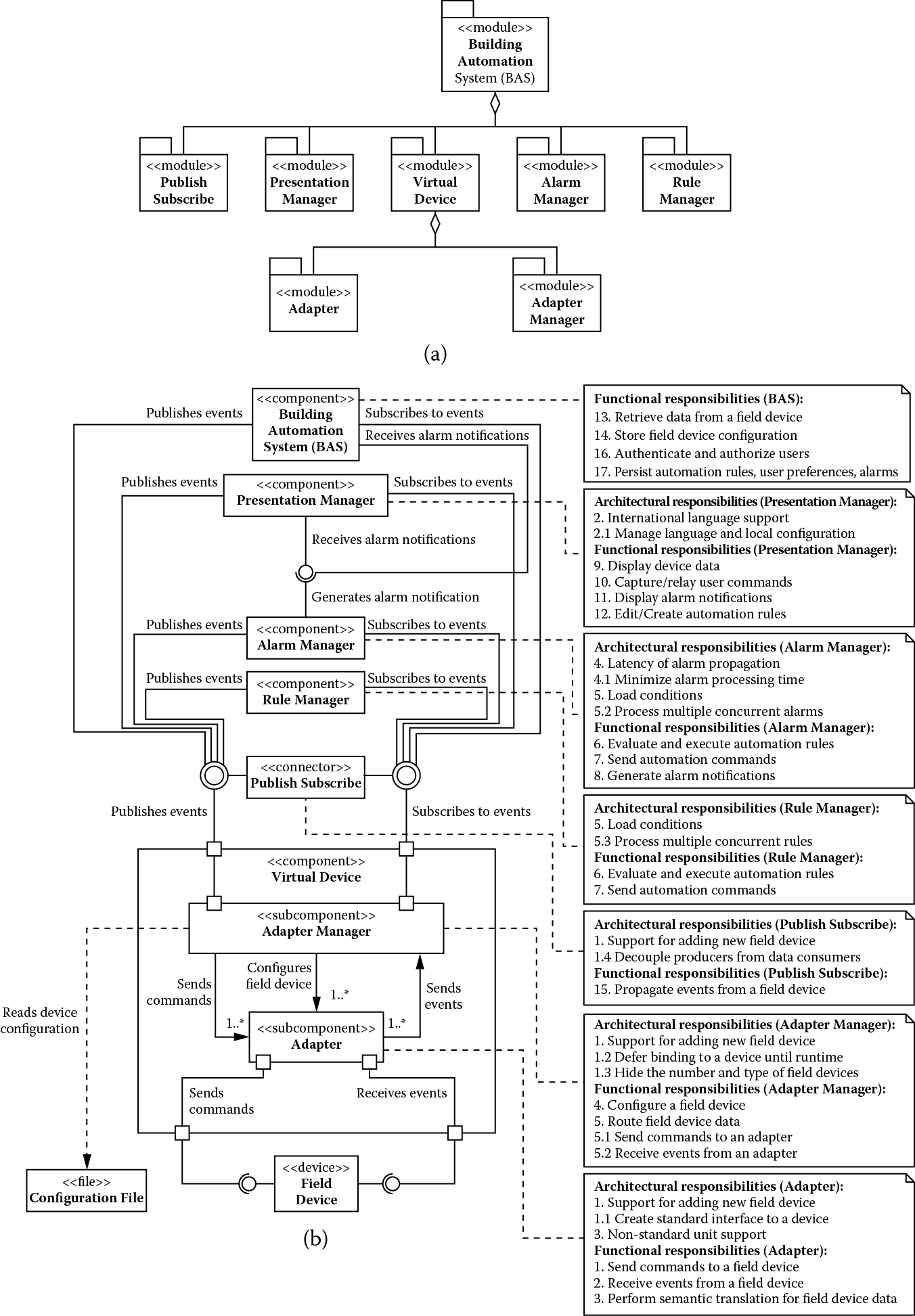
(a) Module decomposition view and (b) component-and-connector view showing building automation system after addressing the modifiability and performance trade-off.
The publish-subscribe bus uses three modifiability tactics. First, it alleviates the syntactic dependencies of intercomponent calls by acting as a standard interface intermediary. Second, using the module generalization tactic makes it invariant to the type of events it transports. This generalization allows new types of events to be transported with no modification to the publish-subscribe component. Finally, it relies on runtime registration to allow system extensibility by adding publishers and subscribers.
We allocate the following responsibility to the publish-subscribe bus:
- Propagate change-of-value notifications
By virtue of decoupling the rest of the system from the virtual device, we also assign to it the following additional architectural responsibility:
- Decouple data consumers from data producers
5.3.2 Revisiting Performance Drivers
By examining the current system structure, it can be seen that every time the rule manager, the alarm manager, or the presentation manager needs to query a field device, it needs to make a call that traverses multiple components along the way to the field device. Because crossing component boundaries typically introduces computational overhead, and because the querying latency of field devices is a constraint over which we have no control, we decompose the virtual device and introduce a cache component to improve device-querying performance. This is shown in Figure 5.6.
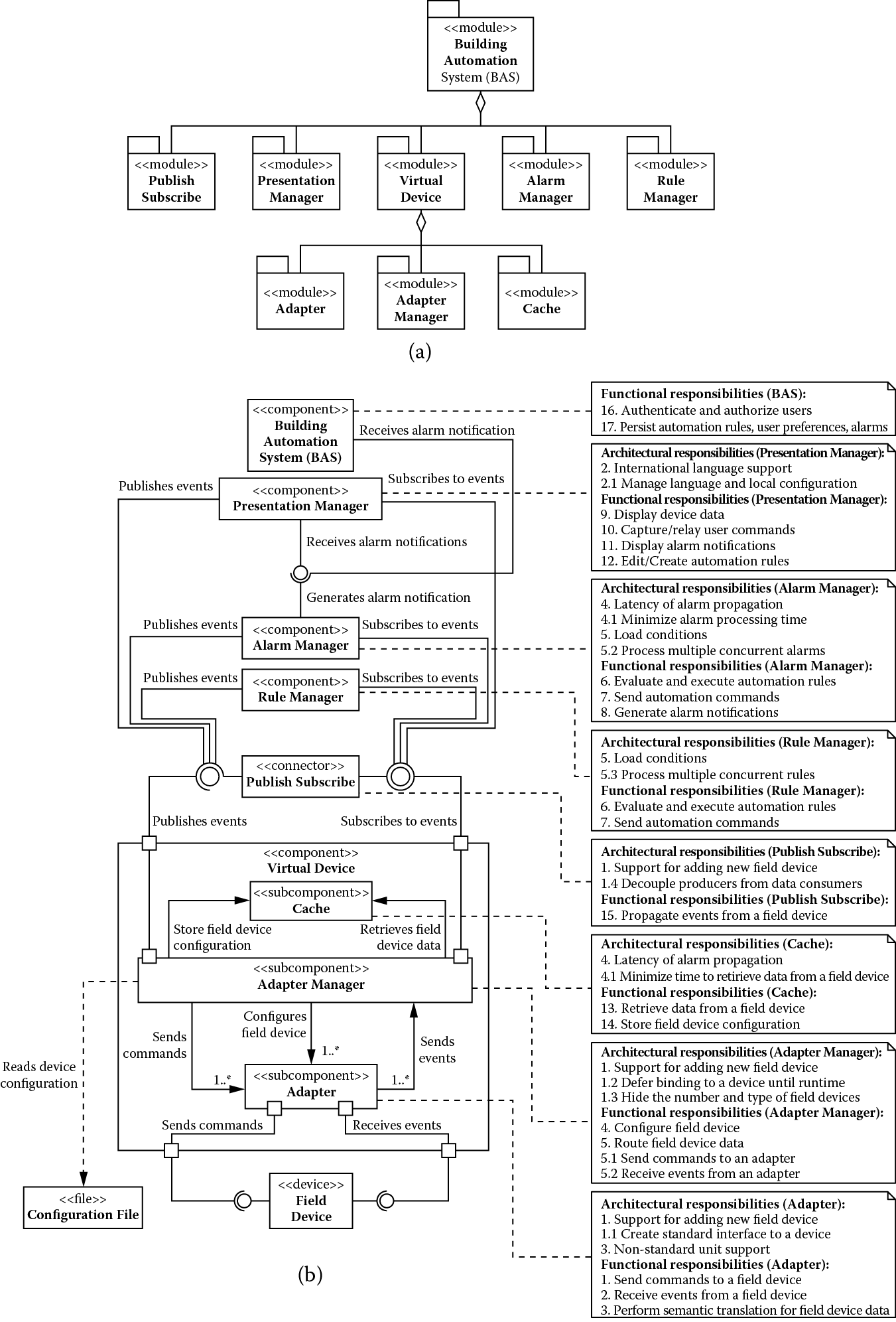
(a) Module decomposition view and (b) component-and-connector view showing building automation system after addressing the performance and modifiability trade-off.
This cache provides field device property values to the system, saving part of the performance cost incurred when querying the actual field devices. The performance gains are seen because we reduce the number of component and machine boundaries traversed for each query. A cache is really the application of the performance tactic of the maintaining multiple copies of data. We allocate the following functional responsibilities to the cache:
- Retrieve data from a field device
- Store field device configuration
In addition, we assign the following architectural responsibility related to improving performance:
- Minimize time to retrieve data from a field device
There is never a perfect architecture that optimally satisfies all of its requirements. All architectural designs involve trade-offs.
5.4 The Final Architecture
At this stage, all architectural drivers have been addressed, but BAS, which has been acting as a placeholder for unaddressed requirements, still has two functional requirements related to managing authentication/authorization of users of the system and the persistence of rules, alarms, and user preferences. We introduce a new component, BAS server, assigning it these remaining responsibilities. The final architecture is shown in Figure 5.7.
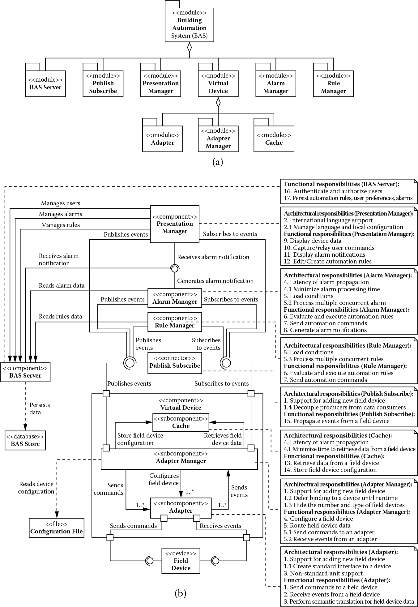
(a) Module decomposition view and (b) component-and-connector view showing building automation system after addressing all remaining requirements.
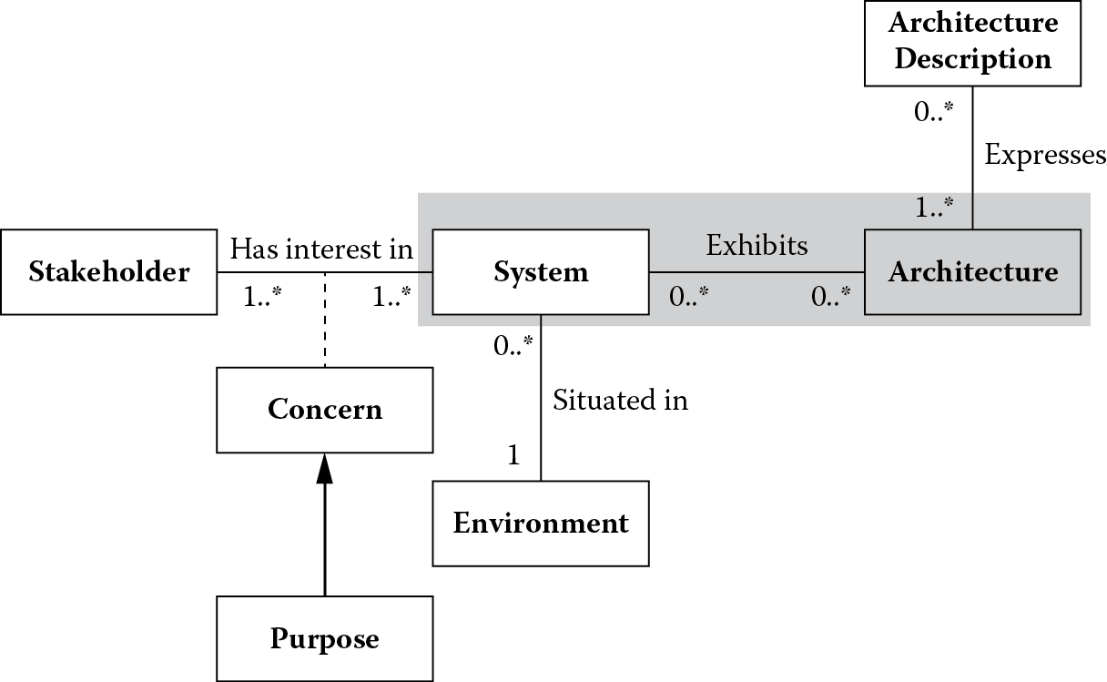
5.5 Summary
This chapter explored the shaded portion of International Organization for Standardization/International Electrotechnical Commission (ISO/IEC) 42010 conceptual framework for system and software architecture shown in Figure 5.8.
We demonstrated the use of ADD, a recursive decomposition method for architecture design, by applying it to the building automation system. We used numerous patterns and tactics that were discussed in the previous chapter to address design concerns inherent in the architectural requirements that drove the design of this system. In the process, we saw how architectural drivers conflict with each other and create trade-off situations that need to be resolved. In the end, the final architecture is not one that was perfect but one that tries to achieve a balance among competing design forces, some of which may conflict with each other.
5.6 Questions
- Refine the architecture presented in Figure 5.7 to improve the availability of the alarm component. Appropriately allocate functional responsibilities and architectural drivers to the elements of the resulting architecture.
- Tactics and patterns are important design decisions an architect makes to satisfy quality attribute requirements of a system. When analyzing a design or architecture of a system, the presence of these design decisions gives some measure of confidence that a certain quality attribute requirement will be satisfied. Justify your choices of the patterns or tactics for improving the availability of the alarm component in problem 1.
- Suppose a virtual field device needs to be highly available, with the stakeholder-provided availability scenario described in the following table:
Stimulus
A virtual field device hardware or software component fails.
Stimulus source
A fault occurs in a virtual field device hardware or software component.
Environment
At the time of failure, a virtual field device may be servicing a number of requests concurrently with other queued requests.
Artifact
Virtual field device.
Response
All query requests made before and during failure must be honored.
Response measure
The processing of requests must resume within a second.
- A few of the design concerns related to this scenario are shown in the following table:
Design Concerns
Subordinate Concerns
Description
Design Concerns
Subordinate Concerns
Description
Fault detection
Health monitoring
Detect fault and notify an element to deal with the fault
Fault preparation
Restart
Restart a component when failure occurs
Data integrity
Ensure that when a failure occurs there is sufficient state information on the failed component for recovery to occur
Fault recovery
Transparency to clients
Fault must be transparent to the clients
- List alternative patterns/tactics that can be used to address these concerns.
- Select patterns from the list and provide reasoning behind your choice.
- Capture your solution in an architecture view.
- Allocate responsibilities to the different elements in your architecture.
- Create a timing model to support your solution.
- A patient-monitoring system is a real-time embedded system used in hospitals to monitor a patient’s vital signs. It is a stand-alone bedside unit that obtains a patient’s data via pods attached to the patient or to other wide range of monitoring devices and communicates via a network to a central station. When the patient is being transported, the base unit can be detached from its docking station, and it travels with the patient. The base unit has a display that shows a patient’s physiological data as waveforms, parameter values, and alarms. For example, heart rate and pressures are discrete intermittent parameter values, whereas an electrocardiographic (EKG) recording of heart activity or arterial pressure is a continuous waveform sample. Hospital personnel select the kind of data to be displayed and display format. They can configure the alarms to go off when values fall outside the range they specify. The system can also display as much as 24 h of trend data. The product supports hundreds of customized user settings and thousands of application policy rules. These policy rules apply to features like EKG processing, parameter processing, alarms processing, patient admission, patient setup, display of patient information, two-channel local recording, network support, and acquisition and display of waveform and parameter information from other devices, such as ventilators and anesthesia systems. Some significant business goals for the patient-monitoring system, their associated engineering objectives, quality attributes, and quality attribute scenarios along with the priorities are given in the following table below; using this information as input, create an architecture of the patient-monitoring system using the attribute-driven design method:
References
L. Bass, P. Clements, and R. Kazman, Software Architecture in Practice, third edition. Boston: Addison-Wesley, 2013.
R. Sangwan, C. Neill, M. Bass, and Z. El Houda, Integrating a software architecture-centric method into object-oriented analysis and design. J. Syst. Softw. 81, 727–746, 2008.
W. Woods, A Practical Example of Applying Attribute-Driven Design (ADD), version 2.0 (CMU/SEI-2007-TR-005). Pittsburgh, PA: Carnegie Mellon Software Engineering Institute.